EP4495501A1 - Multi-circuit heat pump - Google Patents
Multi-circuit heat pump Download PDFInfo
- Publication number
- EP4495501A1 EP4495501A1 EP24182880.5A EP24182880A EP4495501A1 EP 4495501 A1 EP4495501 A1 EP 4495501A1 EP 24182880 A EP24182880 A EP 24182880A EP 4495501 A1 EP4495501 A1 EP 4495501A1
- Authority
- EP
- European Patent Office
- Prior art keywords
- heat pump
- condensers
- condenser
- evaporator
- working
- Prior art date
- Legal status (The legal status is an assumption and is not a legal conclusion. Google has not performed a legal analysis and makes no representation as to the accuracy of the status listed.)
- Pending
Links
Images


Classifications
-
- F—MECHANICAL ENGINEERING; LIGHTING; HEATING; WEAPONS; BLASTING
- F25—REFRIGERATION OR COOLING; COMBINED HEATING AND REFRIGERATION SYSTEMS; HEAT PUMP SYSTEMS; MANUFACTURE OR STORAGE OF ICE; LIQUEFACTION SOLIDIFICATION OF GASES
- F25B—REFRIGERATION MACHINES, PLANTS OR SYSTEMS; COMBINED HEATING AND REFRIGERATION SYSTEMS; HEAT PUMP SYSTEMS
- F25B6/00—Compression machines, plants or systems, with several condenser circuits
- F25B6/04—Compression machines, plants or systems, with several condenser circuits arranged in series
-
- F—MECHANICAL ENGINEERING; LIGHTING; HEATING; WEAPONS; BLASTING
- F25—REFRIGERATION OR COOLING; COMBINED HEATING AND REFRIGERATION SYSTEMS; HEAT PUMP SYSTEMS; MANUFACTURE OR STORAGE OF ICE; LIQUEFACTION SOLIDIFICATION OF GASES
- F25B—REFRIGERATION MACHINES, PLANTS OR SYSTEMS; COMBINED HEATING AND REFRIGERATION SYSTEMS; HEAT PUMP SYSTEMS
- F25B30/00—Heat pumps
- F25B30/02—Heat pumps of the compression type
-
- F—MECHANICAL ENGINEERING; LIGHTING; HEATING; WEAPONS; BLASTING
- F25—REFRIGERATION OR COOLING; COMBINED HEATING AND REFRIGERATION SYSTEMS; HEAT PUMP SYSTEMS; MANUFACTURE OR STORAGE OF ICE; LIQUEFACTION SOLIDIFICATION OF GASES
- F25B—REFRIGERATION MACHINES, PLANTS OR SYSTEMS; COMBINED HEATING AND REFRIGERATION SYSTEMS; HEAT PUMP SYSTEMS
- F25B1/00—Compression machines, plants or systems with non-reversible cycle
- F25B1/10—Compression machines, plants or systems with non-reversible cycle with multi-stage compression
-
- F—MECHANICAL ENGINEERING; LIGHTING; HEATING; WEAPONS; BLASTING
- F25—REFRIGERATION OR COOLING; COMBINED HEATING AND REFRIGERATION SYSTEMS; HEAT PUMP SYSTEMS; MANUFACTURE OR STORAGE OF ICE; LIQUEFACTION SOLIDIFICATION OF GASES
- F25B—REFRIGERATION MACHINES, PLANTS OR SYSTEMS; COMBINED HEATING AND REFRIGERATION SYSTEMS; HEAT PUMP SYSTEMS
- F25B41/00—Fluid-circulation arrangements
- F25B41/40—Fluid line arrangements
- F25B41/42—Arrangements for diverging or converging flows, e.g. branch lines or junctions
-
- F—MECHANICAL ENGINEERING; LIGHTING; HEATING; WEAPONS; BLASTING
- F25—REFRIGERATION OR COOLING; COMBINED HEATING AND REFRIGERATION SYSTEMS; HEAT PUMP SYSTEMS; MANUFACTURE OR STORAGE OF ICE; LIQUEFACTION SOLIDIFICATION OF GASES
- F25B—REFRIGERATION MACHINES, PLANTS OR SYSTEMS; COMBINED HEATING AND REFRIGERATION SYSTEMS; HEAT PUMP SYSTEMS
- F25B49/00—Arrangement or mounting of control or safety devices
- F25B49/02—Arrangement or mounting of control or safety devices for compression type machines, plants or systems
-
- F—MECHANICAL ENGINEERING; LIGHTING; HEATING; WEAPONS; BLASTING
- F25—REFRIGERATION OR COOLING; COMBINED HEATING AND REFRIGERATION SYSTEMS; HEAT PUMP SYSTEMS; MANUFACTURE OR STORAGE OF ICE; LIQUEFACTION SOLIDIFICATION OF GASES
- F25B—REFRIGERATION MACHINES, PLANTS OR SYSTEMS; COMBINED HEATING AND REFRIGERATION SYSTEMS; HEAT PUMP SYSTEMS
- F25B6/00—Compression machines, plants or systems, with several condenser circuits
- F25B6/02—Compression machines, plants or systems, with several condenser circuits arranged in parallel
-
- F—MECHANICAL ENGINEERING; LIGHTING; HEATING; WEAPONS; BLASTING
- F25—REFRIGERATION OR COOLING; COMBINED HEATING AND REFRIGERATION SYSTEMS; HEAT PUMP SYSTEMS; MANUFACTURE OR STORAGE OF ICE; LIQUEFACTION SOLIDIFICATION OF GASES
- F25B—REFRIGERATION MACHINES, PLANTS OR SYSTEMS; COMBINED HEATING AND REFRIGERATION SYSTEMS; HEAT PUMP SYSTEMS
- F25B2400/00—Component parts or details not otherwise provided for in this subclass
- F25B2400/07—Details of compressors or related parts
- F25B2400/075—Details of compressors or related parts with parallel compressors
-
- F—MECHANICAL ENGINEERING; LIGHTING; HEATING; WEAPONS; BLASTING
- F25—REFRIGERATION OR COOLING; COMBINED HEATING AND REFRIGERATION SYSTEMS; HEAT PUMP SYSTEMS; MANUFACTURE OR STORAGE OF ICE; LIQUEFACTION SOLIDIFICATION OF GASES
- F25B—REFRIGERATION MACHINES, PLANTS OR SYSTEMS; COMBINED HEATING AND REFRIGERATION SYSTEMS; HEAT PUMP SYSTEMS
- F25B2400/00—Component parts or details not otherwise provided for in this subclass
- F25B2400/13—Economisers
-
- F—MECHANICAL ENGINEERING; LIGHTING; HEATING; WEAPONS; BLASTING
- F25—REFRIGERATION OR COOLING; COMBINED HEATING AND REFRIGERATION SYSTEMS; HEAT PUMP SYSTEMS; MANUFACTURE OR STORAGE OF ICE; LIQUEFACTION SOLIDIFICATION OF GASES
- F25B—REFRIGERATION MACHINES, PLANTS OR SYSTEMS; COMBINED HEATING AND REFRIGERATION SYSTEMS; HEAT PUMP SYSTEMS
- F25B2700/00—Sensing or detecting of parameters; Sensors therefor
- F25B2700/13—Mass flow of refrigerants
- F25B2700/133—Mass flow of refrigerants through the condenser
-
- F—MECHANICAL ENGINEERING; LIGHTING; HEATING; WEAPONS; BLASTING
- F25—REFRIGERATION OR COOLING; COMBINED HEATING AND REFRIGERATION SYSTEMS; HEAT PUMP SYSTEMS; MANUFACTURE OR STORAGE OF ICE; LIQUEFACTION SOLIDIFICATION OF GASES
- F25B—REFRIGERATION MACHINES, PLANTS OR SYSTEMS; COMBINED HEATING AND REFRIGERATION SYSTEMS; HEAT PUMP SYSTEMS
- F25B2700/00—Sensing or detecting of parameters; Sensors therefor
- F25B2700/13—Mass flow of refrigerants
- F25B2700/135—Mass flow of refrigerants through the evaporator
Definitions
- This invention relates to the field of heat pumps, and more particularly, embodiments of the invention provide a simple, improved, and efficient multi-circuit heat pump.
- Heat pumps generally consist of a single unit having a single evaporator and a single condenser fluidically connected by a compressor, or multiple units including the single units (single evaporator, condenser, and compressor) in a series counterflow arrangement.
- the single unit with a single evaporator and condenser may have a low coefficient of performance (COP).
- COP coefficient of performance
- the temperature lift in the high-temperature heat pumps may result in a high-pressure ratio between the evaporator and the condenser and a low COP.
- the series counterflow arrangement may require multiple units, which may increase the cost.
- a multi-circuit heat pump comprising an evaporator, a plurality of condensers fluidically connected in series, and a plurality of compressor units configured between the evaporator and the plurality of condensers, such that one of the compressor units is fluidically configured between the evaporator and one of the condensers. That is, each compressor unit is fluidically configured between the evaporator and a respective condenser.
- each of the compressor units comprises a compressor operatively coupled to a motor, wherein each of the motors is configured to be independently operated at a predefined speed.
- the heat pump comprises a plurality of economizers, wherein one of the economizers is fluidically configured between the evaporator, one of the condensers, and the respective compressor. That is, each of the economizers is fluidically configured between the evaporator, a respective condenser, and a respective compressor.
- At least one of the plurality of condensers is a multi-pass heat exchanger.
- At least one of the plurality of condensers is a single-pass heat exchanger.
- each of the condensers comprises a conduit having a predefined number of turns and passes, disposed within a housing of the condenser and in thermal contact with a refrigerant coil associated with the corresponding condenser, wherein the conduit is configured for flow of a working-fluid therethrough.
- an outlet of the conduit associated with one of the condensers is fluidically connected to an inlet of the conduit associated with an adjacent condenser to connect the plurality of condensers in series.
- an outlet of the conduit associated with each of the condensers is adapted to facilitate tapping of the working-fluid from the respective condensers.
- the heat pump comprises a controller operatively coupled to one or more of the motors of the compressor unit, the evaporator, and the plurality of condensers, wherein the controller is configured to independently operate the motor of the compressor unit associated with each of the condensers based on temperature of the working-fluid to be maintained in and tapped from the conduit across each of the condensers.
- the working-fluid is water and the plurality of condensers comprises a water-cooled condenser.
- the working-fluid is air and the plurality of condensers comprises an air-cooled condenser.
- a multi-circuit heat pump comprising an evaporator, a condenser comprising a housing having a plurality of compartments isolated from each other and arranged in series within the housing, wherein each of the compartments comprises a refrigerant coil, and a plurality of compressor units configured between the evaporator and the plurality of compartments of the condenser, such that one of the compressor units is fluidically configured between the evaporator and one of the compartments. That is, each compressor unit is fluidically configured between the evaporator and a respective compartment.
- each of the compressor units comprises a compressor operatively coupled to a motor, wherein the motor of each compressor is configured to be independently operated at a predefined speed.
- the heat pump comprises a plurality of economizers, wherein one of the economizers is fluidically configured between the evaporator, one of the compartments, and the respective compressor. That is, each of the economizers is fluidically configured between the evaporator, a respective compartment, and a respective compressor.
- the condenser comprises a conduit having a predefined number of turns and passes disposed of within the housing and extending through each of the compartments, wherein the conduit is in thermal contact with the condenser coil of each of the compartments and configured to facilitate flow of a working-fluid therethrough.
- the conduit is adapted to facilitate tapping of the working-fluid from each of the compartments.
- the condenser comprises one or more partition walls disposed of within the housing to create and isolate the plurality of compartments, wherein the conduit extends through the one or more partition walls.
- the heat pump comprises a controller operatively coupled to one or more of the motors of the compressor unit, the evaporator, and the condenser, wherein the controller is configured to independently operate the motor of the compressor unit associated with each of the compartments based on temperature of the working-fluid to be maintained in and tapped from the conduit across each of the compartments.
- the working-fluid is water and the condenser is a water-cooled condenser.
- the working-fluid is air and the condenser is an air-cooled condenser.
- Heat pumps are generally employed for district heating, water heating, waste heat recovery, and the like in buildings, and for industrial applications.
- Existing heat pumps may have a single-unit arrangement including a single condenser fluidically connected to a single evaporator by a compressor.
- the heat pumps may be of a multiple-unit arrangement including a plurality of the single-units in a series counterflow arrangement, where each unit has a single evaporator fluidically connected to a single condenser by a compressor.
- the temperature lift in a high-temperature single-unit heat pump may be high, which may result in a high-pressure ratio between the evaporator and the condenser along with a low coefficient of performance (COP).
- COP coefficient of performance
- the series counterflow arrangement may require multiple units each having an evaporator, a condenser, and a compressor, which increases the overall cost, while also being bulky.
- the series counterflow arrangement may require multiple units each having an evaporator, a condenser, and a compressor, which increases the overall cost, while also being bulky.
- Embodiments of this invention provide a simple, improved, efficient, and cost-effective multi-circuit heat pump that has a lower pressure ratio between the evaporator and condenser and an improved coefficient of performance.
- the heat pump may include a single evaporator fluidically connected to multiple series connected condensers.
- the heat pump may involve smaller condensers compared to the condensers involved in the existing single-unit heat pump, which may further allow the use of smaller compressor motors compared to the existing single-unit heat pump for the same capacity.
- the condenser in the heat pump may be kept smaller than the condenser of the existing single unit, the stall behavior in the heat pump may be easier to manage.
- the evaporator is common for all the condensers in the heat pump, the architecture of the heat pump may have cost and space-saving advantages compared to the existing multiple-unit heat pump.
- the multi-circuit heat pump "heat pump” 100 may include a plurality of condensers 104-1 to 104-3 (collectively referred to as condensers 104, herein) that may be fluidically connected in series.
- the heat pump 100 may further include a single evaporator 102 that may be common for all condensers 104.
- the common evaporator 102 may be fluidically connected to each of the condensers 104 using a plurality of compressor units 106-1 to 106-3 (collectively referred to as compressor unit 106, herein) such that one of the compressor units 106 is fluidically configured between the evaporator 102 and one of the condensers 104, resulting in multiple circuits with a common evaporator 102. That is, each compressor unit 106 is fluidically configured between the evaporator 102 and a respective condenser 104.
- the compressor 106-1 may be associated with common evaporator 102 and the condenser 104-1 in the first circuit
- the compressor 106-2 may be associated with common evaporator 102 and the condenser 104-2 in the second circuit
- the compressor 106-3 may be associated with common evaporator 102 and the condenser 104-3 in the third circuit.
- the compressor unit 106 may include a compressor (also designated as 106, herein) fluidically connected between one of the condensers 104 and the evaporator 102 and a motor operatively coupled to the compressor 106.
- each of the motors may be configured to be operated independently at a predefined speed or rotation per minute (RPM) to independently control the operation of the compressors 106 based on the temperature and pressure of the refrigerant to be maintained in the multiple circuits or components of the heat pump 100.
- RPM rotation per minute
- Each of the condensers 104 may include a working-fluid conduit "conduit" (shown in dotted lines) having a predefined number of turns and/or passes, disposed within a housing of the condenser 104.
- the working-fluid conduit may be configured to allow flow of a working-fluid therethrough.
- the working-fluid may be water and the plurality of condensers 104 may include water-cooled condensers, which may be implemented to heat water and supply the heated or conditioned water to an area of interest (AOI).
- the working-fluid may be air and the plurality of condensers 104 may include air-cooled condensers, which may be implemented to heat air and supply the heated or conditioned air to an AOI.
- the working-fluid may be any fluid that may be conditioned by the heat pump.
- the working-fluid conduit of the condensers 104 may be in thermal contact with a refrigerant coil (condenser coil) (not shown) associated with the corresponding condenser 104 within the housing of the condenser 104. Further, the refrigerant coil of each condenser 104 may be fluidically connected to the coils (evaporator coil) of the common evaporator 102 via the compressor 106, the economizer, and a piping system in each circuit to enable the flow of the refrigerant between the evaporator 102 and the corresponding condensers 104, thereby enabling the exchange of heat therebetween and adjusting the temperature of the working-fluid at predefined temperatures in different condensers 104.
- a refrigerant coil condenser coil
- the heat pump 100 may include an economizer in each of the circuits.
- One economizer may be fluidically configured between the common evaporator 102, one of the condensers 104, and the respective compressor in each circuit, thereby forming the multi-circuit heat pump 100.
- the heat pump 100 may additionally include (not shown) a filter drier, an accumulator, a receiver, an expansion valve, and the like being configured in each circuit.
- An outlet of the conduit associated with the condensers 104 may be fluidically connected to an inlet of the conduit associated with an adjacent condenser 104 in the heat pump 100 to connect the plurality of condensers 104 in series.
- the outlet of the conduit associated with the condenser 104-1 may be fluidically connected to an inlet of the conduit associated with the adjacent condenser 104-2
- the outlet of the conduit associated with the condenser 104-2 may be fluidically connected to an inlet of the conduit associated with the adjacent condenser 104-3 in the heat pump 100 to connect the plurality of condensers 104-1 to 104-3 in series.
- At least one of the condensers 104 may be a multi-pass condenser or heat exchanger, where the working-fluid conduit has multiple passes. In other embodiments, at least one of the condensers 104 may be a single-pass condenser or heat exchanger where the working-fluid conduit has a single pass. For instance, as shown in FIG. 1B , the condensers 104-1 and 104-2 may be single-pass condensers, and the condenser 104-3 may be a two-pass condenser. Further, as shown in FIG. 1A , all the condensers 104-1 to 104-3 may be two-pass condensers.
- 'ECWT' may be the condenser water entering the first condenser 104-1
- ⁇ LCWT1' may be the condenser water leaving the first condenser 104-1
- 'LCWT2' may be the condenser water leaving the second condenser 104-2
- 'LCWT3' may be the condenser water leaving the third condenser 104-3.
- 'EEWT' may be the cool water (fluid) entering the evaporator 102
- 'LEWT' may be the heated water leaving the evaporator 102.
- the condensers 104-1 to 104-3 may be air-cooled condensers and air may be circulated through the condensers 104-1 to 104-3 to heat or condition the air.
- the outlet of the conduit associated with each of the condensers 104 may be adapted to facilitate tapping (not shown) of the working-fluid from the respective condensers 104.
- the taps connected to the conduit in each condenser 104-1 to 104-3 may allow users to tap out the working-fluid of the variable temperature range (T1-T4). For instance, as shown in FIGs.
- the temperature of the working fluid entering the first condenser 103-1 through the conduit may be T1 (say 60 °C), where the first condenser 104-1 may raise the temperature of the working-fluid to T2 (say 70 °C) and supply the heated working-fluid (say 70 °C) to the inlet of the second condenser 104-2. Further, the second condenser 104-2 may raise the temperature of the working-fluid from T2 (70 °C) to T3 (say 80 °C) and supply the heated working-fluid T3 (80 °C) to the inlet of the third condenser 104-3.
- the third condenser 104-3 may raise the temperature of the working-fluid from T3 (80 °C) to T4 (say 90 °C) and supply the heated working-fluid T4 (say 90 °C) through the outlet of the third condenser 104-3.
- the multi-circuit heat pump 100 allows users to tap out the heated working-fluid in a range of 60 °C to 90 °C. Accordingly, the number of condensers 104 in the heat pump 100 may be selected based on the temperature or temperature range of the working-fluid to be achieved using the heat pump 100.
- the heat pump 100 may include additional valves configured with the conduit to control the flow rate and volume of the working-fluid flowing through the conduit in different condensers 104 and further allow controlled tapping or outflow of working fluid from each condenser 104.
- the heat pump 100 may include temperature sensors 304-1 and flow meters/pressure sensors 304-2 to monitor the temperature and pressure of one or more of the working-fluid flowing through the condensers 104 and the refrigerant flowing through the evaporator 102, compressors 106, and condensers 104 of the heat pump 100.
- the plurality of condensers 104-1 to 104-3 associated with the heat pump 100 of FIGs. 1A and 1B may be installed as a single condenser unit at an area of interest (AOI) to heat the AOI to a predefined temperature or supply water heated in the predefined temperature range, and the like.
- AOI area of interest
- each of the condensers 104-1 to 104-3 associated with the heat pump 100 of FIGs. 1A and 1B may be installed at different locations in the AOI to heat the locations to different predefined temperatures or supply water heated in the predefined temperature range to the locations, but not limited to the like.
- the multi-circuit heat pump "heat pump" 200 including a single condenser 104 unit having multiple partitioned compartments 202 is disclosed.
- the heat pump 200 may be substantially similar to heat pump 100.
- the common components of heat pumps 100, 200 may be referred to using the same reference numerals.
- heat pump 200 includes a single condenser 104.
- the heat pump 200 may include a condenser 104 having a plurality of compartments 202-1 to 202-3 (collectively referred to as compartments 202, herein) that may be connected in series.
- the condenser 104 may include one or more partition walls 204-1 and 204-2 disposed within the housing of the condenser 104 to create and physically and thermally isolate the compartments 202-1 to 202-3 in a series arrangement.
- each compartment 202 may have a separate refrigerant coil disposed in the housing.
- a working fluid conduit (shown in dotted line) may extend through the partition walls and the housing of the condenser 104 to allow the flow of a working-fluid through the compartments 202-1 to 202-3 of the condenser 104.
- the heat pump 200 may further include a single evaporator 102 that may be common for all the compartments 202.
- the common evaporator 102 may be fluidically connected to refrigerant coils in each of the compartments 202-1 to 202-3 using a plurality of compressor units 106-1 to 106-2 such that one of the compressor units 106-1 to 106-3 (collectively referred to as compressor units 106, herein) is fluidically configured between the evaporator 102 and one of the compartments 202-1 to 202-3, resulting in multiple circuits with the common evaporator 102. That is, each compressor unit 106 is fluidically configured between the evaporator 102 and a respective compartment 202.
- the compressor unit 106 may include a compressor (also designated as 106, herein) fluidically connected between one of the compartments 202-1 to 202-3 and the evaporator 102 and motors 110-1 to 110-3 (collectively referred to as motors 110, herein) operatively coupled to the compressors 106-1 to 106-3, respectively. Accordingly, the refrigerant from the common evaporator 102 may be compressed and delivered to each compartment 202 by a separate compressor 106, resulting in multiple circuits with varying temperature lifts.
- a compressor also designated as 106, herein
- each of the motors 110 may be configured to be operated independently at a predefined speed or rotation per minute (RPM) to independently control the operation of the compressors 106-1 to 106-3 based on the temperature and pressure of the refrigerant to be maintained in the multiple circuits or components of the heat pump 200.
- RPM rotation per minute
- the working-fluid conduit of the condenser 104 may have a predefined number of turns and passes, disposed within the housing of the condenser 104 and extending through the compartments 202.
- the working-fluid may be water and the condenser 104 may be a water-cooled condenser, which may be implemented to heat the water and supply the heated or conditioned water to an area of interest (AOI).
- the working-fluid may be air and the condenser 104 may be an air-cooled condenser, which may be implemented to heat the incoming air and supply heated or conditioned air to an AOI. As illustrated in FIG.
- 'ECWT' may be the condenser water entering the first compartment 202-1
- 'LCWT1' may be the condenser water leaving the first compartment 202-1
- 'LCWT2' may be the condenser water leaving the second compartment 202-2
- 'LCWT3' may be the condenser 104 water leaving the third compartment 202-3.
- ⁇ EEWT' may be the cool water (fluid) entering the evaporator 102
- 'LEWT' may be the heated water leaving the evaporator 102.
- the condenser 104 may be an air-cooled condenser and air may be circulated through the compartments 202-1 to 202-3 to heat or condition the air.
- the heat pump 200 may include an economizer 108-1 to 108-3 (collectively referred to as economizers 108, herein) in each of the circuits.
- economizers 108 may be fluidically configured between the common evaporator 102, one of the compartments 202-1 to 202-3 of the condenser 104, and the respective compressor 106-1 to 106-3 in each circuit, thereby forming the multi-circuit heat pump 200.
- the heat pump 200 may additionally include (not shown) a filter drier, an accumulator, a receiver, an expansion valve, and the like being configured in each circuit.
- the working-fluid conduit of the condensers 104 may be in thermal contact with the refrigerant coil (condenser coil) (not shown) configured in the corresponding compartments 202 of the condenser 104. Further, the refrigerant coil of each compartment 202 may be fluidically connected to the coils (evaporator coil) (not shown) of the common evaporator 102 via the compressor 106, the economizer 108, and a piping system in each circuit to enable the flow of the refrigerant between the coils of the evaporator 102 and the corresponding compartments 202, thereby enabling the exchange of heat therebetween and adjusting the temperature of the working-fluid at predefined temperatures in different condensers 104.
- the refrigerant coil of each compartment 202 may be fluidically connected to the coils (evaporator coil) (not shown) of the common evaporator 102 via the compressor 106, the economizer 108, and a piping system in each circuit to enable the flow
- At least one of the compartments 202 of the condenser 104 may have the working-fluid conduit having multiple passes. In other embodiments, at least one of the compartments 202 of the condenser 104 may have the working-fluid conduit having a single pass.
- the heat pump 200 may include additional valves (not shown) configured with the conduit to control the flow rate and volume of the working-fluid flowing through the conduit in different compartments 202 and further allow controlled tapping or outflow of working fluid from each compartment. In addition, as shown in FIG.
- the heat pump 200 may include temperature sensors 304-1 and flow meters 304-2 to monitor the temperature and pressure of one or more of the working-fluid flowing through the compartments 202 and the refrigerant flowing through the evaporator 102, compressor 106, and compartments 202 of the heat pump 200.
- a section of the conduit in each compartment of the condensers 104 may be adapted to facilitate tapping (not shown) of the working-fluid from the respective compartment 202.
- the taps connected to the conduit in each compartment may allow users to tap out working-fluid of the variable temperature range.
- the temperature of the working fluid entering the first compartment 202-1 may be at T1 (say 60 °C), where the first compartment may raise the temperature of the working-fluid to T2 (say 70 °C) and supply the heated working-fluid T2 (70 °C) to the second compartment 202-2.
- the second compartment 202-2 may raise the temperature of the working-fluid from T2 (70 °C) to T3 (say 80 °C) and supply the heated working-fluid T3 (80 °C) to the third compartment 202-3.
- the third compartment 202-3 may raise the temperature of the working-fluid from T3 (80 °C) to T4 (say 90 °C) and supply the heated working-fluid (90 °C) through the outlet of the third compartment 202-3.
- the multi-circuit heat pump 200 allows users to tap out heated working-fluid in a range of T1 (60 °C) to T4 (90 °C).
- the number of compartments 202 in the condenser 104 may be selected based on the temperature or temperature range T1 to T4 of the working-fluid to be achieved using the heat pump 200.
- the heat pumps 100, 200 of FIGs. 1A and 2 may include a controller 302 operatively coupled to one or more of the motors 110 of the compressor units 106, the common evaporator 102, and the condenser(s) 104.
- the controller 302 may include a processor operatively coupled to a memory storing instructions executable by the processor to enable the controller 302 to perform one or more designated operations.
- the controller 302 may be in communication with the temperature sensors 304-1 and flow meters/pressure sensors 304-2 installed in the heat pump 100, 200 to receive the pressure and temperature data associated with the working-fluid and the refrigerant flowing in the heat pump 100, 200.
- the controller 302 may be in further communication with a thermostat 306 provided at the AOI where the heat pump 100, 200 is installed and/or with mobile devices of one or more users at the AOI.
- the controller 302 may receive, from the thermostat 306 or mobile devices of the users, a set of instructions pertaining to the temperature of air or temperature of working-fluid (water or air) to be provided or maintained at the AOI.
- the controller 302 may accordingly independently actuate the different compressors 106 and valves 112 associated with the heat pump to independently operate the compressors 106 at different or same RPM to compress refrigerant received from the evaporator 102 and further enable the supply of the compressed refrigerant to the condenser(s) 104 and supply of the refrigerant from the condenser(s) 104 back to the evaporator 102 or economizer 108, to heat the working-fluid at user-defined temperature or temperature range at the condenser end.
- the controller 302 is configured to independently operate the motors 110 of the compressor units 106 associated with each of the condensers 104 based on the temperature of the working-fluid to be maintained in and tapped from the conduit across each of the condensers, and/or based on temperature to be maintained across each of the condensers 104 or compartments 202, and/or based on a pressure ratio to be maintained between the evaporator 102 and each of the condensers 104.
- the number of condensers in the heat pump 100 of FIGs. 1A and 1B and/or the number of compartments 202 in the condenser of the heat pump 200 of FIG. 2 may be selected based on COP to be achieved and the temperature or temperature range of the working-fluid (water/air) to be maintained using the heat pump 100, 200.
- the improvement in COP achieved by the heat pump 100, 200 for the different number of condensers 104 in FIG. 2 or the different number of compartments 202 in the condenser 104 of FIG. 2 is shown in the Table below. TABLE No of compartments/ No. of condensers COP (%) 1 (Existing Single unit heat pump) 2.37 2 2.61 3 2.7 4 2.74 5 2.74 6 2.74
- the heat pump 100, 200 of FIGs. 1A and 2 provides a simple, improved, efficient, and cost-effective multi-circuit heat pump that has a lower pressure ratio between the evaporator and condenser and an improved coefficient of performance.
- the heat pump includes a single evaporator fluidically connected to multiple condensers or compartments that are connected in series, as a result, the heat pump involves smaller condensers compared to the condensers involved in the existing single-unit heat pump. This may further allow the use of smaller compressor motors compared to the existing single-unit heat pump for the same capacity.
- the condenser in the heat pump may be kept smaller than the condenser of the existing single unit, the stall behavior in the heat pump is also easier to manage.
- the evaporator is common for all the condensers in the heat pump, the architecture of the heat pump has cost and space-saving advantages compared to the existing multiple-unit heat pump.
- the remaining healthy condensers may operate with reduced load, while keeping the overall heat pump active.
Landscapes
- Engineering & Computer Science (AREA)
- Physics & Mathematics (AREA)
- Mechanical Engineering (AREA)
- Thermal Sciences (AREA)
- General Engineering & Computer Science (AREA)
- Heat-Pump Type And Storage Water Heaters (AREA)
Abstract
A multi-circuit heat pump (100) is disclosed. The heat pump comprises an evaporator (102), a plurality of condensers (104-1, 104-2, 104-3) fluidically connected in series, and a plurality of compressor units (106-1, 106-2, 106-3) configured between the evaporator and the plurality of condensers such that one of the compressor units is fluidically configured between the evaporator and one of the condensers.
Description
- This patent application claims the benefit of
US Provisional Patent Application No 63/508,967, filed on Jun 19, 2023 - This invention relates to the field of heat pumps, and more particularly, embodiments of the invention provide a simple, improved, and efficient multi-circuit heat pump.
- Heat pumps generally consist of a single unit having a single evaporator and a single condenser fluidically connected by a compressor, or multiple units including the single units (single evaporator, condenser, and compressor) in a series counterflow arrangement. For high-temperature heat pump applications, the single unit with a single evaporator and condenser may have a low coefficient of performance (COP). The temperature lift in the high-temperature heat pumps may result in a high-pressure ratio between the evaporator and the condenser and a low COP. Moreover, the series counterflow arrangement may require multiple units, which may increase the cost.
- According to a first aspect there is provided a multi-circuit heat pump. The heat pump comprises an evaporator, a plurality of condensers fluidically connected in series, and a plurality of compressor units configured between the evaporator and the plurality of condensers, such that one of the compressor units is fluidically configured between the evaporator and one of the condensers. That is, each compressor unit is fluidically configured between the evaporator and a respective condenser.
- Optionally, each of the compressor units comprises a compressor operatively coupled to a motor, wherein each of the motors is configured to be independently operated at a predefined speed.
- Optionally, the heat pump comprises a plurality of economizers, wherein one of the economizers is fluidically configured between the evaporator, one of the condensers, and the respective compressor. That is, each of the economizers is fluidically configured between the evaporator, a respective condenser, and a respective compressor.
- Optionally, at least one of the plurality of condensers is a multi-pass heat exchanger.
- Optionally, at least one of the plurality of condensers is a single-pass heat exchanger.
- Optionally, each of the condensers comprises a conduit having a predefined number of turns and passes, disposed within a housing of the condenser and in thermal contact with a refrigerant coil associated with the corresponding condenser, wherein the conduit is configured for flow of a working-fluid therethrough.
- Optionally, an outlet of the conduit associated with one of the condensers is fluidically connected to an inlet of the conduit associated with an adjacent condenser to connect the plurality of condensers in series.
- Optionally, an outlet of the conduit associated with each of the condensers is adapted to facilitate tapping of the working-fluid from the respective condensers.
- Optionally, the heat pump comprises a controller operatively coupled to one or more of the motors of the compressor unit, the evaporator, and the plurality of condensers, wherein the controller is configured to independently operate the motor of the compressor unit associated with each of the condensers based on temperature of the working-fluid to be maintained in and tapped from the conduit across each of the condensers.
- Optionally, the working-fluid is water and the plurality of condensers comprises a water-cooled condenser.
- Optionally, the working-fluid is air and the plurality of condensers comprises an air-cooled condenser.
- According to a second aspect there is provided a multi-circuit heat pump. The heat pump comprises an evaporator, a condenser comprising a housing having a plurality of compartments isolated from each other and arranged in series within the housing, wherein each of the compartments comprises a refrigerant coil, and a plurality of compressor units configured between the evaporator and the plurality of compartments of the condenser, such that one of the compressor units is fluidically configured between the evaporator and one of the compartments. That is, each compressor unit is fluidically configured between the evaporator and a respective compartment.
- Optionally, each of the compressor units comprises a compressor operatively coupled to a motor, wherein the motor of each compressor is configured to be independently operated at a predefined speed.
- Optionally, the heat pump comprises a plurality of economizers, wherein one of the economizers is fluidically configured between the evaporator, one of the compartments, and the respective compressor. That is, each of the economizers is fluidically configured between the evaporator, a respective compartment, and a respective compressor.
- Optionally, the condenser comprises a conduit having a predefined number of turns and passes disposed of within the housing and extending through each of the compartments, wherein the conduit is in thermal contact with the condenser coil of each of the compartments and configured to facilitate flow of a working-fluid therethrough.
- Optionally, the conduit is adapted to facilitate tapping of the working-fluid from each of the compartments.
- Optionally, the condenser comprises one or more partition walls disposed of within the housing to create and isolate the plurality of compartments, wherein the conduit extends through the one or more partition walls.
- Optionally, the heat pump comprises a controller operatively coupled to one or more of the motors of the compressor unit, the evaporator, and the condenser, wherein the controller is configured to independently operate the motor of the compressor unit associated with each of the compartments based on temperature of the working-fluid to be maintained in and tapped from the conduit across each of the compartments.
- Optionally, the working-fluid is water and the condenser is a water-cooled condenser.
- Optionally, the working-fluid is air and the condenser is an air-cooled condenser.
- The foregoing summary is illustrative only and is not intended to be in any way limiting. In addition to the illustrative aspects, embodiments, and features described above, further aspects, embodiments, features, and techniques of the invention will become more apparent from the following description taken in conjunction with the drawings.
- The accompanying drawings are included to provide a further understanding of the present invention and are incorporated in and constitute a part of this specification. The drawings illustrate exemplary embodiments of the invention and, together with the description, serve to explain the principles of the invention.
- In the drawings, similar components and/or features may have the same reference label. Further, various components of the same type may be distinguished by following the reference label with a second label that distinguishes among the similar components. If only the first reference label is used in the specification, the description is applicable to any one of the similar components having the same first reference label irrespective of the second reference label.
-
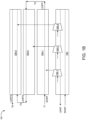
FIG. 1A illustrates an exemplary representation of a multi-channel heat pump comprising a single evaporator connected to multiple series connected condensers having two passes. -
FIG. 1B illustrates an exemplary representation of a multi-channel heat pump comprising a single evaporator connected to multiple series connected condensers having a single pass and two passes. -
FIG. 2 illustrates an exemplary representation of a multi-channel heat pump comprising a condenser having multiple partitioned compartments, each connected to a single evaporator. -
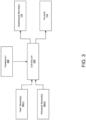
FIG. 3 illustrates an exemplary functional block diagram of the heat pump of any ofFIGs. 1A to 2 . - The following is a detailed description of embodiments of the invention depicted in the accompanying drawings. The embodiments are in such detail as to clearly communicate the invention. However, the amount of detail offered is not intended to limit the anticipated variations of embodiments; on the contrary, the intention is to cover all modifications, equivalents, and alternatives falling within the scope of the invention as defined by the appended claims.
- Various terms are used herein. To the extent a term used in a claim is not defined below, it should be given the broadest definition persons in the pertinent art have given that term as reflected in printed publications and issued patents at the time of filing.
- In the specification, reference may be made to the spatial relationships between various components and to the spatial orientation of various aspects of components as the devices are depicted in the attached drawings. However, as will be recognized by those skilled in the art after a complete reading of the subject disclosure, the components of this invention described herein may be positioned in any desired orientation. Thus, the use of terms such as "above," "below," "upper," "lower," "first", "second" or other like terms to describe a spatial relationship between various components or to describe the spatial orientation of aspects of such components should be understood to describe a relative relationship between the components or a spatial orientation of aspects of such components, respectively, as the heat pump, evaporator, condenser, compartments of condenser, conduit, coil, compressor unit, economizer, and corresponding components, described herein may be oriented in any desired direction.
- Heat pumps are generally employed for district heating, water heating, waste heat recovery, and the like in buildings, and for industrial applications. Existing heat pumps may have a single-unit arrangement including a single condenser fluidically connected to a single evaporator by a compressor. The heat pumps may be of a multiple-unit arrangement including a plurality of the single-units in a series counterflow arrangement, where each unit has a single evaporator fluidically connected to a single condenser by a compressor. The temperature lift in a high-temperature single-unit heat pump may be high, which may result in a high-pressure ratio between the evaporator and the condenser along with a low coefficient of performance (COP). In addition, the series counterflow arrangement may require multiple units each having an evaporator, a condenser, and a compressor, which increases the overall cost, while also being bulky. Thus, there is a need to lower the pressure ratio between the evaporator and condenser and improve the COP of the heat pumps, particularly for high-temperature applications, while keeping the heat pump cost-effective and space-saving.
- Embodiments of this invention provide a simple, improved, efficient, and cost-effective multi-circuit heat pump that has a lower pressure ratio between the evaporator and condenser and an improved coefficient of performance. The heat pump may include a single evaporator fluidically connected to multiple series connected condensers. As a result, the heat pump may involve smaller condensers compared to the condensers involved in the existing single-unit heat pump, which may further allow the use of smaller compressor motors compared to the existing single-unit heat pump for the same capacity. Moreover, for the same capacity, since the condenser in the heat pump may be kept smaller than the condenser of the existing single unit, the stall behavior in the heat pump may be easier to manage. Furthermore, since the evaporator is common for all the condensers in the heat pump, the architecture of the heat pump may have cost and space-saving advantages compared to the existing multiple-unit heat pump.
- Referring to
FIGs. 1A and1B , the multi-circuit heat pump "heat pump" 100 is disclosed. Theheat pump 100 may include a plurality of condensers 104-1 to 104-3 (collectively referred to ascondensers 104, herein) that may be fluidically connected in series. Theheat pump 100 may further include asingle evaporator 102 that may be common for allcondensers 104. Thecommon evaporator 102 may be fluidically connected to each of thecondensers 104 using a plurality of compressor units 106-1 to 106-3 (collectively referred to as compressor unit 106, herein) such that one of the compressor units 106 is fluidically configured between theevaporator 102 and one of thecondensers 104, resulting in multiple circuits with acommon evaporator 102. That is, each compressor unit 106 is fluidically configured between theevaporator 102 and arespective condenser 104. For instance, as illustrated, the compressor 106-1 may be associated withcommon evaporator 102 and the condenser 104-1 in the first circuit, the compressor 106-2 may be associated withcommon evaporator 102 and the condenser 104-2 in the second circuit, and the compressor 106-3 may be associated withcommon evaporator 102 and the condenser 104-3 in the third circuit. Accordingly, multiple circuits may be implemented in theheat pump 100. The compressor unit 106 may include a compressor (also designated as 106, herein) fluidically connected between one of thecondensers 104 and theevaporator 102 and a motor operatively coupled to the compressor 106. Accordingly, the refrigerant from thecommon evaporator 102 may be compressed and delivered to eachcondenser 104 by a separate compressor 106, resulting in multiple circuits with varying temperature lifts. In one or more embodiments, each of the motors may be configured to be operated independently at a predefined speed or rotation per minute (RPM) to independently control the operation of the compressors 106 based on the temperature and pressure of the refrigerant to be maintained in the multiple circuits or components of theheat pump 100. - Each of the
condensers 104 may include a working-fluid conduit "conduit" (shown in dotted lines) having a predefined number of turns and/or passes, disposed within a housing of thecondenser 104. The working-fluid conduit may be configured to allow flow of a working-fluid therethrough. - In one or more embodiments, the working-fluid may be water and the plurality of
condensers 104 may include water-cooled condensers, which may be implemented to heat water and supply the heated or conditioned water to an area of interest (AOI). In other embodiments, the working-fluid may be air and the plurality ofcondensers 104 may include air-cooled condensers, which may be implemented to heat air and supply the heated or conditioned air to an AOI. Further, the working-fluid may be any fluid that may be conditioned by the heat pump. The working-fluid conduit of thecondensers 104 may be in thermal contact with a refrigerant coil (condenser coil) (not shown) associated with thecorresponding condenser 104 within the housing of thecondenser 104. Further, the refrigerant coil of eachcondenser 104 may be fluidically connected to the coils (evaporator coil) of thecommon evaporator 102 via the compressor 106, the economizer, and a piping system in each circuit to enable the flow of the refrigerant between theevaporator 102 and the correspondingcondensers 104, thereby enabling the exchange of heat therebetween and adjusting the temperature of the working-fluid at predefined temperatures indifferent condensers 104. - In one or more embodiments, (not shown in
FIGs. 1A and1B ) theheat pump 100 may include an economizer in each of the circuits. One economizer may be fluidically configured between thecommon evaporator 102, one of thecondensers 104, and the respective compressor in each circuit, thereby forming themulti-circuit heat pump 100. Theheat pump 100 may additionally include (not shown) a filter drier, an accumulator, a receiver, an expansion valve, and the like being configured in each circuit. - An outlet of the conduit associated with the
condensers 104 may be fluidically connected to an inlet of the conduit associated with anadjacent condenser 104 in theheat pump 100 to connect the plurality ofcondensers 104 in series. For instance, as illustrated, the outlet of the conduit associated with the condenser 104-1 may be fluidically connected to an inlet of the conduit associated with the adjacent condenser 104-2, and the outlet of the conduit associated with the condenser 104-2 may be fluidically connected to an inlet of the conduit associated with the adjacent condenser 104-3 in theheat pump 100 to connect the plurality of condensers 104-1 to 104-3 in series. In one or more embodiments, at least one of thecondensers 104 may be a multi-pass condenser or heat exchanger, where the working-fluid conduit has multiple passes. In other embodiments, at least one of thecondensers 104 may be a single-pass condenser or heat exchanger where the working-fluid conduit has a single pass. For instance, as shown inFIG. 1B , the condensers 104-1 and 104-2 may be single-pass condensers, and the condenser 104-3 may be a two-pass condenser. Further, as shown inFIG. 1A , all the condensers 104-1 to 104-3 may be two-pass condensers. - As illustrated in
FIGs. 1A and1B , 'ECWT' may be the condenser water entering the first condenser 104-1, `LCWT1' may be the condenser water leaving the first condenser 104-1, 'LCWT2' may be the condenser water leaving the second condenser 104-2, and 'LCWT3' may be the condenser water leaving the third condenser 104-3. Further, 'EEWT' may be the cool water (fluid) entering theevaporator 102, and 'LEWT' may be the heated water leaving theevaporator 102. Similarly (not shown), in other embodiments, the condensers 104-1 to 104-3 may be air-cooled condensers and air may be circulated through the condensers 104-1 to 104-3 to heat or condition the air. - In one or more embodiments, the outlet of the conduit associated with each of the
condensers 104 may be adapted to facilitate tapping (not shown) of the working-fluid from therespective condensers 104. As themulti-circuit heat pump 100 enables heating of the working-fluid at different temperatures (T1 to T4) in different condensers 104-1 to 104-3, the taps connected to the conduit in each condenser 104-1 to 104-3 may allow users to tap out the working-fluid of the variable temperature range (T1-T4). For instance, as shown inFIGs. 1A and1B , the temperature of the working fluid entering the first condenser 103-1 through the conduit may be T1 (say 60 °C), where the first condenser 104-1 may raise the temperature of the working-fluid to T2 (say 70 °C) and supply the heated working-fluid (say 70 °C) to the inlet of the second condenser 104-2. Further, the second condenser 104-2 may raise the temperature of the working-fluid from T2 (70 °C) to T3 (say 80 °C) and supply the heated working-fluid T3 (80 °C) to the inlet of the third condenser 104-3. Furthermore, the third condenser 104-3 may raise the temperature of the working-fluid from T3 (80 °C) to T4 (say 90 °C) and supply the heated working-fluid T4 (say 90 °C) through the outlet of the third condenser 104-3. Thus, themulti-circuit heat pump 100 allows users to tap out the heated working-fluid in a range of 60 °C to 90 °C. Accordingly, the number ofcondensers 104 in theheat pump 100 may be selected based on the temperature or temperature range of the working-fluid to be achieved using theheat pump 100. - In one or more embodiments, the
heat pump 100 may include additional valves configured with the conduit to control the flow rate and volume of the working-fluid flowing through the conduit indifferent condensers 104 and further allow controlled tapping or outflow of working fluid from eachcondenser 104. In addition, as shown inFIG. 3 , theheat pump 100 may include temperature sensors 304-1 and flow meters/pressure sensors 304-2 to monitor the temperature and pressure of one or more of the working-fluid flowing through thecondensers 104 and the refrigerant flowing through theevaporator 102, compressors 106, andcondensers 104 of theheat pump 100. - In one or more embodiments, the plurality of condensers 104-1 to 104-3 associated with the
heat pump 100 ofFIGs. 1A and1B may be installed as a single condenser unit at an area of interest (AOI) to heat the AOI to a predefined temperature or supply water heated in the predefined temperature range, and the like. In other embodiments, each of the condensers 104-1 to 104-3 associated with theheat pump 100 ofFIGs. 1A and1B may be installed at different locations in the AOI to heat the locations to different predefined temperatures or supply water heated in the predefined temperature range to the locations, but not limited to the like. - Referring to
FIG. 2 , the multi-circuit heat pump "heat pump" 200 including asingle condenser 104 unit having multiple partitioned compartments 202 is disclosed. Theheat pump 200 may be substantially similar toheat pump 100. The common components ofheat pumps heat pump 200 includes asingle condenser 104. Theheat pump 200 may include acondenser 104 having a plurality of compartments 202-1 to 202-3 (collectively referred to as compartments 202, herein) that may be connected in series. Thecondenser 104 may include one or more partition walls 204-1 and 204-2 disposed within the housing of thecondenser 104 to create and physically and thermally isolate the compartments 202-1 to 202-3 in a series arrangement. In addition, each compartment 202 may have a separate refrigerant coil disposed in the housing. Further, a working fluid conduit (shown in dotted line) may extend through the partition walls and the housing of thecondenser 104 to allow the flow of a working-fluid through the compartments 202-1 to 202-3 of thecondenser 104. Theheat pump 200 may further include asingle evaporator 102 that may be common for all the compartments 202. Thecommon evaporator 102 may be fluidically connected to refrigerant coils in each of the compartments 202-1 to 202-3 using a plurality of compressor units 106-1 to 106-2 such that one of the compressor units 106-1 to 106-3 (collectively referred to as compressor units 106, herein) is fluidically configured between theevaporator 102 and one of the compartments 202-1 to 202-3, resulting in multiple circuits with thecommon evaporator 102. That is, each compressor unit 106 is fluidically configured between theevaporator 102 and a respective compartment 202. The compressor unit 106 may include a compressor (also designated as 106, herein) fluidically connected between one of the compartments 202-1 to 202-3 and theevaporator 102 and motors 110-1 to 110-3 (collectively referred to asmotors 110, herein) operatively coupled to the compressors 106-1 to 106-3, respectively. Accordingly, the refrigerant from thecommon evaporator 102 may be compressed and delivered to each compartment 202 by a separate compressor 106, resulting in multiple circuits with varying temperature lifts. In one or more embodiments, each of themotors 110 may be configured to be operated independently at a predefined speed or rotation per minute (RPM) to independently control the operation of the compressors 106-1 to 106-3 based on the temperature and pressure of the refrigerant to be maintained in the multiple circuits or components of theheat pump 200. - In one or more embodiments, the working-fluid conduit of the
condenser 104 may have a predefined number of turns and passes, disposed within the housing of thecondenser 104 and extending through the compartments 202. In one or more embodiments, the working-fluid may be water and thecondenser 104 may be a water-cooled condenser, which may be implemented to heat the water and supply the heated or conditioned water to an area of interest (AOI). In other embodiments, the working-fluid may be air and thecondenser 104 may be an air-cooled condenser, which may be implemented to heat the incoming air and supply heated or conditioned air to an AOI. As illustrated inFIG. 2 , 'ECWT' may be the condenser water entering the first compartment 202-1, 'LCWT1' may be the condenser water leaving the first compartment 202-1, 'LCWT2' may be the condenser water leaving the second compartment 202-2, and 'LCWT3' may be thecondenser 104 water leaving the third compartment 202-3. Further, `EEWT' may be the cool water (fluid) entering theevaporator 102, and 'LEWT' may be the heated water leaving theevaporator 102. Similarly (not shown), in other embodiments, thecondenser 104 may be an air-cooled condenser and air may be circulated through the compartments 202-1 to 202-3 to heat or condition the air. - In one or more embodiments, the
heat pump 200 may include an economizer 108-1 to 108-3 (collectively referred to as economizers 108, herein) in each of the circuits. One economizer 108-1 to 108-3 may be fluidically configured between thecommon evaporator 102, one of the compartments 202-1 to 202-3 of thecondenser 104, and the respective compressor 106-1 to 106-3 in each circuit, thereby forming themulti-circuit heat pump 200. Theheat pump 200 may additionally include (not shown) a filter drier, an accumulator, a receiver, an expansion valve, and the like being configured in each circuit. - The working-fluid conduit of the
condensers 104 may be in thermal contact with the refrigerant coil (condenser coil) (not shown) configured in the corresponding compartments 202 of thecondenser 104. Further, the refrigerant coil of each compartment 202 may be fluidically connected to the coils (evaporator coil) (not shown) of thecommon evaporator 102 via the compressor 106, the economizer 108, and a piping system in each circuit to enable the flow of the refrigerant between the coils of theevaporator 102 and the corresponding compartments 202, thereby enabling the exchange of heat therebetween and adjusting the temperature of the working-fluid at predefined temperatures indifferent condensers 104. - In one or more embodiments, at least one of the compartments 202 of the
condenser 104 may have the working-fluid conduit having multiple passes. In other embodiments, at least one of the compartments 202 of thecondenser 104 may have the working-fluid conduit having a single pass. In one or more embodiments, theheat pump 200 may include additional valves (not shown) configured with the conduit to control the flow rate and volume of the working-fluid flowing through the conduit in different compartments 202 and further allow controlled tapping or outflow of working fluid from each compartment. In addition, as shown inFIG. 3 , theheat pump 200 may include temperature sensors 304-1 and flow meters 304-2 to monitor the temperature and pressure of one or more of the working-fluid flowing through the compartments 202 and the refrigerant flowing through theevaporator 102, compressor 106, and compartments 202 of theheat pump 200. - In one or more embodiments, (not shown) a section of the conduit in each compartment of the
condensers 104 may be adapted to facilitate tapping (not shown) of the working-fluid from the respective compartment 202. As themulti-circuit heat pump 200 enables heating of the working-fluid at different temperatures in different compartments 202, the taps connected to the conduit in each compartment may allow users to tap out working-fluid of the variable temperature range. For instance, but not limited to the like, the temperature of the working fluid entering the first compartment 202-1 may be at T1 (say 60 °C), where the first compartment may raise the temperature of the working-fluid to T2 (say 70 °C) and supply the heated working-fluid T2 (70 °C) to the second compartment 202-2. Further, the second compartment 202-2 may raise the temperature of the working-fluid from T2 (70 °C) to T3 (say 80 °C) and supply the heated working-fluid T3 (80 °C) to the third compartment 202-3. Furthermore, the third compartment 202-3 may raise the temperature of the working-fluid from T3 (80 °C) to T4 (say 90 °C) and supply the heated working-fluid (90 °C) through the outlet of the third compartment 202-3. Thus, themulti-circuit heat pump 200 allows users to tap out heated working-fluid in a range of T1 (60 °C) to T4 (90 °C). Accordingly, the number of compartments 202 in thecondenser 104 may be selected based on the temperature or temperature range T1 to T4 of the working-fluid to be achieved using theheat pump 200. - Referring to
FIG. 3 , theheat pumps FIGs. 1A and2 , may include acontroller 302 operatively coupled to one or more of themotors 110 of the compressor units 106, thecommon evaporator 102, and the condenser(s) 104. Thecontroller 302 may include a processor operatively coupled to a memory storing instructions executable by the processor to enable thecontroller 302 to perform one or more designated operations. Thecontroller 302 may be in communication with the temperature sensors 304-1 and flow meters/pressure sensors 304-2 installed in theheat pump heat pump controller 302 may be in further communication with athermostat 306 provided at the AOI where theheat pump controller 302 may receive, from thethermostat 306 or mobile devices of the users, a set of instructions pertaining to the temperature of air or temperature of working-fluid (water or air) to be provided or maintained at the AOI. Thecontroller 302 may accordingly independently actuate the different compressors 106 andvalves 112 associated with the heat pump to independently operate the compressors 106 at different or same RPM to compress refrigerant received from theevaporator 102 and further enable the supply of the compressed refrigerant to the condenser(s) 104 and supply of the refrigerant from the condenser(s) 104 back to theevaporator 102 or economizer 108, to heat the working-fluid at user-defined temperature or temperature range at the condenser end. - The
controller 302 is configured to independently operate themotors 110 of the compressor units 106 associated with each of thecondensers 104 based on the temperature of the working-fluid to be maintained in and tapped from the conduit across each of the condensers, and/or based on temperature to be maintained across each of thecondensers 104 or compartments 202, and/or based on a pressure ratio to be maintained between theevaporator 102 and each of thecondensers 104. - The number of condensers in the
heat pump 100 ofFIGs. 1A and1B and/or the number of compartments 202 in the condenser of theheat pump 200 ofFIG. 2 may be selected based on COP to be achieved and the temperature or temperature range of the working-fluid (water/air) to be maintained using theheat pump heat pump condensers 104 inFIG. 2 or the different number of compartments 202 in thecondenser 104 ofFIG. 2 is shown in the Table below.TABLE No of compartments/ No. of condensers COP (%) 1 (Existing Single unit heat pump) 2.37 2 2.61 3 2.7 4 2.74 5 2.74 6 2.74 - Thus, the
heat pump FIGs. 1A and2 provides a simple, improved, efficient, and cost-effective multi-circuit heat pump that has a lower pressure ratio between the evaporator and condenser and an improved coefficient of performance. As the heat pump includes a single evaporator fluidically connected to multiple condensers or compartments that are connected in series, as a result, the heat pump involves smaller condensers compared to the condensers involved in the existing single-unit heat pump. This may further allow the use of smaller compressor motors compared to the existing single-unit heat pump for the same capacity. In addition, for the same capacity, as the condenser in the heat pump may be kept smaller than the condenser of the existing single unit, the stall behavior in the heat pump is also easier to manage. Further, since the evaporator is common for all the condensers in the heat pump, the architecture of the heat pump has cost and space-saving advantages compared to the existing multiple-unit heat pump. Furthermore, in an event of failure of any of the condensers, the remaining healthy condensers may operate with reduced load, while keeping the overall heat pump active. - While the invention has been described with reference to exemplary embodiments, it will be understood by those skilled in the art that various changes may be made and equivalents may be substituted for elements thereof without departing from the scope of the invention as defined by the appended claims. Modifications may be made to adopt a particular situation or material to the teachings of the invention without departing from the scope thereof. Therefore, it is intended that the invention not be limited to the particular embodiment disclosed, but that the invention includes all embodiments falling within the scope of the invention as defined by the appended claims.
- In interpreting the specification, all terms should be interpreted in the broadest possible manner consistent with the context. In particular, the terms "comprises" and "comprising" should be interpreted as referring to elements, components, or steps in a non-exclusive manner, indicating that the referenced elements, components, or steps may be present, or utilized, or combined with other elements, components, or steps that are not expressly referenced. Where the specification claims refer to at least one of something selected from the group consisting of A, B, C ....and N, the text should be interpreted as requiring only one element from the group, not A plus N, or B plus N, etc.
Claims (15)
- A multi-circuit heat pump (100) comprising:an evaporator (102);a plurality of condensers (104-1, 104-2, 104-3) fluidically connected in series; anda plurality of compressor units (106-1, 106-2, 106-3) configured between the evaporator and the plurality of condensers such that one of the compressor units is fluidically configured between the evaporator and one of the condensers.
- The heat pump of claim 1, wherein each of the compressor units (106-1, 106-2, 160-3) comprises a compressor operatively coupled to a motor, wherein each of the motors is configured to be independently operated at a predefined speed.
- The heat pump of claim 1 or 2, wherein the heat pump (100) comprises a plurality of economizers, wherein one of the economizers is fluidically configured between the evaporator (102), one of the condensers (104-1, 104-2, 104-3), and the respective compressor (106-1, 106-2, 106-3).
- The heat pump of any preceding claim, wherein at least one of the plurality of condensers (104-1, 104-2, 104-3) is a multi-pass heat exchanger; and/or
wherein at least one of the plurality of condensers (104-1, 104-2, 104-3) is a single-pass heat exchanger. - The heat pump of any preceding claim, wherein each of the condensers (104-1, 104-2, 104-3) comprises a conduit having a predefined number of turns and passes, disposed within a housing of the condenser and in thermal contact with a refrigerant coil associated with the corresponding condenser, wherein the conduit is configured to facilitate flow of a working-fluid therethrough.
- The heat pump of claim 5, wherein an outlet of the conduit associated with one of the condensers (104-1, 104-2, 104-3) is fluidically connected to an inlet of the conduit associated with an adjacent condenser to connect the plurality of condensers in series; and/or
wherein an outlet of the conduit associated with each of the condensers (104-1, 104-2, 104-3) is adapted to facilitate tapping of the working-fluid from the respective condensers. - The heat pump of claim 2, or any of claims 3 to 6 when dependent upon claim 2, wherein the heat pump (100) comprises a controller (302) operatively coupled to one or more of the motors of the compressor unit (106-1, 106-2, 106-3), the evaporator (102), and the plurality of condensers (104-1, 104-2, 104-3),
wherein the controller is configured to independently operate the motor of the compressor unit associated with each of the condensers based on temperature of the working-fluid to be maintained in and tapped from the conduit across each of the condensers. - The heat pump of any preceding claim, wherein the working-fluid is water and the plurality of condensers (104-1, 104-2, 104-3) are water-cooled condensers; or
wherein the working-fluid is air and the plurality of condensers (104-1, 104-2, 104-3) are air-cooled condensers. - A multi-circuit heat pump (200) comprising:an evaporator (102);a condenser (104) comprising a housing having a plurality of compartments (202-1, 202-2, 202-3) isolated from each other and arranged in series within the housing, wherein each of the compartments comprises a refrigerant coil; anda plurality of compressor units (106-1, 106-2, 106-3) configured between the evaporator and the plurality of compartments of the condenser such that one of the compressor units is fluidically configured between the evaporator (102) and one of the compartments (202-1, 202-2, 202-3).
- The heat pump of claim 9, wherein each of the compressor units (106-1, 106-2, 106-3) comprises a compressor operatively coupled to a motor (110-1, 110-2, 110-3), wherein each of the motors is configured to be independently operated at a predefined speed.
- The heat pump of claim 9 or 10, wherein the heat pump (200) comprises a plurality of economizers (108-1, 108-2, 108-3), wherein one of the economizers is fluidically configured between the evaporator (102), one of the compartments (202-1, 202-2, 202-3), and the respective compressor (106-1, 106-2, 106-3).
- The heat pump of any of claims 9 to 11, wherein the condenser (104) comprises a conduit having a predefined number of turns and passes disposed of within the housing and extending through each of the compartments (202-1, 202-2, 202-3), wherein the conduit is in thermal contact with the refrigerant coil of each of the compartments and configured to facilitate flow of a working-fluid therethrough; optionally wherein the conduit is adapted to facilitate tapping of the working-fluid from each of the compartments (202-1, 202-2, 202-3).
- The heat pump of claim 12, wherein the condenser (104) comprises one or more partition walls disposed of within the housing to create and isolate the plurality of compartments (202-1, 202-2, 202-3), wherein the conduit extends through the one or more partition walls.
- The heat pump of claim 10, or any of claims 11 to 13 when dependent upon claim 10, wherein the heat pump (200) comprises a controller (302) operatively coupled to one or more of the motors (110-1, 110-2, 110-3) of the compressor unit (106-1, 106-2, 106-3), the evaporator (102), and the condenser (104),
wherein the controller is configured to independently operate the motor of the compressor unit associated with each of the compartments (202-1, 202-2, 202-3) based on temperature of the working-fluid to be maintained in and tapped from the conduit across each of the compartments. - The heat pump of any of claims 9 to 14, wherein the working-fluid is water and the condenser (104) is a water-cooled condenser; or
wherein the working-fluid is air and the condenser (104) is an air-cooled condenser.
Applications Claiming Priority (1)
| Application Number | Priority Date | Filing Date | Title |
|---|---|---|---|
| US202363508967P | 2023-06-19 | 2023-06-19 |
Publications (1)
| Publication Number | Publication Date |
|---|---|
| EP4495501A1 true EP4495501A1 (en) | 2025-01-22 |
Family
ID=91586013
Family Applications (1)
| Application Number | Title | Priority Date | Filing Date |
|---|---|---|---|
| EP24182880.5A Pending EP4495501A1 (en) | 2023-06-19 | 2024-06-18 | Multi-circuit heat pump |
Country Status (3)
| Country | Link |
|---|---|
| US (1) | US20240418415A1 (en) |
| EP (1) | EP4495501A1 (en) |
| CN (1) | CN119164117A (en) |
Citations (3)
| Publication number | Priority date | Publication date | Assignee | Title |
|---|---|---|---|---|
| DE102017100591B3 (en) * | 2017-01-13 | 2018-05-09 | Hanon Systems | Refrigerant circuit, in particular for motor vehicles with electric or hybrid drive and method for operating the refrigerant circuit |
| EP2699853B1 (en) * | 2011-04-21 | 2019-03-13 | Carrier Corporation | Transcritical refrigerant vapor system with capacity boost |
| US20220333834A1 (en) * | 2019-07-15 | 2022-10-20 | Johnson Controls Tyco IP Holdings LLP | Chiller system with multiple compressors |
Family Cites Families (6)
| Publication number | Priority date | Publication date | Assignee | Title |
|---|---|---|---|---|
| DE3565718D1 (en) * | 1984-09-19 | 1988-11-24 | Toshiba Kk | Heat pump system |
| US6694750B1 (en) * | 2002-08-21 | 2004-02-24 | Carrier Corporation | Refrigeration system employing multiple economizer circuits |
| KR101873597B1 (en) * | 2012-02-23 | 2018-07-31 | 엘지전자 주식회사 | An air conditioner |
| US10520235B2 (en) * | 2016-12-09 | 2019-12-31 | Lennox Industries Inc. | Method to avoid fan cycling during low ambient operation |
| US11162723B2 (en) * | 2019-03-29 | 2021-11-02 | Trane International Inc. | Methods and systems for controlling working fluid in HVACR systems |
| EP4685416A1 (en) * | 2024-07-10 | 2026-01-28 | Vertiv Corporation | Mixed mode modular cooling system and operating method thereof |
-
2024
- 2024-06-10 US US18/738,111 patent/US20240418415A1/en active Pending
- 2024-06-18 EP EP24182880.5A patent/EP4495501A1/en active Pending
- 2024-06-18 CN CN202410784715.4A patent/CN119164117A/en active Pending
Patent Citations (3)
| Publication number | Priority date | Publication date | Assignee | Title |
|---|---|---|---|---|
| EP2699853B1 (en) * | 2011-04-21 | 2019-03-13 | Carrier Corporation | Transcritical refrigerant vapor system with capacity boost |
| DE102017100591B3 (en) * | 2017-01-13 | 2018-05-09 | Hanon Systems | Refrigerant circuit, in particular for motor vehicles with electric or hybrid drive and method for operating the refrigerant circuit |
| US20220333834A1 (en) * | 2019-07-15 | 2022-10-20 | Johnson Controls Tyco IP Holdings LLP | Chiller system with multiple compressors |
Also Published As
| Publication number | Publication date |
|---|---|
| CN119164117A (en) | 2024-12-20 |
| US20240418415A1 (en) | 2024-12-19 |
Similar Documents
| Publication | Publication Date | Title |
|---|---|---|
| US12578124B2 (en) | Integrated demand water heating using a capacity modulated heat pump with desuperheater | |
| US11175076B2 (en) | Free cooling refrigeration system | |
| JP6692442B2 (en) | System and method for controlling a cooling system | |
| US9316424B2 (en) | Multi-stage cooling system with tandem compressors and optimized control of sensible cooling and dehumidification | |
| US4041724A (en) | Installation for heating a fluid, preferably water, in a conventional central heating system, using the waste heat produced by a number of refrigerators | |
| US3938352A (en) | Water to air heat pump employing an energy and condensate conservation system | |
| US7024877B2 (en) | Water heating system | |
| JP2005140444A (en) | Air conditioner and control method thereof | |
| CA2593405A1 (en) | Hvac system with powered subcooler | |
| WO2010005918A2 (en) | Heat pump with microchannel heat exchangers as both outdoor and reheat heat exchangers | |
| EP3308085A1 (en) | Cooling system with direct expansion and pumped refrigerant economization cooling | |
| WO2014055914A1 (en) | Load estimator for control of vapor compression cooling system with pumped refrigerant economization | |
| EP3354996B1 (en) | Chiller plant with ice storage | |
| US20220049886A1 (en) | Methods and systems for controlling working fluid in hvacr systems | |
| US4057977A (en) | Reverse cycle heat pump circuit | |
| EP4301103A1 (en) | Modular cooling system | |
| US20240418415A1 (en) | Multi-circuit heat pump | |
| JPS6273050A (en) | Heat pump system and installation method thereof | |
| EP3674622B1 (en) | Fluid control for a variable flow fluid circuit of a unit in an hvacr system | |
| JP6608353B2 (en) | Temperature control system | |
| JP2013124843A (en) | Refrigeration cycle system | |
| JP2025520202A (en) | Low charge chiller and free cooling | |
| JP2011196629A (en) | Multi-room type air conditioning device | |
| EP4150265B1 (en) | Cooling system | |
| JP2006046782A (en) | Air conditioner and method of operating air conditioner |
Legal Events
| Date | Code | Title | Description |
|---|---|---|---|
| PUAI | Public reference made under article 153(3) epc to a published international application that has entered the european phase |
Free format text: ORIGINAL CODE: 0009012 |
|
| STAA | Information on the status of an ep patent application or granted ep patent |
Free format text: STATUS: THE APPLICATION HAS BEEN PUBLISHED |
|
| AK | Designated contracting states |
Kind code of ref document: A1 Designated state(s): AL AT BE BG CH CY CZ DE DK EE ES FI FR GB GR HR HU IE IS IT LI LT LU LV MC ME MK MT NL NO PL PT RO RS SE SI SK SM TR |
|
| STAA | Information on the status of an ep patent application or granted ep patent |
Free format text: STATUS: REQUEST FOR EXAMINATION WAS MADE |
|
| 17P | Request for examination filed |
Effective date: 20250721 |