EP4495476A1 - Light source unit for vehicular lighting fixture, and vehicular lighting fixture - Google Patents
Light source unit for vehicular lighting fixture, and vehicular lighting fixture Download PDFInfo
- Publication number
- EP4495476A1 EP4495476A1 EP23770538.9A EP23770538A EP4495476A1 EP 4495476 A1 EP4495476 A1 EP 4495476A1 EP 23770538 A EP23770538 A EP 23770538A EP 4495476 A1 EP4495476 A1 EP 4495476A1
- Authority
- EP
- European Patent Office
- Prior art keywords
- light sources
- light source
- lighting fixture
- source unit
- vehicular lighting
- Prior art date
- Legal status (The legal status is an assumption and is not a legal conclusion. Google has not performed a legal analysis and makes no representation as to the accuracy of the status listed.)
- Pending
Links
Images



Classifications
-
- F—MECHANICAL ENGINEERING; LIGHTING; HEATING; WEAPONS; BLASTING
- F21—LIGHTING
- F21S—NON-PORTABLE LIGHTING DEVICES; SYSTEMS THEREOF; VEHICLE LIGHTING DEVICES SPECIALLY ADAPTED FOR VEHICLE EXTERIORS
- F21S43/00—Signalling devices specially adapted for vehicle exteriors, e.g. brake lamps, direction indicator lights or reversing lights
- F21S43/10—Signalling devices specially adapted for vehicle exteriors, e.g. brake lamps, direction indicator lights or reversing lights characterised by the light source
- F21S43/13—Signalling devices specially adapted for vehicle exteriors, e.g. brake lamps, direction indicator lights or reversing lights characterised by the light source characterised by the type of light source
- F21S43/14—Light emitting diodes [LED]
-
- F—MECHANICAL ENGINEERING; LIGHTING; HEATING; WEAPONS; BLASTING
- F21—LIGHTING
- F21S—NON-PORTABLE LIGHTING DEVICES; SYSTEMS THEREOF; VEHICLE LIGHTING DEVICES SPECIALLY ADAPTED FOR VEHICLE EXTERIORS
- F21S43/00—Signalling devices specially adapted for vehicle exteriors, e.g. brake lamps, direction indicator lights or reversing lights
- F21S43/10—Signalling devices specially adapted for vehicle exteriors, e.g. brake lamps, direction indicator lights or reversing lights characterised by the light source
- F21S43/19—Attachment of light sources or lamp holders
- F21S43/195—Details of lamp holders, terminals or connectors
-
- F—MECHANICAL ENGINEERING; LIGHTING; HEATING; WEAPONS; BLASTING
- F21—LIGHTING
- F21S—NON-PORTABLE LIGHTING DEVICES; SYSTEMS THEREOF; VEHICLE LIGHTING DEVICES SPECIALLY ADAPTED FOR VEHICLE EXTERIORS
- F21S43/00—Signalling devices specially adapted for vehicle exteriors, e.g. brake lamps, direction indicator lights or reversing lights
- F21S43/20—Signalling devices specially adapted for vehicle exteriors, e.g. brake lamps, direction indicator lights or reversing lights characterised by refractors, transparent cover plates, light guides or filters
- F21S43/255—Filters
-
- F—MECHANICAL ENGINEERING; LIGHTING; HEATING; WEAPONS; BLASTING
- F21—LIGHTING
- F21S—NON-PORTABLE LIGHTING DEVICES; SYSTEMS THEREOF; VEHICLE LIGHTING DEVICES SPECIALLY ADAPTED FOR VEHICLE EXTERIORS
- F21S43/00—Signalling devices specially adapted for vehicle exteriors, e.g. brake lamps, direction indicator lights or reversing lights
- F21S43/20—Signalling devices specially adapted for vehicle exteriors, e.g. brake lamps, direction indicator lights or reversing lights characterised by refractors, transparent cover plates, light guides or filters
- F21S43/2605—Refractors
- F21S43/2621—Refractors characterised by the properties of the light beam shaping surface
- F21S43/26231—Refractors characterised by the properties of the light beam shaping surface collimating, focusing, condensing or projecting beams, e.g. projection lenses or Fresnel lenses
-
- F—MECHANICAL ENGINEERING; LIGHTING; HEATING; WEAPONS; BLASTING
- F21—LIGHTING
- F21S—NON-PORTABLE LIGHTING DEVICES; SYSTEMS THEREOF; VEHICLE LIGHTING DEVICES SPECIALLY ADAPTED FOR VEHICLE EXTERIORS
- F21S43/00—Signalling devices specially adapted for vehicle exteriors, e.g. brake lamps, direction indicator lights or reversing lights
- F21S43/20—Signalling devices specially adapted for vehicle exteriors, e.g. brake lamps, direction indicator lights or reversing lights characterised by refractors, transparent cover plates, light guides or filters
- F21S43/27—Attachment thereof
-
- F—MECHANICAL ENGINEERING; LIGHTING; HEATING; WEAPONS; BLASTING
- F21—LIGHTING
- F21S—NON-PORTABLE LIGHTING DEVICES; SYSTEMS THEREOF; VEHICLE LIGHTING DEVICES SPECIALLY ADAPTED FOR VEHICLE EXTERIORS
- F21S45/00—Arrangements within vehicle lighting devices specially adapted for vehicle exteriors, for purposes other than emission or distribution of light
- F21S45/40—Cooling of lighting devices
- F21S45/47—Passive cooling, e.g. using fins, thermal conductive elements or openings
- F21S45/48—Passive cooling, e.g. using fins, thermal conductive elements or openings with means for conducting heat from the inside to the outside of the lighting devices, e.g. with fins on the outer surface of the lighting device
-
- F—MECHANICAL ENGINEERING; LIGHTING; HEATING; WEAPONS; BLASTING
- F21—LIGHTING
- F21S—NON-PORTABLE LIGHTING DEVICES; SYSTEMS THEREOF; VEHICLE LIGHTING DEVICES SPECIALLY ADAPTED FOR VEHICLE EXTERIORS
- F21S45/00—Arrangements within vehicle lighting devices specially adapted for vehicle exteriors, for purposes other than emission or distribution of light
- F21S45/40—Cooling of lighting devices
- F21S45/47—Passive cooling, e.g. using fins, thermal conductive elements or openings
-
- F—MECHANICAL ENGINEERING; LIGHTING; HEATING; WEAPONS; BLASTING
- F21—LIGHTING
- F21W—INDEXING SCHEME ASSOCIATED WITH SUBCLASSES F21K, F21L, F21S and F21V, RELATING TO USES OR APPLICATIONS OF LIGHTING DEVICES OR SYSTEMS
- F21W2103/00—Exterior vehicle lighting devices for signalling purposes
- F21W2103/60—Projection of signs from lighting devices, e.g. symbols or information being projected onto the road
-
- F—MECHANICAL ENGINEERING; LIGHTING; HEATING; WEAPONS; BLASTING
- F21—LIGHTING
- F21Y—INDEXING SCHEME ASSOCIATED WITH SUBCLASSES F21K, F21L, F21S and F21V, RELATING TO THE FORM OR THE KIND OF THE LIGHT SOURCES OR OF THE COLOUR OF THE LIGHT EMITTED
- F21Y2115/00—Light-generating elements of semiconductor light sources
- F21Y2115/10—Light-emitting diodes [LED]
Definitions
- the present invention relates to a light source unit for a vehicular lighting fixture, and a vehicular lighting fixture.
- LEDs light emitting diodes
- the number of configurations that use light emitting elements such as LEDs as light sources has been gradually increasing.
- LEDs have the merits of long life and low power consumption. Meanwhile, since high temperatures lead to a decrease in light emitting efficiency and reduction in lifespan, it is necessary to use a heat sink to efficiently dissipate the heat generated by LEDs to the outside.
- Patent Document 1 discloses a light source unit in which a circuit board on which an LED and a driving circuit configured to drive the LED are mounted is attached to a heatsink, and a coupler socket integrally attached to a connector part that electrically connects the heatsink to the circuit board is detachably attached to an attachment hole provided in a lighting body on a back surface side.
- Patent Document 1 Japanese Unexamined Patent Application, First Publication No. 2021-111465
- An aspect of the present invention is directed to providing a light source unit for a vehicular lighting fixture capable of increasing utilization efficiency of light when road surface drawing is performed, and a vehicular lighting fixture including such a light source unit for a vehicular lighting fixture.
- An aspect of the present invention provides the following configurations.
- a light source unit for a vehicular lighting fixture capable of increasing utilization efficiency of light when road surface drawing is performed, and a vehicular lighting fixture including such a light source unit for a vehicular lighting fixture.
- a vehicular lighting fixture 100 including a light source unit for a vehicular lighting fixture (hereinafter referred to as "a light source unit") 1 shown in FIG. 1 will be described.
- FIG. 1 is a cross-sectional view showing a configuration of the vehicular lighting fixture 100 including the light source unit 1.
- an XYZ orthogonal coordinate system is set, an X-axis direction indicates a forward/rearward direction (a lengthwise direction) of the light source unit 1 (the vehicular lighting fixture 100), a Y-axis direction indicates a leftward/rightward direction (a widthwise direction) of the light source unit 1 (the vehicular lighting fixture 100), and a Z-axis direction indicates an upward/downward direction (a height direction) of the light source unit 1 (the vehicular lighting fixture 100).
- the vehicular lighting fixture 100 of the embodiment includes, for example, the light source unit 1 configured to perform road surface drawing using light projected onto a road surface when a vehicle (not shown) moves rearward, as a part of back lamps mounted on both corner portions of the vehicle on the side of a rear end.
- directions of "forward,” “rearward,” “leftward,” “rightward,” “upward” and “downward” are not particularly limited, and are directions when the vehicular lighting fixture 100 (the light source unit 1) is seen from a front side (behind the vehicle). Accordingly, directions when the vehicle is viewed from the front side (in front of the vehicle) are directions which are opposite to the above-mentioned forward, rearward, leftward and rightward directions.
- the vehicular lighting fixture 100 has a configuration in which the light source unit 1 of the embodiment is accommodated in a lighting body 103 constituted by a housing 101, a front side (front surface) of which is opened, and a transparent lens cover 102 configured to cover the opening of the housing 101.
- the light source unit 1 can be detachably attached to a periphery of the attachment hole 101a via a ring-shaped packing (O ring) 104 in a state in which a front surface side of the light source unit is inserted inside of the lighting body 103 from an attachment hole 101a provided in the housing 101 (the lighting body 103) on a back surface (rear surface) side, as an exchangeable (replaceable) coupler socket.
- a ring-shaped packing (O ring) 104 in a state in which a front surface side of the light source unit is inserted inside of the lighting body 103 from an attachment hole 101a provided in the housing 101 (the lighting body 103) on a back surface (rear surface) side, as an exchangeable (replaceable) coupler socket.
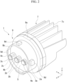
- FIG. 2 is a perspective view showing a configuration of the light source unit 1.
- FIG. 3 is a cross-sectional view showing a configuration of the light source unit 1.
- FIG. 4 is a perspective view showing a shape when a drawing pattern, which is obtained by reflecting a shape formed by emission of a plurality of light sources from the light source unit 1, is projected onto a road surface using a plurality of lens bodies.
- FIG. 5 is a plan view showing a shape when a drawing pattern obtained by reflecting a shape formed by emission of the plurality of light sources is projected onto a road surface using the plurality of lens bodies as a part of back lamps from the light source unit 1.
- FIG. 6 is a plan view showing a shape when a drawing pattern obtained by reflecting a shape formed by emission of the plurality of light sources is projected onto a road surface using the plurality of lens bodies as a part of turn lamps from the light source unit 1.
- FIG. 7 is a perspective view showing another configuration of a light source unit 1A.
- the light source unit 1 of the embodiment includes a plurality of (in the embodiment, three) light sources 2a, 2b and 2c, a plurality of (in the embodiment, three) lens bodies 3a, 3b and 3c disposed in front of the plurality of light sources 2a, 2b and 2c, respectively, a plurality of (in the embodiment, three) lens holding parts 4a, 4b and 4c configured to hold the lens bodies 3a, 3b and 3c in front of the light sources 2a, 2b and 2c while surrounding the light sources 2a, 2b and 2c, respectively, a circuit board 5 on which the plurality of light sources 2a, 2b and 2c are mounted, a heatsink 7 configured to radiate heat emitted from the plurality of light sources 2a, 2b and 2c to the outside via a board attachment part 6 to which the circuit board 5 is attached, and a socket body 9 configured integrally with the heatsink 7 and having a connector part 8 electrically connected to the circuit
- the plurality of light sources 2a, 2b and 2c are constituted by light emitting diodes (LEDs) configured to emit white light (hereinafter referred to as "light") L1, L2 and L3, respectively.
- the plurality of light sources 2a, 2b and 2c are mounted on one surface (in the embodiment, a front surface) side of the circuit board 5 on which a driving circuit (not shown) configured to drive the LEDs is provided, and are arranged at equal intervals in one direction (in the embodiment, the widthwise direction) in the surface of the circuit board 5. Accordingly, each of the light sources 2a, 2b and 2c radially emits the light L1, L2 and L3 forward (toward a +X axis).
- the plurality of lens holding parts 4a, 4b and 4c are formed of, for example, a cylindrical white resin, and attached to one surface side of the circuit board 5 while surrounding the light sources 2a, 2b and 2c, respectively.
- the plurality of lens bodies 3a, 3b and 3c are constituted by convex lenses obtained by adjusting focal distances such that rear focuses thereof coincide with the light sources 2a, 2b and 2c or the vicinity thereof, and attached to front sides of the lens holding parts 4a, 4b and 4c, respectively.
- the plurality of lens bodies 3a, 3b and 3c are disposed for each of the light sources 2a, 2b and 2c arranged in one direction, respectively, in a state distances T1, T2 and T3 between the light sources 2a, 2b and 2c and the lens bodies 3a, 3b and 3c are different from each other for each of the light sources 2a, 2b and 2c.
- a distance between the light source 2a and the lens body 3a located on one end side in one direction is set as T1
- a distance between the light source 2b and the lens body 3b located in the middle of the one direction is set as T2
- a distance between the light source 2c and the lens body 3c located on the other end side in the one direction is set as T3
- T1 ⁇ T2 ⁇ T3 is satisfied.
- light gathering power of the plurality of lens bodies 3a, 3b and 3c is relatively higher as the distances T1, T2 and T3 to the light sources 2a, 2b and 2c from the plurality of lens bodies 3a, 3b and 3c become larger. That is, as the distances T1, T2 and T3 to the light sources 2a, 2b and 2c from the plurality of lens bodies 3a, 3b and 3c are increased, the lights L1, L2 and L3 emitted from the light sources 2a, 2b and 2c can be projected in a more forward.
- the light source unit 1 has a structure in which the heatsink 7 and the socket body 9 are integrated by insert-molding the heatsink 7 and the socket body 9 together. Further, the light source unit 1 may have a structure in which the heatsink 7 and the socket body 9, which are formed separately, are integrated together with a screw or the like.
- the heatsink 7 is formed of a metal material having high thermal conductivity, for example, aluminum (Al), iron (Fe), copper (Cu), or the like.
- the socket body 9 is formed of an insulating resin material, for example, polyethylene terephthalate (PET), polybutylene terephthalate (PBT), polyamide (PA), or the like.
- the socket body 9 may be made of resin to which a filler with high thermal conductivity, such as carbon, ceramic, metal, or the like, has been added.
- the heatsink 7 has a substantially disk-shaped base part 7a, a protrusion part 7b protruding from a substantially central part of the base part 7a on a front surface side in a substantially rectangular cross-sectional shape, and a plurality of radiating fins 7c protruding from a rear surface side of the base part 7a in a longitudinal plate shape while being arranged in the widthwise direction.
- the socket body 9 has a substantially disk-shaped base part 9a, a cylindrical wall part 9b protruding forward from a substantially central part of the base part 9a on a front surface side in a substantially circular cross-sectional shape, and a through-hole 9c formed in the cylindrical wall part 9b and passing through the base part 9a in the forward/rearward direction in a substantially rectangular cross-sectional shape.
- the outer circumferential surface of the cylindrical wall part 9b is provided with a plurality of claw portions 9d arranged in a circumferential direction so as to act as anti-rotation and anti-fall-out members for the attachment hole 101a of the housing 101.
- the packing 104 is attached while passing through the cylindrical wall part 9b and being in contact with the base part 9a.
- the socket body 9 has a through-hole 9e located below the through-hole 9c and passing through a cylindrical wall part 8b and the base part 9a in the forward/rearward direction, and a substantially rectangular cylindrical fitting portion 9f protruding rearward from a periphery of the through-hole 9e of the base part 9a on a back surface side.
- the connector part 8 has a plurality of lead terminals 10. Each of the lead terminals 10 is integrally attached to the main body portion 8a while passing through a main body portion 8a of the connector part 8 in the forward/rearward direction.
- the connector part 8 is configured to fit the main body portion 8a into the through-hole 9e such that the lead terminals 10 are located inside the fitting portion 9f.
- the plurality of lead terminals 10 is fixed to a land portion in the periphery of each of a plurality of hole portions 5a by soldering while passing through the hole portions 5a that pass through the circuit board 5 in a thickness direction. Accordingly, the plurality of lead terminals 10 are electrically connected to the circuit board 5.
- the board attachment part 6 is provided on an inner front surface of the cylindrical wall part 9b.
- the heatsink 7 and the socket body 9 are integrated by fitting the protrusion part 7b into the through-hole 9c and butting the base parts 7a and 9a against each other.
- a sealing member 11 is disposed between a tip of the protrusion part 7b and the through-hole 9c to hermetically seal a space therebetween. Accordingly, in the board attachment part 6, the tip of the protrusion part 7b exposed from the through-hole 9c forms a flat surface continuous with the inner front surface of the cylindrical wall part 9b.
- the circuit board 5 is attached to the front surface of the board attachment part 6 via thermally conductive adhesive 12. Accordingly, the circuit board 5 is thermally connected to the heatsink 7 via the protrusion part 7b that constitutes a part of the thermally conductive adhesive 12 and the board attachment part 6. Meanwhile, the circuit board 5 is electrically insulated from the heatsink 7 in this state.
- the rectangular drawing patterns P1, P2 and P3 extending toward the side in front of the road surface T and having widths that are gradually increased are formed next to each other in the forward/rearward direction of the road surface T.
- the distance projected from the plurality of light sources 2a, 2b and 2c to the road surface T is sufficiently larger than the interval between the plurality of adjacent light sources 2a, 2b and 2c, it is possible to almost ignore the center shift in the widthwise direction of the drawing patterns P1, P2 and P3 aligned in the forward/rearward directions of the road surface T.
- road surface drawing can be performed while projecting the plurality of drawing patterns P1, P2 and P3 toward the road surface T when the vehicle moves rearward.
- the light source unit 1 of the embodiment by projecting the drawing patterns P1, P2 and P3 by the lights L1, L2 and L3 emitted from the plurality of light sources 2a, 2b and 2c toward the road surface T using the plurality of lens bodies 3a, 3b and 3c, utilization efficiency of the lights L1, L2 and L3 when road surface drawing is performed can be increased.
- the light source unit 1 of the embodiment as light gathering power of the lens bodies 3a, 3b and 3c becomes relatively higher as the distances T1, T2 and T3 to the light sources 2a, 2b and 2c from the lens bodies 3a, 3b and 3c are increased, brightness (illuminance) of the drawing patterns P1, P2 and P3 can be made uniform regardless of the distance where the light is projected toward the road surface T from the plurality of light sources 2a, 2b and 2c.
- road surface drawing can also be performed by projecting the drawing patterns P1, P2 and P3 by orange lights L1, L2 and L3 emitted from the plurality of light sources 2a, 2b and 2c toward the road surface T next to each other in the forward/rearward direction using the plurality of lens bodies 3a, 3b and 3c.
- the plurality of drawing patterns P1, P2 and P3 projected onto the road surface T can alert motorcycles, pedestrians, and the like, in the blind spot of the vehicle B that vehicle B is going to turn.
- the drawing patterns P1, P2 and P3 obtained by reflecting the shape formed by emission of the plurality of light sources 2a, 2b and 2c are projected toward the road surface T, for example, like the light source unit 1A shown in FIG.
- a filter 13 having a transmissive area (in the embodiment, a slit) 13a through which the lights L1, L2 and L3 emitted from the light sources 2a, 2b and 2c pass is disposed between the light sources 2a, 2b and 2c and the lens bodies 3a, 3b and 3c, and the drawing patterns P1, P2 and P3 obtained by reflecting a shape (in the embodiment, an arrow) of the transmissive area 13a are projected toward the road surface T.
- the light source unit 1 it is also possible to control the directions of the lights L1, L2 and L3 projected toward the road surface T by tilting the central axis of each of the lens bodies 3a, 3b and 3c relative to the optical axes of the lights L1, L2 and L3 emitted from the light sources 2a, 2b and 2c described above, or by providing a refraction surface on the rear surface side of each of the lens bodies 3a, 3b and 3c.
Landscapes
- Engineering & Computer Science (AREA)
- General Engineering & Computer Science (AREA)
- Physics & Mathematics (AREA)
- Microelectronics & Electronic Packaging (AREA)
- Optics & Photonics (AREA)
- Non-Portable Lighting Devices Or Systems Thereof (AREA)
- Fastening Of Light Sources Or Lamp Holders (AREA)
- Arrangement Of Elements, Cooling, Sealing, Or The Like Of Lighting Devices (AREA)
Abstract
Description
- The present invention relates to a light source unit for a vehicular lighting fixture, and a vehicular lighting fixture.
- Priority is claimed on
Japanese Patent Application No. 2022-039641, filed March 14, 2022 - In vehicular lighting fixtures in recent years, as light emitting diodes (LEDs) have become more highly luminous and less costly, the number of configurations that use light emitting elements such as LEDs as light sources has been gradually increasing. LEDs have the merits of long life and low power consumption. Meanwhile, since high temperatures lead to a decrease in light emitting efficiency and reduction in lifespan, it is necessary to use a heat sink to efficiently dissipate the heat generated by LEDs to the outside.
- For example, the following
Patent Document 1 discloses a light source unit in which a circuit board on which an LED and a driving circuit configured to drive the LED are mounted is attached to a heatsink, and a coupler socket integrally attached to a connector part that electrically connects the heatsink to the circuit board is detachably attached to an attachment hole provided in a lighting body on a back surface side. - Patent Document 1:
Japanese Unexamined Patent Application, First Publication No. 2021-111465 - Incidentally, in the vehicular lighting fixture disclosed in
Patent Document 1 as described above, in order to improve safety when driving, road surface drawing is performed by projecting light onto a road surface. Specifically, in the vehicular lighting fixture disclosed inPatent Document 1, by using a light blocking member having a slit through which light condensed by a condensing lens partially passes, a drawing pattern obtained by reflecting a shape of the slit is projected onto the road surface using a projection lens. - However, in the vehicular lighting fixture disclosed in
Patent Document 1 as described above, there is a need to separately provide a housing that accommodates the condensing lens, the light blocking member and the projection lens in front of a coupler socket, which increases the number of parts and makes the lighting body larger. In addition, since light other than the light passing through the slit is blocked by the light blocking member, utilization efficiency of the light deteriorates. - An aspect of the present invention is directed to providing a light source unit for a vehicular lighting fixture capable of increasing utilization efficiency of light when road surface drawing is performed, and a vehicular lighting fixture including such a light source unit for a vehicular lighting fixture.
- An aspect of the present invention provides the following configurations.
- (1) A light source unit for a vehicular lighting fixture including:
- a plurality of light sources;
- a plurality of lens bodies disposed in front of the plurality of light sources, respectively;
- a circuit board on which the plurality of light sources are mounted;
- a heatsink configured to radiate heat emitted from the plurality of light sources to outside via a board attachment part to which the circuit board is attached; and
- a socket body configured integrally with the heatsink and having a connector part electrically connected to the circuit board,
- wherein drawing patterns formed by emission of the plurality of light sources are projected toward a road surface by the plurality of lens bodies.
- (2) The light source unit for a vehicular lighting fixture according to the above-mentioned (1), wherein the drawing patterns obtained by reflecting shapes formed by emission of the light sources are projected toward a road surface.
- (3) The light source unit for a vehicular lighting fixture according to the above-mentioned (1), including a filter that is disposed between the light sources and the lens bodies and that has a transmissive area through which light emitted from the light sources passes,
wherein a drawing pattern obtained by reflecting a shape of the transmissive area is projected toward a road surface. - (4) The light source unit for a vehicular lighting fixture according to any one of the above-mentioned (1) to (3), wherein the plurality of light sources are arranged in one direction in a surface of the circuit board,
- the plurality of lens bodies are disposed for each of the light sources aligned in the one direction, respectively, in a state distances between the light sources and the lens bodies are different from each other for each of the light sources, and
- drawing patterns formed by emission of the plurality of light sources are projected toward a road surface next to each other in a forward/rearward direction by the plurality of lens bodies.
- (5) The light source unit for a vehicular lighting fixture according to the above-mentioned (4), wherein light gathering power of the plurality of lens bodies becomes relatively higher as the distance between the lens bodies and the light source becomes larger.
- (6) The light source unit for a vehicular lighting fixture according to any one of the above-mentioned (1) to (5), including a lens holding part configured to hold the lens body in front of the light source while surrounding the light source.
- (7) A vehicular lighting fixture including the light source unit for a vehicular lighting fixture according to any one of the above-mentioned (1) to (6).
- According to the aspect of the present invention, it is possible to provide a light source unit for a vehicular lighting fixture capable of increasing utilization efficiency of light when road surface drawing is performed, and a vehicular lighting fixture including such a light source unit for a vehicular lighting fixture.
-
- [
FIG. 1] FIG. 1 is a cross-sectional view showing a configuration of a vehicular lighting fixture including a light source unit for a vehicular lighting fixture according to an embodiment of the present invention. - [
FIG. 2] FIG. 2 is a perspective view showing a configuration of the light source unit for a vehicular lighting fixture shown inFIG. 1 . - [
FIG. 3] FIG. 3 is a cross-sectional view showing a configuration of the light source unit for a vehicular lighting fixture shown inFIG. 2 . - [
FIG. 4] FIG. 4 is a perspective view showing a shape when a drawing pattern, which is obtained by reflecting a shape formed by emission of a plurality of light sources from the light source unit for a vehicular lighting fixture shown inFIG. 2 , is projected onto a road surface using a plurality of lens bodies. - [
FIG. 5] FIG. 5 is a plan view showing a shape when a drawing pattern obtained by reflecting a shape formed by emission of the plurality of light sources is projected onto a road surface using the plurality of lens bodies as a part of a back lamp from the light source unit for a vehicular lighting fixture shown inFIG. 2 . - [
FIG. 6] FIG. 6 is a plan view showing a shape when a drawing pattern obtained by reflecting a shape formed by emission of the plurality of light sources is projected onto a road surface using the plurality of lens bodies as a part of a turn lamp from the light source unit for a vehicular lighting fixture shown inFIG. 2 . - [
FIG. 7] FIG. 7 is a perspective view showing another configuration of the light source unit for a vehicular lighting fixture shown inFIG. 2 . - Hereinafter, an embodiment of the present invention will be described in detail with reference to the accompanying drawings.
- Further, in the drawings used in the following description, in order to make each component easier to see, dimensions may be shown at different scales depending on the component, and a dimensional ratio of each component may not necessarily be the same as the actual one.
- As the embodiment of the present invention, for example, a
vehicular lighting fixture 100 including a light source unit for a vehicular lighting fixture (hereinafter referred to as "a light source unit") 1 shown inFIG. 1 will be described. - Further,
FIG. 1 is a cross-sectional view showing a configuration of thevehicular lighting fixture 100 including thelight source unit 1. - In addition, in the drawings described below, an XYZ orthogonal coordinate system is set, an X-axis direction indicates a forward/rearward direction (a lengthwise direction) of the light source unit 1 (the vehicular lighting fixture 100), a Y-axis direction indicates a leftward/rightward direction (a widthwise direction) of the light source unit 1 (the vehicular lighting fixture 100), and a Z-axis direction indicates an upward/downward direction (a height direction) of the light source unit 1 (the vehicular lighting fixture 100).
- The
vehicular lighting fixture 100 of the embodiment includes, for example, thelight source unit 1 configured to perform road surface drawing using light projected onto a road surface when a vehicle (not shown) moves rearward, as a part of back lamps mounted on both corner portions of the vehicle on the side of a rear end. - Further, in the following description, directions of "forward," "rearward," "leftward," "rightward," "upward" and "downward" are not particularly limited, and are directions when the vehicular lighting fixture 100 (the light source unit 1) is seen from a front side (behind the vehicle). Accordingly, directions when the vehicle is viewed from the front side (in front of the vehicle) are directions which are opposite to the above-mentioned forward, rearward, leftward and rightward directions.
- Specifically, as shown in
FIG. 1 , thevehicular lighting fixture 100 has a configuration in which thelight source unit 1 of the embodiment is accommodated in alighting body 103 constituted by ahousing 101, a front side (front surface) of which is opened, and atransparent lens cover 102 configured to cover the opening of thehousing 101. - The
light source unit 1 can be detachably attached to a periphery of theattachment hole 101a via a ring-shaped packing (O ring) 104 in a state in which a front surface side of the light source unit is inserted inside of thelighting body 103 from anattachment hole 101a provided in the housing 101 (the lighting body 103) on a back surface (rear surface) side, as an exchangeable (replaceable) coupler socket. - Hereinafter, a specific configuration of the
light source unit 1 of the embodiment will be described with reference toFIG. 2 to FIG. 7 . - Further,
FIG. 2 is a perspective view showing a configuration of thelight source unit 1.FIG. 3 is a cross-sectional view showing a configuration of thelight source unit 1.FIG. 4 is a perspective view showing a shape when a drawing pattern, which is obtained by reflecting a shape formed by emission of a plurality of light sources from thelight source unit 1, is projected onto a road surface using a plurality of lens bodies.FIG. 5 is a plan view showing a shape when a drawing pattern obtained by reflecting a shape formed by emission of the plurality of light sources is projected onto a road surface using the plurality of lens bodies as a part of back lamps from thelight source unit 1.FIG. 6 is a plan view showing a shape when a drawing pattern obtained by reflecting a shape formed by emission of the plurality of light sources is projected onto a road surface using the plurality of lens bodies as a part of turn lamps from thelight source unit 1.FIG. 7 is a perspective view showing another configuration of alight source unit 1A. - As shown in
FIG. 2 to FIG. 4 , thelight source unit 1 of the embodiment includes a plurality of (in the embodiment, three)light sources lens bodies light sources lens holding parts lens bodies light sources light sources circuit board 5 on which the plurality oflight sources heatsink 7 configured to radiate heat emitted from the plurality oflight sources board attachment part 6 to which thecircuit board 5 is attached, and asocket body 9 configured integrally with theheatsink 7 and having aconnector part 8 electrically connected to thecircuit board 5. - The plurality of
light sources light sources circuit board 5 on which a driving circuit (not shown) configured to drive the LEDs is provided, and are arranged at equal intervals in one direction (in the embodiment, the widthwise direction) in the surface of thecircuit board 5. Accordingly, each of thelight sources - The plurality of
lens holding parts circuit board 5 while surrounding thelight sources - The plurality of
lens bodies light sources lens holding parts - The plurality of
lens bodies light sources light sources lens bodies light sources light source 2a and thelens body 3a located on one end side in one direction is set as T1, a distance between thelight source 2b and thelens body 3b located in the middle of the one direction is set as T2 and a distance between thelight source 2c and thelens body 3c located on the other end side in the one direction is set as T3, T1 < T2 < T3 is satisfied. - In addition, light gathering power of the plurality of
lens bodies light sources lens bodies light sources lens bodies light sources - The
light source unit 1 has a structure in which theheatsink 7 and thesocket body 9 are integrated by insert-molding theheatsink 7 and thesocket body 9 together. Further, thelight source unit 1 may have a structure in which theheatsink 7 and thesocket body 9, which are formed separately, are integrated together with a screw or the like. - The
heatsink 7 is formed of a metal material having high thermal conductivity, for example, aluminum (Al), iron (Fe), copper (Cu), or the like. Thesocket body 9 is formed of an insulating resin material, for example, polyethylene terephthalate (PET), polybutylene terephthalate (PBT), polyamide (PA), or the like. In addition, thesocket body 9 may be made of resin to which a filler with high thermal conductivity, such as carbon, ceramic, metal, or the like, has been added. - The
heatsink 7 has a substantially disk-shapedbase part 7a, aprotrusion part 7b protruding from a substantially central part of thebase part 7a on a front surface side in a substantially rectangular cross-sectional shape, and a plurality of radiatingfins 7c protruding from a rear surface side of thebase part 7a in a longitudinal plate shape while being arranged in the widthwise direction. - The
socket body 9 has a substantially disk-shapedbase part 9a, acylindrical wall part 9b protruding forward from a substantially central part of thebase part 9a on a front surface side in a substantially circular cross-sectional shape, and a through-hole 9c formed in thecylindrical wall part 9b and passing through thebase part 9a in the forward/rearward direction in a substantially rectangular cross-sectional shape. - In addition, the outer circumferential surface of the
cylindrical wall part 9b is provided with a plurality ofclaw portions 9d arranged in a circumferential direction so as to act as anti-rotation and anti-fall-out members for theattachment hole 101a of thehousing 101. The packing 104 is attached while passing through thecylindrical wall part 9b and being in contact with thebase part 9a. - The
socket body 9 has a through-hole 9e located below the through-hole 9c and passing through a cylindrical wall part 8b and thebase part 9a in the forward/rearward direction, and a substantially rectangular cylindricalfitting portion 9f protruding rearward from a periphery of the through-hole 9e of thebase part 9a on a back surface side. - The
connector part 8 has a plurality oflead terminals 10. Each of thelead terminals 10 is integrally attached to themain body portion 8a while passing through amain body portion 8a of theconnector part 8 in the forward/rearward direction. Theconnector part 8 is configured to fit themain body portion 8a into the through-hole 9e such that thelead terminals 10 are located inside thefitting portion 9f. - The plurality of
lead terminals 10 is fixed to a land portion in the periphery of each of a plurality ofhole portions 5a by soldering while passing through thehole portions 5a that pass through thecircuit board 5 in a thickness direction. Accordingly, the plurality oflead terminals 10 are electrically connected to thecircuit board 5. - The
board attachment part 6 is provided on an inner front surface of thecylindrical wall part 9b. Theheatsink 7 and thesocket body 9 are integrated by fitting theprotrusion part 7b into the through-hole 9c and butting thebase parts member 11 is disposed between a tip of theprotrusion part 7b and the through-hole 9c to hermetically seal a space therebetween. Accordingly, in theboard attachment part 6, the tip of theprotrusion part 7b exposed from the through-hole 9c forms a flat surface continuous with the inner front surface of thecylindrical wall part 9b. - The
circuit board 5 is attached to the front surface of theboard attachment part 6 via thermally conductive adhesive 12. Accordingly, thecircuit board 5 is thermally connected to theheatsink 7 via theprotrusion part 7b that constitutes a part of the thermally conductive adhesive 12 and theboard attachment part 6. Meanwhile, thecircuit board 5 is electrically insulated from theheatsink 7 in this state. - In the
light source unit 1 of the embodiment having the above-mentioned configuration, as shown inFIG. 4 , drawing patterns P1, P2 and P3 by the lights L1, L2 and L3 emitted from the plurality oflight sources lens bodies - Here, by projecting light source images obtained by reflecting shapes of the light emitting surface of the
light sources - Further, since the distance projected from the plurality of
light sources light sources - Accordingly, in the
vehicular lighting fixture 100 including thelight source unit 1 of the embodiment, as shown inFIG. 5 , as a part of back lamps mounted on both corner portions of a rear end side of a vehicle B, road surface drawing can be performed while projecting the plurality of drawing patterns P1, P2 and P3 toward the road surface T when the vehicle moves rearward. - As described above, in the
light source unit 1 of the embodiment, by projecting the drawing patterns P1, P2 and P3 by the lights L1, L2 and L3 emitted from the plurality oflight sources lens bodies - In addition, in the
light source unit 1 of the embodiment, by projecting the drawing patterns P1, P2 and P3 obtained by reflecting the shape formed by emission of the plurality oflight sources - In addition, in the
light source unit 1 of the embodiment, as light gathering power of thelens bodies light sources lens bodies light sources - Further, the present invention is not necessarily limited to the embodiment and various modifications may be made without departing from the scope of the present invention.
- For example, in the above-mentioned embodiment, as a part of the back lamps, while the case in which road surface drawing is performed while projecting the plurality of drawing patterns P1, P2 and P3 toward the road surface T when the vehicle moves rearward has been exemplified, for example, as shown in
FIG. 6 , as a part of turn lamps mounted on both corner portions on a front end side of the vehicle B, road surface drawing can also be performed by projecting the drawing patterns P1, P2 and P3 by orange lights L1, L2 and L3 emitted from the plurality oflight sources lens bodies - Accordingly, for example, in a scenario in which vehicle B is involved in an accident when turning at an intersection, when the turn lamp is turned on, the plurality of drawing patterns P1, P2 and P3 projected onto the road surface T can alert motorcycles, pedestrians, and the like, in the blind spot of the vehicle B that vehicle B is going to turn.
- In addition, in the
light source unit 1, while the drawing patterns P1, P2 and P3 obtained by reflecting the shape formed by emission of the plurality oflight sources light source unit 1A shown inFIG. 7 , it is possible to provide a configuration in which afilter 13 having a transmissive area (in the embodiment, a slit) 13a through which the lights L1, L2 and L3 emitted from thelight sources light sources lens bodies transmissive area 13a are projected toward the road surface T. - In the case of the configuration, although light other than the lights L1, L2 and L3 that pass through the transmissive area 12a is blocked by the
filter 13, since thetransmissive area 13a of thefilter 13 is located in close proximity to thelight sources - In addition, in the
light source unit 1, it is also possible to control the directions of the lights L1, L2 and L3 projected toward the road surface T by tilting the central axis of each of thelens bodies light sources lens bodies -
- 1, 1A Light source unit for a vehicular lighting fixture
- 2a, 2b, 2c Light source
- 3a, 3b, 3c Lens body
- 4a, 4b, 4c Lens holding part
- 5 Circuit board
- 6 Board attachment part
- 7 Heatsink
- 8 Connector part
- 9 Socket body
- 10 Lead terminal
- 11 Sealing member
- 12 Thermally conductive adhesive
- 13 Filter
- L1, L2, L3 Light
- P1, P2, P3 Drawing pattern
- 100 Vehicular lighting fixture
- 101 Housing
- 102 Lens cover
- 103 Lighting body
- 104 Packing
Claims (7)
- A light source unit for a vehicular lighting fixture comprising:a plurality of light sources;a plurality of lens bodies disposed in front of the plurality of light sources, respectively;a circuit board on which the plurality of light sources are mounted;a heatsink configured to radiate heat emitted from the plurality of light sources to outside via a board attachment part to which the circuit board is attached; anda socket body configured integrally with the heatsink and having a connector part electrically connected to the circuit board,wherein drawing patterns formed by emission of the plurality of light sources are projected toward a road surface by the plurality of lens bodies.
- The light source unit for a vehicular lighting fixture according to claim 1, wherein the drawing patterns obtained by reflecting shapes formed by emission of the light sources are projected toward a road surface.
- The light source unit for a vehicular lighting fixture according to claim 1, comprising a filter that is disposed between the light sources and the lens bodies and that has a transmissive area through which light emitted from the light sources passes,
wherein a drawing pattern obtained by reflecting a shape of the transmissive area is projected toward a road surface. - The light source unit for a vehicular lighting fixture according to any one of claims 1 to 3, wherein the plurality of light sources are arranged in one direction in a surface of the circuit board,the plurality of lens bodies are disposed for each of the light sources aligned in the one direction, respectively, in a state distances between the light sources and the lens bodies are different from each other for each of the light sources, anddrawing patterns formed by emission of the plurality of light sources are projected toward a road surface next to each other in a forward/rearward direction by the plurality of lens bodies.
- The light source unit for a vehicular lighting fixture according to claim 4, wherein light gathering power of the plurality of lens bodies becomes relatively higher as the distance between the lens bodies and the light source becomes larger.
- The light source unit for a vehicular lighting fixture according to any one of claims 1 to 5, comprising a lens holding part configured to hold the lens body in front of the light source while surrounding the light source.
- A vehicular lighting fixture comprising the light source unit for a vehicular lighting fixture according to any one of claims 1 to 6.
Applications Claiming Priority (2)
| Application Number | Priority Date | Filing Date | Title |
|---|---|---|---|
| JP2022039641A JP7750777B2 (en) | 2022-03-14 | 2022-03-14 | Light source unit for vehicle lamp and vehicle lamp |
| PCT/JP2023/008519 WO2023176582A1 (en) | 2022-03-14 | 2023-03-07 | Light source unit for vehicular lighting fixture, and vehicular lighting fixture |
Publications (2)
| Publication Number | Publication Date |
|---|---|
| EP4495476A1 true EP4495476A1 (en) | 2025-01-22 |
| EP4495476A4 EP4495476A4 (en) | 2025-10-08 |
Family
ID=88023139
Family Applications (1)
| Application Number | Title | Priority Date | Filing Date |
|---|---|---|---|
| EP23770538.9A Pending EP4495476A4 (en) | 2022-03-14 | 2023-03-07 | LIGHT SOURCE UNIT FOR VEHICLE LIGHTING INSTALLATION AND VEHICLE LIGHTING INSTALLATION |
Country Status (5)
| Country | Link |
|---|---|
| US (1) | US12624816B2 (en) |
| EP (1) | EP4495476A4 (en) |
| JP (1) | JP7750777B2 (en) |
| CN (1) | CN118829823A (en) |
| WO (1) | WO2023176582A1 (en) |
Family Cites Families (12)
| Publication number | Priority date | Publication date | Assignee | Title |
|---|---|---|---|---|
| US6715900B2 (en) * | 2002-05-17 | 2004-04-06 | A L Lightech, Inc. | Light source arrangement |
| US7237936B1 (en) * | 2005-05-27 | 2007-07-03 | Gibson David J | Vehicle light assembly and its associated method of manufacture |
| JP2015069709A (en) * | 2013-09-26 | 2015-04-13 | 市光工業株式会社 | Light source unit for vehicle lamp, vehicle lamp |
| US10018324B2 (en) | 2015-03-31 | 2018-07-10 | Koito Manufacturing Co., Ltd. | Light source unit with light emitting module, sealing part and lens part |
| JP6893452B2 (en) | 2017-07-21 | 2021-06-23 | スタンレー電気株式会社 | Vehicle lighting |
| JP7302944B2 (en) * | 2017-11-06 | 2023-07-04 | 株式会社小糸製作所 | multiple image drawing device |
| JP7412077B2 (en) * | 2018-12-21 | 2024-01-12 | スタンレー電気株式会社 | Road surface drawing lighting unit for vehicles |
| KR102753552B1 (en) | 2019-12-27 | 2025-01-10 | 에스엘 주식회사 | Guide lamp for vehicles |
| JP7351225B2 (en) * | 2020-01-07 | 2023-09-27 | 市光工業株式会社 | Vehicle lights |
| JP7571375B2 (en) | 2020-02-28 | 2024-10-23 | 市光工業株式会社 | Vehicle lighting fixtures |
| JP7615148B2 (en) | 2020-07-20 | 2025-01-16 | 株式会社小糸製作所 | Image Projection Device |
| JP7611526B2 (en) | 2020-08-28 | 2025-01-10 | パナソニックIpマネジメント株式会社 | Cooking equipment |
-
2022
- 2022-03-14 JP JP2022039641A patent/JP7750777B2/en active Active
-
2023
- 2023-03-07 US US18/845,340 patent/US12624816B2/en active Active
- 2023-03-07 CN CN202380025251.2A patent/CN118829823A/en active Pending
- 2023-03-07 WO PCT/JP2023/008519 patent/WO2023176582A1/en not_active Ceased
- 2023-03-07 EP EP23770538.9A patent/EP4495476A4/en active Pending
Also Published As
| Publication number | Publication date |
|---|---|
| US20250189097A1 (en) | 2025-06-12 |
| JP2023134232A (en) | 2023-09-27 |
| US12624816B2 (en) | 2026-05-12 |
| EP4495476A4 (en) | 2025-10-08 |
| JP7750777B2 (en) | 2025-10-07 |
| CN118829823A (en) | 2024-10-22 |
| WO2023176582A1 (en) | 2023-09-21 |
Similar Documents
| Publication | Publication Date | Title |
|---|---|---|
| JP5779329B2 (en) | Vehicle lighting | |
| JP6713904B2 (en) | Light source module for vehicle lamp and vehicle lamp | |
| US10724698B2 (en) | Light source unit for lighting tool for vehicle and lighting tool for vehicle | |
| JP2011171277A (en) | Light source unit for semiconductor type light source of vehicle lighting device, and vehicle lighting device | |
| JP2012074186A (en) | Light source unit of semiconductor type light source of lamp fixture for vehicle and lamp fixture for vehicle | |
| EP2728250B1 (en) | Apparatus, method and system for a modular light-emitting diode circuit assembly | |
| EP3543595B1 (en) | Lighting tool for vehicle | |
| JP5407025B2 (en) | Light source unit of semiconductor light source for vehicle lamp, vehicle lamp | |
| EP3502555B1 (en) | Light source unit for vehicle headlight and vehicle headlight | |
| JP7556759B2 (en) | Light source unit for vehicle lamp and vehicle lamp | |
| KR20140114253A (en) | LED lighting apparatus | |
| US12624816B2 (en) | Light source unit for vehicular lighting fixture, and vehicular lighting fixture | |
| JP5407026B2 (en) | Light source unit of semiconductor light source for vehicle lamp, vehicle lamp | |
| EP4174370B1 (en) | Light source unit for vehicle lamp, vehicle lamp | |
| WO2019243246A1 (en) | Operating a lighting module with led elements | |
| JP2021106078A (en) | Vehicular illuminating device, vehicular illuminating device set, and vehicular lighting fixture | |
| US10767832B2 (en) | Light source module for vehicle | |
| JP7579708B2 (en) | Light source unit for vehicle lamp and vehicle lamp | |
| JP6666585B2 (en) | Vehicle lighting system | |
| JP5406540B2 (en) | LIGHT SOURCE MODULE, VEHICLE LIGHT, AND METHOD FOR MANUFACTURING LIGHT SOURCE MODULE | |
| JP6774008B2 (en) | Vehicle lighting equipment and vehicle lighting equipment | |
| JP2025011860A (en) | Vehicle lighting device and vehicle lamp | |
| JP2023181066A (en) | Optical elements, vehicle lighting devices, and vehicle lamps | |
| JP2023181065A (en) | Optical elements, vehicle lighting devices, and vehicle lamps | |
| JP2017027883A (en) | Vehicle lighting apparatus |
Legal Events
| Date | Code | Title | Description |
|---|---|---|---|
| STAA | Information on the status of an ep patent application or granted ep patent |
Free format text: STATUS: THE INTERNATIONAL PUBLICATION HAS BEEN MADE |
|
| PUAI | Public reference made under article 153(3) epc to a published international application that has entered the european phase |
Free format text: ORIGINAL CODE: 0009012 |
|
| STAA | Information on the status of an ep patent application or granted ep patent |
Free format text: STATUS: REQUEST FOR EXAMINATION WAS MADE |
|
| 17P | Request for examination filed |
Effective date: 20240911 |
|
| AK | Designated contracting states |
Kind code of ref document: A1 Designated state(s): AL AT BE BG CH CY CZ DE DK EE ES FI FR GB GR HR HU IE IS IT LI LT LU LV MC ME MK MT NL NO PL PT RO RS SE SI SK SM TR |
|
| DAV | Request for validation of the european patent (deleted) | ||
| DAX | Request for extension of the european patent (deleted) | ||
| A4 | Supplementary search report drawn up and despatched |
Effective date: 20250908 |
|
| RIC1 | Information provided on ipc code assigned before grant |
Ipc: F21V 19/00 20060101AFI20250902BHEP Ipc: F21V 23/06 20060101ALI20250902BHEP Ipc: F21V 29/503 20150101ALI20250902BHEP Ipc: F21V 29/76 20150101ALI20250902BHEP Ipc: F21Y 115/10 20160101ALI20250902BHEP Ipc: F21S 43/14 20180101ALI20250902BHEP Ipc: F21S 43/15 20180101ALI20250902BHEP Ipc: F21S 43/19 20180101ALI20250902BHEP Ipc: F21S 43/20 20180101ALI20250902BHEP Ipc: F21S 43/27 20180101ALI20250902BHEP Ipc: F21S 45/47 20180101ALI20250902BHEP Ipc: F21W 103/20 20180101ALI20250902BHEP Ipc: F21W 103/45 20180101ALI20250902BHEP Ipc: F21W 103/60 20180101ALN20250902BHEP |
|
| STAA | Information on the status of an ep patent application or granted ep patent |
Free format text: STATUS: THE APPLICATION IS DEEMED TO BE WITHDRAWN |