EP4495436A1 - Fastener systems and methods for joining multiple substrates of workpiece - Google Patents
Fastener systems and methods for joining multiple substrates of workpiece Download PDFInfo
- Publication number
- EP4495436A1 EP4495436A1 EP24178623.5A EP24178623A EP4495436A1 EP 4495436 A1 EP4495436 A1 EP 4495436A1 EP 24178623 A EP24178623 A EP 24178623A EP 4495436 A1 EP4495436 A1 EP 4495436A1
- Authority
- EP
- European Patent Office
- Prior art keywords
- sleeve
- bore
- shank
- nut
- workpiece
- Prior art date
- Legal status (The legal status is an assumption and is not a legal conclusion. Google has not performed a legal analysis and makes no representation as to the accuracy of the status listed.)
- Granted
Links
Images







Classifications
-
- F—MECHANICAL ENGINEERING; LIGHTING; HEATING; WEAPONS; BLASTING
- F16—ENGINEERING ELEMENTS AND UNITS; GENERAL MEASURES FOR PRODUCING AND MAINTAINING EFFECTIVE FUNCTIONING OF MACHINES OR INSTALLATIONS; THERMAL INSULATION IN GENERAL
- F16B—DEVICES FOR FASTENING OR SECURING CONSTRUCTIONAL ELEMENTS OR MACHINE PARTS TOGETHER, e.g. NAILS, BOLTS, CIRCLIPS, CLAMPS, CLIPS OR WEDGES; JOINTS OR JOINTING
- F16B39/00—Locking of screws, bolts or nuts
- F16B39/22—Locking of screws, bolts or nuts in which the locking takes place during screwing down or tightening
- F16B39/28—Locking of screws, bolts or nuts in which the locking takes place during screwing down or tightening by special members on, or shape of, the nut or bolt
-
- F—MECHANICAL ENGINEERING; LIGHTING; HEATING; WEAPONS; BLASTING
- F16—ENGINEERING ELEMENTS AND UNITS; GENERAL MEASURES FOR PRODUCING AND MAINTAINING EFFECTIVE FUNCTIONING OF MACHINES OR INSTALLATIONS; THERMAL INSULATION IN GENERAL
- F16B—DEVICES FOR FASTENING OR SECURING CONSTRUCTIONAL ELEMENTS OR MACHINE PARTS TOGETHER, e.g. NAILS, BOLTS, CIRCLIPS, CLAMPS, CLIPS OR WEDGES; JOINTS OR JOINTING
- F16B5/00—Joining sheets or plates, e.g. panels, to one another or to strips or bars parallel to them
- F16B5/02—Joining sheets or plates, e.g. panels, to one another or to strips or bars parallel to them by means of fastening members using screw-thread
-
- B—PERFORMING OPERATIONS; TRANSPORTING
- B64—AIRCRAFT; AVIATION; COSMONAUTICS
- B64F—GROUND OR AIRCRAFT-CARRIER-DECK INSTALLATIONS SPECIALLY ADAPTED FOR USE IN CONNECTION WITH AIRCRAFT; DESIGNING, MANUFACTURING, ASSEMBLING, CLEANING, MAINTAINING OR REPAIRING AIRCRAFT, NOT OTHERWISE PROVIDED FOR; HANDLING, TRANSPORTING, TESTING OR INSPECTING AIRCRAFT COMPONENTS, NOT OTHERWISE PROVIDED FOR
- B64F5/00—Designing, manufacturing, assembling, cleaning, maintaining or repairing aircraft, not otherwise provided for; Handling, transporting, testing or inspecting aircraft components, not otherwise provided for
- B64F5/10—Manufacturing or assembling aircraft, e.g. jigs therefor
-
- F—MECHANICAL ENGINEERING; LIGHTING; HEATING; WEAPONS; BLASTING
- F16—ENGINEERING ELEMENTS AND UNITS; GENERAL MEASURES FOR PRODUCING AND MAINTAINING EFFECTIVE FUNCTIONING OF MACHINES OR INSTALLATIONS; THERMAL INSULATION IN GENERAL
- F16B—DEVICES FOR FASTENING OR SECURING CONSTRUCTIONAL ELEMENTS OR MACHINE PARTS TOGETHER, e.g. NAILS, BOLTS, CIRCLIPS, CLAMPS, CLIPS OR WEDGES; JOINTS OR JOINTING
- F16B35/00—Screw-bolts; Stay-bolts; Screw-threaded studs; Screws; Set screws
-
- F—MECHANICAL ENGINEERING; LIGHTING; HEATING; WEAPONS; BLASTING
- F16—ENGINEERING ELEMENTS AND UNITS; GENERAL MEASURES FOR PRODUCING AND MAINTAINING EFFECTIVE FUNCTIONING OF MACHINES OR INSTALLATIONS; THERMAL INSULATION IN GENERAL
- F16B—DEVICES FOR FASTENING OR SECURING CONSTRUCTIONAL ELEMENTS OR MACHINE PARTS TOGETHER, e.g. NAILS, BOLTS, CIRCLIPS, CLAMPS, CLIPS OR WEDGES; JOINTS OR JOINTING
- F16B37/00—Nuts or like thread-engaging members
-
- F—MECHANICAL ENGINEERING; LIGHTING; HEATING; WEAPONS; BLASTING
- F16—ENGINEERING ELEMENTS AND UNITS; GENERAL MEASURES FOR PRODUCING AND MAINTAINING EFFECTIVE FUNCTIONING OF MACHINES OR INSTALLATIONS; THERMAL INSULATION IN GENERAL
- F16B—DEVICES FOR FASTENING OR SECURING CONSTRUCTIONAL ELEMENTS OR MACHINE PARTS TOGETHER, e.g. NAILS, BOLTS, CIRCLIPS, CLAMPS, CLIPS OR WEDGES; JOINTS OR JOINTING
- F16B37/00—Nuts or like thread-engaging members
- F16B37/04—Devices for fastening nuts to surfaces, e.g. sheets, plates
- F16B37/044—Nut cages
-
- F—MECHANICAL ENGINEERING; LIGHTING; HEATING; WEAPONS; BLASTING
- F16—ENGINEERING ELEMENTS AND UNITS; GENERAL MEASURES FOR PRODUCING AND MAINTAINING EFFECTIVE FUNCTIONING OF MACHINES OR INSTALLATIONS; THERMAL INSULATION IN GENERAL
- F16B—DEVICES FOR FASTENING OR SECURING CONSTRUCTIONAL ELEMENTS OR MACHINE PARTS TOGETHER, e.g. NAILS, BOLTS, CIRCLIPS, CLAMPS, CLIPS OR WEDGES; JOINTS OR JOINTING
- F16B4/00—Shrinkage connections, e.g. assembled with the parts at different temperature; Force fits; Non-releasable friction-grip fastenings
- F16B4/004—Press fits, force fits, interference fits, i.e. fits without heat or chemical treatment
-
- F—MECHANICAL ENGINEERING; LIGHTING; HEATING; WEAPONS; BLASTING
- F16—ENGINEERING ELEMENTS AND UNITS; GENERAL MEASURES FOR PRODUCING AND MAINTAINING EFFECTIVE FUNCTIONING OF MACHINES OR INSTALLATIONS; THERMAL INSULATION IN GENERAL
- F16B—DEVICES FOR FASTENING OR SECURING CONSTRUCTIONAL ELEMENTS OR MACHINE PARTS TOGETHER, e.g. NAILS, BOLTS, CIRCLIPS, CLAMPS, CLIPS OR WEDGES; JOINTS OR JOINTING
- F16B5/00—Joining sheets or plates, e.g. panels, to one another or to strips or bars parallel to them
- F16B5/02—Joining sheets or plates, e.g. panels, to one another or to strips or bars parallel to them by means of fastening members using screw-thread
- F16B5/0283—Joining sheets or plates, e.g. panels, to one another or to strips or bars parallel to them by means of fastening members using screw-thread with an externally threaded sleeve around the neck or the head of the screw-threaded element for adjustably fastening a plate or frame or the like to a fixed element
-
- F—MECHANICAL ENGINEERING; LIGHTING; HEATING; WEAPONS; BLASTING
- F16—ENGINEERING ELEMENTS AND UNITS; GENERAL MEASURES FOR PRODUCING AND MAINTAINING EFFECTIVE FUNCTIONING OF MACHINES OR INSTALLATIONS; THERMAL INSULATION IN GENERAL
- F16B—DEVICES FOR FASTENING OR SECURING CONSTRUCTIONAL ELEMENTS OR MACHINE PARTS TOGETHER, e.g. NAILS, BOLTS, CIRCLIPS, CLAMPS, CLIPS OR WEDGES; JOINTS OR JOINTING
- F16B19/00—Bolts without screw-thread; Pins, including deformable elements; Rivets
- F16B19/02—Bolts or sleeves for positioning of machine parts, e.g. notched taper pins, fitting pins, sleeves, eccentric positioning rings
-
- F—MECHANICAL ENGINEERING; LIGHTING; HEATING; WEAPONS; BLASTING
- F16—ENGINEERING ELEMENTS AND UNITS; GENERAL MEASURES FOR PRODUCING AND MAINTAINING EFFECTIVE FUNCTIONING OF MACHINES OR INSTALLATIONS; THERMAL INSULATION IN GENERAL
- F16B—DEVICES FOR FASTENING OR SECURING CONSTRUCTIONAL ELEMENTS OR MACHINE PARTS TOGETHER, e.g. NAILS, BOLTS, CIRCLIPS, CLAMPS, CLIPS OR WEDGES; JOINTS OR JOINTING
- F16B5/00—Joining sheets or plates, e.g. panels, to one another or to strips or bars parallel to them
- F16B5/02—Joining sheets or plates, e.g. panels, to one another or to strips or bars parallel to them by means of fastening members using screw-thread
- F16B5/0258—Joining sheets or plates, e.g. panels, to one another or to strips or bars parallel to them by means of fastening members using screw-thread using resiliently deformable sleeves, grommets or inserts
Definitions
- the present disclosure relates generally to fastener systems for joining multiple substrates of a workpiece and, particularly, to fastener systems that provide an interference fit with a workpiece that includes one or more composite substrate.
- Conductive properties of the various fastener systems provide protection from electromagnetic effects.
- Various configurations of the fastener systems provide a pre-installed nut member on a blind side of the workpiece and a bolt member for one-sided installation from a working side.
- a fastener system for joining multiple substrates of a workpiece has a working side and a blind side.
- the fastener system includes a nut member, a sleeve member and a bolt member.
- the nut member includes a nut bore with internal threads.
- the nut member configured for placement of the nut bore over a joining bore through the multiple substrates on the blind side of the workpiece.
- the sleeve member includes an outer sleeve surface with a lubricious coating. The sleeve member configured for insertion in the joining bore through the multiple substrates from the working side of the workpiece.
- the bolt member includes a head portion, a threaded portion and a shank portion extending between the head portion and the threaded portion.
- the bolt member is configured for insertion in a central bore of the sleeve member.
- the threaded portion is configured for threaded engagement with the internal threads of the nut member.
- the shank portion of the bolt member is configured to cause radial expansion of the sleeve member and the sleeve member is configured to provide an interference fit within the joining bore through the multiple substrates.
- a method for joining multiple substrates of a workpiece includes: (1) securing a nut member over a joining bore through the multiple substrates on the blind side of the workpiece, the nut member including a nut bore with internal threads; (2) inserting a sleeve member in the joining bore through the multiple substrates from the working side of the workpiece, the sleeve member including an outer sleeve surface with a lubricious coating; (3) inserting a bolt member in a central bore of the sleeve member until a distal end of the bolt member contacts the nut member, the bolt member including a head portion at a proximal end, a threaded portion at the distal end and a shank portion extending between the head portion and the threaded portion; (4) rotating the bolt member to engage the threaded portion with the internal threads of the nut member; (5) radially expanding the sleeve member
- the fastener system for joining multiple substrates of a workpiece.
- the workpiece has a working side and a blind side.
- the fastener system includes a nut member and a bolt member.
- the nut member includes a nut bore with internal threads.
- the nut member configured for placement over a joining bore through the multiple substrates on the blind side of the workpiece.
- the joining bore being tapered from a larger joining bore diameter proximate the working side of the workpiece to a smaller joining bore diameter proximate the blind side of the workpiece such that the joining bore includes a frustoconical joining bore.
- the bolt member includes a head portion, a threaded portion and a shank portion extending between the head portion and the threaded portion.
- the shank portion includes an elongated shank body with an outer shank surface.
- the elongated shank body being tapered from a larger outer shank diameter proximate the head portion to a smaller outer shank diameter proximate the threaded portion such that the elongated shank body includes a frustoconical shank body.
- the outer shank surface is coated with a lubricious coating.
- the bolt member configured for insertion in the frustoconical joining bore through the multiple substrates from the working side of the workpiece and configured for threaded engagement with the internal threads of the nut member.
- the frustoconical shank body is configured to provide an interference fit within the frustoconical joining bore through the multiple substrates in conjunction with a corresponding frustoconical shape of the frustoconical joining bore.
- another method for joining multiple substrates of a workpiece includes: (1) securing a nut member over a joining bore through the multiple substrates on the blind side of the workpiece, the nut member includes a nut bore with internal threads, the joining bore being tapered from a larger joining bore diameter proximate the working side of the workpiece to a smaller joining bore diameter proximate the blind side of the workpiece such that the joining bore includes a frustoconical joining bore; (2) inserting a bolt member in the frustoconical joining bore through the multiple substrates from the working side of the workpiece until a distal end of the bolt member contacts the nut member, the bolt member includes a head portion at a proximal end, a threaded portion at the distal end and a shank portion extending between the head portion and the threaded portion, the shank portion being tapered from a larger outer shank diameter proximate the head portion to
- the various examples of fastener systems and methods for joining multiple substrates of a workpiece disclosed herein provide techniques for pre-installing a nut member of the fastener system on a blind side of the workpiece and one-sided installation of other members of the fastener system from a working side of the workpiece.
- the workpiece may include one or more composite material substrates and may be used for aerospace construction.
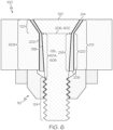
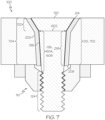
- Figs. 1 , 2A-B , 3 , 4A-C and 5-7 disclose examples of the fastener system 100.
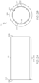
- Fig. 2A shows a side view of an example of a sleeve member 118 of the fastener system 100.
- Fig. 2B shows a distal end view of the sleeve member of Fig. 2A .
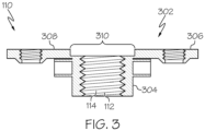
- Fig. 3 shows an example of a nut member 110 of the fastener system 100.
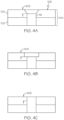
- Figs. 4A-C show examples of joining bores 116 in the workpiece 104 of Fig. 1 with a countersunk portion 402, a counterbored portion 404 and a cylindrical portion 406.
- a fastener system 100 for joining multiple substrates 102 of a workpiece 104 includes a nut member 110, a sleeve member 118 and a bolt member 120.
- the workpiece 104 has a working side 106 and a blind side 108.
- the nut member 110 includes a nut bore 112 with internal threads 114.
- the nut member 110 configured for placement of the nut bore 112 over a joining bore 116 through the multiple substrates 102 on the blind side 108 of the workpiece 104.
- the sleeve member 118 includes an outer sleeve surface 202 with a lubricious coating 204.
- the sleeve member 118 configured for insertion in the joining bore 116 through the multiple substrates 102 from the working side 106 of the workpiece 104.
- the bolt member 120 includes a head portion 122, a threaded portion 124 and a shank portion 126 extending between the head portion 122 and the threaded portion 124.
- the bolt member 120 configured for insertion in a central bore 206 of the sleeve member 118.
- the threaded portion 124 configured for threaded engagement with the internal threads 114 of the nut member 110.
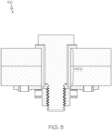
- the shank portion 126 of the bolt member 120 is configured to cause radial expansion of the sleeve member 118 and the sleeve member 118 is configured to provide an interference fit 502 within the joining bore 116 through the multiple substrates 102.
- the multiple substrates 102 include at least one composite material substrate 128.
- the nut member 110 is configured to be secured to the blind side 108 of the workpiece 104.
- the nut member 110 is configured to be secured to the blind side 108 of the workpiece 104 using mechanical fasteners, swagging or any other suitable fastening hardware/technique in any suitable combination.
- the nut member 110 includes a nut plate assembly 302 with a nut 304 and a flange plate 306 captively retaining the nut 304.
- the nut 304 includes the nut bore 112.
- the flange plate 306 configured to be secured to the blind side 108 of the workpiece 104 with the nut bore 112 over the joining bore 116 through the multiple substrates 102.
- the nut 304 captively retained by the flange plate 306 is spaced from a mounting surface 308 of the flange plate 306.
- the flange plate 306 includes a counterbore 310 into the mounting surface 308 in relative alignment with the nut bore 112 of the nut 304 and the joining bore 116 of the multiple substrates 102.
- the counterbore 310 configured to provide space for a distal end 208 of the sleeve member 118 protruding from the joining bore 116 at the blind side 108 of the workpiece 104 as the bolt member 120 becomes fully engaged with the nut member 110.
- the fastener system 100 also includes a cap sealant member 130 with a dome 132 and a cap flange 134.
- the cap sealant member 130 configured for placement over the nut member 110.
- the cap flange 134 configured to secure the cap sealant member 130 to the blind side 108 of the workpiece 104.
- the sleeve member 118 includes a malleable metallic material.
- the malleable metallic material includes tin, a tin alloy, copper, a copper alloy, aluminum, an aluminum alloy, silver, a silver alloy, gold, a gold alloy or any other suitable malleable metallic in any suitable combination.
- the lubricious coating 204 includes indium, an indium alloy, tin, a tin alloy, bismuth, a bismuth alloy, aluminum, an aluminum alloy or any other suitable lubricious coating in any suitable combination.
- the lubricious coating 204 on the outer sleeve surface 202 includes conductive features configured to provide electromagnetic energy protection to the workpiece 104 as the bolt member 120 becomes fully engaged with the nut member 110.
- the outer sleeve surface 202 is coated with a conductive coating 210 to provide electromagnetic energy protection to the workpiece 104 as the bolt member 120 becomes fully engaged with the nut member 110.
- the conductive coating 210 includes indium, an indium alloy, tin, a tin alloy, lead, a lead alloy or any other suitable conductive coating in any suitable combination.
- the sleeve member 118 also includes an elongated sleeve body 212 and a sleeve flange 216.
- the elongated sleeve body 212 defining the central bore 206.
- the elongated sleeve body 212 includes the outer sleeve surface 202, a proximal end 214 relating to the working side 106 of the workpiece 104 and a distal end 208 relating to the blind side 108 of the workpiece 104.
- the sleeve flange 216 disposed at the proximal end 214 of the elongated sleeve body 212.
- the sleeve flange 216 configured to limit further insertion of the sleeve member 118 into the joining bore 116 through the multiple substrates 102.
- the bolt member 120 includes a metallic material.
- the metallic material includes a stainless steel, titanium, a titanium alloy, a cobalt-chromium alloy, a nickel-titanium alloy or any other suitable metallic material in any suitable combination.
- the head portion 122 of the bolt member 120 includes a torquing feature 136.
- the torquing feature 136 is configured to facilitate rotation of the bolt member 120 using a hex key torquing tool, a cross-tip driver torquing tool, a flat tip driver torquing tool, a hex socket torquing tool or any other suitable torquing tool.
- the head portion 122 of the bolt member 120 includes a protruding head, a flush head, a countersunk head, a raised head, a recessed hexagon socket head, a recessed cross-tip head, a recessed flat tip head, a hexagon head or any other suitable type of head.
- the joining bore 116 through the multiple substrates 102 includes a countersunk portion 402, a counterbored portion 404, a cylindrical portion 406 or any other suitable geometry at the working side 106 compatible with the head portion 122 of the bolt member 120.
- the sleeve member 118 also includes an inner sleeve surface 218 and the shank portion 126 of the bolt member 120 includes an outer shank surface 138.
- at least one of the inner sleeve surface 218 and the outer shank surface 138 is coated with the lubricious coating 204.
- an outer shank diameter for the shank portion 126 of the bolt member 120 is substantially greater than an inner sleeve diameter for the sleeve member 118.
- the outer shank diameter is substantially greater than the inner sleeve diameter by approximately 0.0005 inches, approximately 0.0010 inches, approximately 0.0015 inches, approximately 0.0020 inches, approximately 0.0025 inches or any other suitable difference measurement resulting in substantial expansion of the sleeve member 118.
- the outer shank diameter is substantially greater than the inner sleeve diameter by approximately 0.2 percent, approximately 0.4 percent, approximately 0.6 percent, approximately 0.8 percent, approximately 1.0 percent or any other suitable percentage resulting in substantial expansion of the sleeve member 118.
- the sleeve member 118 also includes a cylindrical sleeve body 220 defining the central bore 206.
- the cylindrical sleeve body 220 includes the outer sleeve surface 202, an inner sleeve surface 218 facing the central bore 206, a proximal end 214 relating to the working side 106 of the workpiece 104 and a distal end 208 relating to the blind side 108 of the workpiece 104.
- the shank portion 126 of the bolt member 120 includes a cylindrical shank body 140.
- the cylindrical shank body 140 includes an outer shank surface 138 configured to face the inner sleeve surface 218 of the cylindrical sleeve body 220 as the bolt member 120 is inserted into the central bore 206 and becomes engaged with the nut member 110.
- an outer shank diameter for the cylindrical shank body 140 is substantially greater than an inner sleeve diameter for the cylindrical sleeve body 220.
- the outer shank diameter is substantially greater than the inner sleeve diameter by approximately 0.0005 inches, approximately 0.0010 inches, approximately 0.0015 inches, approximately 0.0020 inches, approximately 0.0025 inches or any other suitable difference measurement resulting in substantial expansion of the sleeve member 118.
- the outer shank diameter is substantially greater than the inner sleeve diameter by approximately 0.2 percent, approximately 0.4 percent, approximately 0.6 percent, approximately 0.8 percent, approximately 1.0 percent or any other suitable percentage resulting in substantial expansion of the sleeve member 118.
- the outer sleeve surface 202 is configured to provide the interference fit 502 within the joining bore 116 through the multiple substrates 102 in conjunction with a corresponding cylindrical shape of the joining bore 116.
- the sleeve member 118 also includes an elongated sleeve body 212 defining the central bore 206.
- the elongated sleeve body 212 includes the outer sleeve surface 202, an inner sleeve surface 218 facing the central bore 206, a proximal end 214 relating to the working side 106 of the workpiece 104 and a distal end 208 relating to the blind side 108 of the workpiece 104.
- At least the inner sleeve surface 218 is tapered from a larger inner sleeve diameter proximate the proximal end 214 to a smaller inner sleeve diameter proximate the distal end 208 such that the central bore 206 includes a frustoconical sleeve bore 602.
- the outer sleeve surface 202 is cylindrical such that the elongated sleeve body 212 includes a cylindrical sleeve body 220 with the frustoconical sleeve bore 602.
- the shank portion 126 of the bolt member 120 includes an elongated shank body 604 with an outer shank surface 138 configured to face the inner sleeve surface 218 as the bolt member 120 is inserted into the frustoconical sleeve bore 602 and becomes engaged with the nut member 110.
- the elongated shank body 604 is tapered from a larger outer shank diameter proximate the head portion 122 of the bolt member 120 to a smaller outer shank diameter proximate the threaded portion 124 of the bolt member 120 such that the elongated shank body 604 includes a frustoconical shank body 606.
- outer shank diameters for the frustoconical shank body 606 are substantially greater than corresponding inner sleeve diameters that define the frustoconical sleeve bore 602. In an even still further example, the outer shank diameters are substantially greater than the corresponding inner sleeve diameters by approximately 0.0005 inches, approximately 0.0010 inches, approximately 0.0015 inches, approximately 0.0020 inches, approximately 0.0025 inches or any other suitable difference measurement resulting in substantial expansion of the sleeve member 118.
- the outer shank diameters are substantially greater than the corresponding inner sleeve diameters by at least one of approximately 0.2 percent, approximately 0.4 percent, approximately 0.6 percent, approximately 0.8 percent, approximately 1.0 percent or any other suitable percentage resulting in substantial expansion of the sleeve member 118.
- the outer sleeve surface 202 is configured to provide the interference fit 608 within the joining bore 116 through the multiple substrates 102 in conjunction with a corresponding cylindrical shape of the joining bore 116.
- the outer sleeve surface 202 is tapered from a larger outer sleeve diameter proximate the proximal end 214 to a smaller outer sleeve diameter proximate the distal end 208 such that the elongated sleeve body 212 includes a frustoconical sleeve body 702.
- the shank portion 126 of the bolt member 120 includes an elongated shank body 604 with an outer shank surface 138 configured to face the inner sleeve surface 218 as the bolt member 120 is inserted into the frustoconical sleeve bore 602 and becomes engaged with the nut member 110.
- the elongated shank body 604 is tapered from a larger outer shank diameter proximate the head portion 122 of the bolt member 120 to a smaller outer shank diameter proximate the threaded portion 124 of the bolt member 120 such that the elongated shank body 604 includes a frustoconical shank body 606.
- outer shank diameters for the frustoconical shank body 606 are substantially greater than corresponding inner sleeve diameters that define the frustoconical sleeve bore 602. In an even still further example, the outer shank diameters are substantially greater than the corresponding inner sleeve diameters by approximately 0.0005 inches, approximately 0.0010 inches, approximately 0.0015 inches, approximately 0.0020 inches, approximately 0.0025 inches or any other suitable difference measurement resulting in substantial expansion of the sleeve member 118.
- the outer shank diameters are substantially greater than the corresponding inner sleeve diameters by approximately 0.2 percent, approximately 0.4 percent, approximately 0.6 percent, approximately 0.8 percent, approximately 1.0 percent or any other suitable percentage resulting in substantial expansion of the sleeve member 118.
- the frustoconical shank body 606 is configured to cause radial expansion of the frustoconical sleeve body 702 in conjunction with the frustoconical sleeve bore 602 of the frustoconical sleeve body 702 and the frustoconical sleeve body 702 is configured to provide the interference fit 704 within the joining bore 116 through the multiple substrates 102 in conjunction with a corresponding frustoconical shape of the joining bore 116.
- Figs. 1 , 2A-B , 3 and 5-17 by way of examples, the present disclosure is directed to methods 800, 1100, 1400 for joining multiple substrates 102 of a workpiece 104.
- the workpiece 104 has a working side 106 and a blind side 108.
- Figs. 1 and 5-7 disclose examples of the fastener system 100.
- Fig. 2A shows a side view of an example of a sleeve member 118 of the fastener system 100.
- Fig. 2B shows a distal end view of the sleeve member of Fig. 2A .
- Fig. 3 shows an example of a nut member 110 of the fastener system 100.
- Figs. 8-10 , 12 , 13 and 15-17 disclose various examples of the method 800.
- Figs. 8 and 11 disclose various examples of the method 1100.
- Figs. 8 and 14 disclose various examples of the method 1400.
- a method 800 for joining multiple substrates 102 of a workpiece 104 with a working side 106 and a blind side 108 includes securing 802 a nut member 110 over a joining bore 116 through the multiple substrates 102 on the blind side 108 of the workpiece 104.
- the nut member 110 includes a nut bore 112 with internal threads 114.
- a sleeve member 118 is inserted in the joining bore 116 through the multiple substrates 102 from the working side 106 of the workpiece 104.
- the sleeve member 118 includes an outer sleeve surface 202 with a lubricious coating 204.
- a bolt member 120 is inserted in a central bore 206 of the sleeve member 118 until a distal end of the bolt member 120 contacts the nut member 110.
- the bolt member 120 includes a head portion 122 at a proximal end, a threaded portion 124 at the distal end and a shank portion (126) extending between the head portion 122 and the threaded portion 124.
- the bolt member 120 is rotated to engage the threaded portion 124 with the internal threads 114 of the nut member 110.
- the sleeve member 118 is radially expanded within the joining bore 116 through the multiple substrates 102 as the bolt member 120 becomes fully engaged with the nut member 110.
- an interference fit 502 is provided for the sleeve member 118 within the joining bore 116 through the multiple substrates 102 in response to radial expansion of the sleeve member 118 as the bolt member 120 becomes fully engaged with the nut member 110.
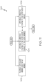
- the securing 802 the nut member 110 includes securing 902 (see Fig. 9 ) the nut member 110 to the blind side 108 of the workpiece 104 using mechanical fasteners, swagging or any other suitable fastening hardware/technique in any suitable combination.
- the nut member 110 also includes a nut plate assembly 302.
- the securing 802 the nut member 110 includes captively retaining 1002 (see Fig. 10 ) a nut 304 of the nut plate assembly 302 in a flange plate 306 of the nut plate assembly 302.
- the flange plate 306 is secured to the blind side 108 of the workpiece 104 with the nut bore 112 over the joining bore 116 through the multiple substrates 102.
- the securing 802 the nut member 110 also includes spacing 1006 the nut 304 of the nut plate assembly 302 from a mounting surface 308 of the flange plate 306.
- a counterbore 310 is provided in the mounting surface 308 of the flange plate 306 in relative alignment with the nut bore 112 of the nut 304 and the joining bore 116 of the multiple substrates 102.
- the counterbore 310 provides space for a distal end 208 of the sleeve member 118 protruding from the joining bore 116 at the blind side 108 of the workpiece 104 as the bolt member 120 becomes fully engaged with the nut member 110.
- a method 1100 for joining multiple substrates 102 of a workpiece 104 includes the method 800 of Fig. 8 and continues from 802 to 1102 where a cap sealant member 130 is placed over the nut member 110.
- the cap sealant member 130 includes a dome 132 and a cap flange 134.
- the cap flange 134 configured to secure the cap sealant member 130 to the blind side 108 of the workpiece 104.
- the method 1100 includes applying 1104 the lubricious coating 204 to the outer sleeve surface 202 of the sleeve member 118.
- the method 1100 continues from 1104 to 802 of Fig. 8 .
- the lubricious coating 204 on the outer sleeve surface 202 includes conductive features configured to provide electromagnetic energy protection to the workpiece 104 as the bolt member 120 becomes fully engaged with the nut member 110.
- the method 1100 includes applying 1106 a conductive coating 210 to the outer sleeve surface 202. In this example, the method 1100 continues from 1106 to 802 of Fig. 8 .
- the inserting 804 the sleeve member 118 includes limiting 1202 (see Fig. 12 ) further insertion of the sleeve member 118 into the joining bore 116 through the multiple substrates 102 based on a sleeve flange 216 at a proximal end 214 of an elongated sleeve body 212 of the sleeve member 118.
- the rotating 808 the bolt member 120 includes torquing 1302 (see Fig. 13 ) the bolt member 120 to become fully engaged with the nut member 110.
- a method 1400 for joining multiple substrates 102 of a workpiece 104 includes the method 800 of Fig. 8 and continues from 804 to 1402 where the lubricious coating 204 is applied to at least one of an inner sleeve surface 218 of the sleeve member 118 and an outer shank surface 138 of the shank portion 126 of the bolt member 120.
- an outer shank diameter for the shank portion (126) of the bolt member (120) is substantially greater than an inner sleeve diameter for the sleeve member (118).
- the sleeve member 118 also includes a cylindrical sleeve body 220 defining the central bore 206.
- the cylindrical sleeve body 220 includes the outer sleeve surface 202, an inner sleeve surface 218 facing the central bore 206, a proximal end 214 relating to the working side 106 of the workpiece 104 and a distal end 208 relating to the blind side 108 of the workpiece 104.
- the shank portion 126 of the bolt member 120 includes a cylindrical shank body 140.
- the cylindrical shank body 140 includes an outer shank surface 138 configured to face the inner sleeve surface 218 of the cylindrical sleeve body 220 as the bolt member 120 is inserted into the central bore 206 and becomes engaged with the nut member 110.
- an outer shank diameter for the cylindrical shank body 140 is substantially greater than an inner sleeve diameter for the cylindrical sleeve body 220.
- the providing 812 the interference fit 502 includes providing 1502 (see Fig. 15 ) the interference fit 502 within the joining bore 116 through the multiple substrates 102 in conjunction with a corresponding cylindrical shape of the joining bore 116 as the bolt member 120 becomes fully engaged with the nut member 110.
- the sleeve member 118 also includes an elongated sleeve body 212 defining the central bore 206.
- the elongated sleeve body 212 includes the outer sleeve surface 202, an inner sleeve surface 218 facing the central bore 206, a proximal end 214 relating to the working side 106 of the workpiece 104 and a distal end 208 relating to the blind side 108 of the workpiece 104.
- At least the inner sleeve surface 218 is tapered from a larger inner sleeve diameter proximate the proximal end 214 to a smaller inner sleeve diameter proximate the distal end 208 such that the central bore 206 includes a frustoconical sleeve bore 602.
- the outer sleeve surface 202 is cylindrical such that the elongated sleeve body 212 includes a cylindrical sleeve body 220 with the frustoconical sleeve bore 602.
- the shank portion 126 of the bolt member 120 includes an elongated shank body 604 with an outer shank surface 138 configured to face the inner sleeve surface 218 as the bolt member 120 is inserted into the frustoconical sleeve bore 602 and becomes engaged with the nut member 110.
- the elongated shank body 604 is tapered from a larger outer shank diameter proximate the head portion 122 of the bolt member 120 to a smaller outer shank diameter proximate the threaded portion 124 of the bolt member 120 such that the elongated shank body 604 includes a frustoconical shank body 606.
- outer shank diameters for the frustoconical shank body 606 are substantially greater than corresponding inner sleeve diameters that define the frustoconical sleeve bore 602.
- the providing 812 the interference fit 502 includes providing 1602 (see Fig. 16 ) the interference fit 608 within the joining bore 116 through the multiple substrates 102 in conjunction with a corresponding cylindrical shape of the joining bore 116 as the bolt member 120 becomes fully engaged with the nut member 110.
- the outer sleeve surface 202 is tapered from a larger outer sleeve diameter proximate the proximal end 214 to a smaller outer sleeve diameter proximate the distal end 208 such that the elongated sleeve body 212 includes a frustoconical sleeve body 702.
- the shank portion 126 of the bolt member 120 includes an elongated shank body 604 with an outer shank surface 138 configured to face the inner sleeve surface 218 as the bolt member 120 is inserted into the frustoconical sleeve bore 602 and becomes engaged with the nut member 110.
- the elongated shank body 604 is tapered from a larger outer shank diameter proximate the head portion 122 of the bolt member 120 to a smaller outer shank diameter proximate the threaded portion 124 of the bolt member 120 such that the elongated shank body 604 includes a frustoconical shank body 606.
- outer shank diameters for the frustoconical shank body 606 are substantially greater than corresponding inner sleeve diameters that define the frustoconical sleeve bore 602.
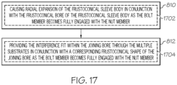
- the radially expanding 810 includes causing 1702 (see Fig.
- the providing 812 the interference fit 502 includes providing 1704 the interference fit 704 within the joining bore 116 through the multiple substrates 102 in conjunction with a corresponding frustoconical shape of the joining bore 116 as the bolt member 120 becomes fully engaged with the nut member 110.
- FIG. 3 shows an example of a nut member 110 of the fastener system 100.
- Figs. 4A-C show examples of joining bores 116 in the workpiece 104 of Fig. 1 with a countersunk portion 402, a counterbored portion 404 and a cylindrical portion 406.
- a fastener system 100 for joining multiple substrates 102 of a workpiece 104 includes a nut member 110 and a bolt member 120.
- the workpiece 104 has a working side 106 and a blind side 108.
- the nut member 110 includes a nut bore 112 with internal threads 114.
- the nut member 110 configured for placement over a joining bore 116 through the multiple substrates 102 on the blind side 108 of the workpiece 104.
- the joining bore 116 being tapered from a larger joining bore 116 diameter proximate the working side 106 of the workpiece 104 to a smaller joining bore 116 diameter proximate the blind side 108 of the workpiece 104 such that the joining bore 116 includes a frustoconical joining bore 1802.
- the bolt member 120 includes a head portion 122, a threaded portion 124 and a shank portion 126 extending between the head portion 122 and the threaded portion 124.
- the shank portion 126 includes an elongated shank body 604 with an outer shank surface 138.
- the elongated shank body 604 being tapered from a larger outer shank diameter proximate the head portion 122 to a smaller outer shank diameter proximate the threaded portion 124 such that the elongated shank body 604 includes a frustoconical shank body 606.
- the outer shank surface 138 coated with a lubricious coating 204.
- the bolt member 120 configured for insertion in the frustoconical joining bore 1802 through the multiple substrates 102 from the working side 106 of the workpiece 104 and configured for threaded engagement with the internal threads 114 of the nut member 110.
- the frustoconical shank body 606 is configured to provide an interference fit 1802 within the frustoconical joining bore 1802 through the multiple substrates 102 in conjunction with a corresponding frustoconical shape of the frustoconical joining bore 1802.
- the multiple substrates 102 include at least one composite material substrate 128.
- the nut member 110 is configured to be secured to the blind side 108 of the workpiece 104.
- the nut member 110 is configured to be secured to the blind side 108 of the workpiece 104 using mechanical fasteners, swagging or any other suitable fastening hardware/technique in any suitable combination.
- the nut member 110 also includes a nut plate assembly 302 with a nut 304 and a flange plate 306 captively retaining the nut 304.
- the nut 304 includes the nut bore 112.
- the flange plate 306 configured to be secured to the blind side 108 of the workpiece 104 with the nut bore 112 over the frustoconical joining bore 1802 through the multiple substrates 102.
- the fastener system 100 also includes a cap sealant member 130 with a dome 132 and a cap flange 134.
- the cap sealant member 130 configured for placement over the nut member 110.
- the cap flange 134 configured to secure the cap sealant member 130 to the blind side 108 of the workpiece 104.
- the lubricious coating 204 includes indium, an indium alloy, tin, a tin alloy, bismuth, a bismuth alloy, aluminum, an aluminum alloy or any other suitable lubricious coating in any suitable combination.
- the lubricious coating 204 on the outer shank surface 138 includes conductive features configured to provide electromagnetic energy protection to the workpiece 104 as the bolt member 120 becomes fully engaged with the nut member 110.
- the outer shank surface 138 is coated with a conductive coating 210 to provide electromagnetic energy protection to the workpiece 104 as the bolt member 120 becomes fully engaged with the nut member 110.
- the conductive coating 210 includes indium, an indium alloy, tin, a tin alloy, lead, a lead alloy or any other suitable conductive coating in any suitable combination.
- the bolt member 120 includes a metallic material.
- the metallic material includes a stainless steel, titanium, a titanium alloy, a cobalt-chromium alloy, a nickel-titanium alloy or any other suitable metallic material in any suitable combination.
- the head portion 122 of the bolt member 120 includes a torquing feature 136.
- the torquing feature 136 is configured to facilitate rotation of the bolt member 120 using a hex key torquing tool, a cross-tip driver torquing tool, a flat tip driver torquing tool, a hex socket torquing tool or any other suitable torquing tool.
- the head portion 122 of the bolt member 120 includes a protruding head, a flush head, a countersunk head, a raised head, a recessed hexagon socket head, a recessed cross-tip head, a recessed flat tip head, a hexagon head or any other suitable type of head.
- the frustoconical joining bore 1802 through the multiple substrates 102 includes a countersunk portion 402, a counterbored portion 404, a cylindrical portion 406 or any other suitable geometry at the working side 106 compatible with the head portion 122 of the bolt member 120.
- outer shank diameters for the frustoconical shank body 606 are substantially greater than corresponding frustoconical joining bore 1802 diameters that define the frustoconical joining bore 1802.
- the outer shank diameters are substantially greater than the corresponding frustoconical joining bore (1802) diameters by approximately 0.0005 inches, approximately 0.0010 inches, approximately 0.0015 inches, approximately 0.0020 inches, approximately 0.0025 inches or any other suitable difference measurement resulting the interference fit 1802 within the frustoconical joining bore 1802.
- the outer shank diameters are substantially greater than the corresponding frustoconical joining bore 1802 diameters by approximately 0.2 percent, approximately 0.4 percent, approximately 0.6 percent, approximately 0.8 percent, approximately 1.0 percent or any other suitable percentage resulting the interference fit 1802 within the frustoconical joining bore 1802.
- Figs. 1 , 2A-B , 3 , 4A-C and 18-23 by way of examples, the present disclosure is directed to methods 1900, 2200 for joining multiple substrates 102 of a workpiece 104.
- the workpiece 104 has a working side 106 and a blind side 108.
- Figs. 1 and 18 disclose examples of the fastener system 100.
- Fig. 2A shows a side view of an example of a sleeve member 118 of the fastener system 100.
- Fig. 2B shows a distal end view of the sleeve member of Fig. 2A .
- Fig. 3 shows an example of a nut member 110 of the fastener system 100.
- FIGS. 19-21 and 23 disclose various examples of the method 1900.
- Figs. 19 and 22 disclose various examples of the method 2200.
- a method 1900 for joining multiple substrates 102 of a workpiece 104 with a working side 106 and a blind side 108 includes securing 1902 a nut member 110 over a joining bore 116 through the multiple substrates 102 on the blind side 108 of the workpiece 104.
- the nut member 110 includes a nut bore 112 with internal threads 114.
- the joining bore 116 being tapered from a larger joining bore 116 diameter proximate the working side 106 of the workpiece 104 to a smaller joining bore 116 diameter proximate the blind side 108 of the workpiece 104 such that the joining bore 116 includes a frustoconical joining bore 1802.
- a bolt member 120 is inserted in the frustoconical joining bore 1802 through the multiple substrates 102 from the working side 106 of the workpiece 104 until a distal end of the bolt member 120 contacts the nut member 110.
- the bolt member 120 includes a head portion 122 at a proximal end, a threaded portion 124 at the distal end and a shank portion 126 extending between the head portion 122 and the threaded portion 124.
- the shank portion 126 being tapered from a larger outer shank diameter proximate the head portion 122 to a smaller outer shank diameter proximate the threaded portion 124 such that the shank portion 126 includes a frustoconical shank body 606.
- the shank portion 126 includes an outer shank surface 138 with a lubricious coating 204.
- the bolt member 120 is rotated to engage the threaded portion 124 with the internal threads 114 of the nut member 110.
- an interference fit 1802 is provided for the shank portion 126 of the bolt member 120 within the frustoconical joining bore 1802 through the multiple substrates 102 as the bolt member 120 becomes fully engaged with the nut member 110 in conjunction with a corresponding frustoconical shape of the frustoconical joining bore 1802.
- the securing 1902 the nut member 110 includes securing 2002 (see Fig. 20 ) the nut member 110 to the blind side 108 of the workpiece 104 using mechanical fasteners, swagging or any other suitable fastening hardware/technique in any suitable combination.
- the nut member 110 includes a nut plate assembly 302.
- the securing 1902 the nut member 110 includes captively retaining 2102 (see Fig. 21 ) a nut 304 of the nut plate assembly 302 in a flange plate 306 of the nut plate assembly 302.
- the flange plate 306 is secured to the blind side 108 of the workpiece 104 with the nut bore 112 over the frustoconical joining bore 1802 through the multiple substrates 102.
- a method 2200 for joining multiple substrates 102 of a workpiece 104 includes the method 1900 of Fig. 19 and continues from 1902 to 2202 where a cap sealant member 130 is placed over the nut member 110.
- the cap sealant member 130 including a dome 132 and a cap flange 134.
- the cap flange 134 configured to secure the cap sealant member 130 to the blind side 108 of the workpiece 104.
- the method 2200 continues from 1902 to 2204 where the lubricious coating 204 is applied to the outer shank surface 138 of the shank portion 126 of the bolt member 120.
- the lubricious coating 204 on the outer shank surface 138 includes conductive features configured to provide electromagnetic energy protection to the workpiece 104 as the bolt member 120 becomes fully engaged with the nut member 110.
- the method 2200 continues from 1902 to 2206 where a conductive coating 210 is applied to the outer shank surface 138 of the shank portion 126 of the bolt member 120.
- the rotating 1906 the bolt member 120 includes torquing 2302 the bolt member 120 to become fully engaged with the nut member 110.
- outer shank diameters for the frustoconical shank body 606 are substantially greater than corresponding frustoconical joining bore 1802 diameters that define the frustoconical joining bore 1802.
- Examples of fastener systems 100 and methods 800, 1100, 1400, 1900, 2200 for joining multiple substrates of a workpiece may be related to or used in the context of aircraft manufacturing.
- aircraft manufacturing an aircraft example is described, the examples and principles disclosed herein may be applied to other products in the aerospace industry and other industries, such as the automotive industry, the space industry, the construction industry and other design and manufacturing industries. Accordingly, in addition to aircraft, the examples and principles disclosed herein may apply to the use of composite products in the manufacture of various types of vehicles and in the construction of various types of buildings.
- example means that one or more feature, structure, element, component, characteristic and/or operational step described in connection with the example is included in at least one aspect, example and/or implementation of the subject matter according to the present disclosure.
- the phrases “an example,” “another example,” “one or more examples,” and similar language throughout the present disclosure may, but do not necessarily, refer to the same example.
- the subject matter characterizing any one example may, but does not necessarily, include the subject matter characterizing any other example.
- subject matter characterizing any one example may be, but is not necessarily, combined with the subject matter characterizing any other example.
- a system, apparatus, device, structure, article, element, component, or hardware “configured to” perform a specified function is indeed capable of performing the specified function without any alteration, rather than merely having potential to perform the specified function after further modification.
- the system, apparatus, device, structure, article, element, component, or hardware “configured to” perform a specified function is specifically selected, created, implemented, utilized, programmed and/or designed for the purpose of performing the specified function.
- "configured to” denotes existing characteristics of a system, apparatus, structure, article, element, component, or hardware that enable the system, apparatus, structure, article, element, component, or hardware to perform the specified function without further modification.
- a system, apparatus, device, structure, article, element, component, or hardware described as being “configured to” perform a particular function may additionally or alternatively be described as being “adapted to” and/or as being “operative to” perform that function.
- first,” “second,” “third,” etc. are used herein merely as labels and are not intended to impose ordinal, positional, or hierarchical requirements on the items to which these terms refer.
- reference to, e.g., a “second” item does not require or preclude the existence of, e.g., a "first” or lower-numbered item and/or, e.g., a "third” or higher-numbered item.
- the phrase "at least one of,” when used with a list of items, means different combinations of one or more of the listed items may be used and only one of each item in the list may be needed.
- “at least one of item A, item B and item C” may include, without limitation, item A or item A and item B. This example also may include item A, item B and item C or item B and item C.
- "at least one of' may be, for example, without limitation, two of item A, one of item B and ten of item C; four of item B and seven of item C; and other suitable combinations.
- the term “and/or” and the "j" symbol includes any and all combinations of one or more of the associated listed items.
- Coupled refers to two or more elements that are joined, linked, fastened, attached, connected, put in communication, or otherwise associated (e.g., mechanically, electrically, fluidly, optically, electromagnetically) with one another.
- the elements may be associated directly or indirectly.
- element A may be directly associated with element B.
- element A may be indirectly associated with element B, for example, via another element C. It will be understood that not all associations among the various disclosed elements are necessarily represented. Accordingly, couplings other than those depicted in the figures may also exist.
- the term “approximately” refers to or represents a condition that is close to, but not exactly, the stated condition that still performs the desired function or achieves the desired result.
- the term “approximately” refers to a condition that is within an acceptable predetermined tolerance or accuracy, such as to a condition that is within 10% of the stated condition.
- the term “approximately” does not exclude a condition that is exactly the stated condition.
- the term “substantially” refers to a condition that is essentially the stated condition that performs the desired function or achieves the desired result.
- Figs. 1 , 2A-B , 3 , 4A-C , 5-7 and 18 may represent functional elements, features, or components thereof and do not necessarily imply any particular structure. Accordingly, modifications, additions and/or omissions may be made to the illustrated structure. Additionally, those skilled in the art will appreciate that not all elements, features and/or components described and illustrated in Figs. 1 , 2A-B , 3 , 4A-C , 5-7 and 18 , referred to above, need be included in every example and not all elements, features and/or components described herein are necessarily depicted in each illustrative example. Accordingly, some of the elements, features and/or components described and illustrated in Figs.
- Figs. 8-17 and 19-23 referred to above, the blocks may represent operations, steps and/or portions thereof and lines connecting the various blocks do not imply any particular order or dependency of the operations or portions thereof. It will be understood that not all dependencies among the various disclosed operations are necessarily represented.
- Figs. 8-17 and 19-23 and the accompanying disclosure describing the operations of the disclosed methods set forth herein should not be interpreted as necessarily determining a sequence in which the operations are to be performed. Rather, although one illustrative order is indicated, it is to be understood that the sequence of the operations may be modified when appropriate. Accordingly, modifications, additions and/or omissions may be made to the operations illustrated and certain operations may be performed in a different order or simultaneously. Additionally, those skilled in the art will appreciate that not all operations described need be performed.
- references throughout the present specification to features, advantages, or similar language used herein do not imply that all the features and advantages that may be realized with the examples disclosed herein should be, or are in, any single example. Rather, language referring to the features and advantages is understood to mean that a specific feature, advantage, or characteristic described in connection with an example is included in at least one example. Thus, discussion of features, advantages and similar language used throughout the present disclosure may, but does not necessarily, refer to the same example.
- the disclosed methods and systems for associating test data for a part under test with an end item coordinate system may be used in aircraft manufacturing.
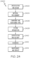
- the service method 2400 may include specification and design (block 2402) of aircraft 2500 and material procurement (block 2404).
- component and subassembly manufacturing (block 2406) and system integration (block 2408) of aircraft 2500 may take place.
- aircraft 2500 may go through certification and delivery (block 2410) to be placed in service (block 2412).
- aircraft 2500 may be scheduled for routine maintenance and service (block 2414). Routine maintenance and service may include modification, reconfiguration, refurbishment, etc. of one or more systems of aircraft 2500.
- Each of the processes of the service method 2400 may be performed or carried out by a system integrator, a third party and/or an operator (e.g., a customer).
- a system integrator may include, without limitation, any number of aircraft manufacturers and major-system subcontractors;
- a third party may include, without limitation, any number of vendors, subcontractors and suppliers;
- an operator may be an airline, leasing company, military entity, service organization and so on.
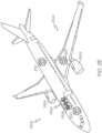
- aircraft 2500 produced by the service method 2400 may include airframe 2502 with a plurality of high-level systems 2504 and interior 2506.
- high-level systems 2504 include one or more of propulsion system 2508, electrical system 2510, hydraulic system 2512 and environmental system 2514. Any number of other systems may be included.
- propulsion system 2508 electrical system 2510
- hydraulic system 2512 hydraulic system 2512
- environmental system 2514 any number of other systems may be included.
- an aerospace example is shown, the principles disclosed herein may be applied to other industries, such as the automotive industry. Accordingly, in addition to aircraft 2500, the principles disclosed herein may apply to other vehicles, e.g., land vehicles, marine vehicles, space vehicles, etc.
- the disclosed systems and methods for associating test data for a part under test with an end item coordinate system may be employed during any one or more of the stages of the manufacturing and service method 2400.
- components or subassemblies corresponding to component and subassembly manufacturing (block 2406) may be fabricated or manufactured in a manner similar to components or subassemblies produced while aircraft 2500 is in service (block 2412).
- one or more examples of the system(s), method(s), or combination thereof may be utilized during production stages (block 2406 and block 2408), for example, by substantially expediting assembly of or reducing the cost of aircraft 2500.
- one or more examples of the system or method realizations, or a combination thereof may be utilized, for example and without limitation, while aircraft 2500 is in service (block 2412) and/or during maintenance and service (block 2414).
Landscapes
- Engineering & Computer Science (AREA)
- General Engineering & Computer Science (AREA)
- Mechanical Engineering (AREA)
- Manufacturing & Machinery (AREA)
- Transportation (AREA)
- Aviation & Aerospace Engineering (AREA)
- Connection Of Plates (AREA)
Abstract
Description
- The present disclosure relates generally to fastener systems for joining multiple substrates of a workpiece and, particularly, to fastener systems that provide an interference fit with a workpiece that includes one or more composite substrate. Conductive properties of the various fastener systems provide protection from electromagnetic effects. Various configurations of the fastener systems provide a pre-installed nut member on a blind side of the workpiece and a bolt member for one-sided installation from a working side.
- Current fastener systems require two-sided installation to obtain an interference fit between the fastener and the workpiece stack up. Conversely, existing fastener systems designed for one-sided installation only provide a clearance fit between the fastener and the stack up.
- Accordingly, those skilled in the art continue with research and development efforts to improve fastener systems for joining multiple substrates of a workpiece.
- Disclosed are examples of fastener systems and methods for joining multiple substrates of a workpiece. The following is a non-exhaustive list of examples, which may or may not be claimed, of the subject matter according to the present disclosure.
- In an example, a fastener system for joining multiple substrates of a workpiece is disclosed. The workpiece has a working side and a blind side. The fastener system includes a nut member, a sleeve member and a bolt member. The nut member includes a nut bore with internal threads. The nut member configured for placement of the nut bore over a joining bore through the multiple substrates on the blind side of the workpiece. The sleeve member includes an outer sleeve surface with a lubricious coating. The sleeve member configured for insertion in the joining bore through the multiple substrates from the working side of the workpiece. The bolt member includes a head portion, a threaded portion and a shank portion extending between the head portion and the threaded portion. The bolt member is configured for insertion in a central bore of the sleeve member. The threaded portion is configured for threaded engagement with the internal threads of the nut member. As the bolt member becomes fully engaged with the nut member, the shank portion of the bolt member is configured to cause radial expansion of the sleeve member and the sleeve member is configured to provide an interference fit within the joining bore through the multiple substrates.
- In an example, a method for joining multiple substrates of a workpiece is disclosed. The workpiece has a working side and a blind side. The method includes: (1) securing a nut member over a joining bore through the multiple substrates on the blind side of the workpiece, the nut member including a nut bore with internal threads; (2) inserting a sleeve member in the joining bore through the multiple substrates from the working side of the workpiece, the sleeve member including an outer sleeve surface with a lubricious coating; (3) inserting a bolt member in a central bore of the sleeve member until a distal end of the bolt member contacts the nut member, the bolt member including a head portion at a proximal end, a threaded portion at the distal end and a shank portion extending between the head portion and the threaded portion; (4) rotating the bolt member to engage the threaded portion with the internal threads of the nut member; (5) radially expanding the sleeve member within the joining bore through the multiple substrates as the bolt member becomes fully engaged with the nut member; and (6) providing an interference fit for the sleeve member within the joining bore through the multiple substrates in response to radial expansion of the sleeve member as the bolt member becomes fully engaged with the nut member.
- In an example, another fastener system for joining multiple substrates of a workpiece is disclosed. The workpiece has a working side and a blind side. The fastener system includes a nut member and a bolt member. The nut member includes a nut bore with internal threads. The nut member configured for placement over a joining bore through the multiple substrates on the blind side of the workpiece. The joining bore being tapered from a larger joining bore diameter proximate the working side of the workpiece to a smaller joining bore diameter proximate the blind side of the workpiece such that the joining bore includes a frustoconical joining bore. The bolt member includes a head portion, a threaded portion and a shank portion extending between the head portion and the threaded portion. The shank portion includes an elongated shank body with an outer shank surface. The elongated shank body being tapered from a larger outer shank diameter proximate the head portion to a smaller outer shank diameter proximate the threaded portion such that the elongated shank body includes a frustoconical shank body. The outer shank surface is coated with a lubricious coating. The bolt member configured for insertion in the frustoconical joining bore through the multiple substrates from the working side of the workpiece and configured for threaded engagement with the internal threads of the nut member. As the bolt member becomes fully engaged with the nut member, the frustoconical shank body is configured to provide an interference fit within the frustoconical joining bore through the multiple substrates in conjunction with a corresponding frustoconical shape of the frustoconical joining bore.
- In an example, another method for joining multiple substrates of a workpiece is disclosed. The workpiece has a working side and a blind side. The method includes: (1) securing a nut member over a joining bore through the multiple substrates on the blind side of the workpiece, the nut member includes a nut bore with internal threads, the joining bore being tapered from a larger joining bore diameter proximate the working side of the workpiece to a smaller joining bore diameter proximate the blind side of the workpiece such that the joining bore includes a frustoconical joining bore; (2) inserting a bolt member in the frustoconical joining bore through the multiple substrates from the working side of the workpiece until a distal end of the bolt member contacts the nut member, the bolt member includes a head portion at a proximal end, a threaded portion at the distal end and a shank portion extending between the head portion and the threaded portion, the shank portion being tapered from a larger outer shank diameter proximate the head portion to a smaller outer shank diameter proximate the threaded portion such that the shank portion includes a frustoconical shank body, the shank portion includes an outer shank surface with a lubricious coating; (3) rotating the bolt member to engage the threaded portion with the internal threads of the nut member; and (4) providing an interference fit for the shank portion of the bolt member within the frustoconical joining bore through the multiple substrates as the bolt member becomes fully engaged with the nut member in conjunction with a corresponding frustoconical shape of the frustoconical joining bore.
- Other examples of the disclosed fastener systems and methods for joining multiple substrates of a workpiece will become apparent from the following detailed description, the accompanying drawings and the appended claims.
-
-
Fig. 1 is a cross-sectional side view of an example of a partially installed fastener system for joining multiple substrates of a workpiece; -
Fig. 2A is a side view of an example of a sleeve member of the fastener system ofFig. 1 ; -
Fig. 2B is a distal end view of the sleeve member ofFig. 2A ; -
Fig. 3 is a cross-sectional side view of an example of a nut member of the fastener system ofFig. 1 ; -
Figs. 4A-C are cross-sectional side views of examples of countersunk, counterbored and cylindrical joining bores in workpieces having multiple substrates; -
Fig. 5 is a cross-sectional side view of the fastener system ofFig. 1 in which the fastener system is fully installed; -
Fig. 6 is a cross-sectional side view of another example of a fastener system for joining multiple substrates of a workpiece; -
Fig. 7 is a cross-sectional side view of yet another example of a fastener system for joining multiple substrates of a workpiece; -
Fig. 8 is a flow diagram of an example of a method for joining multiple substrates of a workpiece; -
Fig. 9 is a flow diagram showing a further example of "securing a nut member" from the method ofFig. 8 ; -
Fig. 10 is a flow diagram showing another further example of "securing a nut member" from the method ofFig. 8 ; -
Fig. 11 , in combination withFig. 8 , is a flow diagram of another example of a method for joining multiple substrates of a workpiece; -
Fig. 12 is a flow diagram showing a further example of "inserting a sleeve member" from the method ofFig. 8 ; -
Fig. 13 is a flow diagram showing a further example of "rotating the bolt member" from the method ofFig. 8 ; -
Fig. 14 , in combination withFig. 8 , is a flow diagram of yet another example of a method for joining multiple substrates of a workpiece; -
Fig. 15 is a flow diagram showing a further example of "providing an interference fit" from the method ofFig. 8 ; -
Fig. 16 is a flow diagram showing another further example of "providing an interference fit" from the method ofFig. 8 ; -
Fig. 17 is a flow diagram showing a further example of "radially expanding" from the method ofFig. 8 and yet another further example of "providing an interference fit" from the method ofFig. 8 ; -
Fig. 18 is a cross-sectional side view of still another example of a fastener system for joining multiple substrates of a workpiece; -
Fig. 19 is a flow diagram of still yet another example of a method for joining multiple substrates of a workpiece; -
Fig. 20 is a flow diagram showing a further example of "securing a nut member" from the method ofFig. 19 ; -
Fig. 21 is a flow diagram showing another further example of "securing a nut member" from the method ofFig. 19 ; -
Fig. 22 , in combination withFig. 19 , is a flow diagram of another example of a method for joining multiple substrates of a workpiece; -
Fig. 23 is a flow diagram showing a further example of "rotating the bolt member" from the method ofFig. 19 ; -
Fig. 24 is a block diagram of aircraft production and service methodology that implements one or more of the examples of methods for joining multiple substrates of a workpiece disclosed herein; and -
Fig. 25 is a schematic illustration of an aircraft that incorporates workpieces with multiple substrates that are joined using one or more of the examples of fastener systems and methods for joining multiple substrates of a workpiece disclosed herein. - The various examples of fastener systems and methods for joining multiple substrates of a workpiece disclosed herein provide techniques for pre-installing a nut member of the fastener system on a blind side of the workpiece and one-sided installation of other members of the fastener system from a working side of the workpiece. The workpiece, for example, may include one or more composite material substrates and may be used for aerospace construction.
- Referring generally to
Figs. 1 ,2A-B ,3 ,4A-C and5-7 , by way of examples, the present disclosure is directed to afastener system 100 for joiningmultiple substrates 102 of aworkpiece 104. Theworkpiece 104 has a workingside 106 and ablind side 108.Figs. 1 and5-7 disclose examples of thefastener system 100.Fig. 2A shows a side view of an example of asleeve member 118 of thefastener system 100.Fig. 2B shows a distal end view of the sleeve member ofFig. 2A .Fig. 3 shows an example of anut member 110 of thefastener system 100.Figs. 4A-C show examples of joiningbores 116 in theworkpiece 104 ofFig. 1 with a countersunkportion 402, a counterbored portion 404 and acylindrical portion 406. - With reference again to 1, 2A-B, 3, 4A-C and 5-7, in one or more examples, a
fastener system 100 for joiningmultiple substrates 102 of aworkpiece 104 includes anut member 110, asleeve member 118 and abolt member 120. Theworkpiece 104 has a workingside 106 and ablind side 108. Thenut member 110 includes anut bore 112 withinternal threads 114. Thenut member 110 configured for placement of the nut bore 112 over a joiningbore 116 through themultiple substrates 102 on theblind side 108 of theworkpiece 104. Thesleeve member 118 includes anouter sleeve surface 202 with alubricious coating 204. Thesleeve member 118 configured for insertion in the joiningbore 116 through themultiple substrates 102 from the workingside 106 of theworkpiece 104. Thebolt member 120 includes ahead portion 122, a threadedportion 124 and ashank portion 126 extending between thehead portion 122 and the threadedportion 124. Thebolt member 120 configured for insertion in acentral bore 206 of thesleeve member 118. The threadedportion 124 configured for threaded engagement with theinternal threads 114 of thenut member 110. As thebolt member 120 becomes fully engaged with thenut member 110, theshank portion 126 of thebolt member 120 is configured to cause radial expansion of thesleeve member 118 and thesleeve member 118 is configured to provide aninterference fit 502 within the joiningbore 116 through themultiple substrates 102. - In another example of the
fastener system 100, themultiple substrates 102 include at least onecomposite material substrate 128. In yet another example of thefastener system 100, thenut member 110 is configured to be secured to theblind side 108 of theworkpiece 104. In a further example, thenut member 110 is configured to be secured to theblind side 108 of theworkpiece 104 using mechanical fasteners, swagging or any other suitable fastening hardware/technique in any suitable combination. - In still another example of the
fastener system 100, thenut member 110 includes anut plate assembly 302 with anut 304 and aflange plate 306 captively retaining thenut 304. Thenut 304 includes the nut bore 112. Theflange plate 306 configured to be secured to theblind side 108 of theworkpiece 104 with the nut bore 112 over the joiningbore 116 through themultiple substrates 102. In a further example, thenut 304 captively retained by theflange plate 306 is spaced from a mountingsurface 308 of theflange plate 306. In this example, theflange plate 306 includes acounterbore 310 into the mountingsurface 308 in relative alignment with the nut bore 112 of thenut 304 and the joiningbore 116 of themultiple substrates 102. Thecounterbore 310 configured to provide space for adistal end 208 of thesleeve member 118 protruding from the joiningbore 116 at theblind side 108 of theworkpiece 104 as thebolt member 120 becomes fully engaged with thenut member 110. - In still yet another example, the
fastener system 100 also includes acap sealant member 130 with adome 132 and acap flange 134. Thecap sealant member 130 configured for placement over thenut member 110. Thecap flange 134 configured to secure thecap sealant member 130 to theblind side 108 of theworkpiece 104. - In another example of the
fastener system 100, thesleeve member 118 includes a malleable metallic material. In a further example, the malleable metallic material includes tin, a tin alloy, copper, a copper alloy, aluminum, an aluminum alloy, silver, a silver alloy, gold, a gold alloy or any other suitable malleable metallic in any suitable combination. - In yet another example of the
fastener system 100, thelubricious coating 204 includes indium, an indium alloy, tin, a tin alloy, bismuth, a bismuth alloy, aluminum, an aluminum alloy or any other suitable lubricious coating in any suitable combination. In still another example of thefastener system 100, thelubricious coating 204 on theouter sleeve surface 202 includes conductive features configured to provide electromagnetic energy protection to theworkpiece 104 as thebolt member 120 becomes fully engaged with thenut member 110. In still yet another example of thefastener system 100, theouter sleeve surface 202 is coated with aconductive coating 210 to provide electromagnetic energy protection to theworkpiece 104 as thebolt member 120 becomes fully engaged with thenut member 110. In a further example, theconductive coating 210 includes indium, an indium alloy, tin, a tin alloy, lead, a lead alloy or any other suitable conductive coating in any suitable combination. - In another example of the
fastener system 100, thesleeve member 118 also includes anelongated sleeve body 212 and asleeve flange 216. Theelongated sleeve body 212 defining thecentral bore 206. Theelongated sleeve body 212 includes theouter sleeve surface 202, aproximal end 214 relating to the workingside 106 of theworkpiece 104 and adistal end 208 relating to theblind side 108 of theworkpiece 104. Thesleeve flange 216 disposed at theproximal end 214 of theelongated sleeve body 212. Thesleeve flange 216 configured to limit further insertion of thesleeve member 118 into the joiningbore 116 through themultiple substrates 102. - In yet another example of the
fastener system 100, thebolt member 120 includes a metallic material. In a further example, the metallic material includes a stainless steel, titanium, a titanium alloy, a cobalt-chromium alloy, a nickel-titanium alloy or any other suitable metallic material in any suitable combination. In still another example of thefastener system 100, thehead portion 122 of thebolt member 120 includes atorquing feature 136. In a further example, the torquingfeature 136 is configured to facilitate rotation of thebolt member 120 using a hex key torquing tool, a cross-tip driver torquing tool, a flat tip driver torquing tool, a hex socket torquing tool or any other suitable torquing tool. In still yet another example of thefastener system 100, thehead portion 122 of thebolt member 120 includes a protruding head, a flush head, a countersunk head, a raised head, a recessed hexagon socket head, a recessed cross-tip head, a recessed flat tip head, a hexagon head or any other suitable type of head. In another example of thefastener system 100, at the workingside 106 of theworkpiece 104, the joiningbore 116 through themultiple substrates 102 includes a countersunkportion 402, a counterbored portion 404, acylindrical portion 406 or any other suitable geometry at the workingside 106 compatible with thehead portion 122 of thebolt member 120. - In yet another example of the
fastener system 100, thesleeve member 118 also includes aninner sleeve surface 218 and theshank portion 126 of thebolt member 120 includes anouter shank surface 138. In this example, at least one of theinner sleeve surface 218 and theouter shank surface 138 is coated with thelubricious coating 204. - In still another example of the
fastener system 100, an outer shank diameter for theshank portion 126 of thebolt member 120 is substantially greater than an inner sleeve diameter for thesleeve member 118. In a further example, the outer shank diameter is substantially greater than the inner sleeve diameter by approximately 0.0005 inches, approximately 0.0010 inches, approximately 0.0015 inches, approximately 0.0020 inches, approximately 0.0025 inches or any other suitable difference measurement resulting in substantial expansion of thesleeve member 118. In another further example, the outer shank diameter is substantially greater than the inner sleeve diameter by approximately 0.2 percent, approximately 0.4 percent, approximately 0.6 percent, approximately 0.8 percent, approximately 1.0 percent or any other suitable percentage resulting in substantial expansion of thesleeve member 118. - In still yet another example of the
fastener system 100, thesleeve member 118 also includes acylindrical sleeve body 220 defining thecentral bore 206. Thecylindrical sleeve body 220 includes theouter sleeve surface 202, aninner sleeve surface 218 facing thecentral bore 206, aproximal end 214 relating to the workingside 106 of theworkpiece 104 and adistal end 208 relating to theblind side 108 of theworkpiece 104. In a further example, theshank portion 126 of thebolt member 120 includes acylindrical shank body 140. Thecylindrical shank body 140 includes anouter shank surface 138 configured to face theinner sleeve surface 218 of thecylindrical sleeve body 220 as thebolt member 120 is inserted into thecentral bore 206 and becomes engaged with thenut member 110. - In an even further example, an outer shank diameter for the
cylindrical shank body 140 is substantially greater than an inner sleeve diameter for thecylindrical sleeve body 220. In an even yet further example, the outer shank diameter is substantially greater than the inner sleeve diameter by approximately 0.0005 inches, approximately 0.0010 inches, approximately 0.0015 inches, approximately 0.0020 inches, approximately 0.0025 inches or any other suitable difference measurement resulting in substantial expansion of thesleeve member 118. In another even further example, the outer shank diameter is substantially greater than the inner sleeve diameter by approximately 0.2 percent, approximately 0.4 percent, approximately 0.6 percent, approximately 0.8 percent, approximately 1.0 percent or any other suitable percentage resulting in substantial expansion of thesleeve member 118. - In another even further example, as the
bolt member 120 becomes fully engaged with thenut member 110, theouter sleeve surface 202 is configured to provide theinterference fit 502 within the joiningbore 116 through themultiple substrates 102 in conjunction with a corresponding cylindrical shape of the joiningbore 116. - In another example of the
fastener system 100, thesleeve member 118 also includes anelongated sleeve body 212 defining thecentral bore 206. Theelongated sleeve body 212 includes theouter sleeve surface 202, aninner sleeve surface 218 facing thecentral bore 206, aproximal end 214 relating to the workingside 106 of theworkpiece 104 and adistal end 208 relating to theblind side 108 of theworkpiece 104. In this example, at least theinner sleeve surface 218 is tapered from a larger inner sleeve diameter proximate theproximal end 214 to a smaller inner sleeve diameter proximate thedistal end 208 such that thecentral bore 206 includes a frustoconical sleeve bore 602. - In a further example, the
outer sleeve surface 202 is cylindrical such that theelongated sleeve body 212 includes acylindrical sleeve body 220 with the frustoconical sleeve bore 602. In an even further example, theshank portion 126 of thebolt member 120 includes anelongated shank body 604 with anouter shank surface 138 configured to face theinner sleeve surface 218 as thebolt member 120 is inserted into the frustoconical sleeve bore 602 and becomes engaged with thenut member 110. In this example, theelongated shank body 604 is tapered from a larger outer shank diameter proximate thehead portion 122 of thebolt member 120 to a smaller outer shank diameter proximate the threadedportion 124 of thebolt member 120 such that theelongated shank body 604 includes afrustoconical shank body 606. - In an even yet further example, outer shank diameters for the
frustoconical shank body 606 are substantially greater than corresponding inner sleeve diameters that define the frustoconical sleeve bore 602. In an even still further example, the outer shank diameters are substantially greater than the corresponding inner sleeve diameters by approximately 0.0005 inches, approximately 0.0010 inches, approximately 0.0015 inches, approximately 0.0020 inches, approximately 0.0025 inches or any other suitable difference measurement resulting in substantial expansion of thesleeve member 118. In another even still further example, the outer shank diameters are substantially greater than the corresponding inner sleeve diameters by at least one of approximately 0.2 percent, approximately 0.4 percent, approximately 0.6 percent, approximately 0.8 percent, approximately 1.0 percent or any other suitable percentage resulting in substantial expansion of thesleeve member 118. - In another even yet further example, as the
bolt member 120 becomes fully engaged with thenut member 110, theouter sleeve surface 202 is configured to provide theinterference fit 608 within the joiningbore 116 through themultiple substrates 102 in conjunction with a corresponding cylindrical shape of the joiningbore 116. - In another further example, the
outer sleeve surface 202 is tapered from a larger outer sleeve diameter proximate theproximal end 214 to a smaller outer sleeve diameter proximate thedistal end 208 such that theelongated sleeve body 212 includes a frustoconical sleeve body 702. In an even further example, theshank portion 126 of thebolt member 120 includes anelongated shank body 604 with anouter shank surface 138 configured to face theinner sleeve surface 218 as thebolt member 120 is inserted into the frustoconical sleeve bore 602 and becomes engaged with thenut member 110. In this example, theelongated shank body 604 is tapered from a larger outer shank diameter proximate thehead portion 122 of thebolt member 120 to a smaller outer shank diameter proximate the threadedportion 124 of thebolt member 120 such that theelongated shank body 604 includes afrustoconical shank body 606. - In an even yet further example, outer shank diameters for the
frustoconical shank body 606 are substantially greater than corresponding inner sleeve diameters that define the frustoconical sleeve bore 602. In an even still further example, the outer shank diameters are substantially greater than the corresponding inner sleeve diameters by approximately 0.0005 inches, approximately 0.0010 inches, approximately 0.0015 inches, approximately 0.0020 inches, approximately 0.0025 inches or any other suitable difference measurement resulting in substantial expansion of thesleeve member 118. In another even still further example, the outer shank diameters are substantially greater than the corresponding inner sleeve diameters by approximately 0.2 percent, approximately 0.4 percent, approximately 0.6 percent, approximately 0.8 percent, approximately 1.0 percent or any other suitable percentage resulting in substantial expansion of thesleeve member 118. - In another even yet further example, as the
bolt member 120 becomes fully engaged with thenut member 110, thefrustoconical shank body 606 is configured to cause radial expansion of the frustoconical sleeve body 702 in conjunction with the frustoconical sleeve bore 602 of the frustoconical sleeve body 702 and the frustoconical sleeve body 702 is configured to provide theinterference fit 704 within the joiningbore 116 through themultiple substrates 102 in conjunction with a corresponding frustoconical shape of the joiningbore 116. - Referring generally to
Figs. 1 ,2A-B ,3 and5-17 , by way of examples, the present disclosure is directed tomethods multiple substrates 102 of aworkpiece 104. Theworkpiece 104 has a workingside 106 and ablind side 108.Figs. 1 and5-7 disclose examples of thefastener system 100.Fig. 2A shows a side view of an example of asleeve member 118 of thefastener system 100.Fig. 2B shows a distal end view of the sleeve member ofFig. 2A .Fig. 3 shows an example of anut member 110 of thefastener system 100.Figs. 8-10 ,12 ,13 and15-17 disclose various examples of themethod 800.Figs. 8 and11 disclose various examples of themethod 1100.Figs. 8 and14 disclose various examples of themethod 1400. - With reference again to
Figs. 1 ,2A-B ,3 ,5-10 ,12, 13 and15-17 , in one or more examples, a method 800 (seeFig. 8 ) for joiningmultiple substrates 102 of aworkpiece 104 with a workingside 106 and ablind side 108 includes securing 802 anut member 110 over a joiningbore 116 through themultiple substrates 102 on theblind side 108 of theworkpiece 104. Thenut member 110 includes anut bore 112 withinternal threads 114. At 804, asleeve member 118 is inserted in the joiningbore 116 through themultiple substrates 102 from the workingside 106 of theworkpiece 104. Thesleeve member 118 includes anouter sleeve surface 202 with alubricious coating 204. At 806, abolt member 120 is inserted in acentral bore 206 of thesleeve member 118 until a distal end of thebolt member 120 contacts thenut member 110. Thebolt member 120 includes ahead portion 122 at a proximal end, a threadedportion 124 at the distal end and a shank portion (126) extending between thehead portion 122 and the threadedportion 124. At 808, thebolt member 120 is rotated to engage the threadedportion 124 with theinternal threads 114 of thenut member 110. At 810, thesleeve member 118 is radially expanded within the joiningbore 116 through themultiple substrates 102 as thebolt member 120 becomes fully engaged with thenut member 110. At 812, aninterference fit 502 is provided for thesleeve member 118 within the joiningbore 116 through themultiple substrates 102 in response to radial expansion of thesleeve member 118 as thebolt member 120 becomes fully engaged with thenut member 110. - In another example of the
method 800, the securing 802 thenut member 110 includes securing 902 (seeFig. 9 ) thenut member 110 to theblind side 108 of theworkpiece 104 using mechanical fasteners, swagging or any other suitable fastening hardware/technique in any suitable combination. - In yet another example of the
method 800, thenut member 110 also includes anut plate assembly 302. In this example, the securing 802 thenut member 110 includes captively retaining 1002 (seeFig. 10 ) anut 304 of thenut plate assembly 302 in aflange plate 306 of thenut plate assembly 302. At 1004, theflange plate 306 is secured to theblind side 108 of theworkpiece 104 with the nut bore 112 over the joiningbore 116 through themultiple substrates 102. In a further example, the securing 802 thenut member 110 also includes spacing 1006 thenut 304 of thenut plate assembly 302 from a mountingsurface 308 of theflange plate 306. At 1008, acounterbore 310 is provided in the mountingsurface 308 of theflange plate 306 in relative alignment with the nut bore 112 of thenut 304 and the joiningbore 116 of themultiple substrates 102. In this example, thecounterbore 310 provides space for adistal end 208 of thesleeve member 118 protruding from the joiningbore 116 at theblind side 108 of theworkpiece 104 as thebolt member 120 becomes fully engaged with thenut member 110. - With reference again to
Figs. 1 ,2A-B ,8 and11 , in one or more examples, a method 1100 (seeFig. 11 ) for joiningmultiple substrates 102 of aworkpiece 104 includes themethod 800 ofFig. 8 and continues from 802 to 1102 where acap sealant member 130 is placed over thenut member 110. Thecap sealant member 130 includes adome 132 and acap flange 134. Thecap flange 134 configured to secure thecap sealant member 130 to theblind side 108 of theworkpiece 104. In another example, themethod 1100 includes applying 1104 thelubricious coating 204 to theouter sleeve surface 202 of thesleeve member 118. In this example, themethod 1100 continues from 1104 to 802 ofFig. 8 . In a further example of themethod 1100, thelubricious coating 204 on theouter sleeve surface 202 includes conductive features configured to provide electromagnetic energy protection to theworkpiece 104 as thebolt member 120 becomes fully engaged with thenut member 110. In yet another example, themethod 1100 includes applying 1106 aconductive coating 210 to theouter sleeve surface 202. In this example, themethod 1100 continues from 1106 to 802 ofFig. 8 . - With reference again to
Figs. 1 ,2A-B ,3 ,5-10 ,12, 13 and15-17 , in still another example of themethod 800, the inserting 804 thesleeve member 118 includes limiting 1202 (seeFig. 12 ) further insertion of thesleeve member 118 into the joiningbore 116 through themultiple substrates 102 based on asleeve flange 216 at aproximal end 214 of anelongated sleeve body 212 of thesleeve member 118. In still yet another example of themethod 800, the rotating 808 thebolt member 120 includes torquing 1302 (seeFig. 13 ) thebolt member 120 to become fully engaged with thenut member 110. - With reference again to
Figs. 1 ,2A-B ,8 and14 , in one or more examples, a method 1400 (seeFig. 14 ) for joiningmultiple substrates 102 of aworkpiece 104 includes themethod 800 ofFig. 8 and continues from 804 to 1402 where thelubricious coating 204 is applied to at least one of aninner sleeve surface 218 of thesleeve member 118 and anouter shank surface 138 of theshank portion 126 of thebolt member 120. - With reference again to
Figs. 1 ,2A-B ,3 ,5-10 ,12, 13 and15-17 , in another example of themethod 800, an outer shank diameter for the shank portion (126) of the bolt member (120) is substantially greater than an inner sleeve diameter for the sleeve member (118). - In yet another example of the
method 800, thesleeve member 118 also includes acylindrical sleeve body 220 defining thecentral bore 206. Thecylindrical sleeve body 220 includes theouter sleeve surface 202, aninner sleeve surface 218 facing thecentral bore 206, aproximal end 214 relating to the workingside 106 of theworkpiece 104 and adistal end 208 relating to theblind side 108 of theworkpiece 104. In a further example, theshank portion 126 of thebolt member 120 includes acylindrical shank body 140. Thecylindrical shank body 140 includes anouter shank surface 138 configured to face theinner sleeve surface 218 of thecylindrical sleeve body 220 as thebolt member 120 is inserted into thecentral bore 206 and becomes engaged with thenut member 110. In an even further example, an outer shank diameter for thecylindrical shank body 140 is substantially greater than an inner sleeve diameter for thecylindrical sleeve body 220. In another even further example of themethod 800, the providing 812 theinterference fit 502 includes providing 1502 (seeFig. 15 ) theinterference fit 502 within the joiningbore 116 through themultiple substrates 102 in conjunction with a corresponding cylindrical shape of the joiningbore 116 as thebolt member 120 becomes fully engaged with thenut member 110. - In still another example of the
method 800, thesleeve member 118 also includes anelongated sleeve body 212 defining thecentral bore 206. Theelongated sleeve body 212 includes theouter sleeve surface 202, aninner sleeve surface 218 facing thecentral bore 206, aproximal end 214 relating to the workingside 106 of theworkpiece 104 and adistal end 208 relating to theblind side 108 of theworkpiece 104. In this example, at least theinner sleeve surface 218 is tapered from a larger inner sleeve diameter proximate theproximal end 214 to a smaller inner sleeve diameter proximate thedistal end 208 such that thecentral bore 206 includes a frustoconical sleeve bore 602. - In a further example, the
outer sleeve surface 202 is cylindrical such that theelongated sleeve body 212 includes acylindrical sleeve body 220 with the frustoconical sleeve bore 602. In an even further example, theshank portion 126 of thebolt member 120 includes anelongated shank body 604 with anouter shank surface 138 configured to face theinner sleeve surface 218 as thebolt member 120 is inserted into the frustoconical sleeve bore 602 and becomes engaged with thenut member 110. In this example, theelongated shank body 604 is tapered from a larger outer shank diameter proximate thehead portion 122 of thebolt member 120 to a smaller outer shank diameter proximate the threadedportion 124 of thebolt member 120 such that theelongated shank body 604 includes afrustoconical shank body 606. In an even yet further example, outer shank diameters for thefrustoconical shank body 606 are substantially greater than corresponding inner sleeve diameters that define the frustoconical sleeve bore 602. In another even yet further example of themethod 800, the providing 812 theinterference fit 502 includes providing 1602 (seeFig. 16 ) theinterference fit 608 within the joiningbore 116 through themultiple substrates 102 in conjunction with a corresponding cylindrical shape of the joiningbore 116 as thebolt member 120 becomes fully engaged with thenut member 110. - In another further example, the
outer sleeve surface 202 is tapered from a larger outer sleeve diameter proximate theproximal end 214 to a smaller outer sleeve diameter proximate thedistal end 208 such that theelongated sleeve body 212 includes a frustoconical sleeve body 702. In an even further example, theshank portion 126 of thebolt member 120 includes anelongated shank body 604 with anouter shank surface 138 configured to face theinner sleeve surface 218 as thebolt member 120 is inserted into the frustoconical sleeve bore 602 and becomes engaged with thenut member 110. In this example, theelongated shank body 604 is tapered from a larger outer shank diameter proximate thehead portion 122 of thebolt member 120 to a smaller outer shank diameter proximate the threadedportion 124 of thebolt member 120 such that theelongated shank body 604 includes afrustoconical shank body 606. In an even yet further example, outer shank diameters for thefrustoconical shank body 606 are substantially greater than corresponding inner sleeve diameters that define the frustoconical sleeve bore 602. In another even yet further example of themethod 800, the radially expanding 810 includes causing 1702 (seeFig. 17 ) radial expansion of the frustoconical sleeve body 702 in conjunction with the frustoconical sleeve bore 602 of the frustoconical sleeve body 702 as thebolt member 120 becomes fully engaged with thenut member 110. In this example, the providing 812 theinterference fit 502 includes providing 1704 theinterference fit 704 within the joiningbore 116 through themultiple substrates 102 in conjunction with a corresponding frustoconical shape of the joiningbore 116 as thebolt member 120 becomes fully engaged with thenut member 110. - Referring generally to
Figs. 1 ,2A-B ,3 ,4A-C and18 , by way of examples, the present disclosure is directed to afastener system 100 for joiningmultiple substrates 102 of aworkpiece 104. Theworkpiece 104 has a workingside 106 and ablind side 108.Figs. 1 ,5-7 and18 disclose examples of thefastener system 100.Figs. 1 and18 disclose examples of thefastener system 100.Fig. 2A shows a side view of an example of asleeve member 118 of thefastener system 100.Fig. 2B shows a distal end view of the sleeve member ofFig. 2A .Fig. 3 shows an example of anut member 110 of thefastener system 100.Figs. 4A-C show examples of joiningbores 116 in theworkpiece 104 ofFig. 1 with a countersunkportion 402, a counterbored portion 404 and acylindrical portion 406. - With reference again to
Figs. 1 ,2A-B ,3 ,4A-C and18 , in one or more examples, afastener system 100 for joiningmultiple substrates 102 of aworkpiece 104 includes anut member 110 and abolt member 120. Theworkpiece 104 has a workingside 106 and ablind side 108. Thenut member 110 includes anut bore 112 withinternal threads 114. Thenut member 110 configured for placement over a joiningbore 116 through themultiple substrates 102 on theblind side 108 of theworkpiece 104. The joiningbore 116 being tapered from a larger joiningbore 116 diameter proximate the workingside 106 of theworkpiece 104 to a smaller joiningbore 116 diameter proximate theblind side 108 of theworkpiece 104 such that the joiningbore 116 includes a frustoconical joining bore 1802. Thebolt member 120 includes ahead portion 122, a threadedportion 124 and ashank portion 126 extending between thehead portion 122 and the threadedportion 124. Theshank portion 126 includes anelongated shank body 604 with anouter shank surface 138. Theelongated shank body 604 being tapered from a larger outer shank diameter proximate thehead portion 122 to a smaller outer shank diameter proximate the threadedportion 124 such that theelongated shank body 604 includes afrustoconical shank body 606. Theouter shank surface 138 coated with alubricious coating 204. Thebolt member 120 configured for insertion in the frustoconical joining bore 1802 through themultiple substrates 102 from the workingside 106 of theworkpiece 104 and configured for threaded engagement with theinternal threads 114 of thenut member 110. As thebolt member 120 becomes fully engaged with thenut member 110, thefrustoconical shank body 606 is configured to provide an interference fit 1802 within the frustoconical joining bore 1802 through themultiple substrates 102 in conjunction with a corresponding frustoconical shape of the frustoconical joining bore 1802. - In another example of the
fastener system 100, themultiple substrates 102 include at least onecomposite material substrate 128. In yet another example of thefastener system 100, thenut member 110 is configured to be secured to theblind side 108 of theworkpiece 104. In a further example, thenut member 110 is configured to be secured to theblind side 108 of theworkpiece 104 using mechanical fasteners, swagging or any other suitable fastening hardware/technique in any suitable combination. In still another example of thefastener system 100, thenut member 110 also includes anut plate assembly 302 with anut 304 and aflange plate 306 captively retaining thenut 304. Thenut 304 includes the nut bore 112. Theflange plate 306 configured to be secured to theblind side 108 of theworkpiece 104 with the nut bore 112 over the frustoconical joining bore 1802 through themultiple substrates 102. - In still yet another example, the
fastener system 100 also includes acap sealant member 130 with adome 132 and acap flange 134. Thecap sealant member 130 configured for placement over thenut member 110. Thecap flange 134 configured to secure thecap sealant member 130 to theblind side 108 of theworkpiece 104. In another example of thefastener system 100, thelubricious coating 204 includes indium, an indium alloy, tin, a tin alloy, bismuth, a bismuth alloy, aluminum, an aluminum alloy or any other suitable lubricious coating in any suitable combination. In yet another example of thefastener system 100, thelubricious coating 204 on theouter shank surface 138 includes conductive features configured to provide electromagnetic energy protection to theworkpiece 104 as thebolt member 120 becomes fully engaged with thenut member 110. In still another example of thefastener system 100, theouter shank surface 138 is coated with aconductive coating 210 to provide electromagnetic energy protection to theworkpiece 104 as thebolt member 120 becomes fully engaged with thenut member 110. In a further example, theconductive coating 210 includes indium, an indium alloy, tin, a tin alloy, lead, a lead alloy or any other suitable conductive coating in any suitable combination. - In still yet another example of the
fastener system 100, thebolt member 120 includes a metallic material. In a further example, the metallic material includes a stainless steel, titanium, a titanium alloy, a cobalt-chromium alloy, a nickel-titanium alloy or any other suitable metallic material in any suitable combination. In another example of thefastener system 100, thehead portion 122 of thebolt member 120 includes atorquing feature 136. In a further example, the torquingfeature 136 is configured to facilitate rotation of thebolt member 120 using a hex key torquing tool, a cross-tip driver torquing tool, a flat tip driver torquing tool, a hex socket torquing tool or any other suitable torquing tool. In yet another example of thefastener system 100, thehead portion 122 of thebolt member 120 includes a protruding head, a flush head, a countersunk head, a raised head, a recessed hexagon socket head, a recessed cross-tip head, a recessed flat tip head, a hexagon head or any other suitable type of head. - In still another example of the
fastener system 100, at the workingside 106 of theworkpiece 104, the frustoconical joining bore 1802 through themultiple substrates 102 includes a countersunkportion 402, a counterbored portion 404, acylindrical portion 406 or any other suitable geometry at the workingside 106 compatible with thehead portion 122 of thebolt member 120. In still yet another example of thefastener system 100, outer shank diameters for thefrustoconical shank body 606 are substantially greater than corresponding frustoconical joining bore 1802 diameters that define the frustoconical joining bore 1802. In a further example, the outer shank diameters are substantially greater than the corresponding frustoconical joining bore (1802) diameters by approximately 0.0005 inches, approximately 0.0010 inches, approximately 0.0015 inches, approximately 0.0020 inches, approximately 0.0025 inches or any other suitable difference measurement resulting the interference fit 1802 within the frustoconical joining bore 1802. In another example of thefastener system 100, the outer shank diameters are substantially greater than the corresponding frustoconical joining bore 1802 diameters by approximately 0.2 percent, approximately 0.4 percent, approximately 0.6 percent, approximately 0.8 percent, approximately 1.0 percent or any other suitable percentage resulting the interference fit 1802 within the frustoconical joining bore 1802. - Referring generally to
Figs. 1 ,2A-B ,3 ,4A-C and18-23 , by way of examples, the present disclosure is directed tomethods multiple substrates 102 of aworkpiece 104. Theworkpiece 104 has a workingside 106 and ablind side 108.Figs. 1 and18 disclose examples of thefastener system 100.Fig. 2A shows a side view of an example of asleeve member 118 of thefastener system 100.Fig. 2B shows a distal end view of the sleeve member ofFig. 2A .Fig. 3 shows an example of anut member 110 of thefastener system 100.Figs. 4A-C show examples of joiningbores 116 in theworkpiece 104 ofFig. 1 with a countersunkportion 402, a counterbored portion 404 and acylindrical portion 406.Figs. 19-21 and23 disclose various examples of themethod 1900.Figs. 19 and22 disclose various examples of themethod 2200. - With reference again to
Figs. 1 ,2A-B ,3 ,4A-C ,18-21 and23 , in one or more examples, a method 1900 (seeFig. 19 ) for joiningmultiple substrates 102 of aworkpiece 104 with a workingside 106 and ablind side 108 includes securing 1902 anut member 110 over a joiningbore 116 through themultiple substrates 102 on theblind side 108 of theworkpiece 104. Thenut member 110 includes anut bore 112 withinternal threads 114. The joiningbore 116 being tapered from a larger joiningbore 116 diameter proximate the workingside 106 of theworkpiece 104 to a smaller joiningbore 116 diameter proximate theblind side 108 of theworkpiece 104 such that the joiningbore 116 includes a frustoconical joining bore 1802. At 1904, abolt member 120 is inserted in the frustoconical joining bore 1802 through themultiple substrates 102 from the workingside 106 of theworkpiece 104 until a distal end of thebolt member 120 contacts thenut member 110. Thebolt member 120 includes ahead portion 122 at a proximal end, a threadedportion 124 at the distal end and ashank portion 126 extending between thehead portion 122 and the threadedportion 124. Theshank portion 126 being tapered from a larger outer shank diameter proximate thehead portion 122 to a smaller outer shank diameter proximate the threadedportion 124 such that theshank portion 126 includes afrustoconical shank body 606. Theshank portion 126 includes anouter shank surface 138 with alubricious coating 204. At 1906, thebolt member 120 is rotated to engage the threadedportion 124 with theinternal threads 114 of thenut member 110. At 1908, an interference fit 1802 is provided for theshank portion 126 of thebolt member 120 within the frustoconical joining bore 1802 through themultiple substrates 102 as thebolt member 120 becomes fully engaged with thenut member 110 in conjunction with a corresponding frustoconical shape of the frustoconical joining bore 1802. - In another example of the
method 1900, the securing 1902 thenut member 110 includes securing 2002 (seeFig. 20 ) thenut member 110 to theblind side 108 of theworkpiece 104 using mechanical fasteners, swagging or any other suitable fastening hardware/technique in any suitable combination. - In yet another example of the
method 1900, thenut member 110 includes anut plate assembly 302. In this example, the securing 1902 thenut member 110 includes captively retaining 2102 (seeFig. 21 ) anut 304 of thenut plate assembly 302 in aflange plate 306 of thenut plate assembly 302. At 2104, theflange plate 306 is secured to theblind side 108 of theworkpiece 104 with the nut bore 112 over the frustoconical joining bore 1802 through themultiple substrates 102. - With reference again to
Figs. 1 ,2A-B ,19 and22 , in one or more examples, a method 2200 (seeFig. 22 ) for joiningmultiple substrates 102 of aworkpiece 104 includes themethod 1900 ofFig. 19 and continues from 1902 to 2202 where acap sealant member 130 is placed over thenut member 110. Thecap sealant member 130 including adome 132 and acap flange 134. Thecap flange 134 configured to secure thecap sealant member 130 to theblind side 108 of theworkpiece 104. In another example, themethod 2200 continues from 1902 to 2204 where thelubricious coating 204 is applied to theouter shank surface 138 of theshank portion 126 of thebolt member 120. In yet another example of themethod 2200, thelubricious coating 204 on theouter shank surface 138 includes conductive features configured to provide electromagnetic energy protection to theworkpiece 104 as thebolt member 120 becomes fully engaged with thenut member 110. In still another example, themethod 2200 continues from 1902 to 2206 where aconductive coating 210 is applied to theouter shank surface 138 of theshank portion 126 of thebolt member 120. - With reference again to
Figs. 1 ,18-21 and23 , in another example of themethod 1900, the rotating 1906 thebolt member 120 includes torquing 2302 thebolt member 120 to become fully engaged with thenut member 110. In yet another example of themethod 1900 outer shank diameters for thefrustoconical shank body 606 are substantially greater than corresponding frustoconical joining bore 1802 diameters that define the frustoconical joining bore 1802. - Examples of
fastener systems 100 andmethods - The preceding detailed description refers to the accompanying drawings, which illustrate specific examples described by the present disclosure. Other examples having different structures and operations do not depart from the scope of the present disclosure. Like reference numerals may refer to the same feature, element, or component in the different drawings. Throughout the present disclosure, any one of a plurality of items may be referred to individually as the item and a plurality of items may be referred to collectively as the items and may be referred to with like reference numerals. Moreover, as used herein, a feature, element, component, or step preceded with the word "a" or "an" should be understood as not excluding a plurality of features, elements, components, or steps, unless such exclusion is explicitly recited.
- Illustrative, non-exhaustive examples, which may be, but are not necessarily, claimed, of the subject matter according to the present disclosure are provided above. Reference herein to "example" means that one or more feature, structure, element, component, characteristic and/or operational step described in connection with the example is included in at least one aspect, example and/or implementation of the subject matter according to the present disclosure. Thus, the phrases "an example," "another example," "one or more examples," and similar language throughout the present disclosure may, but do not necessarily, refer to the same example. Further, the subject matter characterizing any one example may, but does not necessarily, include the subject matter characterizing any other example. Moreover, the subject matter characterizing any one example may be, but is not necessarily, combined with the subject matter characterizing any other example.
- As used herein, a system, apparatus, device, structure, article, element, component, or hardware "configured to" perform a specified function is indeed capable of performing the specified function without any alteration, rather than merely having potential to perform the specified function after further modification. In other words, the system, apparatus, device, structure, article, element, component, or hardware "configured to" perform a specified function is specifically selected, created, implemented, utilized, programmed and/or designed for the purpose of performing the specified function. As used herein, "configured to" denotes existing characteristics of a system, apparatus, structure, article, element, component, or hardware that enable the system, apparatus, structure, article, element, component, or hardware to perform the specified function without further modification. For purposes of this disclosure, a system, apparatus, device, structure, article, element, component, or hardware described as being "configured to" perform a particular function may additionally or alternatively be described as being "adapted to" and/or as being "operative to" perform that function.
- Unless otherwise indicated, the terms "first," "second," "third," etc., are used herein merely as labels and are not intended to impose ordinal, positional, or hierarchical requirements on the items to which these terms refer. Moreover, reference to, e.g., a "second" item does not require or preclude the existence of, e.g., a "first" or lower-numbered item and/or, e.g., a "third" or higher-numbered item.
- As used herein, the phrase "at least one of," when used with a list of items, means different combinations of one or more of the listed items may be used and only one of each item in the list may be needed. For example, "at least one of item A, item B and item C" may include, without limitation, item A or item A and item B. This example also may include item A, item B and item C or item B and item C. In other examples, "at least one of' may be, for example, without limitation, two of item A, one of item B and ten of item C; four of item B and seven of item C; and other suitable combinations. As used herein, the term "and/or" and the "j" symbol includes any and all combinations of one or more of the associated listed items.
- As used herein, the terms "coupled," "coupling," and similar terms refer to two or more elements that are joined, linked, fastened, attached, connected, put in communication, or otherwise associated (e.g., mechanically, electrically, fluidly, optically, electromagnetically) with one another. In various examples, the elements may be associated directly or indirectly. As an example, element A may be directly associated with element B. As another example, element A may be indirectly associated with element B, for example, via another element C. It will be understood that not all associations among the various disclosed elements are necessarily represented. Accordingly, couplings other than those depicted in the figures may also exist.
- As used herein, the term "approximately" refers to or represents a condition that is close to, but not exactly, the stated condition that still performs the desired function or achieves the desired result. As an example, the term "approximately" refers to a condition that is within an acceptable predetermined tolerance or accuracy, such as to a condition that is within 10% of the stated condition. However, the term "approximately" does not exclude a condition that is exactly the stated condition. As used herein, the term "substantially" refers to a condition that is essentially the stated condition that performs the desired function or achieves the desired result.
- In
Figs. 1 ,2A-B ,3 ,4A-C ,5-7 and18 , referred to above, may represent functional elements, features, or components thereof and do not necessarily imply any particular structure. Accordingly, modifications, additions and/or omissions may be made to the illustrated structure. Additionally, those skilled in the art will appreciate that not all elements, features and/or components described and illustrated inFigs. 1 ,2A-B ,3 ,4A-C ,5-7 and18 , referred to above, need be included in every example and not all elements, features and/or components described herein are necessarily depicted in each illustrative example. Accordingly, some of the elements, features and/or components described and illustrated inFigs. 1 ,2A-B ,3 ,4A-C ,5-7 and18 may be combined in various ways without the need to include other features described and illustrated inFigs. 1 ,2A-B ,3 ,4A-C ,5-7 and18 , other drawing figures and/or the accompanying disclosure, even though such combination or combinations are not explicitly illustrated herein. Similarly, additional features not limited to the examples presented, may be combined with some or all the features shown and described herein. Unless otherwise explicitly stated, the schematic illustrations of the examples depicted inFigs. 1 ,2A-B ,3 ,4A-C ,5-7 and18 , referred to above, are not meant to imply structural limitations with respect to the illustrative example. Rather, although one illustrative structure is indicated, it is to be understood that the structure may be modified when appropriate. Accordingly, modifications, additions and/or omissions may be made to the illustrated structure. Furthermore, elements, features and/or components that serve a similar, or at least substantially similar, purpose are labeled with like numbers in each ofFigs. 1 ,2A-B ,3 ,4A-C ,5-7 and18 and such elements, features and/or components may not be discussed in detail herein with reference to each ofFigs. 1 ,2A-B ,3 ,4A-C ,5-7 and18 . Similarly, all elements, features and/or components may not be labeled in each ofFigs. 1 ,2A-B ,3 ,4A-C ,5-7 and18 , but reference numerals associated therewith may be utilized herein for consistency. - In
Figs. 8-17 and19-23 , referred to above, the blocks may represent operations, steps and/or portions thereof and lines connecting the various blocks do not imply any particular order or dependency of the operations or portions thereof. It will be understood that not all dependencies among the various disclosed operations are necessarily represented.Figs. 8-17 and 19-23 and the accompanying disclosure describing the operations of the disclosed methods set forth herein should not be interpreted as necessarily determining a sequence in which the operations are to be performed. Rather, although one illustrative order is indicated, it is to be understood that the sequence of the operations may be modified when appropriate. Accordingly, modifications, additions and/or omissions may be made to the operations illustrated and certain operations may be performed in a different order or simultaneously. Additionally, those skilled in the art will appreciate that not all operations described need be performed. - Further, references throughout the present specification to features, advantages, or similar language used herein do not imply that all the features and advantages that may be realized with the examples disclosed herein should be, or are in, any single example. Rather, language referring to the features and advantages is understood to mean that a specific feature, advantage, or characteristic described in connection with an example is included in at least one example. Thus, discussion of features, advantages and similar language used throughout the present disclosure may, but does not necessarily, refer to the same example.
- Examples of the subject matter disclosed herein may be described in the context of aircraft manufacturing and
service method 2400 as shown inFig. 24 andaircraft 2500 as shown inFig. 25 . In one or more examples, the disclosed methods and systems for associating test data for a part under test with an end item coordinate system may be used in aircraft manufacturing. During pre-production, theservice method 2400 may include specification and design (block 2402) ofaircraft 2500 and material procurement (block 2404). During production, component and subassembly manufacturing (block 2406) and system integration (block 2408) ofaircraft 2500 may take place. Thereafter,aircraft 2500 may go through certification and delivery (block 2410) to be placed in service (block 2412). While in service,aircraft 2500 may be scheduled for routine maintenance and service (block 2414). Routine maintenance and service may include modification, reconfiguration, refurbishment, etc. of one or more systems ofaircraft 2500. - Each of the processes of the
service method 2400 may be performed or carried out by a system integrator, a third party and/or an operator (e.g., a customer). For the purposes of this description, a system integrator may include, without limitation, any number of aircraft manufacturers and major-system subcontractors; a third party may include, without limitation, any number of vendors, subcontractors and suppliers; and an operator may be an airline, leasing company, military entity, service organization and so on. - As shown in
Fig. 25 ,aircraft 2500 produced by theservice method 2400 may includeairframe 2502 with a plurality of high-level systems 2504 and interior 2506. Examples of high-level systems 2504 include one or more ofpropulsion system 2508,electrical system 2510,hydraulic system 2512 andenvironmental system 2514. Any number of other systems may be included. Although an aerospace example is shown, the principles disclosed herein may be applied to other industries, such as the automotive industry. Accordingly, in addition toaircraft 2500, the principles disclosed herein may apply to other vehicles, e.g., land vehicles, marine vehicles, space vehicles, etc. - The disclosed systems and methods for associating test data for a part under test with an end item coordinate system may be employed during any one or more of the stages of the manufacturing and
service method 2400. For example, components or subassemblies corresponding to component and subassembly manufacturing (block 2406) may be fabricated or manufactured in a manner similar to components or subassemblies produced whileaircraft 2500 is in service (block 2412). Also, one or more examples of the system(s), method(s), or combination thereof may be utilized during production stages (block 2406 and block 2408), for example, by substantially expediting assembly of or reducing the cost ofaircraft 2500. Similarly, one or more examples of the system or method realizations, or a combination thereof, may be utilized, for example and without limitation, whileaircraft 2500 is in service (block 2412) and/or during maintenance and service (block 2414). - Further examples are set out in the clauses below:
- 1. A fastener system for joining multiple substrates of a workpiece, the workpiece having a working side and a blind side, the fastener system comprising:
- a nut member comprising a nut bore with internal threads, the nut member configured for placement of the nut bore over a joining bore through the multiple substrates on the blind side of the workpiece;
- a sleeve member comprising an outer sleeve surface with a lubricious coating, the sleeve member configured for insertion in the joining bore through the multiple substrates from the working side of the workpiece; and
- a bolt member comprising a head portion, a threaded portion and a shank portion extending between the head portion and the threaded portion, the bolt member configured for insertion in a central bore of the sleeve member, the threaded portion configured for threaded engagement with the internal threads of the nut member,
- wherein, as the bolt member becomes fully engaged with the nut member, the shank portion of the bolt member is configured to cause radial expansion of the sleeve member and the sleeve member is configured to provide an interference fit within the joining bore through the multiple substrates.
- 2. The fastener system of Clause 1 wherein the multiple substrates comprise at least one composite material substrate.
- 3. The fastener system as claimed in any one of the preceding Clauses wherein the nut member is configured to be secured to the blind side of the workpiece.
- 4. The fastener system of Clause 3 wherein the nut member is configured to be secured to the blind side of the workpiece using at least one of mechanical fasteners and swagging.
- 5. The fastener system as claimed in any one of the preceding Clauses, the nut member further comprising:
a nut plate assembly comprising a nut and a flange plate captively retaining the nut, the nut comprising the nut bore, the flange plate configured to be secured to the blind side of the workpiece with the nut bore over the joining bore through the multiple substrates. - 6. The fastener system of Clause 5 wherein the nut captively retained by the flange plate is spaced from a mounting surface of the flange plate, the flange plate comprising:
a counterbore into the mounting surface in relative alignment with the nut bore of the nut and the joining bore of the multiple substrates, the counterbore configured to provide space for a distal end of the sleeve member protruding from the joining bore at the blind side of the workpiece as the bolt member becomes fully engaged with the nut member. - 7. The fastener system as claimed in any one of the preceding Clauses, further comprising:
a cap sealant member comprising a dome and a cap flange, the cap sealant member configured for placement over the nut member, the cap flange configured to secure the cap sealant member to the blind side of the workpiece. - 8. The fastener system of as claimed in any one of the preceding Clauses wherein the sleeve member comprises a malleable metallic material.
- 9. The fastener system of as claimed in any one of the preceding Clauses wherein the malleable metallic material comprises at least one of tin, a tin alloy, copper, a copper alloy, aluminum, an aluminum alloy, silver, a silver alloy, gold and a gold alloy.
- 10. The fastener system of as claimed in any one of the preceding Clauses wherein the lubricious coating comprises at least one of indium, an indium alloy, tin, a tin alloy, bismuth, a bismuth alloy, aluminum and an aluminum alloy.
- 11. The fastener system as claimed in any one of the preceding Clauses wherein the lubricious coating on the outer sleeve surface comprises conductive features configured to provide electromagnetic energy protection to the workpiece as the bolt member becomes fully engaged with the nut member.
- 12. The fastener system as claimed in any one of the preceding Clauses wherein the outer sleeve surface is coated with a conductive coating to provide electromagnetic energy protection to the workpiece as the bolt member becomes fully engaged with the nut member.
- 13. The fastener system of Clause 12 wherein the conductive coating comprises at least one of indium, an indium alloy, tin, a tin alloy, lead and a lead alloy.
- 14. The fastener system as claimed in any one of the preceding Clauses, the sleeve member further comprising:
- an elongated sleeve body defining the central bore, the elongated sleeve body comprising the outer sleeve surface, a proximal end relating to the working side of the workpiece and a distal end relating to the blind side of the workpiece; and
- a sleeve flange disposed at the proximal end of the elongated sleeve body, the sleeve flange configured to limit further insertion of the sleeve member into the joining bore through the multiple substrates.
- 15. The fastener system as claimed in any one of the preceding Clauses wherein the bolt member comprises a metallic material.
- 16. The fastener system of Clause 15 wherein the metallic material comprises at least one of a stainless steel, titanium, a titanium alloy, a cobalt-chromium alloy and a nickel-titanium alloy.
- 17. The fastener system as claimed in any one of the preceding Clauses, the head portion of the bolt member comprises a torquing feature.
- 18. The fastener system of Clause 17 wherein the torquing feature is configured to facilitate rotation of the bolt member using at least one of a hex key torquing tool, a cross-tip driver torquing tool, a flat tip driver torquing tool and a hex socket torquing tool.
- 19. The fastener system as claimed in any one of the preceding Clauses wherein the head portion of the bolt member comprises at least one of a protruding head, a flush head, a countersunk head, a raised head, a recessed hexagon socket head, a recessed cross-tip head, a recessed flat tip head and a hexagon head.
- 20. The fastener system as claimed in any one of the preceding Clauses wherein, at the working side of the workpiece, the joining bore through the multiple substrates comprises at least one of a countersunk portion, a counterbored portion and a cylindrical portion.
- 21. The fastener system as claimed in any one of the preceding Clauses, the sleeve member further comprising an inner sleeve surface and the shank portion of the bolt member comprising an outer shank surface, wherein at least one of the inner sleeve surface and the outer shank surface is coated with the lubricious coating.
- 22. The fastener system as claimed in any one of the preceding Clauses wherein an outer shank diameter for the shank portion of the bolt member is substantially greater than an inner sleeve diameter for the sleeve member.
- 23. The fastener system of Clause 22 wherein the outer shank diameter is substantially greater than the inner sleeve diameter by at least one of approximately 0.0005 inches, approximately 0.0010 inches, approximately 0.0015 inches, approximately 0.0020 inches and approximately 0.0025 inches.
- 24. The fastener system of Clause 22 wherein the outer shank diameter is substantially greater than the inner sleeve diameter by at least one of approximately 0.2 percent, approximately 0.4 percent, approximately 0.6 percent, approximately 0.8 percent and approximately 1.0 percent.
- 25. The fastener system as claimed in any one of the preceding Clauses, the sleeve member further comprising:
a cylindrical sleeve body defining the central bore, the cylindrical sleeve body comprising the outer sleeve surface, an inner sleeve surface facing the central bore, a proximal end relating to the working side of the workpiece and a distal end relating to the blind side of the workpiece. - 26. The fastener system as claimed in any one of the preceding Clauses, the shank portion of the bolt member comprising:
a cylindrical shank body comprising an outer shank surface configured to face the inner sleeve surface of the cylindrical sleeve body as the bolt member is inserted into the central bore and becomes engaged with the nut member. - 27. The fastener system as claimed in any one of the preceding Clauses wherein an outer shank diameter for the cylindrical shank body is substantially greater than an inner sleeve diameter for the cylindrical sleeve body.
- 28. The fastener system of Clause 27 wherein the outer shank diameter is substantially greater than the inner sleeve diameter by at least one of approximately 0.0005 inches, approximately 0.0010 inches, approximately 0.0015 inches, approximately 0.0020 inches and approximately 0.0025 inches.
- 29. The fastener system of Clause 27 wherein the outer shank diameter is substantially greater than the inner sleeve diameter by at least one of approximately 0.2 percent, approximately 0.4 percent, approximately 0.6 percent, approximately 0.8 percent and approximately 1.0 percent.
- 30. The fastener system of Clause 26 wherein, as the bolt member becomes fully engaged with the nut member, the outer sleeve surface is configured to provide the interference fit within the joining bore through the multiple substrates in conjunction with a corresponding cylindrical shape of the joining bore.
- 31. The fastener system as claimed in any one of the preceding Clauses, the sleeve member further comprising:
- an elongated sleeve body defining the central bore, the elongated sleeve body comprising the outer sleeve surface, an inner sleeve surface facing the central bore, a proximal end relating to the working side of the workpiece and a distal end relating to the blind side of the workpiece,
- wherein at least the inner sleeve surface is tapered from a larger inner sleeve diameter proximate the proximal end to a smaller inner sleeve diameter proximate the distal end such that the central bore comprises a frustoconical sleeve bore.
- 32. The fastener system of Clause 31 wherein the outer sleeve surface is cylindrical such that the elongated sleeve body comprises a cylindrical sleeve body with the frustoconical sleeve bore.
- 33. The fastener system of Clause 32, the shank portion of the bolt member comprising:
- an elongated shank body with an outer shank surface configured to face the inner sleeve surface as the bolt member is inserted into the frustoconical sleeve bore and becomes engaged with the nut member,
- wherein the elongated shank body is tapered from a larger outer shank diameter proximate the head portion of the bolt member to a smaller outer shank diameter proximate the threaded portion of the bolt member such that the elongated shank body comprises a frustoconical shank body.
- 34. The fastener system of Clause 33 wherein outer shank diameters for the frustoconical shank body are substantially greater than corresponding inner sleeve diameters that define the frustoconical sleeve bore.
- 35. The fastener system of Clause 34 wherein the outer shank diameters are substantially greater than the corresponding inner sleeve diameters by at least one of approximately 0.0005 inches, approximately 0.0010 inches, approximately 0.0015 inches, approximately 0.0020 inches and approximately 0.0025 inches.
- 36. The fastener system of Clause 34 wherein the outer shank diameters are substantially greater than the corresponding inner sleeve diameters by at least one of approximately 0.2 percent, approximately 0.4 percent, approximately 0.6 percent, approximately 0.8 percent and approximately 1.0 percent.
- 37. The fastener system of any one of Clause 33-35 wherein, as the bolt member becomes fully engaged with the nut member, the outer sleeve surface is configured to provide the interference fit within the joining bore through the multiple substrates in conjunction with a corresponding cylindrical shape of the joining bore.
- 38. The fastener system of any one of Clauses 31-37 wherein the outer sleeve surface is tapered from a larger outer sleeve diameter proximate the proximal end to a smaller outer sleeve diameter proximate the distal end such that the elongated sleeve body comprises a frustoconical sleeve body.
- 39. The fastener system of Clause 38, the shank portion of the bolt member comprising:
- an elongated shank body with an outer shank surface configured to face the inner sleeve surface as the bolt member is inserted into the frustoconical sleeve bore and becomes engaged with the nut member,
- wherein the elongated shank body is tapered from a larger outer shank diameter proximate the head portion of the bolt member to a smaller outer shank diameter proximate the threaded portion of the bolt member such that the elongated shank body comprises a frustoconical shank body.
- 40. The fastener system of Clause 39 wherein outer shank diameters for the frustoconical shank body are substantially greater than corresponding inner sleeve diameters that define the frustoconical sleeve bore.
- 41. The fastener system of Clause 40 wherein the outer shank diameters are substantially greater than the corresponding inner sleeve diameters by at least one of approximately 0.0005 inches, approximately 0.0010 inches, approximately 0.0015 inches, approximately 0.0020 inches and approximately 0.0025 inches.
- 42. The fastener system of Clause 40 wherein the outer shank diameters are substantially greater than the corresponding inner sleeve diameters by at least one of approximately 0.2 percent, approximately 0.4 percent, approximately 0.6 percent, approximately 0.8 percent and approximately 1.0 percent.
- 43. The fastener system of any one of Clauses 39-42 wherein, as the bolt member becomes fully engaged with the nut member, the frustoconical shank body is configured to cause radial expansion of the frustoconical sleeve body in conjunction with the frustoconical sleeve bore of the frustoconical sleeve body and the frustoconical sleeve body is configured to provide the interference fit within the joining bore through the multiple substrates in conjunction with a corresponding frustoconical shape of the joining bore.
- 44. A method for joining multiple substrates of a workpiece, the workpiece having a working side and a blind side, the method comprising:
- securing a nut member over a joining bore through the multiple substrates on the blind side of the workpiece, the nut member comprising a nut bore with internal threads;
- inserting a sleeve member in the joining bore through the multiple substrates from the working side of the workpiece, the sleeve member comprising an outer sleeve surface with a lubricious coating;
- inserting a bolt member in a central bore of the sleeve member until a distal end of the bolt member contacts the nut member, the bolt member comprising a head portion at a proximal end, a threaded portion at the distal end and a shank portion extending between the head portion and the threaded portion;
- rotating the bolt member to engage the threaded portion with the internal threads of the nut member;
- radially expanding the sleeve member within the joining bore through the multiple substrates as the bolt member becomes fully engaged with the nut member; and
- providing an interference fit for the sleeve member within the joining bore through the multiple substrates in response to radial expansion of the sleeve member as the bolt member becomes fully engaged with the nut member .
- 45. The method of Clause 44, the securing the nut member comprising:
securing the nut member to the blind side of the workpiece using at least one of mechanical fasteners and swagging. - 46. The method of Clause 44 or 45, wherein the nut member further comprises a nut plate assembly, the securing the nut member comprising:
- captively retaining a nut of the nut plate assembly in a flange plate of the nut plate assembly; and
- securing the flange plate to the blind side of the workpiece with the nut bore over the joining bore through the multiple substrates.
- 47. The method of Clause 46, the securing the nut member further comprising:
- spacing the nut of the nut plate assembly from a mounting surface of the flange plate; and
- providing a counterbore in the mounting surface of the flange plate in relative alignment with the nut bore of the nut and the joining bore of the multiple substrates,
- wherein the counterbore provides space for a distal end of the sleeve member protruding from the joining bore at the blind side of the workpiece as the bolt member becomes fully engaged with the nut member.
- 48. The method of any one of Clauses 44-47, further comprising:
placing a cap sealant member over the nut member, the cap sealant member comprising a dome and a cap flange, the cap flange configured to secure the cap sealant member to the blind side of the workpiece. - 49. The method of any one of Clauses 44-48, further comprising:
applying the lubricious coating to the outer sleeve surface of the sleeve member. - 50. The method of any one of Clauses 44-49 wherein the lubricious coating on the outer sleeve surface comprises conductive features configured to provide electromagnetic energy protection to the workpiece as the bolt member becomes fully engaged with the nut member.
- 51. The method of any one of Clauses 44-50, further comprising:
applying a conductive coating to the outer sleeve surface. - 52. The method of any one of Clauses 44-51, the inserting the sleeve member comprising:
limiting further insertion of the sleeve member into the joining bore through the multiple substrates based on a sleeve flange at a proximal end of an elongated sleeve body of the sleeve member. - 53. The method of any one of Clauses 44-52, the rotating the bolt member comprising:
torquing the bolt member to become fully engaged with the nut member. - 54. The method of any one of Clauses 44-53, further comprising:
applying the lubricious coating to at least one of an inner sleeve surface of the sleeve member and an outer shank surface of the shank portion of the bolt member. - 55. The method of any one of Clauses 44-54 wherein an outer shank diameter for the shank portion of the bolt member is substantially greater than an inner sleeve diameter for the sleeve member.
- 56. The method of any one of Clauses 44-55 wherein the sleeve member further comprises a cylindrical sleeve body defining the central bore, the cylindrical sleeve body comprising the outer sleeve surface, an inner sleeve surface facing the central bore, a proximal end relating to the working side of the workpiece and a distal end relating to the blind side of the workpiece.
- 57. The method of Clause 56 wherein the shank portion of the bolt member comprises a cylindrical shank body comprising an outer shank surface configured to face the inner sleeve surface of the cylindrical sleeve body as the bolt member is inserted into the central bore and becomes engaged with the nut member.
- 58. The method of Clause 57 wherein an outer shank diameter for the cylindrical shank body is substantially greater than an inner sleeve diameter for the cylindrical sleeve body.
- 59. The method of Clause 57 or 58, the providing the interference fit comprising:
providing the interference fit within the joining bore through the multiple substrates in conjunction with a corresponding cylindrical shape of the joining bore as the bolt member becomes fully engaged with the nut member. - 60. The method of any one of Clauses 44-59 wherein the sleeve member further comprises an elongated sleeve body defining the central bore, the elongated sleeve body comprising the outer sleeve surface, an inner sleeve surface facing the central bore, a proximal end relating to the working side of the workpiece and a distal end relating to the blind side of the workpiece,
wherein at least the inner sleeve surface is tapered from a larger inner sleeve diameter proximate the proximal end to a smaller inner sleeve diameter proximate the distal end such that the central bore comprises a frustoconical sleeve bore. - 61. The method of Clause 60 wherein the outer sleeve surface is cylindrical such that the elongated sleeve body comprises a cylindrical sleeve body with the frustoconical sleeve bore.
- 62. The method of Clause 61 wherein the shank portion of the bolt member comprises an elongated shank body with an outer shank surface configured to face the inner sleeve surface as the bolt member is inserted into the frustoconical sleeve bore and becomes engaged with the nut member,
wherein the elongated shank body is tapered from a larger outer shank diameter proximate the head portion of the bolt member to a smaller outer shank diameter proximate the threaded portion of the bolt member such that the elongated shank body comprises a frustoconical shank body. - 63. The method of Clause 62 wherein outer shank diameters for the frustoconical shank body are substantially greater than corresponding inner sleeve diameters that define the frustoconical sleeve bore.
- 64. The method of Clause 62, the providing the interference fit comprising:
providing the interference fit within the joining bore through the multiple substrates in conjunction with a corresponding cylindrical shape of the joining bore as the bolt member becomes fully engaged with the nut member. - 65. The method of Clause 60 wherein the outer sleeve surface is tapered from a larger outer sleeve diameter proximate the proximal end to a smaller outer sleeve diameter proximate the distal end such that the elongated sleeve body comprises a frustoconical sleeve body.
- 66. The method of Clause 65 wherein the shank portion of the bolt member comprises an elongated shank body with an outer shank surface configured to face the inner sleeve surface as the bolt member is inserted into the frustoconical sleeve bore and becomes engaged with the nut member,
wherein the elongated shank body is tapered from a larger outer shank diameter proximate the head portion of the bolt member to a smaller outer shank diameter proximate the threaded portion of the bolt member such that the elongated shank body comprises a frustoconical shank body. - 67. The method of Clause 66 wherein outer shank diameters for the frustoconical shank body are substantially greater than corresponding inner sleeve diameters that define the frustoconical sleeve bore.
- 68. The method of Clause 66, the radially expanding comprising:
- causing radial expansion of the frustoconical sleeve body in conjunction with the frustoconical sleeve bore of the frustoconical sleeve body as the bolt member becomes fully engaged with the nut member; and
- the providing the interference fit comprising:
providing the interference fit within the joining bore through the multiple substrates in conjunction with a corresponding frustoconical shape of the joining bore as the bolt member becomes fully engaged with the nut member.
- 69. A fastener system for joining multiple substrates of a workpiece, the workpiece having a working side and a blind side, the fastener system comprising:
- a nut member comprising a nut bore with internal threads, the nut member configured for placement over a joining bore through the multiple substrates on the blind side of the workpiece, the joining bore being tapered from a larger joining bore diameter proximate the working side of the workpiece to a smaller joining bore diameter proximate the blind side of the workpiece such that the joining bore comprises a frustoconical joining bore; and
- a bolt member comprising a head portion, a threaded portion and a shank portion extending between the head portion and the threaded portion, the shank portion comprising an elongated shank body with an outer shank surface, the elongated shank body being tapered from a larger outer shank diameter proximate the head portion to a smaller outer shank diameter proximate the threaded portion such that the elongated shank body comprises a frustoconical shank body, the outer shank surface coated with a lubricious coating, the bolt member configured for insertion in the frustoconical joining bore through the multiple substrates from the working side of the workpiece and configured for threaded engagement with the internal threads of the nut member,
- wherein, as the bolt member becomes fully engaged with the nut member, the frustoconical shank body is configured to provide an interference fit within the frustoconical joining bore through the multiple substrates in conjunction with a corresponding frustoconical shape of the frustoconical joining bore.
- 70. The fastener system of Clause 69 wherein the multiple substrates comprise at least one composite material substrate.
- 71. The fastener system of Clause 69 or 70 wherein the nut member is configured to be secured to the blind side of the workpiece.
- 72. The fastener system of Clause 71 wherein the nut member is configured to be secured to the blind side of the workpiece using at least one of mechanical fasteners and swagging.
- 73. The fastener system of any one of Clauses 69-72, the nut member further comprising:
a nut plate assembly comprising a nut and a flange plate captively retaining the nut, the nut comprising the nut bore, the flange plate configured to be secured to the blind side of the workpiece with the nut bore over the frustoconical joining bore through the multiple substrates. - 74. The fastener system of any one of Clauses 69-73, further comprising:
a cap sealant member comprising a dome and a cap flange, the cap sealant member configured for placement over the nut member, the cap flange configured to secure the cap sealant member to the blind side of the workpiece. - 75. The fastener system of any one of Clauses 69-74 wherein the lubricious coating comprises at least one of indium, an indium alloy, tin, a tin alloy, bismuth, a bismuth alloy, aluminum and an aluminum alloy.
- 76. The fastener system of any one of Clauses 69-75 wherein the lubricious coating on the outer shank surface comprises conductive features configured to provide electromagnetic energy protection to the workpiece as the bolt member becomes fully engaged with the nut member.
- 77. The fastener system of any one of Clauses 69-76 wherein the outer shank surface is coated with a conductive coating to provide electromagnetic energy protection to the workpiece as the bolt member becomes fully engaged with the nut member.
- 78. The fastener system of Clause 77 wherein the conductive coating comprises at least one of indium, an indium alloy, tin, a tin alloy, lead and a lead alloy.
- 79. The fastener system of any one of Clauses 69-78 wherein the bolt member comprises a metallic material.
- 80. The fastener system of Clause 79 wherein the metallic material comprises at least one of a stainless steel, titanium, a titanium alloy, a cobalt-chromium alloy and a nickel-titanium alloy.
- 81. The fastener system of any one of Clauses 69-80, the head portion of the bolt member comprises a torquing feature.
- 82. The fastener system of Clause 81 wherein the torquing feature is configured to facilitate rotation of the bolt member using at least one of a hex key torquing tool, a cross-tip driver torquing tool, a flat tip driver torquing tool and a hex socket torquing tool.
- 83. The fastener system of any one of Clauses 69-82 wherein the head portion of the bolt member comprises at least one of a protruding head, a flush head, a countersunk head, a raised head, a recessed hexagon socket head, a recessed cross-tip head, a recessed flat tip head and a hexagon head.
- 84. The fastener system of any one of Clauses 69-83 wherein, at the working side of the workpiece, the frustoconical joining bore through the multiple substrates comprises at least one of a countersunk portion, a counterbored portion and a cylindrical portion.
- 85. The fastener system of any one of Clauses 69-84 wherein outer shank diameters for the frustoconical shank body are substantially greater than corresponding frustoconical joining bore diameters that define the frustoconical joining bore.
- 86. The fastener system of Clause 85 wherein the outer shank diameters are substantially greater than the corresponding frustoconical joining bore diameters by at least one of approximately 0.0005 inches, approximately 0.0010 inches, approximately 0.0015 inches, approximately 0.0020 inches and approximately 0.0025 inches.
- 87. The fastener system of Clause 85 wherein the outer shank diameters are substantially greater than the corresponding frustoconical joining bore diameters by at least one of approximately 0.2 percent, approximately 0.4 percent, approximately 0.6 percent, approximately 0.8 percent and approximately 1.0 percent.
- 88. A method for joining multiple substrates of a workpiece, the workpiece having a working side and a blind side, the method comprising:
- securing a nut member over a joining bore through the multiple substrates on the blind side of the workpiece, the nut member comprising a nut bore with internal threads, the joining bore being tapered from a larger joining bore diameter proximate the working side of the workpiece to a smaller joining bore diameter proximate the blind side of the workpiece such that the joining bore comprises a frustoconical joining bore;
- inserting a bolt member in the frustoconical joining bore through the multiple substrates from the working side of the workpiece until a distal end of the bolt member contacts the nut member, the bolt member comprising a head portion at a proximal end, a threaded portion at the distal end and a shank portion extending between the head portion and the threaded portion, the shank portion being tapered from a larger outer shank diameter proximate the head portion to a smaller outer shank diameter proximate the threaded portion such that the shank portion comprises a frustoconical shank body, the shank portion comprising an outer shank surface with a lubricious coating;
- rotating the bolt member to engage the threaded portion with the internal threads of the nut member; and
- providing an interference fit for the shank portion of the bolt member within the frustoconical joining bore through the multiple substrates as the bolt member becomes fully engaged with the nut member in conjunction with a corresponding frustoconical shape of the frustoconical joining bore.
- 89. The method of Clause 88, the securing the nut member comprising:
securing the nut member to the blind side of the workpiece using at least one of mechanical fasteners and swagging. - 90. The method of Clause 88 or 89wherein the nut member comprises a nut plate assembly, the securing the nut member comprising
- captively retaining a nut of the nut plate assembly in a flange plate of the nut plate assembly; and
- securing the flange plate to the blind side of the workpiece with the nut bore over the frustoconical joining bore through the multiple substrates.
- 91. The method of any one of Clauses 88-90, further comprising:
placing a cap sealant member over the nut member, the cap sealant member comprising a dome and a cap flange, the cap flange configured to secure the cap sealant member to the blind side of the workpiece. - 92. The method of any one of Clauses 88-91, further comprising:
applying the lubricious coating to the outer shank surface of the shank portion of the bolt member. - 93. The method of any one of Clauses 88-92 wherein the lubricious coating on the outer shank surface comprises conductive features configured to provide electromagnetic energy protection to the workpiece as the bolt member becomes fully engaged with the nut member.
- 94. The method of any one of Clauses 88-93, further comprising:
applying a conductive coating to the outer shank surface of the shank portion of the bolt member. - 95. The method of any one of Clauses 88-94, the rotating the bolt member comprising:
torquing the bolt member to become fully engaged with the nut member. - 96. The method of any one of Clauses 88-95 wherein outer shank diameters for the frustoconical shank body are substantially greater than corresponding frustoconical joining bore diameters that define the frustoconical joining bore.
- 97. A fastener system for joining multiple substrates of a workpiece, the workpiece having a working side and a blind side, the fastener system comprising:
- a nut member comprising a nut bore with internal threads, the nut member configured for placement of the nut bore over a joining bore through the multiple substrates on the blind side of the workpiece; and
- a bolt member comprising a head portion, a threaded portion and a shank portion extending between the head portion and the threaded portion, the bolt member configured for insertion in a central bore of the sleeve member, the threaded portion configured for threaded engagement with the internal threads of the nut member,
- wherein, as the bolt member becomes fully engaged with the nut member, the shank portion of the bolt member is configured to cause radial expansion of the sleeve member and the sleeve member is configured to provide an interference fit within the joining bore through the multiple substrates.
- The described features, advantages and characteristics of one example may be combined in any suitable manner in one or more other examples. One skilled in the relevant art will recognize that the examples described herein may be practiced without one or more of the specific features or advantages of a particular example. In other instances, additional features and advantages may be recognized in certain examples that may not be present in all examples. Furthermore, although various examples of the
fastener systems 100 andmethods
Claims (15)
- A fastener system (100) for joining multiple substrates (102) of a workpiece (104), the workpiece (104) having a working side (106) and a blind side (108), the fastener system (100) comprising:a nut member (110) comprising a nut bore (112) with internal threads (114), the nut member (110) configured for placement of the nut bore (112) over a joining bore (116) through the multiple substrates (102) on the blind side (108) of the workpiece (104);a sleeve member (118) comprising an outer sleeve surface (202) with a lubricious coating (204), the sleeve member (118) configured for insertion in the joining bore (116) through the multiple substrates (102) from the working side (106) of the workpiece (104); anda bolt member (120) comprising a head portion (122), a threaded portion (124) and a shank portion (126) extending between the head portion (122) and the threaded portion (124), the bolt member (120) configured for insertion in a central bore (206) of the sleeve member (118), the threaded portion (124) configured for threaded engagement with the internal threads (114) of the nut member (110),wherein, as the bolt member (120) becomes fully engaged with the nut member (110), the shank portion (126) of the bolt member (120) is configured to cause radial expansion of the sleeve member (118) and the sleeve member (118) is configured to provide an interference fit (502) within the joining bore (116) through the multiple substrates (102).
- The fastener system of Claim 1, the nut member (110) further comprising:
a nut plate assembly (302) comprising a nut (304) and a flange plate (306) captively retaining the nut (304), the nut (304) comprising the nut bore (112), the flange plate (306) configured to be secured to the blind side (108) of the workpiece (104) with the nut bore (112) over the joining bore (116) through the multiple substrates (102). - The fastener system of Claim 2 wherein the nut (304) captively retained by the flange plate (306) is spaced from a mounting surface (308) of the flange plate (306), the flange plate (306) comprising:
a counterbore (310) into the mounting surface (308) in relative alignment with the nut bore (112) of the nut (304) and the joining bore (116) of the multiple substrates (102), the counterbore (310) configured to provide space for a distal end (208) of the sleeve member (118) protruding from the joining bore (116) at the blind side (108) of the workpiece (104) as the bolt member (120) becomes fully engaged with the nut member (110). - The fastener system of any one of the preceding Claims, the sleeve member (118) further comprising:an elongated sleeve body (212) defining the central bore (206), the elongated sleeve body (212) comprising the outer sleeve surface (202), a proximal end (214) relating to the working side (106) of the workpiece (104) and a distal end (208) relating to the blind side (108) of the workpiece (104); anda sleeve flange (216) disposed at the proximal end (214) of the elongated sleeve body (212), the sleeve flange (216) configured to limit further insertion of the sleeve member (118) into the joining bore (116) through the multiple substrates (102); or optionallythe head portion (122) of the bolt member (120) comprises a torquing feature (136); or optionallythe sleeve member (118) further comprising an inner sleeve surface (218) and the shank portion (126) of the bolt member (120) comprising an outer shank surface (138), wherein at least one of the inner sleeve surface (218) and the outer shank surface (138) is coated with the lubricious coating (204); or optionallywherein an outer shank diameter for the shank portion (126) of the bolt member (120) is substantially greater than an inner sleeve diameter for the sleeve member (118).
- The fastener system of any one of the preceding Claims , the sleeve member (118) further comprising:a cylindrical sleeve body (220) defining the central bore (206), the cylindrical sleeve body (220) comprising the outer sleeve surface (202), an inner sleeve surface (218) facing the central bore (206), a proximal end (214) relating to the working side (106) of the workpiece (104) and a distal end (208) relating to the blind side (108) of the workpiece (104); and optionally
the shank portion (126) of the bolt member (120) comprising:a cylindrical shank body (140) comprising an outer shank surface (138) configured to face the inner sleeve surface (218) of the cylindrical sleeve body (220) as the bolt member (120) is inserted into the central bore (206) and becomes engaged with the nut member (110). - The fastener system of Claim 5 wherein an outer shank diameter for the cylindrical shank body (140) is substantially greater than an inner sleeve diameter for the cylindrical sleeve body (220).
- The fastener system of any one of the preceding Claims , the sleeve member (118) further comprising:an elongated sleeve body (212) defining the central bore (206), the elongated sleeve body (212) comprising the outer sleeve surface (202), an inner sleeve surface (218) facing the central bore (206), a proximal end (214) relating to the working side (106) of the workpiece (104) and a distal end (208) relating to the blind side (108) of the workpiece (104),wherein at least the inner sleeve surface (218) is tapered from a larger inner sleeve diameter proximate the proximal end (214) to a smaller inner sleeve diameter proximate the distal end (208) such that the central bore (206) comprises a frustoconical sleeve bore (602).
- The fastener system of Claim 7 wherein the outer sleeve surface (202) is cylindrical such that the elongated sleeve body (212) comprises a cylindrical sleeve body (220) with the frustoconical sleeve bore (602).
- The fastener system of Claim 8, the shank portion (126) of the bolt member (120) comprising:an elongated shank body (604) with an outer shank surface (138) configured to face the inner sleeve surface (218) as the bolt member (120) is inserted into the frustoconical sleeve bore (602) and becomes engaged with the nut member (110),wherein the elongated shank body (604) is tapered from a larger outer shank diameter proximate the head portion (122) of the bolt member (120) to a smaller outer shank diameter proximate the threaded portion (124) of the bolt member (120) such that the elongated shank body (604) comprises a frustoconical shank body (606).
- The fastener system of Claim 9 wherein outer shank diameters for the frustoconical shank body (606) are substantially greater than corresponding inner sleeve diameters that define the frustoconical sleeve bore (602).
- The fastener system of Claim 7 wherein the outer sleeve surface (202) is tapered from a larger outer sleeve diameter proximate the proximal end (214) to a smaller outer sleeve diameter proximate the distal end (208) such that the elongated sleeve body (212) comprises a frustoconical sleeve body (702).
- The fastener system of Claim 11, the shank portion (126) of the bolt member (120) comprising:an elongated shank body (604) with an outer shank surface (138) configured to face the inner sleeve surface (218) as the bolt member (120) is inserted into the frustoconical sleeve bore (602) and becomes engaged with the nut member (110),wherein the elongated shank body (604) is tapered from a larger outer shank diameter proximate the head portion (122) of the bolt member (120) to a smaller outer shank diameter proximate the threaded portion (124) of the bolt member (120) such that the elongated shank body (604) comprises a frustoconical shank body (606); and optionallywherein outer shank diameters for the frustoconical shank body (606) are substantially greater than corresponding inner sleeve diameters that define the frustoconical sleeve bore (602).
- A method (800) for joining multiple substrates (102) of a workpiece (104), the workpiece (104) having a working side (106) and a blind side (108), the method (800) comprising:securing (802) a nut member (110) over a joining bore (116) through the multiple substrates (102) on the blind side (108) of the workpiece (104), the nut member (110) comprising a nut bore (112) with internal threads (114);inserting (804) a sleeve member (118) in the joining bore (116) through the multiple substrates (102) from the working side (106) of the workpiece (104), the sleeve member (118) comprising an outer sleeve surface (202) with a lubricious coating (204);inserting (806) a bolt member (120) in a central bore (206) of the sleeve member (118) until a distal end of the bolt member (120) contacts the nut member (110), the bolt member (120) comprising a head portion (122) at a proximal end, a threaded portion (124) at the distal end and a shank portion (126) extending between the head portion (122) and the threaded portion (124);rotating (808) the bolt member (120) to engage the threaded portion (124) with the internal threads (114) of the nut member (110);radially expanding (810) the sleeve member (118) within the joining bore (116) through the multiple substrates (102) as the bolt member (120) becomes fully engaged with the nut member (110); andproviding (812) an interference fit (502) for the sleeve member (118) within the joining bore (116) through the multiple substrates (102) in response to radial expansion of the sleeve member (118) as the bolt member (120) becomes fully engaged with the nut member (110).
- The fastener system (100) of Claim 1, the joining bore (116) being tapered from a larger joining bore (116) diameter proximate the working side (106) of the workpiece (104) to a smaller joining bore (116) diameter proximate the blind side (108) of the workpiece (104) such that the joining bore (116) comprises a frustoconical joining bore (1802); and
the shank portion (126) comprising an elongated shank body (604) with an outer shank surface (138), the elongated shank body (604) being tapered from a larger outer shank diameter proximate the head portion (122) to a smaller outer shank diameter proximate the threaded portion (124) such that the elongated shank body (604) comprises a frustoconical shank body (606), the outer shank surface (138) coated with a lubricious coating (204). - A method (1900) for joining multiple substrates (102) of a workpiece (104), the workpiece (104) having a working side (106) and a blind side (108), the method (1900) comprising:securing (1902) a nut member (110) over a joining bore (116) through the multiple substrates (102) on the blind side (108) of the workpiece (104), the nut member (110) comprising a nut bore (112) with internal threads (114), the joining bore (116) being tapered from a larger joining bore (116) diameter proximate the working side (106) of the workpiece (104) to a smaller joining bore (116) diameter proximate the blind side (108) of the workpiece (104) such that the joining bore (116) comprises a frustoconical joining bore (1802);inserting (1904) a bolt member (120) in the frustoconical joining bore (1802) through the multiple substrates (102) from the working side (106) of the workpiece (104) until a distal end of the bolt member (120) contacts the nut member (110), the bolt member (120) comprising a head portion (122) at a proximal end, a threaded portion (124) at the distal end and a shank portion (126) extending between the head portion (122) and the threaded portion (124), the shank portion (126) being tapered from a larger outer shank diameter proximate the head portion (122) to a smaller outer shank diameter proximate the threaded portion (124) such that the shank portion (126) comprises a frustoconical shank body (606), the shank portion (126) comprising an outer shank surface (138) with a lubricious coating (204);rotating (1906) the bolt member (120) to engage the threaded portion (124) with the internal threads (114) of the nut member (110); andproviding (1908) an interference fit (1802) for the shank portion (126) of the bolt member (120) within the frustoconical joining bore (1802) through the multiple substrates (102) as the bolt member (120) becomes fully engaged with the nut member (110) in conjunction with a corresponding frustoconical shape of the frustoconical joining bore (1802).
Applications Claiming Priority (1)
| Application Number | Priority Date | Filing Date | Title |
|---|---|---|---|
| US18/354,821 US12247609B2 (en) | 2023-07-19 | 2023-07-19 | Fastener systems and methods for joining multiple substrates of workpiece |
Publications (2)
| Publication Number | Publication Date |
|---|---|
| EP4495436A1 true EP4495436A1 (en) | 2025-01-22 |
| EP4495436B1 EP4495436B1 (en) | 2026-04-22 |
Family
ID=91331296
Family Applications (1)
| Application Number | Title | Priority Date | Filing Date |
|---|---|---|---|
| EP24178623.5A Active EP4495436B1 (en) | 2023-07-19 | 2024-05-28 | Fastener systems and methods for joining multiple substrates of workpiece |
Country Status (4)
| Country | Link |
|---|---|
| US (1) | US12247609B2 (en) |
| EP (1) | EP4495436B1 (en) |
| JP (1) | JP2025026822A (en) |
| CN (1) | CN119333452A (en) |
Citations (5)
| Publication number | Priority date | Publication date | Assignee | Title |
|---|---|---|---|---|
| US4048898A (en) * | 1974-10-17 | 1977-09-20 | Paul R. Briles | Fastener for multi metal stack-ups |
| US5018920A (en) * | 1989-01-23 | 1991-05-28 | Mcdonnell Douglas Corporation | Interference fit bolt and sleeve |
| US5175665A (en) * | 1989-10-27 | 1992-12-29 | British Aerospace Public Limited Company | Lighting resistant composite structures |
| US5860778A (en) * | 1996-10-29 | 1999-01-19 | Mcdonnell Douglas Corporation | Torque- and preload-controlled fastener and associated method of fastening |
| US20200291979A1 (en) * | 2019-03-15 | 2020-09-17 | Roller Bearing Company Of America, Inc. | Bolt interface coating and thread transition geometry for sleeved fasteners used in composite applications |
Family Cites Families (23)
| Publication number | Priority date | Publication date | Assignee | Title |
|---|---|---|---|---|
| US3962843A (en) * | 1970-04-30 | 1976-06-15 | King John O Jun | Resilient sleeve joint construction |
| US3835525A (en) * | 1970-04-30 | 1974-09-17 | J King | Method of fabricating a joint |
| US3892121A (en) * | 1973-09-12 | 1975-07-01 | Boeing Co | Apparatus for cold-working holes |
| US4244661A (en) * | 1979-07-23 | 1981-01-13 | Mcdonnell Douglas Corporation | Fastener means and joint for laminates |
| CN1229580C (en) * | 2000-12-18 | 2005-11-30 | 新日本制铁株式会社 | Strong bolt connection structure and nut fixing method thereof, and torsional shear type strong bolt and connection method using same |
| US7695226B2 (en) * | 2006-09-21 | 2010-04-13 | Alcoa Global Fasteners, Inc. | High performance sleeved interference fasteners for composite applications |
| US8322958B2 (en) * | 2009-04-03 | 2012-12-04 | Alcoa Inc. | Fasteners with conforming sleeves |
| US8262331B2 (en) * | 2009-05-04 | 2012-09-11 | Polaris Fastening Consulting, Llc | Integrated expanding sleeve hole filling threaded fastener |
| KR101420155B1 (en) * | 2009-10-22 | 2014-07-16 | 알코아 인코포레이티드 | Enhanced conductivity sleeved fastener and method for making same |
| FR2995372A1 (en) * | 2012-09-13 | 2014-03-14 | Lisi Aerospace | FIXING DEVICE |
| ES2879623T3 (en) * | 2012-09-30 | 2021-11-22 | Saint Gobain Performance Plastics Corp | Bearing assembly |
| US9593706B2 (en) | 2012-11-11 | 2017-03-14 | The Boeing Company | Structural blind fastener and method of installation |
| US9931688B2 (en) | 2014-04-01 | 2018-04-03 | The Boeing Company | Blind tack bolt with higher clamp-up strength |
| US9759246B2 (en) * | 2014-08-25 | 2017-09-12 | Arconic Inc. | Textured sleeves for fasteners |
| US10711814B2 (en) | 2017-02-20 | 2020-07-14 | The Boeing Company | Tapered lead-in for interference fit fasteners |
| US10808749B2 (en) | 2017-08-25 | 2020-10-20 | The Boeing Company | Method and systems for inserting a coated fastener in an assembly |
| US10626908B2 (en) | 2018-03-30 | 2020-04-21 | The Boeing Company | Electromagnetic effect protective fastener with frangible collar |
| US10954991B2 (en) | 2018-03-30 | 2021-03-23 | The Boeing Company | Electromagnetic effect protective fastener with swageable termination body |
| US10774863B2 (en) | 2018-06-18 | 2020-09-15 | The Boeing Company | Blind fastener system with electromagnetic effects-protective coating |
| US11300147B2 (en) * | 2018-07-03 | 2022-04-12 | Roller Bearing Company Of America, Inc. | Sleeves for interference fasteners |
| US11649845B2 (en) | 2019-12-16 | 2023-05-16 | The Boeing Company | Mechanical fastener system for electromagnetic effect (EME) protection |
| US11303047B2 (en) | 2020-01-07 | 2022-04-12 | The Boeing Company | Conductively coated fastening systems for full size determinant assembly (FSDA) |
| EP4071047B1 (en) | 2021-04-05 | 2025-05-07 | The Boeing Company | Apparatus and methods for lightning protection and locating of fastener nuts with dielectric materials |
-
2023
- 2023-07-19 US US18/354,821 patent/US12247609B2/en active Active
-
2024
- 2024-05-28 EP EP24178623.5A patent/EP4495436B1/en active Active
- 2024-06-28 CN CN202410854194.5A patent/CN119333452A/en active Pending
- 2024-07-08 JP JP2024109505A patent/JP2025026822A/en active Pending
Patent Citations (5)
| Publication number | Priority date | Publication date | Assignee | Title |
|---|---|---|---|---|
| US4048898A (en) * | 1974-10-17 | 1977-09-20 | Paul R. Briles | Fastener for multi metal stack-ups |
| US5018920A (en) * | 1989-01-23 | 1991-05-28 | Mcdonnell Douglas Corporation | Interference fit bolt and sleeve |
| US5175665A (en) * | 1989-10-27 | 1992-12-29 | British Aerospace Public Limited Company | Lighting resistant composite structures |
| US5860778A (en) * | 1996-10-29 | 1999-01-19 | Mcdonnell Douglas Corporation | Torque- and preload-controlled fastener and associated method of fastening |
| US20200291979A1 (en) * | 2019-03-15 | 2020-09-17 | Roller Bearing Company Of America, Inc. | Bolt interface coating and thread transition geometry for sleeved fasteners used in composite applications |
Also Published As
| Publication number | Publication date |
|---|---|
| JP2025026822A (en) | 2025-02-26 |
| US12247609B2 (en) | 2025-03-11 |
| CN119333452A (en) | 2025-01-21 |
| US20250027527A1 (en) | 2025-01-23 |
| EP4495436B1 (en) | 2026-04-22 |
Similar Documents
| Publication | Publication Date | Title |
|---|---|---|
| US10294976B2 (en) | Method of installing a structural blind fastener | |
| CA3042661C (en) | Blind fastener system with electromagnetic effects-protective coating | |
| US9003650B2 (en) | Conductive sleeved fastener assembly | |
| CN107178548B (en) | One-sided fastener assembly and method and system for installing same | |
| US12247609B2 (en) | Fastener systems and methods for joining multiple substrates of workpiece | |
| US20250198448A1 (en) | Nut retainer assemblies for blind fastener systems, blind fastener systems and methods for assembling nut retainer assemblies on substrates | |
| EP4495437B1 (en) | Fasterner systems and methods for joining multiple substrates of workpiece | |
| US20100301536A1 (en) | Elliptical Locating Apparatus | |
| EP4227544A1 (en) | Structural blind sleeves and associated systems and methods for clamping a first structure relative to a second structure to yield a clamped-up structure | |
| EP4148287A1 (en) | Blind fasteners and associated methods for installing blind fasteners | |
| US20100299903A1 (en) | Angled Locating Apparatus | |
| EP4617514A1 (en) | Fastener systems and methods for joining multiple substrates of workpieces having working and blind sides | |
| US20250010333A1 (en) | Applicator tools, methods and systems for coating a bore | |
| US20260002561A1 (en) | Floating Seal Washers, Fastener Assemblies and Methods for Protection from Electromagnetic Effects | |
| US20260078790A1 (en) | Blind fasteners and associated systems and methods for installing blind fasteners | |
| EP4534226A1 (en) | Reverse countersink cutting assembly and method for reverse countersinking a through hole in a workpiece | |
| EP4471281A1 (en) | Coated fastener and coating method and apparatus therefor | |
| Briscoe et al. | One-sided installation of structural fasteners |
Legal Events
| Date | Code | Title | Description |
|---|---|---|---|
| PUAI | Public reference made under article 153(3) epc to a published international application that has entered the european phase |
Free format text: ORIGINAL CODE: 0009012 |
|
| STAA | Information on the status of an ep patent application or granted ep patent |
Free format text: STATUS: THE APPLICATION HAS BEEN PUBLISHED |
|
| AK | Designated contracting states |
Kind code of ref document: A1 Designated state(s): AL AT BE BG CH CY CZ DE DK EE ES FI FR GB GR HR HU IE IS IT LI LT LU LV MC ME MK MT NL NO PL PT RO RS SE SI SK SM TR |
|
| STAA | Information on the status of an ep patent application or granted ep patent |
Free format text: STATUS: REQUEST FOR EXAMINATION WAS MADE |
|
| 17P | Request for examination filed |
Effective date: 20250702 |
|
| RIC1 | Information provided on ipc code assigned before grant |
Ipc: F16B 4/00 20060101AFI20250729BHEP Ipc: F16B 5/02 20060101ALI20250729BHEP Ipc: F16B 37/04 20060101ALI20250729BHEP |
|
| GRAP | Despatch of communication of intention to grant a patent |
Free format text: ORIGINAL CODE: EPIDOSNIGR1 |
|
| STAA | Information on the status of an ep patent application or granted ep patent |
Free format text: STATUS: GRANT OF PATENT IS INTENDED |
|
| INTG | Intention to grant announced |
Effective date: 20250905 |
|
| GRAJ | Information related to disapproval of communication of intention to grant by the applicant or resumption of examination proceedings by the epo deleted |
Free format text: ORIGINAL CODE: EPIDOSDIGR1 |
|
| STAA | Information on the status of an ep patent application or granted ep patent |
Free format text: STATUS: REQUEST FOR EXAMINATION WAS MADE |
|
| GRAP | Despatch of communication of intention to grant a patent |
Free format text: ORIGINAL CODE: EPIDOSNIGR1 |
|
| STAA | Information on the status of an ep patent application or granted ep patent |
Free format text: STATUS: GRANT OF PATENT IS INTENDED |
|
| INTC | Intention to grant announced (deleted) | ||
| INTG | Intention to grant announced |
Effective date: 20260115 |
|
| GRAS | Grant fee paid |
Free format text: ORIGINAL CODE: EPIDOSNIGR3 |
|
| P01 | Opt-out of the competence of the unified patent court (upc) registered |
Free format text: CASE NUMBER: UPC_APP_0004571_4495436/2026 Effective date: 20260209 |
|
| GRAA | (expected) grant |
Free format text: ORIGINAL CODE: 0009210 |
|
| STAA | Information on the status of an ep patent application or granted ep patent |
Free format text: STATUS: THE PATENT HAS BEEN GRANTED |
|
| AK | Designated contracting states |
Kind code of ref document: B1 Designated state(s): AL AT BE BG CH CY CZ DE DK EE ES FI FR GB GR HR HU IE IS IT LI LT LU LV MC ME MK MT NL NO PL PT RO RS SE SI SK SM TR |
|
| REG | Reference to a national code |
Ref country code: CH Ref legal event code: F10 Free format text: ST27 STATUS EVENT CODE: U-0-0-F10-F00 (AS PROVIDED BY THE NATIONAL OFFICE) Effective date: 20260422 Ref country code: GB Ref legal event code: FG4D |