EP4495426A1 - Screw compressor - Google Patents
Screw compressor Download PDFInfo
- Publication number
- EP4495426A1 EP4495426A1 EP23770474.7A EP23770474A EP4495426A1 EP 4495426 A1 EP4495426 A1 EP 4495426A1 EP 23770474 A EP23770474 A EP 23770474A EP 4495426 A1 EP4495426 A1 EP 4495426A1
- Authority
- EP
- European Patent Office
- Prior art keywords
- flow path
- male
- female
- rotor
- termination end
- Prior art date
- Legal status (The legal status is an assumption and is not a legal conclusion. Google has not performed a legal analysis and makes no representation as to the accuracy of the status listed.)
- Pending
Links
Images




Classifications
-
- F—MECHANICAL ENGINEERING; LIGHTING; HEATING; WEAPONS; BLASTING
- F04—POSITIVE - DISPLACEMENT MACHINES FOR LIQUIDS; PUMPS FOR LIQUIDS OR ELASTIC FLUIDS
- F04C—ROTARY-PISTON, OR OSCILLATING-PISTON, POSITIVE-DISPLACEMENT MACHINES FOR LIQUIDS; ROTARY-PISTON, OR OSCILLATING-PISTON, POSITIVE-DISPLACEMENT PUMPS
- F04C18/00—Rotary-piston pumps specially adapted for elastic fluids
- F04C18/08—Rotary-piston pumps specially adapted for elastic fluids of intermeshing-engagement type, i.e. with engagement of co-operating members similar to that of toothed gearing
- F04C18/12—Rotary-piston pumps specially adapted for elastic fluids of intermeshing-engagement type, i.e. with engagement of co-operating members similar to that of toothed gearing of other than internal-axis type
- F04C18/14—Rotary-piston pumps specially adapted for elastic fluids of intermeshing-engagement type, i.e. with engagement of co-operating members similar to that of toothed gearing of other than internal-axis type with toothed rotary pistons
- F04C18/16—Rotary-piston pumps specially adapted for elastic fluids of intermeshing-engagement type, i.e. with engagement of co-operating members similar to that of toothed gearing of other than internal-axis type with toothed rotary pistons with helical teeth, e.g. chevron-shaped, screw type
-
- F—MECHANICAL ENGINEERING; LIGHTING; HEATING; WEAPONS; BLASTING
- F04—POSITIVE - DISPLACEMENT MACHINES FOR LIQUIDS; PUMPS FOR LIQUIDS OR ELASTIC FLUIDS
- F04C—ROTARY-PISTON, OR OSCILLATING-PISTON, POSITIVE-DISPLACEMENT MACHINES FOR LIQUIDS; ROTARY-PISTON, OR OSCILLATING-PISTON, POSITIVE-DISPLACEMENT PUMPS
- F04C18/00—Rotary-piston pumps specially adapted for elastic fluids
- F04C18/08—Rotary-piston pumps specially adapted for elastic fluids of intermeshing-engagement type, i.e. with engagement of co-operating members similar to that of toothed gearing
- F04C18/082—Details specially related to intermeshing engagement type pumps
- F04C18/086—Carter
-
- F—MECHANICAL ENGINEERING; LIGHTING; HEATING; WEAPONS; BLASTING
- F04—POSITIVE - DISPLACEMENT MACHINES FOR LIQUIDS; PUMPS FOR LIQUIDS OR ELASTIC FLUIDS
- F04C—ROTARY-PISTON, OR OSCILLATING-PISTON, POSITIVE-DISPLACEMENT MACHINES FOR LIQUIDS; ROTARY-PISTON, OR OSCILLATING-PISTON, POSITIVE-DISPLACEMENT PUMPS
- F04C29/00—Component parts, details or accessories of pumps or pumping installations, not provided for in groups F04C18/00 - F04C28/00
- F04C29/12—Arrangements for admission or discharge of the working fluid, e.g. constructional features of the inlet or outlet
-
- F—MECHANICAL ENGINEERING; LIGHTING; HEATING; WEAPONS; BLASTING
- F04—POSITIVE - DISPLACEMENT MACHINES FOR LIQUIDS; PUMPS FOR LIQUIDS OR ELASTIC FLUIDS
- F04C—ROTARY-PISTON, OR OSCILLATING-PISTON, POSITIVE-DISPLACEMENT MACHINES FOR LIQUIDS; ROTARY-PISTON, OR OSCILLATING-PISTON, POSITIVE-DISPLACEMENT PUMPS
- F04C2240/00—Components
- F04C2240/30—Casings or housings
-
- F—MECHANICAL ENGINEERING; LIGHTING; HEATING; WEAPONS; BLASTING
- F04—POSITIVE - DISPLACEMENT MACHINES FOR LIQUIDS; PUMPS FOR LIQUIDS OR ELASTIC FLUIDS
- F04C—ROTARY-PISTON, OR OSCILLATING-PISTON, POSITIVE-DISPLACEMENT MACHINES FOR LIQUIDS; ROTARY-PISTON, OR OSCILLATING-PISTON, POSITIVE-DISPLACEMENT PUMPS
- F04C2250/00—Geometry
- F04C2250/10—Geometry of the inlet or outlet
- F04C2250/101—Geometry of the inlet or outlet of the inlet
Definitions
- the present invention relates to a screw compressor, and more particularly to a screw compressor including a suction flow path that opens to working chambers in a suction process.
- a screw compressor includes a pair of male and female screw rotors that rotates while meshing with each other and a casing that houses both the screw rotors.
- a plurality of working chambers are formed by lobe grooves of both the screw rotors and an inner wall surface of the casing surrounding them.
- the casing is provided with a suction flow path for introducing gas (working fluid) from the outside to the working chambers and a discharge flow path for introducing compressed gas from the working chambers to the outside.
- the working chambers increase the volume, while moving in the axial direction with rotation of both the screw rotors, to suck gas through the suction flow path, then decrease the volume to compress the gas, and finally discharge the compressed gas through the discharge flow path.
- the working chambers sequentially repeat a suction process for sucking the gas through the suction flow path, a compression process for compressing the gas, and a discharge process for discharging the compressed gas through the discharge flow path.
- the working fluid flows in the suction flow path on the male rotor side and the suction flow path on the female rotor side, which communicate with the working chambers in the suction process in the rotor axial direction, from the branch side of both the flow paths toward the downstream side with respect to the virtual plane (see the void arrow in FIG. 4 of Patent Document 1).
- the working fluid flows along the rotor circumferential direction from the branch side of the suction flow path on the male rotor side and the suction flow path on the female rotor side toward the downstream side, it is gradually sucked into the working chambers through an opening in the axial direction. Therefore, the flow rate of the working fluid gradually decreases from the branch side of the suction flow path on the male rotor side and the suction flow path on the female rotor side toward the downstream end by the amount sucked into the working chambers.
- the screw compressor described in Patent Document 1 has a structure in which the flow path cross-sectional areas of the suction flow path on the male rotor side and the suction flow path on the female rotor side is substantially constant from the branch side to the downstream end.
- the suction flow path on the male rotor side and the suction flow path on the female rotor side having such a structure, when the flow rate of the working fluid gradually decreases toward the downstream side, the flow speed of the working fluid accordingly decelerates toward the downstream side. Therefore, as described above, the deceleration of the working fluid flowing through the suction flow path on the male rotor side and the suction flow path on the female rotor side causes an acceleration loss, and thus the efficiency of the screw compressor is deteriorated.
- the present application includes a plurality of means for solving the above problems, and one example thereof is a screw compressor including: a male rotor that has a first rotor lobe section and is rotatable around a first axis line; a female rotor that has a second rotor lobe section and is rotatable around a second axis line; and a casing that has a housing chamber for housing the first rotor lobe section and the second rotor lobe section in a state where they mesh with each other and forms a plurality of working chambers together with the first rotor lobe section and the second rotor lobe section.
- the casing has a suction flow path that introduces working fluid from an outside of the casing to the working chambers in a suction process.
- the suction flow path includes a male-side flow path that opens in an axial direction of the male rotor with respect to working chambers on the male rotor side among the working chambers in the suction process and extends from a first starting end that is positioned on one side with respect to a virtual plane passing through the first axis line and the second axis line and is on an inflow side of the working fluid to a first termination end positioned on the other side with respect to the virtual plane, and a female-side flow path that opens in an axial direction of the female rotor with respect to working chambers on the female rotor side among the working chambers in the suction process and extends from a second starting end that is positioned on the one side with respect to the virtual plane and is on the inflow side of the working fluid to a second termination end positioned on the other side with respect to the virtual plane.
- the male-side first flow path wall is configured such that at least a partial area in a range from the first starting end to the first termination end is closer to the first rotor lobe section from the first starting end side toward the first termination end side, or the female-side first flow path wall is configured such that at least a partial area in a range from the second starting end to the second termination end is closer to the second rotor lobe section from the second starting end side toward the second termination end side.
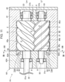
- FIG. 1 is a longitudinal cross-sectional view depicting the screw compressor according to the first embodiment of the present invention.
- FIG. 2 is a longitudinal cross-sectional view of the screw compressor according to the first embodiment depicted in FIG. 1 when viewed in the II-II arrow direction.
- FIG. 3 is a transverse cross-sectional view of the screw compressor according to the first embodiment depicted in FIG. 2 when viewed in the III-III arrow direction.
- a plurality of working chambers C are formed by lobe grooves of the rotor lobe sections 21 and 31 of the male rotor 2 and the female rotor 3 housed in the housing chamber (bore 45) and the inner wall faces (the male-side inner peripheral wall face 45a, the female-side inner peripheral wall face 45b, the suction-side inner wall face 45c, and the discharge-side inner wall face 45d) of the casing 4 surrounding the lobe grooves.
- the working chambers C gradually decrease in volume according to the progress of the rotation of both the male and female rotors 2 and 3 to compress the working fluid (compression process).
- the working chambers C communicate with the discharge port 52, and the compressed fluid in the working chambers is discharged to the outside of the casing 4 through the discharge flow path 50.
- the volume of the working chambers C eventually becomes almost zero, and the working chambers C turn into the suction process for sucking the working fluid again.
- the screw compressor 1 continuously compresses the working fluid by repeating these processes.
- the screw compressor 1 of the present embodiment is configured in such a manner that the male rotor 2 is driven by the rotary driving source to drive the female rotor 3.
- the screw compressor 1 can also be configured in such a manner that the female rotor 3 is driven by the rotary driving source to drive the male rotor 2, or both the male and female rotors 2 and 3 are synchronously driven.
- FIG. 4 is a diagram of the screw compressor according to the first embodiment when viewed in the IV-IV arrow direction depicted in FIG. 2 .
- FIG. 5 is an explanatory view depicting an example of the shape of a first flow path wall (the shape of a recessed portion defining the suction flow path) in the suction flow path of the screw compressor according to the first embodiment depicted in FIG. 4 .
- FIG. 6 is an explanatory view depicting another example of the shape of the first flow path wall (the shape of the recessed portion defining the suction flow path) in the suction flow path of the screw compressor according to the first embodiment.
- the bold arrows indicate the rotation directions of the screw rotors.
- the male-side branch flow path 72 and the female-side branch flow path 73 extend from the connection position (that is, the inflow position of the working fluid) with the introduction flow path 71 to the position of a closing part 42b of the casing 4 formed in a region on one side (lower side in FIG. 1 and FIG. 3 ) with respect to the virtual plane Pv.
- the closing part 42b closes the openings of the lobe grooves in the axial direction at the suction-side end faces 21a and 31a of the rotor lobe sections 21 and 31 of both the male and female rotors 2 and 3 when the working chambers C reach a predetermined volume by the rotation of both the male and female rotors 2 and 3.
- the region that is the connection region with the introduction flow path 71 and the branch region where they branch from each other is referred to as a starting end 75 of the male-side branch flow path 72 and the female-side branch flow path 73
- an end of the male-side branch flow path 72 on the closing part 42b side is referred to as a male-side termination end 76
- an end of the female-side branch flow path 73 on the closing part 42b side is referred to as a female-side termination end 77.
- the male-side branch flow path 72 extends along the circumferential direction of the male rotor 2 from the starting end 75 to the male-side termination end 76.
- the female-side branch flow path 73 extends along the circumferential direction of the female rotor 3 from the starting end 75 to the female-side termination end 77.
- the male-side branch flow path 72 is configured to open in the axial direction with respect to the working chambers C in the suction process.
- the flow path wall defining the male-side branch flow path 72 has a first flow path wall 81 facing the suction-side end face 21a side of the rotor lobe section 21 of the male rotor 2, a second flow path wall 82 positioned outward in a radial direction of the male rotor 2, and a third flow path wall 83 positioned inward in the radial direction of the male rotor 2 from the second flow path wall 82.
- the female-side branch flow path 73 is configured to open in the axial direction with respect to the working chambers C in the suction process.
- the flow path wall defining the female-side branch flow path 73 has a first flow path wall 91 facing the suction-side end face 31a side of the rotor lobe section 31 of the female rotor 3, a second flow path wall 92 positioned outward in a radial direction of the female rotor 3, and a third flow path wall 93 positioned radially inward with respect to the second flow path wall 92.
- the male-side branch flow path 72 and the female-side branch flow path 73 can be formed by providing recessed portions in a C shape to the end face 42a of the suction-side casing 42. That is, the first flow path walls 81 and 91 configure the bottom surfaces of the recessed portions of the suction-side casing 42 recessed in the axial direction, and the second flow path walls 82 and 92 and the third flow path walls 83 and 93 configure the side walls of the recessed portions recessed in the axial direction.
- the second flow path wall 82 of the male-side branch flow path 72 is configured to be positioned on the radially outer side of the male rotor 2 with respect to the male-side inner peripheral wall face 45a of the bore 45.
- the second flow path wall 92 of the female-side branch flow path 73 is configured to be positioned on the radially outer side of the female rotor 3 with respect to the female-side inner peripheral wall face 45b of the bore 45 as similar to the second flow path wall 82 of the male-side branch flow path 72.
- the third flow path wall 83 of the male-side branch flow path 72 is configured to substantially coincide with the lobe bottom diameter of the rotor lobe section 21 of the male rotor 2.
- the third flow path wall 93 of the female-side branch flow path 73 is also configured to substantially coincide with the lobe bottom diameter of the rotor lobe section 31 of the female rotor 3 as similar to the third flow path wall 83 of the male-side branch flow path 72.
- the interval in the rotor radial direction between the second flow path wall 82 and the third flow path wall 83 in the male-side branch flow path 72, that is, the flow path width of the male-side branch flow path 72 is configured to be substantially constant at least in a region on one side (lower side in FIG. 4 ) with respect to the virtual plane Pv.
- the interval in the rotor radial direction between the second flow path wall 92 and the third flow path wall 93 in the female-side branch flow path 73 is configured to be substantially constant at least in a region on one side (lower side in FIG. 4 ) with respect to the virtual plane Pv.
- FIG. 5 is a diagram obtained by developing the male-side branch flow path 72 and the female-side branch flow path 73 depicted in FIG. 4 along the dashed lines Dm and Df.
- the first flow path wall 81 extends such that the inclined face closer to the suction-side end face 21a of the male rotor 2 reaches the male-side termination end 76 from a position on the other side (upper side in FIG. 4 ) with respect to the virtual plane Pv.
- the bottom surface of the recessed portion forming the male-side branch flow path 72 in the suction casing 42 is configured in such a manner that the depth in the axial direction is substantially constant in the area from the point 81a to the point 81b, and gradually becomes shallower from the point 81b toward the point 81c.
- the point 81b is located at a position that is on, for example, the starting end 75 side with respect to the virtual plane Pv, is orthogonal to the virtual plane Pv, and passes through the axis line Lm of the male rotor 2.
- the first flow path wall 91 extends such that the inclined face closer to the suction-side end face 31a of the female rotor 3 reaches the female-side termination end 77 from a position on the other side (upper side in FIG. 4 ) with respect to the virtual plane Pv.
- the bottom surface of the recessed portion forming the female-side branch flow path 73 in the suction casing 42 is configured in such a manner that the depth in the axial direction is substantially constant in the area from the point 91a to the point 91b, and gradually becomes shallower from the point 91b toward the point 91c.
- the point 91b is located at a position that is located on, for example, the starting end 75 side with respect to the virtual plane Pv, is orthogonal to the virtual plane Pv, and passes through the axis line Lf of the female rotor 3.
- the first flow path wall 81 of the male-side branch flow path 72 and the first flow path wall 91 of the female-side branch flow path 73 can be configured to have shapes as depicted in, for example, FIG. 6.
- FIG. 6 is a diagram obtained by developing the male-side branch flow path 72 and the female-side branch flow path 73 depicted in FIG. 4 along the dashed lines Dm and Df.
- the first flow path wall 81 of the male-side branch flow path 72 is configured as a flat face equally distant from the suction-side end face 21a of the male rotor 2 in the area from the point 81a to the point 81b (similar to the case of FIG. 5 ), is configured as an inclined face gradually closer to the suction-side end face 21a of the male rotor 2 from the certain point 81b toward a certain point 81d before reaching the male-side termination end 76, and is configured as a flat face equally distant from the suction-side end face 21a of the male rotor 2 in an area from the certain point 81d to the point 81c positioned at the male-side termination end 76s.
- the first flow path wall 81 is configured in such a manner that a predetermined area reaching the male-side termination end 76 is a flat face.
- the bottom surface of the recessed portion forming the male-side branch flow path 72 in the suction casing 42 is configured in such a manner that the depth in the axial direction is substantially constant in the area from the point 81a to the point 81b, gradually becomes shallower from the point 81b toward the point 81d before reaching the male-side termination end 76, and is substantially constant in the area from the point 81d to the point 81c positioned at the male-side termination end 76.
- the first flow path wall 91 of the female-side branch flow path 73 is configured as a flat face equally distant from the suction-side end face 31a of the female rotor 3 in the area from the point 91a to the point 91b (similar to the case of FIG. 5 ), is configured as an inclined face gradually closer to the suction-side end face 31a of the female rotor 3 from the certain point 91b toward a certain point 91d before reaching the female-side termination end 77, and is configured as a flat face equally distant from the suction-side end face 31a of the female rotor 3 in an area from the certain point 91d to the point 91c positioned at the female-side termination end 77.
- the first flow path wall 91 is configured in such a manner that a predetermined area reaching the female-side termination end 77 is a flat face.
- the bottom surface of the recessed portion forming the female-side branch flow path 73 in the suction casing 42 is configured in such a manner that the depth in the axial direction is substantially constant in the area from the point 91a to the point 91b, gradually becomes shallower from the point 91b toward the point 91d before reaching the female-side termination end 77, and is substantially constant in the area from the point 91d to the point 91c positioned at the female-side termination end 77.
- the working fluid flowing in from the introduction flow path 71 is sucked into the working chambers C through the suction port 62 that opens in the axial direction while flowing from the starting end 75 of the male-side branch flow path 72 toward the male-side termination end 76, and also is sucked into the working chambers C through the suction port 62 that opens in the axial direction while flowing from the starting end 75 of the female-side branch flow path 73 toward the female-side termination end 77.
- FIG. 7 is a longitudinal cross-sectional view depicting the screw compressor of the comparative example to the first embodiment of the present invention.
- FIG. 8 is a longitudinal cross-sectional view of the screw compressor of the comparative example depicted in FIG. 7 when viewed in the VIII-VIII arrow direction.
- FIG. 9 is a diagram of the screw compressor of the comparative example depicted in FIG. 7 when viewed in the IX-IX arrow direction.
- FIG. 7 is a longitudinal cross-sectional view depicting the screw compressor of the comparative example to the first embodiment of the present invention.
- FIG. 8 is a longitudinal cross-sectional view of the screw compressor of the comparative example depicted in FIG. 7 when viewed in the VIII-VIII arrow direction.
- FIG. 9 is a diagram of the screw compressor of the comparative example depicted in FIG. 7 when viewed in the IX-IX arrow direction.
- FIG. 10 is an explanatory view depicting the shape of a first flow path wall (the shape of a recessed portion forming the suction flow path) in the suction flow path of the screw compressor of the comparative example depicted in FIG. 9 .
- the same reference numerals as those depicted in FIG. 1 to FIG. 6 denote the similar parts, and thus detailed description thereof is omitted.
- the main different point between a screw compressor 101 of the comparative example and the screw compressor 1 according to the present embodiment is that the shapes of a male-side branch flow path 172 and a female-side branch flow path 173 formed in a suction-side casing 142 are different in a suction flow path 160 formed in a casing 104.
- Other configurations of the screw compressor 101 of the comparative example are similar to those of the screw compressor 1 according to the present embodiment.
- a first flow path wall 181 of the male-side branch flow path 172 of the comparative example is configured to be maintained equally distant from the suction-side end face 21a of the rotor lobe section 21 of the male rotor 2 from the starting end 75 to the male-side termination end 76 as depicted in FIG. 7 to FIG. 9 .
- a first flow path wall 191 of the female-side branch flow path 173 is configured to be maintained equally distant from the suction-side end face 31a of the rotor lobe section 31 of the female rotor 3 from the starting end 75 to the female-side termination end 77.
- FIG. 10 is a diagram obtained by developing the male-side branch flow path 172 and the female-side branch flow path 173 depicted in FIG. 9 along the dashed lines Dm and Df.
- the first flow path wall 181 of the male-side branch flow path 172 is configured as a flat face equally distant from the suction-side end face 21a of the male rotor 2 in the area from the point 81a positioned in the vicinity of the starting end 75 of the male-side branch flow path 172 to the point 81c positioned at the male-side termination end 76.
- the bottom surface of the recessed portion forming the male-side branch flow path 172 in the suction-side casing 142 is configured in such a manner that the depth in the axial direction is substantially constant from the point 81a to the point 81c positioned at the male-side termination end 76.
- the first flow path wall 191 of the female-side branch flow path 173 is configured as a flat face equally distant from the suction-side end face 31a of the female rotor 3 in the area from the point 91a positioned in the vicinity of the starting end 75 of the female-side branch flow path 173 to the point 91c positioned at the female-side termination end 77.
- the bottom surface of the recessed portion forming the female-side branch flow path 173 in the suction-side casing 142 is configured in such a manner that that the depth in the axial direction is substantially constant in the area from the point 91a to the point 91c positioned at the female-side termination end 77.
- the working fluid flowing in from the introduction flow path 71 of the suction flow path 160 depicted in FIG. 7 is gradually sucked into the working chambers C through the suction port 62 (see FIG. 8 ) that opens in the axial direction while flowing from the starting end 75 of the male-side branch flow path 172 depicted in FIG. 9 toward the male-side termination end 76, and, and is also gradually sucked into the working chambers C through the suction port 62 that opens in the axial direction while flowing from the starting end 75 of the female-side branch flow path 173 toward the female-side termination end 77.
- the flow rate of the working fluid gradually decreases from the starting end 75 of the male-side branch flow path 172 toward the male-side termination end 76 by the amount sucked into the working chambers C, and gradually decreases from the starting end 75 of the female-side branch flow path 173 toward the female-side termination end 77.
- the first flow path wall 181 of the male-side branch flow path 172 is maintained substantially equally distant from the suction-side end face 21a of the male rotor 2, and the first flow path wall 191 of the female-side branch flow path 173 is maintained substantially equally distant from the suction-side end face 31a of the female rotor 3. This causes the working fluid flowing through the male-side branch flow path 172 and the female-side branch flow path 173 to decelerate from the starting end 75 side toward the female-side termination end 77 side.
- the decelerated working fluid increases, by the deceleration, in the amount of acceleration accelerated by the male rotor 2 rotating at a high speed when it is sucked into the working chambers C through the suction port 62, thereby causing an acceleration loss and deteriorating the efficiency of the screw compressor.
- the first flow path wall 81 of the male-side branch flow path 72 is configured such that at least a partial area in the range from the starting end 75 to the male-side termination end 76 is gradually closer to the rotor lobe section 21 of the male rotor 2 from the starting end 75 side toward the male-side termination end 76 side.
- the first flow path wall 91 of the female-side branch flow path 73 is configured such that at least a partial area in the range from the starting end 75 to the female-side termination end 77 is gradually closer to the rotor lobe section 31 of the female rotor 3 from the starting end 75 side toward the female-side termination end 77 side.
- the deceleration of the working fluid flowing through the male-side branch flow path 72 and the female-side branch flow path 73 can be accordingly suppressed as compared with the case of the configuration of the screw compressor 101 of the comparative example. Therefore, the acceleration amount when flowing from the male-side branch flow path 72 and the female-side branch flow path 73 into the working chambers C through the suction port 62 can be reduced, and the energy efficiency of the screw compressor 1 can be improved.
- the screw compressor 1 includes: the male rotor 2 that has the rotor lobe section 21 (first rotor lobe section) and is rotatable around the axis line Lm (first axis line); the female rotor 3 that has the rotor lobe section 31 (second rotor lobe section) and is rotatable around the axis line Lf (second axis line); and the casing 4 that has the housing chamber 45 for housing the rotor lobe section 21 (first rotor lobe section) and the rotor lobe section 31 (second rotor lobe section) in a state where they mesh with each other and forms the plurality of working chambers C together with the rotor lobe section 21 (first rotor lobe section) and the rotor lobe section 31 (second rotor lobe section).
- the casing 4 has the suction flow path 60 that introduces the working fluid from the outside of the casing 4 to the working chambers C in the suction process.
- the suction flow path 60 has: the male-side branch flow path 72 (male-side flow path) that opens in the axial direction of the male rotor 2 with respect to the working chambers C on the male rotor 2 side among the working chambers C in the suction process and that extends from the first starting end 75, which is positioned on one side with respect to the virtual plane Pv passing through the axis line Lm (first axis line) and the axis line Lf (second axis line) and is on the inflow side of the working fluid, to the male-side termination end 76 (first termination end), which is positioned on the other side with respect to the virtual plane Pv; and the female-side branch flow path 73 (female-side flow path) that opens in the axial direction of the female rotor 3 with respect to the working chambers C on the female rotor 3 side among the
- the flow path wall defining the male-side branch flow path 72 includes the first flow path wall 81 (male-side first flow path wall) that faces the suction-side end face 21a side of the rotor lobe section 21 (first rotor lobe section) and extends from the first starting end 75 to the male-side termination end 76 (first termination end), and the flow path wall defining the female-side branch flow path 73 (female-side flow path) includes the first flow path wall 91 (female-side first flow path wall) that faces the suction-side end face 31a side of the rotor lobe section 31 (second rotor lobe section) and extends from the second starting end 75 to the female-side termination end 77 (second termination end).
- the first flow path wall 81 (male-side first flow path wall) is configured such that at least a partial area in a range from the first starting end 75 to the male-side termination end 76 (first termination end) is closer to the rotor lobe section 21 (first rotor lobe section) from the first starting end 75 side toward the male-side termination end 76 (first termination end), or the first flow path wall 91 (female-side first flow path wall) is configured such that at least a partial area in a range from the second starting end 75 to the female-side termination end 77 (second termination end) is closer to the rotor lobe section 31 (second rotor lobe section) from the second starting end 75 side toward the female-side termination end 77 (second termination end).
- the first flow path wall 81 (male-side first flow path wall) in the male-side branch flow path 72 (male-side flow path), which opens in the rotor axial direction with respect to the working chambers C in the suction process, is formed so as to be closer to the rotor lobe section 21 (first rotor lobe section) toward the male-side termination end 76 (first termination end) side, or the first flow path wall 91 (female-side first flow path wall) in the female-side branch flow path 73 (female-side flow path) is formed so as to be closer to the rotor lobe section 31 (second rotor lobe section) toward the female-side termination end 77 (second termination end) side.
- the first flow path wall 81 male-side first flow path wall
- the first flow path wall 91 female-side first flow path wall
- the first flow path wall 91 female-side first flow path wall
- the first flow path wall 91 has an inclined face that is gradually closer to the rotor lobe section 31 (second rotor lobe section) from the second starting end 75 side toward the female-side termination end 77 (second termination end) side.
- the first flow path wall 81 male-side first flow path wall defining the male-side branch flow path 72 (male-side flow path) or the first flow path wall 91 (female-side first flow path wall) defining the female-side branch flow path 73 (female-side flow path) has the inclined face. This allows the flow path cross-sectional areas to be reduced without disturbing the flow of the working fluid in the male-side branch flow path 72 (male-side flow path) or the female-side branch flow path 73 (female-side flow path).
- the inclined face in the first flow path wall 81 extends from a position on the one side with respect to the virtual plane Pv to the male-side termination end 76 (first termination end), or the inclined face in the first flow path wall 91 (female-side first flow path wall) extends from a position on the one side with respect to the virtual plane Pv to the female-side termination end 77 (second termination end).
- the deceleration suppressing effect of the working fluid flowing through the male-side branch flow path 72 (male-side flow path) or the female-side branch flow path 73 (female-side flow path) can be enhanced.
- the first flow path wall 81 (male-side first flow path wall) is configured such that the inclined face extends from a position on the one side with respect to the virtual plane Pv to the certain first position 81d before reaching the male-side termination end 76 (first termination end), and such that an area from the first position 81d to the male-side termination end 76 (first termination end) is a flat face equally distant from the rotor lobe section 21 (first rotor lobe section), or the first flow path wall 91 (female-side first flow path wall) is configured such that the inclined face extends from a position on the one side with respect to the virtual plane Pv to the certain second position 91d before reaching the female-side termination end 77 (second termination end), and such that an area from the second position 91d to the female-side termination end 77 (second termination end) is a flat face equally distant from the rotor lobe section 31 (second rotor lobe section).
- the inclined face of the first flow path wall 81 (male-side first flow path wall) or the first flow path wall 91 (female-side first flow path wall) is limited before the male-side termination end 76 (first termination end) or the female-side termination end 77 (second termination end). This allows machining of the first flow path wall 81 (male-side first flow path wall) or the first flow path wall 91 (female-side first flow path wall) in the area reaching the male-side termination end 76 (first termination end) or the female-side termination end 77 (second termination end) to become easier than in the case of the inclined face.
- the male-side branch flow path 72 (male-side flow path) is configured such that the direction from the first starting end 75 to the male-side termination end 76 (first termination end) corresponds to the rotation direction of the male rotor 2
- the female-side branch flow path 73 female-side flow path
- the male-side branch flow path 72 is configured such that the direction from the second starting end 75 to the female-side termination end 77 (second termination end) corresponds to the rotation direction of the female rotor 3.
- the direction of the working fluid flowing through the male-side branch flow path 72 (male-side flow path) and the female-side branch flow path 73 (female-side flow path) corresponds to the rotation direction of the male rotor 2 and the female rotor 3. Therefore, the pressure loss of the working fluid when flowing into the working chambers C from the male-side branch flow path 72 and the female-side branch flow path 73 can be reduced.
- the casing 4 has: the main casing 41 (first casing) configured to house the rotor lobe section 21 (first rotor lobe section) and the rotor lobe section 31 (second rotor lobe section); and the suction-side casing 42 (second casing) that has the male-side branch flow path 72 (male-side flow path) and the female-side branch flow path 73 (female-side flow path), is attached to the main casing 41 (first casing), and is a member different from the main casing 41 (first casing).
- FIG. 11 is a longitudinal cross-sectional view depicting the screw compressor according to the second embodiment of the present invention.
- FIG. 12 is a transverse cross-sectional view of the screw compressor according to the second embodiment depicted in FIG. 11 when viewed in the XII-XII arrow direction.
- FIG. 13 is a diagram of the screw compressor according to the second embodiment depicted in FIG. 11 when viewed in the XIII-XIII arrow direction. It should be noted that in FIG. 11 to FIG. 13 , the same reference numerals as those depicted in FIG. 1 to FIG. 10 denote the similar parts, and thus detailed description thereof is omitted.
- the main different point between a screw compressor 1A according to the second embodiment and the screw compressor 1 according to the first embodiment is that the shapes of a male-side branch flow path 72A and a female-side branch flow path 73A formed in a suction-side casing 42A are different in a suction flow path 60A formed in a casing 4A.
- Other configurations of the screw compressor 1A of the present embodiment are similar to those of the screw compressor 1 according to the first embodiment.
- a second flow path wall 82A positioned outward in the radial direction of the male rotor 2 is configured to be partially and substantially flush with the male-side inner peripheral wall face 45a that is a wall face of the housing chamber (bore) 45 of the casing 4A when viewed from the axial direction of the male rotor 2 as depicted in FIG. 11 and FIG. 12 .
- the second flow path wall 82A is configured to be flush with the male-side inner peripheral wall face 45a of the housing chamber (bore) 45 in a range from the position of the virtual plane Pv to the male-side termination end 76.
- the position of the second flow path wall 82A in the radial direction of the male rotor 2 is the smallest position in the range where the opening that opens in the axial direction of the housing chamber (bore) 45 is not closed.
- the second flow path wall 82A of the present embodiment is configured to be closer to the third flow path wall 83 side than the second flow path wall 82 of the first embodiment. That is, as depicted in FIG. 13 , the interval in the rotor radial direction between the second flow path wall 82A and the third flow path wall 83 in the male-side branch flow path 72A (flow path width of the male-side branch flow path 72A) is narrower than the flow path width of the male-side branch flow path 72 of the first embodiment.
- the flow path cross-sectional area of the male-side branch flow path 72A is smaller than the flow path cross-sectional area of the male-side branch flow path 72 of the first embodiment. This allows a decrease in the flow speed of the working fluid flowing through the male-side branch flow path 72A to be further suppressed as compared with the first embodiment, so that the acceleration loss can be further reduced.
- a second flow path wall 92A positioned outward in the radial direction of the female rotor 3 is configured to be partially and substantially flush with the female-side inner peripheral wall face 45b that is a wall face of the housing chamber (bore) 45 of the casing 4A when viewed from the axial direction of the female rotor 3 as depicted in FIG. 11 and FIG. 12 .
- the second flow path wall 92A is configured to be flush with the female-side inner peripheral wall face 45b of the housing chamber (bore) 45 in a range from the position of the virtual plane Pv to the female-side termination end 77. That is, as depicted in FIG.
- the interval in the rotor radial direction between the second flow path wall 92A and the third flow path wall 93 in the female-side branch flow path 73A is narrower than the flow path width of the female-side branch flow path 73 of the first embodiment. Therefore, the flow path cross-sectional area of the female-side branch flow path 73A is smaller than the flow path cross-sectional area of the female-side branch flow path 73 of the first embodiment. This allows a decrease in the flow speed of the working fluid flowing through the female-side branch flow path 73A to be further suppressed as compared with the first embodiment, so that the acceleration loss can be further reduced.
- the first flow path wall 81 (male-side first flow path wall) in the male-side branch flow path 72A (male-side flow path) that opens in the rotor axial direction with respect to -the working chambers C in the suction process is formed so as to be closer to the rotor lobe section 21 (first rotor lobe section) toward the male-side termination end 76 (first termination end) side, or the first flow path wall 91 (female-side first flow path wall) in the female-side branch flow path 73A (female-side flow path) is formed so as to be closer to the rotor lobe section 31 (second rotor lobe section) toward the female-side termination end 77 (second termination end) side.
- the second flow path wall 82A that defines the male-side branch flow path 72A (male-side flow path) and is positioned outward in the radial direction of the male rotor 2 is configured to be at least partially flush with the male-side inner peripheral wall face 45a that is a wall face of the housing chamber (bore) 45, or when viewed from the axial direction of the female rotor 3, the second flow path wall 92A that defines the female-side branch flow path 73A (male-side flow path) and is positioned outward in the radial direction of the female rotor 3 is configured to be at least partially flush with the female-side inner peripheral wall face 45b that is a wall face of the housing chamber (bore) 45.
- the second flow path wall 82A of the male-side branch flow path 72A (male-side flow path) is configured to be flush with the male-side inner peripheral wall face 45a that is a wall face of the housing chamber (bore) 45 in a range from the position of the virtual plane Pv to the male-side termination end 76 (first termination end), or when viewed from the axial direction of the female rotor 3, the second flow path wall 92A of the female-side branch flow path 73A (female-side flow path) is configured to be flush with the female-side inner peripheral wall face 45b that is a wall face of the housing chamber (bore) 45 in a range from the position of the virtual plane Pv to the female-side termination end 77 (second termination end).
- the flow path cross-sectional area of the male-side branch flow path 72A (male-side flow path) or the female-side branch flow path 73A (female-side flow path) becomes smaller than that in the case of the configuration of the first embodiment. This allows the amount accelerated by the male rotor 2 or female rotor 3 rotating at a high speed when sucked from the male-side branch flow path 72A (male-side flow path) or the female-side branch flow path 73A (female-side flow path) into the working chambers C to be further suppressed, so that the deterioration of the efficiency of the screw compressor due to the acceleration loss can be suppressed.
- FIG. 14 is a transverse cross-sectional view of the screw compressor according to the third embodiment of the present invention when viewed in the arrow direction similar to the III-III arrow direction depicted in FIG. 2 .
- the same reference numerals as those depicted in FIG. 1 to FIG. 13 denote the similar parts, and thus detailed description thereof is omitted.
- the main different point between a screw compressor 1B according to the second embodiment and the screw compressor 1 according to the first embodiment is that the shapes of a male-side branch flow path 72B and a female-side branch flow path 73B formed in a suction-side casing 42B are different in a suction flow path 60B formed in a casing 4B.
- Other configurations of the screw compressor 1B of the present embodiment are similar to those of the screw compressor 1 according to the first embodiment.
- a second flow path wall 82B positioned on a radially outer side of the male rotor 2 is configured to be partially and substantially flush with the male-side inner peripheral wall face 45a that is a wall face of the housing chamber (bore) 45 of the casing 4B when viewed from the axial direction of the male rotor 2 as depicted in FIG. 14 .
- the second flow path wall 82B is configured to be gradually closer from the radially outer side of the male rotor 2 to and then be flush with the male-side inner peripheral wall face 45a of the housing chamber (bore) 45 from the position of the virtual plane Pv toward the male-side termination end 76.
- the second flow path wall 82B of the present embodiment is configured to be closer to the third flow path wall 83 toward the male-side termination end 76 side. That is, as depicted in FIG. 14 , since the interval in the rotor radial direction between the second flow path wall 82B and the third flow path wall 83 in the male-side branch flow path 72B (flow path width of the male-side branch flow path 72B) is narrower toward the male-side termination end 76 side, the flow path cross-sectional area of the male-side branch flow path 72B becomes smaller toward the male-side termination end 76 side.
- a second flow path wall 92B positioned on a radially outer side of the female rotor 3 is configured to be partially and substantially flush with the female-side inner peripheral wall face 45b that is a wall face of the housing chamber (bore) 45 of the casing 4B when viewed from the axial direction of the female rotor 3.
- the second flow path wall 92B is configured to be gradually closer from the radially outer side of the female rotor 3 to and then be flush with the female-side inner peripheral wall face 45b of the housing chamber (bore) 45 from the position of the virtual plane Pv toward the female-side termination end 77.
- the second flow path wall 92B of the present embodiment is configured to be closer to the third flow path wall 93 toward the female-side termination end 77 side. That is, as depicted in FIG. 14 , since the interval in the rotor radial direction between the second flow path wall 92B and the third flow path wall 93 in the female-side branch flow path 73B (flow path width of the female-side branch flow path 73B) is narrower toward the female-side termination end 77 side, the flow path cross-sectional area of the female-side branch flow path 73B becomes smaller toward the female-side termination end 77 side.
- the structures of the male-side branch flow path 72B and the female-side branch flow path 73B of the present embodiment are preferable in the case where it is difficult, due to the miniaturization of the screw compressor, to lengthen an area where the second flow path wall 82B and the second flow path wall 92B are flush with the male-side inner peripheral wall face 45a and the female-side inner peripheral wall face 45b, which are the wall faces of the housing chamber (bore) 45 of the casing 4B.
- the first flow path wall 81 (male-side first flow path wall) in the male-side branch flow path 72B (male-side flow path) that opens in the rotor axial direction with respect to the working chambers C in the suction process is formed so as to be closer to the rotor lobe section 21 (first rotor lobe section) toward the male-side termination end 76 (first termination end) side, or the first flow path wall 91 (female-side first flow path wall) in the female-side branch flow path 73B (female-side flow path) is formed so as to be closer to the rotor lobe section 31 (second rotor lobe section) toward the female-side termination end 77 (second termination end) side.
- the second flow path wall 82B of the male-side branch flow path 72B (male-side flow path) is configured to be gradually closer from an outer side in the radial direction of the male rotor 2 to and then be flush with the male-side inner peripheral wall face 45a, a wall face of the housing chamber (bore) 45, from the position of the virtual plane Pv toward the male-side termination end 76 (first termination end) side, or when viewed from the axial direction of the female rotor 3, the second flow path wall 92B of the female-side branch flow path 73B (female-side flow path) is configured to be gradually closer from an outer side in the radial direction of the female rotor 3 to and then be flush with the female-side inner peripheral wall face 45b, a wall face of the housing chamber (bore) 45, from the position of the virtual plane Pv toward the female-side termination end 77 (second termination end) side.
- the flow path cross-sectional area of the male-side branch flow path 72B (male-side flow path) or the female-side branch flow path 73B (female-side flow path) is gradually reduced toward the male-side termination end 76 (first termination end) side or the female-side termination end 77 (second termination end) side. This allows the deceleration of the working fluid flowing through the male-side branch flow path 72B (male-side flow path) or the female-side branch flow path 73B (female-side flow path) to be further suppressed.
- the present invention is not limited to the above-described embodiments, but includes various modified examples.
- the above embodiments have been described in detail for the purpose of clearly explaining the present invention, and are not necessarily limited to those having all the described configurations.
- a part of a configuration of one embodiment can be replaced by a configuration of another embodiment, or a configuration of one embodiment can be added to a configuration of another embodiment.
- a part of a configuration of each embodiment can be added to, deleted from, or replaced with another configuration.
- the suction port 62 of the suction flow path 60 is configured to open only in the rotor axial direction with respect to the working chambers C in the suction process.
- the suction port can also be configured to open in the rotor radial direction with respect to the working chambers C in the suction process.
- a leakage of the working fluid flowing into the working chambers occurs by centrifugal action through the suction port that opens in the rotor radial direction. Therefore, the configuration in which the suction port 62 opens only in the rotor axial direction is more preferable for suppressing the deceleration of the working fluid.
Landscapes
- Engineering & Computer Science (AREA)
- Mechanical Engineering (AREA)
- General Engineering & Computer Science (AREA)
- Applications Or Details Of Rotary Compressors (AREA)
Abstract
Description
- The present invention relates to a screw compressor, and more particularly to a screw compressor including a suction flow path that opens to working chambers in a suction process.
- A screw compressor includes a pair of male and female screw rotors that rotates while meshing with each other and a casing that houses both the screw rotors. In this compressor, a plurality of working chambers are formed by lobe grooves of both the screw rotors and an inner wall surface of the casing surrounding them. The casing is provided with a suction flow path for introducing gas (working fluid) from the outside to the working chambers and a discharge flow path for introducing compressed gas from the working chambers to the outside. The working chambers increase the volume, while moving in the axial direction with rotation of both the screw rotors, to suck gas through the suction flow path, then decrease the volume to compress the gas, and finally discharge the compressed gas through the discharge flow path. As described above, the working chambers sequentially repeat a suction process for sucking the gas through the suction flow path, a compression process for compressing the gas, and a discharge process for discharging the compressed gas through the discharge flow path.
- As the suction flow paths of the screw compressor, there are a suction flow path on the male rotor side and a suction flow path on the female rotor side that communicate with the working chambers in the suction process in the rotor axial direction, and are located on the downstream side with respect to a virtual plane passing through both center axis lines of the male and female rotors (see, for example, Patent Document 1).
- Patent Document 1:
JP-2021-28474-A - Incidentally, in a liquid flooded type screw compressor, when miniaturization is attempted in order to reduce the cost, it is inevitable to increase the speed of the screw rotors. In a liquid free type screw compressor, since the sealing effect by liquid supply as in the liquid flooded type cannot be expected, the screw rotors are often operated by high speed rotation in order to reduce a leakage loss from the working chambers.
- In the case where the screw rotors are operated by high speed rotation, the working fluid flowing into the working chambers from the suction flow path is accelerated to match the high speed rotation. If the working fluid flowing in the suction flow path decelerates, the speed of the working fluid to flow into the working chambers from the suction flow path is accordingly reduced, and thus the amount of acceleration of the working fluid increases. This means that the driving power of the screw compressor increases. Therefore, an increase in the amount of acceleration of the working fluid due to the deceleration of the working fluid flowing in the suction flow path results in an energy loss (hereinafter, referred to as an acceleration loss in some cases) and deteriorates the efficiency of the screw compressor.
- In the screw compressor described in
Patent Document 1, the working fluid flows in the suction flow path on the male rotor side and the suction flow path on the female rotor side, which communicate with the working chambers in the suction process in the rotor axial direction, from the branch side of both the flow paths toward the downstream side with respect to the virtual plane (see the void arrow inFIG. 4 of Patent Document 1). At this time, as the working fluid flows along the rotor circumferential direction from the branch side of the suction flow path on the male rotor side and the suction flow path on the female rotor side toward the downstream side, it is gradually sucked into the working chambers through an opening in the axial direction. Therefore, the flow rate of the working fluid gradually decreases from the branch side of the suction flow path on the male rotor side and the suction flow path on the female rotor side toward the downstream end by the amount sucked into the working chambers. - It is conceivable that the screw compressor described in
Patent Document 1 has a structure in which the flow path cross-sectional areas of the suction flow path on the male rotor side and the suction flow path on the female rotor side is substantially constant from the branch side to the downstream end. In the suction flow path on the male rotor side and the suction flow path on the female rotor side having such a structure, when the flow rate of the working fluid gradually decreases toward the downstream side, the flow speed of the working fluid accordingly decelerates toward the downstream side. Therefore, as described above, the deceleration of the working fluid flowing through the suction flow path on the male rotor side and the suction flow path on the female rotor side causes an acceleration loss, and thus the efficiency of the screw compressor is deteriorated. - The present invention has been made in order to solve the above problems, and an object thereof is to provide a screw compressor capable of reducing an acceleration loss caused by deceleration of working fluid flowing through a suction flow path.
- The present application includes a plurality of means for solving the above problems, and one example thereof is a screw compressor including: a male rotor that has a first rotor lobe section and is rotatable around a first axis line; a female rotor that has a second rotor lobe section and is rotatable around a second axis line; and a casing that has a housing chamber for housing the first rotor lobe section and the second rotor lobe section in a state where they mesh with each other and forms a plurality of working chambers together with the first rotor lobe section and the second rotor lobe section. Further, the casing has a suction flow path that introduces working fluid from an outside of the casing to the working chambers in a suction process. The suction flow path includes a male-side flow path that opens in an axial direction of the male rotor with respect to working chambers on the male rotor side among the working chambers in the suction process and extends from a first starting end that is positioned on one side with respect to a virtual plane passing through the first axis line and the second axis line and is on an inflow side of the working fluid to a first termination end positioned on the other side with respect to the virtual plane, and a female-side flow path that opens in an axial direction of the female rotor with respect to working chambers on the female rotor side among the working chambers in the suction process and extends from a second starting end that is positioned on the one side with respect to the virtual plane and is on the inflow side of the working fluid to a second termination end positioned on the other side with respect to the virtual plane. In addition, a flow path wall defining the male-side flow path includes a male-side first flow path wall that faces a suction-side end face side of the first rotor lobe section and extends from the first starting end to the first termination end, a flow path wall defining the female-side flow path includes a female-side first flow path wall that faces a suction-side end face side of the second rotor lobe section and extends from the second starting end to the second termination end. The male-side first flow path wall is configured such that at least a partial area in a range from the first starting end to the first termination end is closer to the first rotor lobe section from the first starting end side toward the first termination end side, or the female-side first flow path wall is configured such that at least a partial area in a range from the second starting end to the second termination end is closer to the second rotor lobe section from the second starting end side toward the second termination end side.
- According to the present invention, the male-side first flow path wall for the male-side flow path, which opens in the rotor axial direction with respect to the working chambers in the suction process, is closer to the first rotor lobe section toward the first termination end side, or the female-side first flow path wall in the female-side flow path is closer to the second rotor lobe section toward the second termination end side. Therefore, the flow path cross-sectional area of the male-side flow path decreases toward the first termination end side or the flow path cross-sectional area of the female-side flow path decreases toward the second termination end side. This causes the deceleration of the working fluid flowing through the male-side flow path or the female-side flow path to be suppressed, thereby reducing the acceleration loss caused by the deceleration of the working fluid flowing through the suction flow path.
- Problems, configurations, and effects other than those described above will be clarified by the following description of embodiments.
-
-
FIG. 1 is a longitudinal cross-sectional view depicting a screw compressor according to a first embodiment of the present invention. -
FIG. 2 is a longitudinal cross-sectional view of the screw compressor according to the first embodiment depicted inFIG. 1 when viewed in the II-II arrow direction. -
FIG. 3 is a transverse cross-sectional view of the screw compressor according to the first embodiment depicted inFIG. 2 when viewed in the III-III arrow direction. -
FIG. 4 is a diagram of the screw compressor according to the first embodiment when viewed in the IV-IV arrow direction depicted inFIG. 2 . -
FIG. 5 is an explanatory view depicting an example of the shape of a first flow path wall (the shape of a recessed portion defining a suction flow path) in the suction flow path of the screw compressor according to the first embodiment depicted inFIG. 4 . -
FIG. 6 is an explanatory view depicting another example of the shape of the first flow path wall (the shape of the recessed portion defining the suction flow path) in the suction flow path of the screw compressor according to the first embodiment. -
FIG. 7 is a longitudinal cross-sectional view depicting a screw compressor of a comparative example to the first embodiment of the present invention. -
FIG. 8 is a longitudinal cross-sectional view of the screw compressor of the comparative example depicted inFIG. 7 when viewed in the VIII-VIII arrow direction. -
FIG. 9 is a diagram of the screw compressor of the comparative example depicted inFIG. 7 when viewed in the IX-IX arrow direction. -
FIG. 10 is an explanatory view depicting the shape of a first flow path wall (the shape of a recessed portion defining a suction flow path) in the suction flow path of the screw compressor of the comparative example depicted inFIG. 9 . -
FIG. 11 is a longitudinal cross-sectional view depicting a screw compressor according to a second embodiment of the present invention. -
FIG. 12 is a transverse cross-sectional view of the screw compressor according to the second embodiment depicted inFIG. 11 when viewed in the XII-XII arrow direction. -
FIG. 13 is a diagram of the screw compressor according to the second embodiment depicted inFIG. 11 when viewed in the XIII-XIII arrow direction. -
FIG. 14 is a transverse cross-sectional view of a screw compressor according to a third embodiment of the present invention when viewed in the arrow direction similar to the III-III arrow direction depicted inFIG. 2 . - Hereinafter, embodiments of a screw compressor of the present invention will be exemplarily described by using the drawings.
- A schematic configuration of a screw compressor according to a first embodiment will be described by using
FIG. 1 to FIG. 3 .FIG. 1 is a longitudinal cross-sectional view depicting the screw compressor according to the first embodiment of the present invention.FIG. 2 is a longitudinal cross-sectional view of the screw compressor according to the first embodiment depicted inFIG. 1 when viewed in the II-II arrow direction.FIG. 3 is a transverse cross-sectional view of the screw compressor according to the first embodiment depicted inFIG. 2 when viewed in the III-III arrow direction. - In
FIG. 1 andFIG. 2 , ascrew compressor 1 includes amale rotor 2 and afemale rotor 3 as a pair of screw rotors that rotate while meshing with each other, and acasing 4 for housing both the male andfemale rotors male rotor 2 is supported by a suction-side bearing 6 and a discharge-side bearing 7 rotatably around an axis line Lm. Thefemale rotor 3 is supported by a suction-side bearing 8 and a discharge-side bearing 9 rotatably around an axis line Lf parallel to the axis line Lm of themale rotor 2. - The
male rotor 2 is configured with arotor lobe section 21 having a plurality of spiral male lobes, and a suction-side shaft section 22 and a discharge-side shaft section 23 provided at both end of therotor lobe section 21 in the axial direction. Therotor lobe section 21 has a suction-side end face 21a and a discharge-side end face 21b orthogonal to the axial direction (axis line Lm) at one end (left end inFIG. 1 andFIG. 2 ) and the other end (right end inFIG. 1 andFIG. 2 ) in the axial direction, respectively. In therotor lobe section 21, lobe grooves are formed between a plurality of male lobes. For example, the suction-side shaft section 22 is configured to penetrate thecasing 4, and is coupled to a rotary driving source, which is not depicted. For example, an electric motor is used as the rotary driving source. - The
female rotor 3 is configured with arotor lobe section 31 having a plurality of spiral female lobes, and a suction-side shaft section 32 and a discharge-side shaft section 33 provided at both end of therotor lobe section 31 in the axial direction. Therotor lobe section 31 has a suction-side end face 31a and a discharge-side end face 31b orthogonal to the axial direction (axis line Lf) at one end (left end inFIG. 2 ) and the other end (right end inFIG. 2 ) in the axial direction, respectively. In therotor lobe section 31, lobe grooves are formed between a plurality of female lobes. - The
casing 4 has a bottomed cylindricalmain casing 41 that opens on one side (left side inFIG. 1 andFIG. 2 ) in the axial direction that is the suction side, and a suction-side casing 42 that is attached to themain casing 41 so as to close the opening of themain casing 41 and is a member different from themain casing 41. Thecasing 4 has abore 45 as a housing chamber that houses therotor lobe section 21 of themale rotor 2 and therotor lobe section 31 of thefemale rotor 3 in a state where they mesh with each other. As depicted inFIG. 3 , thebore 45 is formed in themain casing 41 in such a manner that a cylindrical hole for housing therotor lobe section 21 of themale rotor 2 partially overlaps with a cylindrical hole for housing therotor lobe section 31 of thefemale rotor 3. As depicted inFIG. 1 to FIG. 3 , the wall face defining the housing chamber of thecasing 4 is configured with a male-side innerperipheral wall face 45a that covers the radially outer side of therotor lobe section 21 of themale rotor 2, a female-side innerperipheral wall face 45b that covers the radially outer side of therotor lobe section 31 of thefemale rotor 3, a suction-sideinner wall face 45c on one side (left side inFIG. 1 andFIG. 2 ) in the axial direction (a portion of anend face 42a (seeFIG. 4 to be described later) of the suction-side casing 42 on themain casing 41 side) facing the suction-side end faces 21a and 31a of therotor lobe sections female rotors inner wall face 45d on the other side (right side inFIG. 1 andFIG. 2 ) in the axial direction facing the discharge-side end faces 21b and 31b of therotor lobe sections female rotors rotor lobe sections male rotor 2 and thefemale rotor 3 housed in the housing chamber (bore 45) and the inner wall faces (the male-side innerperipheral wall face 45a, the female-side innerperipheral wall face 45b, the suction-sideinner wall face 45c, and the discharge-sideinner wall face 45d) of thecasing 4 surrounding the lobe grooves. - As depicted in
FIG. 1 andFIG. 2 , the discharge-side bearing 7 for themale rotor 2 and the discharge-side bearing 9 for thefemale rotor 3 are arranged in themain casing 41, and a discharge-side cover 43 is attached to themain casing 41 so as to cover the discharge-side bearing 7 and the discharge-side bearing 9. The suction-side bearing 6 for themale rotor 2 and the suction-side bearing 8 for thefemale rotor 3 are arranged in the suction-side casing 42. - As depicted in
FIG. 1 , thecasing 4 is provided with adischarge flow path 50 that introduces compressed gas from the working chambers C to the outside of thecasing 4. Thedischarge flow path 50 communicates the working chambers C in a discharge process with the outside of thecasing 4, and has adischarge opening 51 that is an opening of thecasing 4 on the outer wall side and adischarge port 52 that is an opening on thebore 45 side. Thedischarge port 52 is provided at a position on the other side (right side inFIG. 1 ) of thebore 45 in the axial direction and at a position on one side (lower side inFIG. 1 ) with respect to a virtual plane Pv passing through the axis lines Lm and Lf of both themale rotor 2 and thefemale rotor 3. - In addition, the
casing 4 is provided with asuction flow path 60 that introduces gas from the outside of thecasing 4 to the working chambers C. Thesuction flow path 60 communicates the outside of thecasing 4 with the working chambers C in a suction process, and has asuction opening 61 that is an opening of thecasing 4 on the outer wall side and asuction port 62 that is an opening on thebore 45 side. For example, thesuction opening 61 is provided at a position on one side (left side inFIG. 1 ) in the axial direction on the outer peripheral face of thecasing 4 and on the other side (upper side inFIG. 1 ) with respect to the virtual plane Pv. Thesuction port 62 is formed as, for example, an axial suction port that opens only in the axial direction with respect to the working chambers C in the suction process. Details of the structure such as the shape of thesuction flow path 60 in the present embodiment will be described later. - In the
screw compressor 1 configured as described above, when themale rotor 2 depicted inFIG. 2 is driven by the rotary driving source, thefemale rotor 3 is rotationally driven by themale rotor 2, and working fluid is sucked into thescrew compressor 1. The working fluid is sucked into the working chambers C through thesuction port 62 from thesuction flow path 60 depicted inFIG. 1 . The working chambers C increase or decrease in volume while moving in the axial direction with the progress of the rotation of both the male andfemale rotors FIG. 2 . Specifically, the working chambers C first gradually increase in volume according to the progress of the rotation of both the male andfemale rotors female rotors female rotors discharge port 52, and the compressed fluid in the working chambers is discharged to the outside of thecasing 4 through thedischarge flow path 50. The volume of the working chambers C eventually becomes almost zero, and the working chambers C turn into the suction process for sucking the working fluid again. Thescrew compressor 1 continuously compresses the working fluid by repeating these processes. - It should be noted that the
screw compressor 1 of the present embodiment is configured in such a manner that themale rotor 2 is driven by the rotary driving source to drive thefemale rotor 3. However, thescrew compressor 1 can also be configured in such a manner that thefemale rotor 3 is driven by the rotary driving source to drive themale rotor 2, or both the male andfemale rotors - In addition, the
screw compressor 1 of the present embodiment is illustrated as a liquid free type compressor without an injection port for injecting liquid such as oil or water into the working chambers C. However, a liquid flooded type screw compressor that injects liquid from an injection port into the working chambers C may be used. In the case where thescrew compressor 1 is of a liquid free type, it is necessary to rotate therotor lobe section 21 of themale rotor 2 and therotor lobe section 31 of thefemale rotor 3 in a non-contact state, and rotary engaging means such as a timing gear for rotationally engaging themale rotor 2 and thefemale rotor 3 with each other is provided, but the illustration of the rotary engaging means is omitted inFIG. 1 andFIG. 2 . In addition, the illustrations of systems for supplying oil to the suction-side bearings side bearings female rotors - Next, details of the structure of the suction flow path of the screw compressor according to the first embodiment will be described by using
FIG. 1 to FIG. 6 .FIG. 4 is a diagram of the screw compressor according to the first embodiment when viewed in the IV-IV arrow direction depicted inFIG. 2 .FIG. 5 is an explanatory view depicting an example of the shape of a first flow path wall (the shape of a recessed portion defining the suction flow path) in the suction flow path of the screw compressor according to the first embodiment depicted inFIG. 4 .FIG. 6 is an explanatory view depicting another example of the shape of the first flow path wall (the shape of the recessed portion defining the suction flow path) in the suction flow path of the screw compressor according to the first embodiment. InFIG. 3 andFIG. 4 , the bold arrows indicate the rotation directions of the screw rotors. - As depicted in
FIG. 1 to FIG. 4 , thesuction flow path 60 of thecasing 4 has anintroduction flow path 71 that extends from thesuction opening 61, a male-sidebranch flow path 72 that branches from theintroduction flow path 71 and extends along the circumferential direction of themale rotor 2 on the suction-side end face 21a side of therotor lobe section 21 of themale rotor 2, and a female-sidebranch flow path 73 that branches from theintroduction flow path 71 and extends along the circumferential direction of thefemale rotor 3 on the suction-side end face 31a of therotor lobe section 31 of thefemale rotor 3. As depicted inFIG. 3 , the male-sidebranch flow path 72 and the female-sidebranch flow path 73 open (communicate) with respect to the working chambers C in the suction process to form suction spaces for sucking the working fluid into the working chambers C. Theintroduction flow path 71 introduces the working fluid to the male-sidebranch flow path 72 and the female-sidebranch flow path 73 serving as the suction spaces, and is a flow path not opened to the working chambers C. Theintroduction flow path 71 is configured to be connected to the male-sidebranch flow path 72 and the female-sidebranch flow path 73 at a position on the other side (upper side inFIG. 1 andFIG. 3 ) of thecasing 4 with respect to the virtual plane Pv (that is, the position opposite to thedischarge port 52 with respect to the virtual plane Pv). For example, theintroduction flow path 71 is formed so as to extend along the rotor axial direction at a position radially outside thebore 45 of thecasing 4. - The male-side
branch flow path 72 and the female-sidebranch flow path 73 extend from the connection position (that is, the inflow position of the working fluid) with theintroduction flow path 71 to the position of aclosing part 42b of thecasing 4 formed in a region on one side (lower side inFIG. 1 andFIG. 3 ) with respect to the virtual plane Pv. Theclosing part 42b closes the openings of the lobe grooves in the axial direction at the suction-side end faces 21a and 31a of therotor lobe sections female rotors female rotors FIG. 4 , in the male-sidebranch flow path 72 and the female-sidebranch flow path 73, the region that is the connection region with theintroduction flow path 71 and the branch region where they branch from each other is referred to as a startingend 75 of the male-sidebranch flow path 72 and the female-sidebranch flow path 73, an end of the male-sidebranch flow path 72 on theclosing part 42b side is referred to as a male-side termination end 76, and an end of the female-sidebranch flow path 73 on theclosing part 42b side is referred to as a female-side termination end 77. That is, the male-sidebranch flow path 72 extends along the circumferential direction of themale rotor 2 from the startingend 75 to the male-side termination end 76. The female-sidebranch flow path 73 extends along the circumferential direction of thefemale rotor 3 from the startingend 75 to the female-side termination end 77. - As depicted in
FIG. 3 , the male-sidebranch flow path 72 is configured to open in the axial direction with respect to the working chambers C in the suction process. As depicted inFIGs. 1 ,3 , and4 , the flow path wall defining the male-sidebranch flow path 72 has a firstflow path wall 81 facing the suction-side end face 21a side of therotor lobe section 21 of themale rotor 2, a secondflow path wall 82 positioned outward in a radial direction of themale rotor 2, and a thirdflow path wall 83 positioned inward in the radial direction of themale rotor 2 from the secondflow path wall 82. As similar to the male-sidebranch flow path 72, the female-sidebranch flow path 73 is configured to open in the axial direction with respect to the working chambers C in the suction process. The flow path wall defining the female-sidebranch flow path 73 has a firstflow path wall 91 facing the suction-side end face 31a side of therotor lobe section 31 of thefemale rotor 3, a secondflow path wall 92 positioned outward in a radial direction of thefemale rotor 3, and a thirdflow path wall 93 positioned radially inward with respect to the secondflow path wall 92. As depicted inFIG. 4 , the male-sidebranch flow path 72 and the female-sidebranch flow path 73 can be formed by providing recessed portions in a C shape to theend face 42a of the suction-side casing 42. That is, the firstflow path walls side casing 42 recessed in the axial direction, and the secondflow path walls flow path walls - As depicted in
FIG. 3 , the secondflow path wall 82 of the male-sidebranch flow path 72 is configured to be positioned on the radially outer side of themale rotor 2 with respect to the male-side innerperipheral wall face 45a of thebore 45. The secondflow path wall 92 of the female-sidebranch flow path 73 is configured to be positioned on the radially outer side of thefemale rotor 3 with respect to the female-side innerperipheral wall face 45b of thebore 45 as similar to the secondflow path wall 82 of the male-sidebranch flow path 72. The thirdflow path wall 83 of the male-sidebranch flow path 72 is configured to substantially coincide with the lobe bottom diameter of therotor lobe section 21 of themale rotor 2. The thirdflow path wall 93 of the female-sidebranch flow path 73 is also configured to substantially coincide with the lobe bottom diameter of therotor lobe section 31 of thefemale rotor 3 as similar to the thirdflow path wall 83 of the male-sidebranch flow path 72. As depicted inFIG. 4 , the interval in the rotor radial direction between the secondflow path wall 82 and the thirdflow path wall 83 in the male-sidebranch flow path 72, that is, the flow path width of the male-sidebranch flow path 72 is configured to be substantially constant at least in a region on one side (lower side inFIG. 4 ) with respect to the virtual plane Pv. As similar to the above, the interval in the rotor radial direction between the secondflow path wall 92 and the thirdflow path wall 93 in the female-sidebranch flow path 73, that is, the flow path width of the female-sidebranch flow path 73 is configured to be substantially constant at least in a region on one side (lower side inFIG. 4 ) with respect to the virtual plane Pv. - The first
flow path wall 81 of the male-sidebranch flow path 72 is configured such that at least a partial area in a range from the startingend 75 to the male-side termination end 76 is gradually closer to therotor lobe section 21 of themale rotor 2 from the startingend 75 side toward the male-side termination end 76 side. As similar to the above, the firstflow path wall 91 of the female-sidebranch flow path 73 is configured such that at least a partial area in a range from the startingend 75 to the female-side termination end 77 is gradually closer to therotor lobe section 31 of thefemale rotor 3 from the startingend 75 side toward the female-side termination end 77 side. - Specifically, the first
flow path wall 81 of the male-sidebranch flow path 72 and the firstflow path wall 91 of the female-sidebranch flow path 73 have shapes as depicted in, for example,FIG. 5. FIG. 5 is a diagram obtained by developing the male-sidebranch flow path 72 and the female-sidebranch flow path 73 depicted inFIG. 4 along the dashed lines Dm and Df. - The first
flow path wall 81 of the male-sidebranch flow path 72 is configured as a flat face equally distant from the suction-side end face 21a of therotor lobe section 21 of themale rotor 2 in an area from apoint 81a positioned in the vicinity of the startingend 75 of the male-sidebranch flow path 72 to acertain point 81b is, and is configured as an inclined face gradually closer to the suction-side end face 21a of themale rotor 2 from thecertain point 81b toward apoint 81c positioned at the male-side termination end 76. That is, the firstflow path wall 81 extends such that the inclined face closer to the suction-side end face 21a of themale rotor 2 reaches the male-side termination end 76 from a position on the other side (upper side inFIG. 4 ) with respect to the virtual plane Pv. In other words, the bottom surface of the recessed portion forming the male-sidebranch flow path 72 in thesuction casing 42 is configured in such a manner that the depth in the axial direction is substantially constant in the area from thepoint 81a to thepoint 81b, and gradually becomes shallower from thepoint 81b toward thepoint 81c. Thepoint 81b is located at a position that is on, for example, the startingend 75 side with respect to the virtual plane Pv, is orthogonal to the virtual plane Pv, and passes through the axis line Lm of themale rotor 2. - As similar to the above, the first
flow path wall 91 of the female-sidebranch flow path 73 is configured as a flat face equally distant from the suction-side end face 31a of therotor lobe section 31 of thefemale rotor 3 in an area from apoint 91a positioned in the vicinity of the startingend 75 of the female-sidebranch flow path 73 to acertain point 91b, and is configured as an inclined face gradually closer to the suction-side end face 31a of thefemale rotor 3 from thecertain point 91b toward apoint 91c positioned at the female-side termination end 77. That is, the firstflow path wall 91 extends such that the inclined face closer to the suction-side end face 31a of thefemale rotor 3 reaches the female-side termination end 77 from a position on the other side (upper side inFIG. 4 ) with respect to the virtual plane Pv. In other words, the bottom surface of the recessed portion forming the female-sidebranch flow path 73 in thesuction casing 42 is configured in such a manner that the depth in the axial direction is substantially constant in the area from thepoint 91a to thepoint 91b, and gradually becomes shallower from thepoint 91b toward thepoint 91c. Thepoint 91b is located at a position that is located on, for example, the startingend 75 side with respect to the virtual plane Pv, is orthogonal to the virtual plane Pv, and passes through the axis line Lf of thefemale rotor 3. - The first
flow path wall 81 of the male-sidebranch flow path 72 and the firstflow path wall 91 of the female-sidebranch flow path 73 can be configured to have shapes as depicted in, for example,FIG. 6. FIG. 6 is a diagram obtained by developing the male-sidebranch flow path 72 and the female-sidebranch flow path 73 depicted inFIG. 4 along the dashed lines Dm and Df. - Specifically, the first
flow path wall 81 of the male-sidebranch flow path 72 is configured as a flat face equally distant from the suction-side end face 21a of themale rotor 2 in the area from thepoint 81a to thepoint 81b (similar to the case ofFIG. 5 ), is configured as an inclined face gradually closer to the suction-side end face 21a of themale rotor 2 from thecertain point 81b toward acertain point 81d before reaching the male-side termination end 76, and is configured as a flat face equally distant from the suction-side end face 21a of themale rotor 2 in an area from thecertain point 81d to thepoint 81c positioned at the male-side termination end 76s. That is, the firstflow path wall 81 is configured in such a manner that a predetermined area reaching the male-side termination end 76 is a flat face. In other words, the bottom surface of the recessed portion forming the male-sidebranch flow path 72 in thesuction casing 42 is configured in such a manner that the depth in the axial direction is substantially constant in the area from thepoint 81a to thepoint 81b, gradually becomes shallower from thepoint 81b toward thepoint 81d before reaching the male-side termination end 76, and is substantially constant in the area from thepoint 81d to thepoint 81c positioned at the male-side termination end 76. - As similar to the above, the first
flow path wall 91 of the female-sidebranch flow path 73 is configured as a flat face equally distant from the suction-side end face 31a of thefemale rotor 3 in the area from thepoint 91a to thepoint 91b (similar to the case ofFIG. 5 ), is configured as an inclined face gradually closer to the suction-side end face 31a of thefemale rotor 3 from thecertain point 91b toward acertain point 91d before reaching the female-side termination end 77, and is configured as a flat face equally distant from the suction-side end face 31a of thefemale rotor 3 in an area from thecertain point 91d to thepoint 91c positioned at the female-side termination end 77. That is, the firstflow path wall 91 is configured in such a manner that a predetermined area reaching the female-side termination end 77 is a flat face. In other words, the bottom surface of the recessed portion forming the female-sidebranch flow path 73 in thesuction casing 42 is configured in such a manner that the depth in the axial direction is substantially constant in the area from thepoint 91a to thepoint 91b, gradually becomes shallower from thepoint 91b toward thepoint 91d before reaching the female-side termination end 77, and is substantially constant in the area from thepoint 91d to thepoint 91c positioned at the female-side termination end 77. - In the
suction flow path 60 of thescrew compressor 1 configured as described above, the working fluid flowing in from theintroduction flow path 71 is sucked into the working chambers C through thesuction port 62 that opens in the axial direction while flowing from the startingend 75 of the male-sidebranch flow path 72 toward the male-side termination end 76, and also is sucked into the working chambers C through thesuction port 62 that opens in the axial direction while flowing from the startingend 75 of the female-sidebranch flow path 73 toward the female-side termination end 77. - Next, the action and effect of the screw compressor according to the first embodiment will be described in comparison with a screw compressor of a comparative example. First, the structure of a suction flow path of the screw compressor in the comparative example will be described by using
FIG. 7 to FIG. 10 .FIG. 7 is a longitudinal cross-sectional view depicting the screw compressor of the comparative example to the first embodiment of the present invention.FIG. 8 is a longitudinal cross-sectional view of the screw compressor of the comparative example depicted inFIG. 7 when viewed in the VIII-VIII arrow direction.FIG. 9 is a diagram of the screw compressor of the comparative example depicted inFIG. 7 when viewed in the IX-IX arrow direction.FIG. 10 is an explanatory view depicting the shape of a first flow path wall (the shape of a recessed portion forming the suction flow path) in the suction flow path of the screw compressor of the comparative example depicted inFIG. 9 . It should be noted that inFIG. 7 to FIG. 10 , the same reference numerals as those depicted inFIG. 1 to FIG. 6 denote the similar parts, and thus detailed description thereof is omitted. - The main different point between a
screw compressor 101 of the comparative example and thescrew compressor 1 according to the present embodiment is that the shapes of a male-sidebranch flow path 172 and a female-sidebranch flow path 173 formed in a suction-side casing 142 are different in asuction flow path 160 formed in acasing 104. Other configurations of thescrew compressor 101 of the comparative example are similar to those of thescrew compressor 1 according to the present embodiment. - Specifically, a first
flow path wall 181 of the male-sidebranch flow path 172 of the comparative example is configured to be maintained equally distant from the suction-side end face 21a of therotor lobe section 21 of themale rotor 2 from the startingend 75 to the male-side termination end 76 as depicted inFIG. 7 to FIG. 9 . As similar to the above, a firstflow path wall 191 of the female-sidebranch flow path 173 is configured to be maintained equally distant from the suction-side end face 31a of therotor lobe section 31 of thefemale rotor 3 from the startingend 75 to the female-side termination end 77. - In details, the first
flow path wall 181 of the male-sidebranch flow path 172 and the firstflow path wall 191 of the female-sidebranch flow path 173 have shapes as depicted in, for example,FIG. 10. FIG. 10 is a diagram obtained by developing the male-sidebranch flow path 172 and the female-sidebranch flow path 173 depicted inFIG. 9 along the dashed lines Dm and Df. The firstflow path wall 181 of the male-sidebranch flow path 172 is configured as a flat face equally distant from the suction-side end face 21a of themale rotor 2 in the area from thepoint 81a positioned in the vicinity of the startingend 75 of the male-sidebranch flow path 172 to thepoint 81c positioned at the male-side termination end 76. In other words, the bottom surface of the recessed portion forming the male-sidebranch flow path 172 in the suction-side casing 142 is configured in such a manner that the depth in the axial direction is substantially constant from thepoint 81a to thepoint 81c positioned at the male-side termination end 76. As similar to the above, the firstflow path wall 191 of the female-sidebranch flow path 173 is configured as a flat face equally distant from the suction-side end face 31a of thefemale rotor 3 in the area from thepoint 91a positioned in the vicinity of the startingend 75 of the female-sidebranch flow path 173 to thepoint 91c positioned at the female-side termination end 77. In other words, the bottom surface of the recessed portion forming the female-sidebranch flow path 173 in the suction-side casing 142 is configured in such a manner that that the depth in the axial direction is substantially constant in the area from thepoint 91a to thepoint 91c positioned at the female-side termination end 77. - In the
screw compressor 101 of the comparative example, the working fluid flowing in from theintroduction flow path 71 of thesuction flow path 160 depicted inFIG. 7 is gradually sucked into the working chambers C through the suction port 62 (seeFIG. 8 ) that opens in the axial direction while flowing from the startingend 75 of the male-sidebranch flow path 172 depicted inFIG. 9 toward the male-side termination end 76, and, and is also gradually sucked into the working chambers C through thesuction port 62 that opens in the axial direction while flowing from the startingend 75 of the female-sidebranch flow path 173 toward the female-side termination end 77. Therefore, the flow rate of the working fluid gradually decreases from the startingend 75 of the male-sidebranch flow path 172 toward the male-side termination end 76 by the amount sucked into the working chambers C, and gradually decreases from the startingend 75 of the female-sidebranch flow path 173 toward the female-side termination end 77. - In the
screw compressor 101 of the comparative example, the firstflow path wall 181 of the male-sidebranch flow path 172 is maintained substantially equally distant from the suction-side end face 21a of themale rotor 2, and the firstflow path wall 191 of the female-sidebranch flow path 173 is maintained substantially equally distant from the suction-side end face 31a of thefemale rotor 3. This causes the working fluid flowing through the male-sidebranch flow path 172 and the female-sidebranch flow path 173 to decelerate from the startingend 75 side toward the female-side termination end 77 side. Therefore, the decelerated working fluid increases, by the deceleration, in the amount of acceleration accelerated by themale rotor 2 rotating at a high speed when it is sucked into the working chambers C through thesuction port 62, thereby causing an acceleration loss and deteriorating the efficiency of the screw compressor. - In contrast to that, in the
screw compressor 1 according to the present embodiment, the firstflow path wall 81 of the male-sidebranch flow path 72 is configured such that at least a partial area in the range from the startingend 75 to the male-side termination end 76 is gradually closer to therotor lobe section 21 of themale rotor 2 from the startingend 75 side toward the male-side termination end 76 side. As similar to the above, the firstflow path wall 91 of the female-sidebranch flow path 73 is configured such that at least a partial area in the range from the startingend 75 to the female-side termination end 77 is gradually closer to therotor lobe section 31 of thefemale rotor 3 from the startingend 75 side toward the female-side termination end 77 side. Accordingly, since there are areas where the flow path cross-sectional areas of the male-sidebranch flow path 72 and the female-sidebranch flow path 73 decrease toward the male-side termination end 76 side and the female-side termination end 77 side, the deceleration of the working fluid flowing through the male-sidebranch flow path 72 and the female-sidebranch flow path 73 can be accordingly suppressed as compared with the case of the configuration of thescrew compressor 101 of the comparative example. Therefore, the acceleration amount when flowing from the male-sidebranch flow path 72 and the female-sidebranch flow path 73 into the working chambers C through thesuction port 62 can be reduced, and the energy efficiency of thescrew compressor 1 can be improved. - As described above, the
screw compressor 1 according to the present embodiment includes: themale rotor 2 that has the rotor lobe section 21 (first rotor lobe section) and is rotatable around the axis line Lm (first axis line); thefemale rotor 3 that has the rotor lobe section 31 (second rotor lobe section) and is rotatable around the axis line Lf (second axis line); and thecasing 4 that has thehousing chamber 45 for housing the rotor lobe section 21 (first rotor lobe section) and the rotor lobe section 31 (second rotor lobe section) in a state where they mesh with each other and forms the plurality of working chambers C together with the rotor lobe section 21 (first rotor lobe section) and the rotor lobe section 31 (second rotor lobe section). Thecasing 4 has thesuction flow path 60 that introduces the working fluid from the outside of thecasing 4 to the working chambers C in the suction process. The suction flow path 60 has: the male-side branch flow path 72 (male-side flow path) that opens in the axial direction of the male rotor 2 with respect to the working chambers C on the male rotor 2 side among the working chambers C in the suction process and that extends from the first starting end 75, which is positioned on one side with respect to the virtual plane Pv passing through the axis line Lm (first axis line) and the axis line Lf (second axis line) and is on the inflow side of the working fluid, to the male-side termination end 76 (first termination end), which is positioned on the other side with respect to the virtual plane Pv; and the female-side branch flow path 73 (female-side flow path) that opens in the axial direction of the female rotor 3 with respect to the working chambers C on the female rotor 3 side among the working chambers C in the suction process and that extends from the second starting end 75, which is positioned on the one side with respect to the virtual plane Pv and is on the inflow side of the working fluid, to the female-side termination end 77 (second termination end), which is positioned on the other side with respect to the virtual plane Pv. The flow path wall defining the male-side branch flow path 72 (male-side flow path) includes the first flow path wall 81 (male-side first flow path wall) that faces the suction-side end face 21a side of the rotor lobe section 21 (first rotor lobe section) and extends from the first startingend 75 to the male-side termination end 76 (first termination end), and the flow path wall defining the female-side branch flow path 73 (female-side flow path) includes the first flow path wall 91 (female-side first flow path wall) that faces the suction-side end face 31a side of the rotor lobe section 31 (second rotor lobe section) and extends from the second startingend 75 to the female-side termination end 77 (second termination end). The first flow path wall 81 (male-side first flow path wall) is configured such that at least a partial area in a range from the first startingend 75 to the male-side termination end 76 (first termination end) is closer to the rotor lobe section 21 (first rotor lobe section) from the first startingend 75 side toward the male-side termination end 76 (first termination end), or the first flow path wall 91 (female-side first flow path wall) is configured such that at least a partial area in a range from the second startingend 75 to the female-side termination end 77 (second termination end) is closer to the rotor lobe section 31 (second rotor lobe section) from the second startingend 75 side toward the female-side termination end 77 (second termination end). - According to this configuration, the first flow path wall 81 (male-side first flow path wall) in the male-side branch flow path 72 (male-side flow path), which opens in the rotor axial direction with respect to the working chambers C in the suction process, is formed so as to be closer to the rotor lobe section 21 (first rotor lobe section) toward the male-side termination end 76 (first termination end) side, or the first flow path wall 91 (female-side first flow path wall) in the female-side branch flow path 73 (female-side flow path) is formed so as to be closer to the rotor lobe section 31 (second rotor lobe section) toward the female-side termination end 77 (second termination end) side. This causes the flow path cross-sectional area of the male-side branch flow path 72 (male-side flow path) to decrease toward the male-side termination end 76 (first termination end) side, or the flow path cross-sectional area of the female-side branch flow path 73 (female-side flow path) to decrease toward the female-side termination end 77 (second termination end) side. Accordingly, since the deceleration of the working fluid flowing through the male-side branch flow path 72 (male-side flow path) or the female-side branch flow path 73 (female-side flow path) is suppressed, the acceleration loss caused by the deceleration of the working fluid flowing through the
suction flow path 60 can be reduced. - In addition, in the present embodiment, the first flow path wall 81 (male-side first flow path wall) has an inclined face that is gradually closer to the rotor lobe section 21 (first rotor lobe section) from the first starting
end 75 side toward the male-side termination end 76 (first termination end) side, or the first flow path wall 91 (female-side first flow path wall) has an inclined face that is gradually closer to the rotor lobe section 31 (second rotor lobe section) from the second startingend 75 side toward the female-side termination end 77 (second termination end) side. - According to this configuration, the first flow path wall 81 (male-side first flow path wall) defining the male-side branch flow path 72 (male-side flow path) or the first flow path wall 91 (female-side first flow path wall) defining the female-side branch flow path 73 (female-side flow path) has the inclined face. This allows the flow path cross-sectional areas to be reduced without disturbing the flow of the working fluid in the male-side branch flow path 72 (male-side flow path) or the female-side branch flow path 73 (female-side flow path).
- In addition, in the present embodiment, the inclined face in the first flow path wall 81 (male-side first flow path wall) extends from a position on the one side with respect to the virtual plane Pv to the male-side termination end 76 (first termination end), or the inclined face in the first flow path wall 91 (female-side first flow path wall) extends from a position on the one side with respect to the virtual plane Pv to the female-side termination end 77 (second termination end).
- According to this configuration, by reducing the flow path cross-sectional area of the male-side branch flow path 72 (male-side flow path) or the female-side branch flow path 73 (female-side flow path) to the male-side termination end 76 (first termination end) or the female-side termination end 77 (second termination end), the deceleration suppressing effect of the working fluid flowing through the male-side branch flow path 72 (male-side flow path) or the female-side branch flow path 73 (female-side flow path) can be enhanced.
- In addition, in the present embodiment, the first flow path wall 81 (male-side first flow path wall) is configured such that the inclined face extends from a position on the one side with respect to the virtual plane Pv to the certain
first position 81d before reaching the male-side termination end 76 (first termination end), and such that an area from thefirst position 81d to the male-side termination end 76 (first termination end) is a flat face equally distant from the rotor lobe section 21 (first rotor lobe section), or the first flow path wall 91 (female-side first flow path wall) is configured such that the inclined face extends from a position on the one side with respect to the virtual plane Pv to the certainsecond position 91d before reaching the female-side termination end 77 (second termination end), and such that an area from thesecond position 91d to the female-side termination end 77 (second termination end) is a flat face equally distant from the rotor lobe section 31 (second rotor lobe section). - According to this configuration, the inclined face of the first flow path wall 81 (male-side first flow path wall) or the first flow path wall 91 (female-side first flow path wall) is limited before the male-side termination end 76 (first termination end) or the female-side termination end 77 (second termination end). This allows machining of the first flow path wall 81 (male-side first flow path wall) or the first flow path wall 91 (female-side first flow path wall) in the area reaching the male-side termination end 76 (first termination end) or the female-side termination end 77 (second termination end) to become easier than in the case of the inclined face.
- In addition, in the present embodiment, the male-side branch flow path 72 (male-side flow path) is configured such that the direction from the first starting
end 75 to the male-side termination end 76 (first termination end) corresponds to the rotation direction of themale rotor 2, and the female-side branch flow path 73 (female-side flow path) is configured such that the direction from the second startingend 75 to the female-side termination end 77 (second termination end) corresponds to the rotation direction of thefemale rotor 3. - According to this configuration, the direction of the working fluid flowing through the male-side branch flow path 72 (male-side flow path) and the female-side branch flow path 73 (female-side flow path) corresponds to the rotation direction of the
male rotor 2 and thefemale rotor 3. Therefore, the pressure loss of the working fluid when flowing into the working chambers C from the male-sidebranch flow path 72 and the female-sidebranch flow path 73 can be reduced. - In addition, in the present embodiment, the
casing 4 has: the main casing 41 (first casing) configured to house the rotor lobe section 21 (first rotor lobe section) and the rotor lobe section 31 (second rotor lobe section); and the suction-side casing 42 (second casing) that has the male-side branch flow path 72 (male-side flow path) and the female-side branch flow path 73 (female-side flow path), is attached to the main casing 41 (first casing), and is a member different from the main casing 41 (first casing). - Next, a screw compressor according to a second embodiment of the present invention will be described by using
FIG. 11 to FIG. 13 .FIG. 11 is a longitudinal cross-sectional view depicting the screw compressor according to the second embodiment of the present invention.FIG. 12 is a transverse cross-sectional view of the screw compressor according to the second embodiment depicted inFIG. 11 when viewed in the XII-XII arrow direction.FIG. 13 is a diagram of the screw compressor according to the second embodiment depicted inFIG. 11 when viewed in the XIII-XIII arrow direction. It should be noted that inFIG. 11 to FIG. 13 , the same reference numerals as those depicted inFIG. 1 to FIG. 10 denote the similar parts, and thus detailed description thereof is omitted. - The main different point between a
screw compressor 1A according to the second embodiment and thescrew compressor 1 according to the first embodiment is that the shapes of a male-sidebranch flow path 72A and a female-sidebranch flow path 73A formed in a suction-side casing 42A are different in asuction flow path 60A formed in acasing 4A. Other configurations of thescrew compressor 1A of the present embodiment are similar to those of thescrew compressor 1 according to the first embodiment. - Specifically, among the flow path walls defining the male-side
branch flow path 72A, a secondflow path wall 82A positioned outward in the radial direction of themale rotor 2 is configured to be partially and substantially flush with the male-side innerperipheral wall face 45a that is a wall face of the housing chamber (bore) 45 of thecasing 4A when viewed from the axial direction of themale rotor 2 as depicted inFIG. 11 andFIG. 12 . In details, the secondflow path wall 82A is configured to be flush with the male-side innerperipheral wall face 45a of the housing chamber (bore) 45 in a range from the position of the virtual plane Pv to the male-side termination end 76. The position of the secondflow path wall 82A in the radial direction of themale rotor 2 is the smallest position in the range where the opening that opens in the axial direction of the housing chamber (bore) 45 is not closed. The secondflow path wall 82A of the present embodiment is configured to be closer to the thirdflow path wall 83 side than the secondflow path wall 82 of the first embodiment. That is, as depicted inFIG. 13 , the interval in the rotor radial direction between the second flow path wall 82A and the thirdflow path wall 83 in the male-sidebranch flow path 72A (flow path width of the male-sidebranch flow path 72A) is narrower than the flow path width of the male-sidebranch flow path 72 of the first embodiment. Therefore, the flow path cross-sectional area of the male-sidebranch flow path 72A is smaller than the flow path cross-sectional area of the male-sidebranch flow path 72 of the first embodiment. This allows a decrease in the flow speed of the working fluid flowing through the male-sidebranch flow path 72A to be further suppressed as compared with the first embodiment, so that the acceleration loss can be further reduced. - As similar to the above, among the flow path walls defining the female-side
branch flow path 73A, a secondflow path wall 92A positioned outward in the radial direction of thefemale rotor 3 is configured to be partially and substantially flush with the female-side innerperipheral wall face 45b that is a wall face of the housing chamber (bore) 45 of thecasing 4A when viewed from the axial direction of thefemale rotor 3 as depicted inFIG. 11 andFIG. 12 . In details, the secondflow path wall 92A is configured to be flush with the female-side innerperipheral wall face 45b of the housing chamber (bore) 45 in a range from the position of the virtual plane Pv to the female-side termination end 77. That is, as depicted inFIG. 13 , the interval in the rotor radial direction between the second flow path wall 92A and the thirdflow path wall 93 in the female-sidebranch flow path 73A (flow path width of the female-sidebranch flow path 73A) is narrower than the flow path width of the female-sidebranch flow path 73 of the first embodiment. Therefore, the flow path cross-sectional area of the female-sidebranch flow path 73A is smaller than the flow path cross-sectional area of the female-sidebranch flow path 73 of the first embodiment. This allows a decrease in the flow speed of the working fluid flowing through the female-sidebranch flow path 73A to be further suppressed as compared with the first embodiment, so that the acceleration loss can be further reduced. - As similar to the first embodiment, according to the second embodiment described above, the first flow path wall 81 (male-side first flow path wall) in the male-side
branch flow path 72A (male-side flow path) that opens in the rotor axial direction with respect to -the working chambers C in the suction process is formed so as to be closer to the rotor lobe section 21 (first rotor lobe section) toward the male-side termination end 76 (first termination end) side, or the first flow path wall 91 (female-side first flow path wall) in the female-sidebranch flow path 73A (female-side flow path) is formed so as to be closer to the rotor lobe section 31 (second rotor lobe section) toward the female-side termination end 77 (second termination end) side. This causes the flow path cross-sectional area of the male-sidebranch flow path 72A (male-side flow path) decreases toward the male-side termination end 76 (first termination end) side, or the flow path cross-sectional area of the female-sidebranch flow path 73A (female-side flow path) decreases toward the female-side termination end 77 (second termination end) side. Accordingly, the deceleration of the working fluid flowing through the male-sidebranch flow path 72A (male-side flow path) or the female-sidebranch flow path 73A (female-side flow path) is suppressed, and the acceleration loss caused by the deceleration of the working fluid flowing through thesuction flow path 60A can be reduced. - In addition, in the present embodiment, when viewed from the axial direction of the
male rotor 2, the secondflow path wall 82A that defines the male-sidebranch flow path 72A (male-side flow path) and is positioned outward in the radial direction of themale rotor 2 is configured to be at least partially flush with the male-side innerperipheral wall face 45a that is a wall face of the housing chamber (bore) 45, or when viewed from the axial direction of thefemale rotor 3, the secondflow path wall 92A that defines the female-sidebranch flow path 73A (male-side flow path) and is positioned outward in the radial direction of thefemale rotor 3 is configured to be at least partially flush with the female-side innerperipheral wall face 45b that is a wall face of the housing chamber (bore) 45. - According to this configuration, in flow components of the working fluid flowing from the male-side
branch flow path 72A (male-side flow path) or the female-sidebranch flow path 73A (female-side flow path) toward the working chambers C, a component in the rotor radial direction less likely to be generated, and thus the pressure loss can be reduced. - In addition, in the present embodiment, when viewed from the axial direction of the
male rotor 2, the secondflow path wall 82A of the male-sidebranch flow path 72A (male-side flow path) is configured to be flush with the male-side innerperipheral wall face 45a that is a wall face of the housing chamber (bore) 45 in a range from the position of the virtual plane Pv to the male-side termination end 76 (first termination end), or when viewed from the axial direction of thefemale rotor 3, the secondflow path wall 92A of the female-sidebranch flow path 73A (female-side flow path) is configured to be flush with the female-side innerperipheral wall face 45b that is a wall face of the housing chamber (bore) 45 in a range from the position of the virtual plane Pv to the female-side termination end 77 (second termination end). - According to this configuration, the flow path cross-sectional area of the male-side
branch flow path 72A (male-side flow path) or the female-sidebranch flow path 73A (female-side flow path) becomes smaller than that in the case of the configuration of the first embodiment. This allows the amount accelerated by themale rotor 2 orfemale rotor 3 rotating at a high speed when sucked from the male-sidebranch flow path 72A (male-side flow path) or the female-sidebranch flow path 73A (female-side flow path) into the working chambers C to be further suppressed, so that the deterioration of the efficiency of the screw compressor due to the acceleration loss can be suppressed. - Next, a screw compressor according to a third embodiment of the present invention will be described by using
FIG. 14. FIG. 14 is a transverse cross-sectional view of the screw compressor according to the third embodiment of the present invention when viewed in the arrow direction similar to the III-III arrow direction depicted inFIG. 2 . It should be noted that inFIG. 14 , the same reference numerals as those depicted inFIG. 1 to FIG. 13 denote the similar parts, and thus detailed description thereof is omitted. - The main different point between a
screw compressor 1B according to the second embodiment and thescrew compressor 1 according to the first embodiment is that the shapes of a male-sidebranch flow path 72B and a female-sidebranch flow path 73B formed in a suction-side casing 42B are different in asuction flow path 60B formed in acasing 4B. Other configurations of thescrew compressor 1B of the present embodiment are similar to those of thescrew compressor 1 according to the first embodiment. - Specifically, among the flow path walls defining the male-side
branch flow path 72B, a secondflow path wall 82B positioned on a radially outer side of themale rotor 2 is configured to be partially and substantially flush with the male-side innerperipheral wall face 45a that is a wall face of the housing chamber (bore) 45 of thecasing 4B when viewed from the axial direction of themale rotor 2 as depicted inFIG. 14 . In details, the secondflow path wall 82B is configured to be gradually closer from the radially outer side of themale rotor 2 to and then be flush with the male-side innerperipheral wall face 45a of the housing chamber (bore) 45 from the position of the virtual plane Pv toward the male-side termination end 76. The secondflow path wall 82B of the present embodiment is configured to be closer to the thirdflow path wall 83 toward the male-side termination end 76 side. That is, as depicted inFIG. 14 , since the interval in the rotor radial direction between the secondflow path wall 82B and the thirdflow path wall 83 in the male-sidebranch flow path 72B (flow path width of the male-sidebranch flow path 72B) is narrower toward the male-side termination end 76 side, the flow path cross-sectional area of the male-sidebranch flow path 72B becomes smaller toward the male-side termination end 76 side. - As similar to the above, among the flow path walls defining the female-side
branch flow path 73B, a secondflow path wall 92B positioned on a radially outer side of thefemale rotor 3 is configured to be partially and substantially flush with the female-side innerperipheral wall face 45b that is a wall face of the housing chamber (bore) 45 of thecasing 4B when viewed from the axial direction of thefemale rotor 3. In details, the secondflow path wall 92B is configured to be gradually closer from the radially outer side of thefemale rotor 3 to and then be flush with the female-side innerperipheral wall face 45b of the housing chamber (bore) 45 from the position of the virtual plane Pv toward the female-side termination end 77. The secondflow path wall 92B of the present embodiment is configured to be closer to the thirdflow path wall 93 toward the female-side termination end 77 side. That is, as depicted inFIG. 14 , since the interval in the rotor radial direction between the secondflow path wall 92B and the thirdflow path wall 93 in the female-sidebranch flow path 73B (flow path width of the female-sidebranch flow path 73B) is narrower toward the female-side termination end 77 side, the flow path cross-sectional area of the female-sidebranch flow path 73B becomes smaller toward the female-side termination end 77 side. - The structures of the male-side
branch flow path 72B and the female-sidebranch flow path 73B of the present embodiment are preferable in the case where it is difficult, due to the miniaturization of the screw compressor, to lengthen an area where the secondflow path wall 82B and the secondflow path wall 92B are flush with the male-side innerperipheral wall face 45a and the female-side innerperipheral wall face 45b, which are the wall faces of the housing chamber (bore) 45 of thecasing 4B. - As similar to the first embodiment, according to the third embodiment described above, the first flow path wall 81 (male-side first flow path wall) in the male-side
branch flow path 72B (male-side flow path) that opens in the rotor axial direction with respect to the working chambers C in the suction process is formed so as to be closer to the rotor lobe section 21 (first rotor lobe section) toward the male-side termination end 76 (first termination end) side, or the first flow path wall 91 (female-side first flow path wall) in the female-sidebranch flow path 73B (female-side flow path) is formed so as to be closer to the rotor lobe section 31 (second rotor lobe section) toward the female-side termination end 77 (second termination end) side. This causes the flow path cross-sectional area of the male-sidebranch flow path 72B (male-side flow path) decreases toward the male-side termination end 76 (first termination end) side, or the flow path cross-sectional area of the female-sidebranch flow path 73B (female-side flow path) decreases toward the female-side termination end 77 (second termination end) side. Accordingly, the deceleration of the working fluid flowing through the male-sidebranch flow path 72B (male-side flow path) or the female-sidebranch flow path 73B (female-side flow path) is suppressed, and the acceleration loss caused by the deceleration of the working fluid flowing through thesuction flow path 60B can be reduced. - In addition, in the present embodiment, when viewed from the axial direction of the
male rotor 2, the secondflow path wall 82B of the male-sidebranch flow path 72B (male-side flow path) is configured to be gradually closer from an outer side in the radial direction of themale rotor 2 to and then be flush with the male-side innerperipheral wall face 45a, a wall face of the housing chamber (bore) 45, from the position of the virtual plane Pv toward the male-side termination end 76 (first termination end) side, or when viewed from the axial direction of thefemale rotor 3, the secondflow path wall 92B of the female-sidebranch flow path 73B (female-side flow path) is configured to be gradually closer from an outer side in the radial direction of thefemale rotor 3 to and then be flush with the female-side innerperipheral wall face 45b, a wall face of the housing chamber (bore) 45, from the position of the virtual plane Pv toward the female-side termination end 77 (second termination end) side. - According to this configuration, the flow path cross-sectional area of the male-side
branch flow path 72B (male-side flow path) or the female-sidebranch flow path 73B (female-side flow path) is gradually reduced toward the male-side termination end 76 (first termination end) side or the female-side termination end 77 (second termination end) side. This allows the deceleration of the working fluid flowing through the male-sidebranch flow path 72B (male-side flow path) or the female-sidebranch flow path 73B (female-side flow path) to be further suppressed. - It should be noted that the present invention is not limited to the above-described embodiments, but includes various modified examples. The above embodiments have been described in detail for the purpose of clearly explaining the present invention, and are not necessarily limited to those having all the described configurations. For example, a part of a configuration of one embodiment can be replaced by a configuration of another embodiment, or a configuration of one embodiment can be added to a configuration of another embodiment. In addition, a part of a configuration of each embodiment can be added to, deleted from, or replaced with another configuration.
- For example, in the above-described embodiments, the example in which the
suction port 62 of thesuction flow path 60 is configured to open only in the rotor axial direction with respect to the working chambers C in the suction process has been denoted. However, the suction port can also be configured to open in the rotor radial direction with respect to the working chambers C in the suction process. However, in the case of this configuration, a leakage of the working fluid flowing into the working chambers occurs by centrifugal action through the suction port that opens in the rotor radial direction. Therefore, the configuration in which thesuction port 62 opens only in the rotor axial direction is more preferable for suppressing the deceleration of the working fluid. -
- 1, 1A, 1B: Screw compressor
- 2: Male rotor
- 3: Female rotor
- 4, 4A, 4B: Casing
- 21: Rotor lobe section (first rotor lobe section)
- 31: Rotor lobe section (second rotor lobe section)
- 41: Main casing (first casing)
- 42, 42A, 42B: Suction-side casing (second casing)
- 45: Bore (housing chamber)
- 45a: Male-side inner peripheral wall face (wall face of housing chamber)
- 45b: Female-side inner peripheral wall face (wall face of housing chamber)
- 60, 60A, 60B: Suction flow path
- 72, 72A, 72B: Male-side branch flow path (male-side flow path)
- 73, 73A, 73B: Female-side branch flow path (female-side flow path)
- 75: Starting end (first starting end, second starting end)
- 76: Male-side termination end (first termination end)
- 77: Female-side termination end (second termination end)
- 81: First flow path wall (male-side first flow path wall)
- 82, 82A, 82B: Second flow path wall
- 81d: Certain point (certain first position)
- 91: First flow path wall (female-side first flow path wall)
- 91d: Certain point (certain second position)
- 92, 92A, 92B: Second flow path wall
- C: Working chamber
- Lm: Axis line (first axis line)
- Lf: Axis line (second axis line)
- Pt: Virtual plane
Claims (10)
- A screw compressor comprising:a male rotor that has a first rotor lobe section and is rotatable around a first axis line;a female rotor that has a second rotor lobe section and is rotatable around a second axis line; anda casing that has a housing chamber for housing the first rotor lobe section and the second rotor lobe section in a state where they mesh with each other, and forms a plurality of working chambers together with the first rotor lobe section and the second rotor lobe section, whereinthe casing has a suction flow path that introduces working fluid from an outside of the casing to working chambers in a suction process,the suction flow path includesa male-side flow path that opens in an axial direction of the male rotor with respect to working chambers on the male rotor side among the working chambers in the suction process and that extends from a first starting end to a first termination end, the first starting end being positioned on one side with respect to a virtual plane passing through the first axis line and the second axis line and being on an inflow side of the working fluid, the first termination end being positioned on other side with respect to the virtual plane, anda female-side flow path that opens in an axial direction of the female rotor with respect to working chambers on the female rotor side among the working chambers in the suction process and that extends from a second starting end to a second termination end, the second starting end being positioned on the one side with respect to the virtual plane and being on the inflow side of the working fluid, the second termination end being positioned on the other side with respect to the virtual plane,a flow path wall defining the male-side flow path includes a male-side first flow path wall that faces a suction-side end face side of the first rotor lobe section and extends from the first starting end to the first termination end,a flow path wall defining the female-side flow path includes a female-side first flow path wall that faces a suction-side end face side of the second rotor lobe section and extends from the second starting end to the second termination end, andthe male-side first flow path wall is configured such that at least a partial area in a range from the first starting end to the first termination end is closer to the first rotor lobe section from the first starting end side toward the first termination end side, or the female-side first flow path wall is configured such that at least a partial area in a range from the second starting end to the second termination end is closer to the second rotor lobe section from the second starting end side toward the second termination end side.
- The screw compressor according to claim 1, whereinthe male-side first flow path wall has an inclined face that is gradually closer to the first rotor lobe section from the first starting end side toward the first termination end side, orthe female-side first flow path wall has an inclined face that is gradually closer to the second rotor lobe section from the second starting end side toward the second termination end side.
- The screw compressor according to claim 2, whereinthe inclined face of the male-side first flow path wall extends from a position on the one side with respect to the virtual plane to the first termination end, orthe inclined face of the female-side first flow path wall extends from a position on the one side with respect to the virtual plane to the second termination end.
- The screw compressor according to claim 2, whereinthe male-side first flow path wall is configured such that the inclined face extends from a position on the one side with respect to the virtual plane to a certain first position before reaching the first termination end, and such that an area from the first position to the first termination end is a flat face equally distant from the first rotor lobe section, orthe female-side first flow path wall is configured such that the inclined face extends from a position on the one side with respect to the virtual plane to a certain second position before reaching the second termination end, and such that an area from the second position to the second termination end is equally distant from the second rotor lobe section.
- The screw compressor according to claim 1, whereina second flow path wall that defines the male-side flow path and is positioned outward in a radial direction of the male rotor is configured to, at least partially, be flush with a wall face of the housing chamber when viewed from the axial direction of the male rotor, ora second flow path wall that defines the female-side flow path and is positioned outward in a radial direction of the female rotor is configured to, at least partially, be flush with the wall face of the housing chamber when viewed from the axial direction of the female rotor.
- The screw compressor according to claim 5, whereinthe second flow path wall of the male-side flow path is configured to be gradually closer from an outer side in the radial direction of the male rotor to and then be flush with the wall face of the housing chamber from a position of the virtual plane toward the first termination end, when viewed from the axial direction of the male rotor, orthe second flow path wall of the female-side flow path is configured to be gradually closer from an outer side in the radial direction of the female rotor to and then be flush with the wall face of the housing chamber from the position of the virtual plane toward the second termination end, when viewed from the axial direction of the female rotor.
- The screw compressor according to claim 5, whereinthe second flow path wall of the male-side flow path is configured to be flush with the wall face of the housing chamber in a range from a position of the virtual plane to the first termination end when viewed from the axial direction of the male rotor, orthe second flow path wall of the female-side flow path is configured to be flush with the wall face of the housing chamber in a range from the position of the virtual plane to the second termination end when viewed from the axial direction of the female rotor.
- The screw compressor according to claim 1, whereinthe male-side flow path is configured such that a direction from the first starting end to the first termination end corresponds to a rotation direction of the male rotor, andthe female-side flow path is configured such that a direction from the second starting end to the second termination end corresponds to a rotation direction of the female rotor.
- The screw compressor according to claim 1, whereinthe casing hasa first casing configured to house the first rotor lobe section and the second rotor lobe section, anda second casing having the male-side flow path and the female-side flow path, the second casing being a member different from the first casing and being attached to the first casing.
- The screw compressor according to claim 1,
wherein
the suction flow path is configured to open only in the axial directions of the male rotor and the female rotor with respect to the working chambers in the suction process.
Applications Claiming Priority (2)
| Application Number | Priority Date | Filing Date | Title |
|---|---|---|---|
| JP2022040336A JP7757216B2 (en) | 2022-03-15 | 2022-03-15 | Screw Compressor |
| PCT/JP2023/008100 WO2023176517A1 (en) | 2022-03-15 | 2023-03-03 | Screw compressor |
Publications (2)
| Publication Number | Publication Date |
|---|---|
| EP4495426A1 true EP4495426A1 (en) | 2025-01-22 |
| EP4495426A4 EP4495426A4 (en) | 2026-03-25 |
Family
ID=88023661
Family Applications (1)
| Application Number | Title | Priority Date | Filing Date |
|---|---|---|---|
| EP23770474.7A Pending EP4495426A4 (en) | 2022-03-15 | 2023-03-03 | SCREW COMPRESSOR |
Country Status (5)
| Country | Link |
|---|---|
| US (1) | US12442374B2 (en) |
| EP (1) | EP4495426A4 (en) |
| JP (1) | JP7757216B2 (en) |
| CN (1) | CN118696173A (en) |
| WO (1) | WO2023176517A1 (en) |
Family Cites Families (7)
| Publication number | Priority date | Publication date | Assignee | Title |
|---|---|---|---|---|
| JPS5996494A (en) * | 1982-11-25 | 1984-06-02 | Hitachi Ltd | Screw hydraulic machine |
| JP2000337283A (en) * | 1999-05-28 | 2000-12-05 | Tochigi Fuji Ind Co Ltd | Screw compressor |
| US6659729B2 (en) * | 2001-02-15 | 2003-12-09 | Mayekawa Mfg. Co., Ltd. | Screw compressor equipment for accommodating low compression ratio and pressure variation and the operation method thereof |
| JP5177081B2 (en) | 2009-06-01 | 2013-04-03 | 株式会社日立プラントテクノロジー | Screw compressor |
| JP7189749B2 (en) | 2018-12-04 | 2022-12-14 | 株式会社日立産機システム | screw compressor |
| WO2020162046A1 (en) * | 2019-02-06 | 2020-08-13 | 株式会社日立産機システム | Multi-stage screw compressor |
| JP7271392B2 (en) * | 2019-10-30 | 2023-05-11 | 株式会社日立産機システム | Feed screw compressor |
-
2022
- 2022-03-15 JP JP2022040336A patent/JP7757216B2/en active Active
-
2023
- 2023-03-03 EP EP23770474.7A patent/EP4495426A4/en active Pending
- 2023-03-03 WO PCT/JP2023/008100 patent/WO2023176517A1/en not_active Ceased
- 2023-03-03 US US18/843,632 patent/US12442374B2/en active Active
- 2023-03-03 CN CN202380021720.3A patent/CN118696173A/en active Pending
Also Published As
| Publication number | Publication date |
|---|---|
| US20250188929A1 (en) | 2025-06-12 |
| JP2023135232A (en) | 2023-09-28 |
| JP7757216B2 (en) | 2025-10-21 |
| CN118696173A (en) | 2024-09-24 |
| EP4495426A4 (en) | 2026-03-25 |
| WO2023176517A1 (en) | 2023-09-21 |
| US12442374B2 (en) | 2025-10-14 |
Similar Documents
| Publication | Publication Date | Title |
|---|---|---|
| CN108691765B (en) | External rotation wheel line vacuum pump | |
| US7758326B2 (en) | Scroll fluid machine | |
| US8936450B2 (en) | Roots fluid machine with reduced gas leakage | |
| CN103502646B (en) | Scroll compressor | |
| US9581156B2 (en) | Gear pump including an inner rotor having a plurality of teeth | |
| CN101925744B (en) | Rotary fluid machine | |
| JP2013241851A (en) | Gas compressor | |
| US20100047104A1 (en) | Fluid machine | |
| EP3067563A1 (en) | Claw pump | |
| CN101900120B (en) | Screw compressor | |
| EP2871366A1 (en) | Rotary compressor | |
| KR20060024934A (en) | Multi-cylinder rotary compressor | |
| CN113700648A (en) | Rotary compressor | |
| US12442374B2 (en) | Screw compressor with improved suction flow | |
| CN116804407A (en) | Roots pump | |
| AU2013338109A1 (en) | Port plate of a flat sided liquid ring pump having a gas scavenge passage therein | |
| CN113167275A (en) | Screw compressor | |
| US6663367B2 (en) | Shaft seal structure of vacuum pumps | |
| US10267311B2 (en) | Horizontal step scroll compressor with bypass ports | |
| CN112673176B (en) | Vane Pump Unit | |
| EP2039936A1 (en) | Scroll compressor | |
| GB2558954B (en) | Pump sealing | |
| US11668302B2 (en) | Scroll compressor having oil supply passages in fluid communication with compression chambers | |
| JP2003278673A (en) | Screw compressor | |
| JP2003184776A (en) | Compressor |
Legal Events
| Date | Code | Title | Description |
|---|---|---|---|
| STAA | Information on the status of an ep patent application or granted ep patent |
Free format text: STATUS: THE INTERNATIONAL PUBLICATION HAS BEEN MADE |
|
| PUAI | Public reference made under article 153(3) epc to a published international application that has entered the european phase |
Free format text: ORIGINAL CODE: 0009012 |
|
| STAA | Information on the status of an ep patent application or granted ep patent |
Free format text: STATUS: REQUEST FOR EXAMINATION WAS MADE |
|
| 17P | Request for examination filed |
Effective date: 20241015 |
|
| AK | Designated contracting states |
Kind code of ref document: A1 Designated state(s): AL AT BE BG CH CY CZ DE DK EE ES FI FR GB GR HR HU IE IS IT LI LT LU LV MC ME MK MT NL NO PL PT RO RS SE SI SK SM TR |
|
| DAV | Request for validation of the european patent (deleted) | ||
| DAX | Request for extension of the european patent (deleted) | ||
| A4 | Supplementary search report drawn up and despatched |
Effective date: 20260225 |
|
| RIC1 | Information provided on ipc code assigned before grant |
Ipc: F04C 18/16 20060101AFI20260219BHEP Ipc: F04C 29/00 20060101ALI20260219BHEP Ipc: F04C 29/12 20060101ALI20260219BHEP |