EP4495412A1 - Fuel supply system for supplying a fuel emulsion to a fuel injection system of an engine - Google Patents
Fuel supply system for supplying a fuel emulsion to a fuel injection system of an engine Download PDFInfo
- Publication number
- EP4495412A1 EP4495412A1 EP24184666.6A EP24184666A EP4495412A1 EP 4495412 A1 EP4495412 A1 EP 4495412A1 EP 24184666 A EP24184666 A EP 24184666A EP 4495412 A1 EP4495412 A1 EP 4495412A1
- Authority
- EP
- European Patent Office
- Prior art keywords
- fuel
- emulsion
- supply system
- blending unit
- fuel supply
- Prior art date
- Legal status (The legal status is an assumption and is not a legal conclusion. Google has not performed a legal analysis and makes no representation as to the accuracy of the status listed.)
- Pending
Links
Images



Classifications
-
- F—MECHANICAL ENGINEERING; LIGHTING; HEATING; WEAPONS; BLASTING
- F02—COMBUSTION ENGINES; HOT-GAS OR COMBUSTION-PRODUCT ENGINE PLANTS
- F02M—SUPPLYING COMBUSTION ENGINES IN GENERAL WITH COMBUSTIBLE MIXTURES OR CONSTITUENTS THEREOF
- F02M21/00—Apparatus for supplying engines with non-liquid fuels, e.g. gaseous fuels stored in liquid form
- F02M21/02—Apparatus for supplying engines with non-liquid fuels, e.g. gaseous fuels stored in liquid form for gaseous fuels
- F02M21/0203—Apparatus for supplying engines with non-liquid fuels, e.g. gaseous fuels stored in liquid form for gaseous fuels characterised by the type of gaseous fuel
- F02M21/0206—Non-hydrocarbon fuels, e.g. hydrogen, ammonia or carbon monoxide
-
- F—MECHANICAL ENGINEERING; LIGHTING; HEATING; WEAPONS; BLASTING
- F02—COMBUSTION ENGINES; HOT-GAS OR COMBUSTION-PRODUCT ENGINE PLANTS
- F02M—SUPPLYING COMBUSTION ENGINES IN GENERAL WITH COMBUSTIBLE MIXTURES OR CONSTITUENTS THEREOF
- F02M25/00—Engine-pertinent apparatus for adding non-fuel substances or small quantities of secondary fuel to combustion-air, main fuel or fuel-air mixture
-
- F—MECHANICAL ENGINEERING; LIGHTING; HEATING; WEAPONS; BLASTING
- F02—COMBUSTION ENGINES; HOT-GAS OR COMBUSTION-PRODUCT ENGINE PLANTS
- F02D—CONTROLLING COMBUSTION ENGINES
- F02D19/00—Controlling engines characterised by their use of non-liquid fuels, pluralities of fuels, or non-fuel substances added to the combustible mixtures
- F02D19/06—Controlling engines characterised by their use of non-liquid fuels, pluralities of fuels, or non-fuel substances added to the combustible mixtures peculiar to engines working with pluralities of fuels, e.g. alternatively with light and heavy fuel oil, other than engines indifferent to the fuel consumed
- F02D19/0639—Controlling engines characterised by their use of non-liquid fuels, pluralities of fuels, or non-fuel substances added to the combustible mixtures peculiar to engines working with pluralities of fuels, e.g. alternatively with light and heavy fuel oil, other than engines indifferent to the fuel consumed characterised by the type of fuels
- F02D19/0642—Controlling engines characterised by their use of non-liquid fuels, pluralities of fuels, or non-fuel substances added to the combustible mixtures peculiar to engines working with pluralities of fuels, e.g. alternatively with light and heavy fuel oil, other than engines indifferent to the fuel consumed characterised by the type of fuels at least one fuel being gaseous, the other fuels being gaseous or liquid at standard conditions
- F02D19/0644—Controlling engines characterised by their use of non-liquid fuels, pluralities of fuels, or non-fuel substances added to the combustible mixtures peculiar to engines working with pluralities of fuels, e.g. alternatively with light and heavy fuel oil, other than engines indifferent to the fuel consumed characterised by the type of fuels at least one fuel being gaseous, the other fuels being gaseous or liquid at standard conditions the gaseous fuel being hydrogen, ammonia or carbon monoxide
-
- F—MECHANICAL ENGINEERING; LIGHTING; HEATING; WEAPONS; BLASTING
- F02—COMBUSTION ENGINES; HOT-GAS OR COMBUSTION-PRODUCT ENGINE PLANTS
- F02D—CONTROLLING COMBUSTION ENGINES
- F02D19/00—Controlling engines characterised by their use of non-liquid fuels, pluralities of fuels, or non-fuel substances added to the combustible mixtures
- F02D19/06—Controlling engines characterised by their use of non-liquid fuels, pluralities of fuels, or non-fuel substances added to the combustible mixtures peculiar to engines working with pluralities of fuels, e.g. alternatively with light and heavy fuel oil, other than engines indifferent to the fuel consumed
- F02D19/08—Controlling engines characterised by their use of non-liquid fuels, pluralities of fuels, or non-fuel substances added to the combustible mixtures peculiar to engines working with pluralities of fuels, e.g. alternatively with light and heavy fuel oil, other than engines indifferent to the fuel consumed simultaneously using pluralities of fuels
-
- F—MECHANICAL ENGINEERING; LIGHTING; HEATING; WEAPONS; BLASTING
- F02—COMBUSTION ENGINES; HOT-GAS OR COMBUSTION-PRODUCT ENGINE PLANTS
- F02D—CONTROLLING COMBUSTION ENGINES
- F02D19/00—Controlling engines characterised by their use of non-liquid fuels, pluralities of fuels, or non-fuel substances added to the combustible mixtures
- F02D19/06—Controlling engines characterised by their use of non-liquid fuels, pluralities of fuels, or non-fuel substances added to the combustible mixtures peculiar to engines working with pluralities of fuels, e.g. alternatively with light and heavy fuel oil, other than engines indifferent to the fuel consumed
- F02D19/08—Controlling engines characterised by their use of non-liquid fuels, pluralities of fuels, or non-fuel substances added to the combustible mixtures peculiar to engines working with pluralities of fuels, e.g. alternatively with light and heavy fuel oil, other than engines indifferent to the fuel consumed simultaneously using pluralities of fuels
- F02D19/081—Adjusting the fuel composition or mixing ratio; Transitioning from one fuel to the other
-
- F—MECHANICAL ENGINEERING; LIGHTING; HEATING; WEAPONS; BLASTING
- F02—COMBUSTION ENGINES; HOT-GAS OR COMBUSTION-PRODUCT ENGINE PLANTS
- F02M—SUPPLYING COMBUSTION ENGINES IN GENERAL WITH COMBUSTIBLE MIXTURES OR CONSTITUENTS THEREOF
- F02M21/00—Apparatus for supplying engines with non-liquid fuels, e.g. gaseous fuels stored in liquid form
- F02M21/02—Apparatus for supplying engines with non-liquid fuels, e.g. gaseous fuels stored in liquid form for gaseous fuels
- F02M21/0203—Apparatus for supplying engines with non-liquid fuels, e.g. gaseous fuels stored in liquid form for gaseous fuels characterised by the type of gaseous fuel
- F02M21/0209—Hydrocarbon fuels, e.g. methane or acetylene
-
- F—MECHANICAL ENGINEERING; LIGHTING; HEATING; WEAPONS; BLASTING
- F02—COMBUSTION ENGINES; HOT-GAS OR COMBUSTION-PRODUCT ENGINE PLANTS
- F02M—SUPPLYING COMBUSTION ENGINES IN GENERAL WITH COMBUSTIBLE MIXTURES OR CONSTITUENTS THEREOF
- F02M21/00—Apparatus for supplying engines with non-liquid fuels, e.g. gaseous fuels stored in liquid form
- F02M21/02—Apparatus for supplying engines with non-liquid fuels, e.g. gaseous fuels stored in liquid form for gaseous fuels
- F02M21/0203—Apparatus for supplying engines with non-liquid fuels, e.g. gaseous fuels stored in liquid form for gaseous fuels characterised by the type of gaseous fuel
- F02M21/0215—Mixtures of gaseous fuels; Natural gas; Biogas; Mine gas; Landfill gas
-
- F—MECHANICAL ENGINEERING; LIGHTING; HEATING; WEAPONS; BLASTING
- F02—COMBUSTION ENGINES; HOT-GAS OR COMBUSTION-PRODUCT ENGINE PLANTS
- F02M—SUPPLYING COMBUSTION ENGINES IN GENERAL WITH COMBUSTIBLE MIXTURES OR CONSTITUENTS THEREOF
- F02M25/00—Engine-pertinent apparatus for adding non-fuel substances or small quantities of secondary fuel to combustion-air, main fuel or fuel-air mixture
- F02M25/10—Engine-pertinent apparatus for adding non-fuel substances or small quantities of secondary fuel to combustion-air, main fuel or fuel-air mixture adding acetylene, non-waterborne hydrogen, non-airborne oxygen, or ozone
Definitions
- the present invention refers to a fuel supply system for supplying a fuel emulsion to a fuel injection system of an internal combustion engine, in particular of a marine engine.
- the primary fuel and the alternative fuel may be two normally immiscible liquids which, when mixed together, form an emulsion.
- the phase segregation in such an emulsion may affect the combustion process in the engine and may thus result in unfavorable operating conditions.
- a fuel supply system of an internal combustion engine in particular of a marine diesel engine, is provided.
- the fuel supply system is intended for supplying a fuel emulsion to a fuel injection system of the engine and, for doing so, comprises at least one blending unit comprising a static mixer and configured to blend a primary fuel and a secondary fuel to provide the fuel emulsion prior to being supplied to the fuel injection system.
- Figure 1a depicts an internal combustion engine system 10 of a vessel including a fuel supply system 12 and an internal combustion engine 14, referred to as "the engine” in the following.
- the engine 14 is a medium speed combustion engine provided in the form of a marine diesel engine.
- the present invention is not limited to this specific application and may be applied in different technical fields and applications, such as in internal combustion engine systems used in power plants or vehicles as a main or auxiliary engine or the like.
- the suggested fuel supply system 12 is not limited to be used in combination with the engine 14 of the shown configuration, but rather may be applied to any suitable internal combustion engines, such as gasoline engines.
- the engine 14 includes a plurality of cylinders and a corresponding number of piston assemblies disposed therein (not shown).
- the engine 14 may include any number of cylinders which may be arranged according an "in-line” configuration, a "V-configuration", or any other known cylinder configuration.
- Each cylinder is provided with a combustion chamber delimited by a cylinder wall and a piston accommodated therein.
- each one of the combustion chambers is supplied with a fuel medium and intake air which are to be ignited therein so as to produce high-temperature and high-pressure gases, thereby applying forces to and thus axially move the associated pistons. In this way, chemical energy is transformed into mechanical energy.
- the engine 14 For supplying the fuel medium into the combustion chambers, the engine 14 comprises a fuel injection system 16 configured for injecting the fuel medium, in particular a liquid fuel medium into the respective combustion chambers of the engine 14.
- the fuel injection system 16 will be further specified below with reference to Fig. 1a .
- the engine For supplying intake air into the combustion chambers, the engine further comprises an air intake system (not shown) comprising a plurality of air intake valves opening into the respective combustion chambers and configured for selectively directing intake air into the combustion chambers.
- an air intake system (not shown) comprising a plurality of air intake valves opening into the respective combustion chambers and configured for selectively directing intake air into the combustion chambers.
- the engine 14 further comprises an exhaust gas system (not shown) comprising a plurality of exhaust gas valves configured for selectively expelling exhaust gases from the combustion chambers.
- the fuel injection system 16 comprises a fuel receiving line 18 which is configured to receive a fuel medium from the fuel supply system 12. Upon receiving the fuel medium, the fuel receiving line 18 is configured to guide the received fuel medium to a plurality of injection pumps 20 which pressurize and inject the fuel medium into the respective combustion chambers of the engine 14.
- the number of injection pumps 20 may correspond to the number of cylinders of the engine 14.
- the fuel injection pumps 20 are connected to a fuel return line 22 via a fuel bypass line 24 to direct unspent fuel, i.e. fuel passing the injection pumps 20 without being injected into the combustion chambers, to the fuel supply system 12.
- a common rail and an associated high pressure pump may be used to supply pressurized fuel medium to the combustion chambers via corresponding injectors.
- the fuel injection system 16 further comprises a filter 26 installed in the fuel receiving line 18 to filter contaminants from the fuel medium supplied to the fuel injection system 16 prior to being directed to the fuel pumps 20.
- the fuel supply system 12 is intended and configured for supplying a fuel emulsion to the fuel injection system 16 of the engine 14.
- fuel emulsion refers to a fuel medium provided as a mixture of two or more liquid fuels that are normally not soluble or miscible with one another owing to liquid-liquid phase separation.
- the fuel emulsion comprises or consists of a primary fuel, also referred to as primary fuel medium, and a secondary fuel, also referred to as secondary fuel medium.
- primary fuel may constitute a continuous phase and the secondary fuel may constitute a dispersed phase, or vice versa.
- the secondary fuel may be dispersed in the continuous phase formed by the primary fuel, or vice versa.
- the primary fuel and the secondary fuel may be in a liquid phase, in particular when being supplied to the fuel supply system 12.
- the primary fuel is a fuel oil or diesel fuel, in particular marine diesel oil, more particularly marine diesel oil according to the standard ISO 8217.
- the primary fuel may be gasoline.
- the secondary fuel may be at least one of methanol, ammonia, liquid natural gas and hydrogen.
- the secondary fuel comprises or is composed of methanol.
- the secondary fuel substitutes a part of the primary fuel, particularly marine diesel oil.
- the combustion of the secondary fuel i.e. methanol
- the primary fuel i.e. marine diesel oil
- the overall pollutant emission of the engine may be reduced when running on the fuel emulsion instead of exclusively on the primary fuel.
- the suggested fuel supply system enables to reduce EEIX or EEDX of the vessel being equipped with the combustion engine system 10.
- the fuel emulsion in particular when being supplied to the fuel injection system 16, may comprise a volume or mass fraction of up to 80% of the secondary fuel.
- the fuel emulsion may comprise a volume fraction of the secondary fuel of substantially 70% or substantially 60% or substantially 50%.
- directing a fuel emulsion into combustion chambers of an engine may affect combustion properties and thus operation of the engine. This may particularly be the case when the fuel emulsion is not properly blended before being injected into the cylinders of the engine, thereby possibly leading to unstable and, among cylinders, to uneven combustion phenomena.
- the suggested fuel supply system 12 is equipped with a blending unit 30 comprising a static mixer 31 and configured to blend the primary fuel and the secondary fuel to provide or generate the fuel emulsion prior to being supplied to the fuel injection system 16.
- the fuel supply system may comprise multiple blending units, e.g. two blending units 30a,b, in particular a first blending unit 30a and a second blending unit 30b as exemplarily depicted in Figure 1b .
- the suggested fuel supply system 12 may contribute to preventing the engine 14 from being subjected to the above described undesired combustion phenomena or to counteract these combustion phenomena.
- the structural and functional configuration of the blending unit 30 comprising the static mixer 31 is described which may apply to any one or both of the two blending units 30a,b employed in the fuel supply system 12.
- static mixer refers to a mixer for the continuous mixing of at least two fluids, which has no actuated or moving components.
- the static mixer 31 may be provided in the form of a tubular internal that produces the desired blending and dispersion effects as the primary and secondary fuels flow around motionless mixer parts of the static mixer 31. Accordingly, the energy needed for provided the desired blending and dispersion is provided by means of the fluid flow which is provided by pumps already existent in a typical fuel supply system.
- the blending unit 30 may comprise two separate inlets, in particular a first T-inlet 66 and a second T-inlet 68 connected by means of a T-piece 64, wherein the first and second T-inlet 66, 68 are arranged upstream of the T-piece 64.
- the T-piece 64 may have a T-outlet 70 at its downstream side by means of which the T-piece 64 may be fluidly connected to the static mixer 31.
- upstream and downstream refer to a flow direction of the fuel emulsion through the fuel supply system 12.
- the structural arrangement of the T-piece 64 within the blending unit 30 may be carried out in different manner, as depicted in Fig. 1c ,d.
- the static mixer 31 may comprise a turbulator arrangement 78, in particular comprising at least two grids of joint metal bars, indicated by the crossed lines in Fig. 1a , c,d . More specifically, the least two grids of joint metal bars may be arranged in an interlaced manner for generating a turbulent flow. In this way, the fuel emulsion can be created in an effective and efficient manner.
- the turbulator arrangement 78 may be constructed in the form of an insert, which can be inserted in existing conduits. Specifically, the metal bars may be casted and/or may be joint by welding or brazing. In this way, the turbulator arrangement 78 may be provided in a simple and efficient manner, even in existing conduit designs. Furthermore, the turbulator arrangement 78 may comprise alternative or additional turbulator elements, such as dimples or fins.
- the blending unit 30 comprising the static mixer 31 may be operated without moving components or external power.
- the blending unit 30 may be referred to as a non-actuated or passive blending unit.
- the suggested static mixer 31 is very robust and cost efficient.
- the energy needed for providing the desired blending performance of the blending unit 30 depends on the fluid flow at the inlet of the blending unit 30 or the static mixer 31, respectively.
- the fuel supply system 12 comprises a buffer tube 32 configured for buffering a fuel medium, e.g. the primary fuel or the fuel emulsion. Further, the fuel supply system 12 has a primary fuel supply line 34 connecting a primary fuel storage tank 101 to the buffer tube 32 and configured for supplying the primary fuel to the buffer tube 32.
- the blending unit 30 is installed downstream of the buffer tube 32.
- the fuel supply system 12 further comprises a dosing pump 62 connected to a secondary fuel storage tank 102 by means of a secondary fuel supply line 38.
- the dosing pump is configured for feeding a desired amount of secondary fuel to the blending unit 30, in particular to the second T-inlet 68 of the T-piece 64.
- the primary and secondary fuel supply lines 34, 38 may comprise further valves (not shown in Fig. 1a ), e.g. a primary a primary fuel supply valve 36 and a secondary fuel supply valve 40 as depicted in Fig. 1b , for setting a desired flow rate of the respective fluid at the inlets of the T-piece 64.
- the fuel supply system 12 may further comprise a supply valve controller 41 which is configured for controlling the primary fuel supply valve 36 and the secondary fuel supply valve 40.
- the fuel supply system 12 comprises a control unit 54 configured for controlling the supply valve controller 41 and/or for controlling a set of pumps and valves of the fuel supply system 12 so as to set a desired output power thereof and/or to set flow characteristics thereof. In this way, a blending degree, i.e. how fine dispersion in the fuel emulsion is to be set, can be controlled.
- the set of pumps and valves of the fuel supply system 12 may comprise at least one primary fuel supply valve 36, at least one secondary fuel supply valve 40, at least one circulation pump 52, and/or at least one dosing pump 62.
- the control unit 54 may be connected to the supply valve controller 41 and/or to the dosing pump 62 via signaling lines, as indicated by dotted lines in Fig. 1a ,b.
- the fuel supply system 12, in particular the blending unit 30, is configured to provide or process the fuel emulsion, in particular to process the primary and secondary fuels, such that, upon being discharged from the blending unit 30, the fuel emulsion has a mean droplet size of dispersed phase which is smaller than 100 ⁇ m.
- the primary and secondary fuel are blended such that at an outlet of the blending unit 30 the fuel emulsion has a mean droplet size of dispersed phase, in particular formed by the secondary fuel, which is smaller than 100 ⁇ m, for example which may be about 10 ⁇ m.
- generating a fuel emulsion having a mean droplet size of dispersed phase which is smaller than 100 ⁇ m in the fuel supply system 12 may enable to provide favorable combustion conditions during operation of the engine 14.
- emulsions in general are instable. That is, their properties change over time and due to external influences. This instability may result in an increasing mean droplet size of the dispersed phase of the fuel emulsion when being guided through the fuel supply system 12 and the fuel injection system 16.
- the blending unit 30 which generates the fuel emulsion having the mean droplet size of dispersed phase which is smaller than 100 ⁇ m, it may be ensured that the property, in particular the mean droplet size of dispersed phase, of the fuel emulsion injected into the combustion chambers of the engine 14 allows for stable combustion conditions and thus of proper operation of the engine 14.
- the fuel emulsion generated by the blending unit 30 may be analyzed using video-microscopy. For doing so, a sample of the generated fuel emulsion may be removed, for example at an outlet of the blending unit 30 or at an outlet of the fuel supply system 12. Thereafter, an optical electron microscope accompanied with a charge-coupled device video camera may be used to analyze the fuel emulsion and to determine that a mean droplet size of the dispersed phase is smaller than a predetermined value, e.g., smaller than100 ⁇ m.
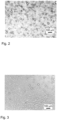
- Fig. 2 and 3 show exemplary images recorded by the video camera. Specifically, Fig.
- Fig. 2 depicts an image of a first sample of the fuel emulsion which has passed the blending unit 30 when the fuel supply system 12 is operated in a first operating mode.
- Fig. 3 depicts an image of a second sample of the fuel emulsion which has passed the blending unit 30 when the fuel supply system 12 is operated in a second operating mode.
- the second operating mode is an operating mode in which the pumps of the fuel supply system 12 are operated with more power and/or the valves of the fuel supply system 12 are operated at higher passage rates compared to the first operating mode.
- the operational mode or operational condition of the set of pumps and valves of the fuel supply system 12 in particular the input and output power of the pumps, may be varied.
- the respective flow characteristics may be varied by means of the set of pumps and valves, e.g. the supply valve controller 41 and/or the dosing pump 62.
- the fuel supply system 12 further comprises a fuel emulsion recirculation line 46 which is connected to an outlet of the fuel return line 22 of the fuel injection system 16 and which opens into a recirculation inlet 72 of the buffer tube 32.
- the fuel supply system 12 provides or comprises a fuel emulsion circuit 48 configured for circulating the fuel emulsion through the fuel supply system 12 and the fuel injection system 16. In this way, unspent fuel emulsion, i.e. fuel emulsion which is guided through the fuel injection system 16 but not injected, can be redirected into the buffer tube 32.
- the fuel emulsion circuit 48 is constituted by, i.e. comprises, the fuel emulsion recirculation line 48 configured to receive unspent fuel emulsion form the fuel injection system 16 and the fuel emulsion supply line 44 configured for supplying the fuel emulsion to the fuel injection system 16.
- the primary fuel supply line 34 may also serve as a fuel emulsion supply line 44.
- the engine may be operated only on the primary fuel such that the primary fuel supply line 34 only supplies the primary fuel.
- the buffer tube may contain only or predominantly the primary fuel.
- the starting phase may be followed by a mixing phase in which the secondary fuel is mixed with the primary fuel by means of the blending unit 30 as set forth above.
- the primary fuel can then be replaced by the fuel emulsion within the buffer tube 32 by means of the fuel emulsion recirculation line 46 and the fuel emulsion circuit 48.
- the primary fuel supply line 34 then serves in the form of the fuel emulsion supply line 44 to supply the fuel emulsion.
- the mixing phase may be followed by a shutdown phase in which the feeding of the secondary fuel can be reduced until only or predominantly the primary fuel is supplied to the blending unit 30 and to the engine 14 accordingly.
- the fuel emulsion recirculation line 46 and thus also the buffer tube 32, can contain only or predominantly the primary fuel.
- the fuel supply system 12 optionally comprises one or more heat exchanger units 50, in particular cooler units, which may be installed in the fuel emulsion recirculation line 48 and/or the fuel emulsion supply line 44.
- the heat exchanger unit 50 may comprise one heat exchanger or a plurality of heat exchangers connected in series.
- the heat exchanger units 50 may be installed in the fuel emulsion recirculation line 48 and/or the fuel emulsion supply line 44 such that the fuel emulsion may be selectively guided through or bypass the heat exchanger unit 50 as indicated in Fig. 1a by bypass lines and corresponding valves.
- one or more sensor units 56 may be provided.
- four sensor units 56a-d are installed at different positions as depicted in Fig. 1a or Fig. 1b , respectively. It is noted that each sensor unit 56a-d is optional and that more than one sensor unit 56a-d may be provided.
- the sensor units 56a-d may be configured to determine at least one physical or chemical characteristic of the fuel emulsion. Specifically the physical or chemical characteristic may be indicative of or may be at least one of density, viscosity, dielectricity, temperature, pressure, flow velocity, mass fraction and volume fraction of the secondary fuel.
- a first sensor unit 56a may be installed in the fuel injection system 16 between the filter 26 and the injection pumps 20.
- a second sensor unit 56b may be arranged downstream of the blending unit 30 and upstream of the fuel injection system 16 or the filter 26.
- a third sensor unit 56c may be installed in the fuel emulsion supply line 44, in particular downstream of the buffer tube 32 and upstream of circulation pumps 52 (see Fig. 1b ).
- a fourth sensor unit 56d may be installed in the fuel emulsion recirculation line 46, in particular upstream of the buffer tube 32 and downstream of the heat exchanger unit 50.
- a fifth sensor unit 58 may be installed in the primary fuel supply line 34, as depicted in Fig. 1b .
- the fifth sensor unit 58 may be configured to determine at least one characteristic being indicative of or being a volume flow, mass flow, flow velocity, pressure and temperature of the primary fuel flowing therethrough.
- a sixth sensor unit 60 may be installed in the secondary fuel supply line 38, as depicted in Fig. 1b .
- the sixth sensor unit 60 may be configured to determine at least one characteristic being indicative of or being a volume flow, mass flow, flow velocity, pressure and temperature of the primary fuel flowing therethrough.
- the control unit 54 may be configured to control operation of the blending unit 30, in particular by controlling the set of pumps and valves as set forth above, e.g. the dosing pump 62 and/or the supply valve controller 41, in dependence on the at least one characteristic determined by one or more of the first to sixth sensor unit 56a-d, 58, 60. Further, the control unit 54 may be configured to control, in dependence on the characteristic determined by the first to sixth sensor unit 56a-d, 58, 60, the supply of the primary fuel via the primary fuel supply line 34 and the supply of the secondary fuel via the secondary fuel supply line 38. For doing so, the control unit 54 may be configured to control operation of the primary fuel supply valve 36 and the secondary fuel supply valve 40. In this way, the control unit 54 is enabled to set a desired composition of the fuel emulsion, particularly a desired volume or mass fraction of the secondary fuel in the fuel emulsion.
- the fuel supply comprises two blending units 30a,b. Accordingly, a first blending unit 30a is provided to direct the emulsion fuel into a buffer tube 32.
- the first blending unit 30a is installed upstream of the buffer tube 32, that is upstream of an outlet of the buffer tube 32.
- the first blending unit 30a comprises a first inlet, in particular in the form of the first T-inlet 66, configured to receive the primary fuel, in particular exclusively the primary fuel.
- the first inlet is fluid-communicatively connected to the primary fuel supply line 34 via which the primary fuel, in particular exclusively the primary fuel, is selectively supplied to the first blending unit 30a.
- the primary fuel supply line 34 may connect the primary fuel storage tank (not shown) to the first blending unit 30a.
- the primary fuel storage tank may be configured to store the primary fuel.
- the storage capacity of the primary fuel storage tank may be greater, in particular substantially greater, than the storage capacity or volume of the buffer tube 32.
- the primary fuel supply valve 36 is installed in the primary fuel supply line 34.
- the first blending unit 30a comprises a second inlet, in particular in the form of the second T-inlet 68, configured to receive the secondary fuel, in particular exclusively the secondary fuel.
- the second inlet is fluid-communicatively connected to the secondary fuel supply line 38 via which the secondary fuel, in particular exclusively the secondary fuel, is selectively supplied to the first blending unit 30a.
- the secondary fuel supply line 38 may connect the secondary fuel storage tank (not shown) to the first blending unit 30a.
- the secondary fuel storage tank may be configured to store the secondary fuel.
- the storage capacity of the he secondary fuel storage tank may be greater, in particular substantially greater, than the storage capacity of the buffer tube 32.
- the secondary fuel supply valve 40 is installed in the secondary fuel supply line 38.
- the first blending unit 30a comprises an outlet configured to direct the fuel emulsion generated by the first blending 30a unit into the buffer tube 32.
- the outlet is connected, in particular directly connected to an input of the buffer tube 32 via the connecting line 42.
- the fuel supply system 12 further comprises a second blending unit 30b which is installed downstream of the buffer tube 32.
- the second blending unit 30b is optional.
- the fuel supply system 12 comprises a fuel emulsion supply line 44 which connects the buffer tube 32, in particular an outlet of the buffer tube 32, to the fuel receiving line 18 of the fuel injection system 16.
- the second blending unit 30b is installed in the fuel emulsion supply line 44.
- the second blending unit 30b comprises one single inlet via which the emulsion fuel discharge from the buffer tube 32 is received.
- the second blending unit 30b comprises the inlet for receiving the fuel emulsion from the buffer tube 32 and the outlet configured to direct the fuel emulsion after being processed in the second blending unit 30b to the fuel injection system 16 of the engine 14.
- the fuel emulsion may be blended in two stages.
- the emulsion fuel is guided through the second blending unit 30b and thereby processed to provide finer dispersions in the fuel emulsion.
- an outlet of the second blending unit 30b is connected to an inlet of the fuel injection system 16 via the fuel emulsion supply line 44.
- fuel emulsion guided through the fuel emulsion supply line 44 is directed to the fuel receiving line 18 of the fuel injection system 16.
- the fuel supply system 12 comprises two circulation pumps 52 and a heat exchanger unit 50 installed in the fuel emulsion supply line 44, in particular downstream of the buffer tube 32 and upstream of the second blending unit 30b.
- the circulation pumps 52 are configured to selectively subject the fuel emulsion flowing therethrough to a pressure difference to set a desired flow, for example having a desired flow velocity, through the fuel emulsion circuit 48. It should be noted that, while two circulation pumps 52 disposed in parallel are provided in the shown configuration, in other configurations, more or less than two circulation pumps may be provided.
- the primary and the secondary fuel may be supplied to two separate inlets of the buffer tube 32.
- the blending unit may be installed downstream of the buffer tube and can have one single inlet connected to an outlet of the buffer tube 32.
- the primary and the secondary fuel may be pre-mixed within the buffer tube, e.g. by means of a deflecting element 74 and/or an agitator 76 as depicted in Figures 4a ,b.
- the static mixer 31 of the blending unit 30 may contribute to improving the blending of the already pre-mixed fuel emulsion.
- the design of the buffer tube 32 may be adapted such that the blending quality of the fuel emulsion within the buffer tube 32 can be further improved by providing further configurations which are described in the following.
- the buffer tube volume is specified such that a buffer displacement rate does not exceed 7 minutes, particularly 5 minutes, more particularly 3 minutes, while the engine is being operated at full load, wherein the buffer displacement rate is a function at least of the engine load, the buffer tube volume and a set of fuel supply conduit characteristics including flow velocity and cross-section.
- the size of the buffer tube 32 is limited such that the buffer tube volume substantially corresponds to an amount of fuel sufficient to maintain the engine operating for 7, 5 or 3 minutes at full load.
- a 5 MW engine may have a buffer tube volume of about 60-120 liter in order to ensure sufficient flow within the buffer tube 32.
- the buffer tube 32 may have a recirculation inlet 72 configured for receiving the unspent fuel from the fuel emulsion recirculation line, wherein the buffer tube 32 may have at least one deflection element 74, in particular a deflection conduit 74 and/or a turbulator and/or a baffle, configured for deflecting the unspent fuel discharged from the recirculation inlet 72.
- the flow characteristics within the buffer tube 32 may be further improved, e.g. by means of turbulences, in order to prevent segregation of the fuel emulsion.
- the buffer tube may comprise an agitator 76 configured for agitating the fluid within the buffer tube 32, e.g. by means of rotating paddles. In this way, the flow characteristics within the buffer tube 32 may be further improved.
- a fuel supply system of an internal combustion engine in particular of a marine diesel engine, may be provided for supplying a fuel emulsion to a fuel injection system of the engine, including at least one blending unit comprising a static mixer and configured to blend a primary fuel and a secondary fuel to provide the fuel emulsion prior to being supplied to the fuel injection system.
- the primary fuel may be fuel oil or diesel fuel.
- the secondary fuel may be at least one of methanol, ammonia, liquid natural gas and hydrogen.
- the secondary fuel may be methanol.
- the fuel emulsion provided by the fuel supply system, in particular by the blending unit, may have a selectable volume fraction of up to 80 % of the secondary fuel, for example 70 % or substantially 70% of the secondary fuel.
- the static mixer may comprise a turbulator arrangement, in particular comprising at least two grids of joint metal bars.
- the blending unit may be configured to provide or process the fuel emulsion such that, upon being discharged from the blending unit, the fuel emulsion has a mean droplet size of dispersed phase which is smaller than 100 ⁇ m.
- the fuel supply system may comprise a primary fuel supply line for selectively supplying the primary fuel into the blending unit, in particular into a first inlet of the blending unit, and a secondary fuel supply line for selectively supplying the secondary fuel into the blending unit, in particular into a second inlet of the blending unit.
- the blending unit may have a T-piece comprising a first T-inlet and a second T-inlet of the blending unit on its upstream side and being fluidly connected to the static mixer on its downstream side.
- the fuel supply system may comprise a buffer tube configured for buffering a fuel medium, in particular the primary or secondary fuel or the fuel emulsion, wherein the blending unit is installed upstream or downstream of the buffer tube.
- the fuel supply system may comprise a first blending unit installed upstream of the buffer tube and a second blending unit installed downstream of the buffer tube.
- the first blending unit comprises a first inlet configured to receive the primary fuel, a second inlet configured to receive the secondary fuel and an outlet configured to direct the fuel emulsion generated by the first blending unit into the buffer tube.
- the second blending unit comprises an inlet for receiving the fuel emulsion from the buffer tube and an outlet configured to direct the fuel emulsion after being processed in the second blending unit to the fuel injection system of the engine.
- the fuel supply system may further comprise a fuel emulsion circuit configured for circulating the fuel emulsion through the fuel supply system and optionally the fuel injection system.
- the fuel emulsion circuit may comprise a fuel emulsion recirculation line configured to receive unspent fuel emulsion form the fuel injection system and a fuel emulsion supply line configured for supplying the fuel emulsion to the fuel injection system.
- the buffer tube may have a recirculation inlet configured for receiving the unspent fuel from the fuel emulsion recirculation line, wherein the buffer tube may have at least one deflection element, in particular a deflection conduit and/or a turbulator and/or a baffle, configured for deflecting the unspent fuel discharged from the recirculation inlet.
- the buffer tube may have at least one deflection element, in particular a deflection conduit and/or a turbulator and/or a baffle, configured for deflecting the unspent fuel discharged from the recirculation inlet.
- the fuel supply system may further comprise at least one sensor unit configured to determine at least one physical or chemical characteristic of the fuel emulsion, in particular downstream of the at least one blending unit, and a control unit configured to control the operation of the pumps and/or valves of the fuel supply system in dependence on the characteristic determined by the at least one sensor unit.
- the characteristic of the fuel emulsion may be indicative of or may be at least one of: density, viscosity, dielectricity, temperature, pressure, flow velocity, mass fraction of the secondary fuel and volume fraction of the secondary fuel.
- the control unit may be configured to control, in dependence on the characteristic determined by the sensor unit, at least one of a supply of the primary fuel to the blending unit and a supply of the secondary fuel to the blending unit.
- the buffer tube volume may be specified such that a buffer displacement rate does not exceed 7 minutes, particularly 5 minutes, more particularly 3 minutes, while the engine is being operated at full load, wherein the buffer displacement rate may be a function at least of the engine load, the buffer tube volume and a set of fuel supply conduit characteristics including flow velocity and cross-section.
- the buffer tube may comprise an agitator configured for agitating a fluid within the buffer tube.
- a fuel supply system of an internal combustion engine is suggested.
- the fuel supply system as mentioned above is applicable in any suitable internal combustion engine.
- the suggested fuel supply system unit may replace conventional fuel supply systems and may serve as a replacement or retrofit part.
Landscapes
- Engineering & Computer Science (AREA)
- Chemical & Material Sciences (AREA)
- Combustion & Propulsion (AREA)
- Mechanical Engineering (AREA)
- General Engineering & Computer Science (AREA)
- Oil, Petroleum & Natural Gas (AREA)
- Chemical Kinetics & Catalysis (AREA)
- General Chemical & Material Sciences (AREA)
- Output Control And Ontrol Of Special Type Engine (AREA)
- Fuel-Injection Apparatus (AREA)
Abstract
The present invention refers to a fuel supply system (12) of an internal combustion engine (14), in particular of a marine diesel engine, for supplying a fuel emulsion to a fuel injection system (16) of the engine (14). The fuel supply system (12) includes at least one blending unit (30) comprising a static mixer (31) and configured to blend a primary fuel and a secondary fuel to provide the fuel emulsion prior to being supplied to the fuel injection system (16).
Description
- The present invention refers to a fuel supply system for supplying a fuel emulsion to a fuel injection system of an internal combustion engine, in particular of a marine engine.
- Due to environmental regulations, marine vessels, such as ferries, cruise ships or cargo ships, are subjected to strict restrictions regarding emissions. Recent regulations introduced by the International Maritime Organization (IMO), for example, aim on reducing greenhouse gas emissions of ships. For verifying their compliance, the IMO has introduced different measures to determine energy efficiency of ships, such as the Energy Efficiency Existing Ship Index (EEXI) and the Energy Efficiency Design Index (EEDI).
- To reduce greenhouse gas emissions and thus to fulfill regulatory requirements, it is known to operate marine engines on alternative fuels, such as liquified petroleum gas, compressed natural gas, liquid natural gas, biomethane, ethanol, methanol and hydrogen. Techniques are known according to which a primary fuel, such as diesel, of marine engines is mixed and thus combusted together with alternative fuels. For doing so, it is known to separately introduce the primary and alternative fuel into cylinders of the engine. This approach, however, requires injection mechanisms for both the primary fuel and the alternative fuel.
- According to another approach, it is known to mix the primary fuel and the alternative fuel together prior to being injected to the cylinders of the engine. However, the primary fuel and the alternative fuel may be two normally immiscible liquids which, when mixed together, form an emulsion. The phase segregation in such an emulsion may affect the combustion process in the engine and may thus result in unfavorable operating conditions.
- Starting from the prior art, it is an objective to provide an improved fuel supply system which in particular enables an internal combustion engine to efficiently run on a fuel mixture comprising two normally immiscible liquid fuels.
- This objective is solved by the subject matter of the independent claim. Preferred embodiments are set forth in the present specification, the Figures as well as the dependent claims.
- Accordingly, a fuel supply system of an internal combustion engine, in particular of a marine diesel engine, is provided. The fuel supply system is intended for supplying a fuel emulsion to a fuel injection system of the engine and, for doing so, comprises at least one blending unit comprising a static mixer and configured to blend a primary fuel and a secondary fuel to provide the fuel emulsion prior to being supplied to the fuel injection system.
- The present disclosure will be more readily appreciated by reference to the following detailed description when being considered in connection with the accompanying drawings in which:
-
Figs. 1a and1b each schematically show an embodiment of a fuel supply system of an internal combustion engine; -
Figs. 1c and 1d schematically show examples of a blending unit according to the embodiments ofFigs. 1a and1b , respectively; -
Fig. 2 shows a video-microscopy image of a sample of a fuel emulsion provided by a fuel supply system; -
Fig. 3 shows a video-microscopy image of another sample of a fuel emulsion provided by a fuel supply system; -
Figs. 4a and 4b schematically show examples of a buffer tube according to further embodiments of a fuel supply system. - In the following, the invention will be explained in more detail with reference to the accompanying Figures. In the Figures, like elements are denoted by identical reference numerals and repeated description thereof may be omitted in order to avoid redundancies.
-
Figure 1a depicts an internalcombustion engine system 10 of a vessel including afuel supply system 12 and aninternal combustion engine 14, referred to as "the engine" in the following. In the shown configuration, theengine 14 is a medium speed combustion engine provided in the form of a marine diesel engine. However, the present invention is not limited to this specific application and may be applied in different technical fields and applications, such as in internal combustion engine systems used in power plants or vehicles as a main or auxiliary engine or the like. Further, it is apparent to the skilled person that the suggestedfuel supply system 12 is not limited to be used in combination with theengine 14 of the shown configuration, but rather may be applied to any suitable internal combustion engines, such as gasoline engines. - In the shown configuration, the
engine 14 includes a plurality of cylinders and a corresponding number of piston assemblies disposed therein (not shown). Theengine 14 may include any number of cylinders which may be arranged according an "in-line" configuration, a "V-configuration", or any other known cylinder configuration. Each cylinder is provided with a combustion chamber delimited by a cylinder wall and a piston accommodated therein. During operation of theengine 14, each one of the combustion chambers is supplied with a fuel medium and intake air which are to be ignited therein so as to produce high-temperature and high-pressure gases, thereby applying forces to and thus axially move the associated pistons. In this way, chemical energy is transformed into mechanical energy. - For supplying the fuel medium into the combustion chambers, the
engine 14 comprises afuel injection system 16 configured for injecting the fuel medium, in particular a liquid fuel medium into the respective combustion chambers of theengine 14. Thefuel injection system 16 will be further specified below with reference toFig. 1a . - For supplying intake air into the combustion chambers, the engine further comprises an air intake system (not shown) comprising a plurality of air intake valves opening into the respective combustion chambers and configured for selectively directing intake air into the combustion chambers.
- Further, for expelling combustion gases from the combustion chambers, i.e. after combustion of the fuel mixture took place, the
engine 14 further comprises an exhaust gas system (not shown) comprising a plurality of exhaust gas valves configured for selectively expelling exhaust gases from the combustion chambers. - The
fuel injection system 16 comprises afuel receiving line 18 which is configured to receive a fuel medium from thefuel supply system 12. Upon receiving the fuel medium, the fuel receivingline 18 is configured to guide the received fuel medium to a plurality ofinjection pumps 20 which pressurize and inject the fuel medium into the respective combustion chambers of theengine 14. The number ofinjection pumps 20 may correspond to the number of cylinders of theengine 14. Thefuel injection pumps 20 are connected to afuel return line 22 via afuel bypass line 24 to direct unspent fuel, i.e. fuel passing theinjection pumps 20 without being injected into the combustion chambers, to thefuel supply system 12. Alternatively, instead of theinjection pumps 20, a common rail and an associated high pressure pump may be used to supply pressurized fuel medium to the combustion chambers via corresponding injectors. Thefuel injection system 16 further comprises afilter 26 installed in thefuel receiving line 18 to filter contaminants from the fuel medium supplied to thefuel injection system 16 prior to being directed to thefuel pumps 20. - The basic structure and function of such an
engine 14 and its components, in particular the air intake system, the exhaust gas system and thefuel injection system 16, are well known to a person skilled in the art and are thus not further specified. Rather, characteristics of thecombustion engine system 10, in particularly thefuel supply system 12, which are interlinked with the present invention are addressed in the following. - The
fuel supply system 12 is intended and configured for supplying a fuel emulsion to thefuel injection system 16 of theengine 14. In the context of the present disclosure, the term "fuel emulsion" refers to a fuel medium provided as a mixture of two or more liquid fuels that are normally not soluble or miscible with one another owing to liquid-liquid phase separation. - The fuel emulsion comprises or consists of a primary fuel, also referred to as primary fuel medium, and a secondary fuel, also referred to as secondary fuel medium. In the fuel emulsion, the primary fuel may constitute a continuous phase and the secondary fuel may constitute a dispersed phase, or vice versa. In other words, in the fuel emulsion, the secondary fuel may be dispersed in the continuous phase formed by the primary fuel, or vice versa. The primary fuel and the secondary fuel may be in a liquid phase, in particular when being supplied to the
fuel supply system 12. - In the shown configuration, the primary fuel is a fuel oil or diesel fuel, in particular marine diesel oil, more particularly marine diesel oil according to the standard ISO 8217. In an alternative configuration, the primary fuel may be gasoline.
- The secondary fuel may be at least one of methanol, ammonia, liquid natural gas and hydrogen. In the shown configuration, the secondary fuel comprises or is composed of methanol.
- By providing the fuel emulsion, the secondary fuel, particularly methanol, substitutes a part of the primary fuel, particularly marine diesel oil. As the combustion of the secondary fuel, i.e. methanol, generates less greenhouse gases, in particular less carbon dioxide, compared to the combustion of the primary fuel, i.e. marine diesel oil, the overall pollutant emission of the engine may be reduced when running on the fuel emulsion instead of exclusively on the primary fuel. In this way, the suggested fuel supply system enables to reduce EEIX or EEDX of the vessel being equipped with the
combustion engine system 10. - Specifically, the fuel emulsion, in particular when being supplied to the
fuel injection system 16, may comprise a volume or mass fraction of up to 80% of the secondary fuel. For example the fuel emulsion may comprise a volume fraction of the secondary fuel of substantially 70% or substantially 60% or substantially 50%. - In the context of the present invention, it has been found that, directing a fuel emulsion into combustion chambers of an engine may affect combustion properties and thus operation of the engine. This may particularly be the case when the fuel emulsion is not properly blended before being injected into the cylinders of the engine, thereby possibly leading to unstable and, among cylinders, to uneven combustion phenomena.
- The suggested
fuel supply system 12 is equipped with a blendingunit 30 comprising astatic mixer 31 and configured to blend the primary fuel and the secondary fuel to provide or generate the fuel emulsion prior to being supplied to thefuel injection system 16. In an alternative embodiment, the fuel supply system may comprise multiple blending units, e.g. two blendingunits 30a,b, in particular afirst blending unit 30a and asecond blending unit 30b as exemplarily depicted inFigure 1b . By being provided with at least one of the two blendingunits 30a,b, the suggestedfuel supply system 12 may contribute to preventing theengine 14 from being subjected to the above described undesired combustion phenomena or to counteract these combustion phenomena. - In the following, the structural and functional configuration of the blending
unit 30 comprising thestatic mixer 31 is described which may apply to any one or both of the two blendingunits 30a,b employed in thefuel supply system 12. In the context of the present disclosure, the term "static mixer" refers to a mixer for the continuous mixing of at least two fluids, which has no actuated or moving components. - Specifically, the
static mixer 31 may be provided in the form of a tubular internal that produces the desired blending and dispersion effects as the primary and secondary fuels flow around motionless mixer parts of thestatic mixer 31. Accordingly, the energy needed for provided the desired blending and dispersion is provided by means of the fluid flow which is provided by pumps already existent in a typical fuel supply system. - More specifically and with reference to
Figures 1c and 1d , the blendingunit 30 may comprise two separate inlets, in particular a first T-inlet 66 and a second T-inlet 68 connected by means of a T-piece 64, wherein the first and second T-inlet piece 64. The T-piece 64 may have a T-outlet 70 at its downstream side by means of which the T-piece 64 may be fluidly connected to thestatic mixer 31. In the context of the present disclosure, the terms "upstream" and "downstream" refer to a flow direction of the fuel emulsion through thefuel supply system 12. The structural arrangement of the T-piece 64 within the blendingunit 30 may be carried out in different manner, as depicted inFig. 1c ,d. - Specifically, the
static mixer 31 may comprise a turbulator arrangement 78, in particular comprising at least two grids of joint metal bars, indicated by the crossed lines inFig. 1a ,c,d . More specifically, the least two grids of joint metal bars may be arranged in an interlaced manner for generating a turbulent flow. In this way, the fuel emulsion can be created in an effective and efficient manner. - As set forth above, the turbulator arrangement 78 may be constructed in the form of an insert, which can be inserted in existing conduits. Specifically, the metal bars may be casted and/or may be joint by welding or brazing. In this way, the turbulator arrangement 78 may be provided in a simple and efficient manner, even in existing conduit designs. Furthermore, the turbulator arrangement 78 may comprise alternative or additional turbulator elements, such as dimples or fins.
- Accordingly, the blending
unit 30 comprising thestatic mixer 31 may be operated without moving components or external power. Thus, the blendingunit 30 may be referred to as a non-actuated or passive blending unit. In this way, the suggestedstatic mixer 31 is very robust and cost efficient. - As set forth above, the energy needed for providing the desired blending performance of the blending
unit 30 depends on the fluid flow at the inlet of the blendingunit 30 or thestatic mixer 31, respectively. - According to the embodiment shown in
Fig. 1a , thefuel supply system 12 comprises abuffer tube 32 configured for buffering a fuel medium, e.g. the primary fuel or the fuel emulsion. Further, thefuel supply system 12 has a primaryfuel supply line 34 connecting a primaryfuel storage tank 101 to thebuffer tube 32 and configured for supplying the primary fuel to thebuffer tube 32. The blendingunit 30 is installed downstream of thebuffer tube 32. - The
fuel supply system 12 further comprises adosing pump 62 connected to a secondaryfuel storage tank 102 by means of a secondaryfuel supply line 38. The dosing pump is configured for feeding a desired amount of secondary fuel to theblending unit 30, in particular to the second T-inlet 68 of the T-piece 64. The primary and secondaryfuel supply lines Fig. 1a ), e.g. a primary a primaryfuel supply valve 36 and a secondaryfuel supply valve 40 as depicted inFig. 1b , for setting a desired flow rate of the respective fluid at the inlets of the T-piece 64. Thefuel supply system 12 may further comprise asupply valve controller 41 which is configured for controlling the primaryfuel supply valve 36 and the secondaryfuel supply valve 40. - Specifically, the
fuel supply system 12 comprises acontrol unit 54 configured for controlling thesupply valve controller 41 and/or for controlling a set of pumps and valves of thefuel supply system 12 so as to set a desired output power thereof and/or to set flow characteristics thereof. In this way, a blending degree, i.e. how fine dispersion in the fuel emulsion is to be set, can be controlled. Specifically, the set of pumps and valves of thefuel supply system 12 may comprise at least one primaryfuel supply valve 36, at least one secondaryfuel supply valve 40, at least onecirculation pump 52, and/or at least onedosing pump 62. Accordingly, thecontrol unit 54 may be connected to thesupply valve controller 41 and/or to thedosing pump 62 via signaling lines, as indicated by dotted lines inFig. 1a ,b. - Accordingly, the
fuel supply system 12, in particular the blendingunit 30, is configured to provide or process the fuel emulsion, in particular to process the primary and secondary fuels, such that, upon being discharged from the blendingunit 30, the fuel emulsion has a mean droplet size of dispersed phase which is smaller than 100 µm. In other words, upon flowing through the blendingunit 30, the primary and secondary fuel are blended such that at an outlet of the blendingunit 30 the fuel emulsion has a mean droplet size of dispersed phase, in particular formed by the secondary fuel, which is smaller than 100 µm, for example which may be about 10 µm. In the context of the present invention, it has been found that, when applying the suggestedfuel supply system 12 in marine engine applications, in particular in medium speed engine systems, generating a fuel emulsion having a mean droplet size of dispersed phase which is smaller than 100 µm in thefuel supply system 12 may enable to provide favorable combustion conditions during operation of theengine 14. As to substance, emulsions in general are instable. That is, their properties change over time and due to external influences. This instability may result in an increasing mean droplet size of the dispersed phase of the fuel emulsion when being guided through thefuel supply system 12 and thefuel injection system 16. However, by providing theblending unit 30 which generates the fuel emulsion having the mean droplet size of dispersed phase which is smaller than 100 µm, it may be ensured that the property, in particular the mean droplet size of dispersed phase, of the fuel emulsion injected into the combustion chambers of theengine 14 allows for stable combustion conditions and thus of proper operation of theengine 14. - For validating proper function of the blending
unit 30, the fuel emulsion generated by the blendingunit 30 may be analyzed using video-microscopy. For doing so, a sample of the generated fuel emulsion may be removed, for example at an outlet of the blendingunit 30 or at an outlet of thefuel supply system 12. Thereafter, an optical electron microscope accompanied with a charge-coupled device video camera may be used to analyze the fuel emulsion and to determine that a mean droplet size of the dispersed phase is smaller than a predetermined value, e.g., smaller than100 µm.Fig. 2 and 3 show exemplary images recorded by the video camera. Specifically,Fig. 2 depicts an image of a first sample of the fuel emulsion which has passed theblending unit 30 when thefuel supply system 12 is operated in a first operating mode.Fig. 3 depicts an image of a second sample of the fuel emulsion which has passed theblending unit 30 when thefuel supply system 12 is operated in a second operating mode. The second operating mode is an operating mode in which the pumps of thefuel supply system 12 are operated with more power and/or the valves of thefuel supply system 12 are operated at higher passage rates compared to the first operating mode. Thus, for adapting the property of the fuel emulsion, the operational mode or operational condition of the set of pumps and valves of thefuel supply system 12, in particular the input and output power of the pumps, may be varied. Specifically, for adapting the property of the fuel emulsion, the respective flow characteristics may be varied by means of the set of pumps and valves, e.g. thesupply valve controller 41 and/or thedosing pump 62. - The
fuel supply system 12 further comprises a fuelemulsion recirculation line 46 which is connected to an outlet of thefuel return line 22 of thefuel injection system 16 and which opens into arecirculation inlet 72 of thebuffer tube 32. By such a configuration, thefuel supply system 12 provides or comprises afuel emulsion circuit 48 configured for circulating the fuel emulsion through thefuel supply system 12 and thefuel injection system 16. In this way, unspent fuel emulsion, i.e. fuel emulsion which is guided through thefuel injection system 16 but not injected, can be redirected into thebuffer tube 32. It has been found that recirculating the fuel emulsion through thefuel supply system 12 and thefuel injection system 16 may contribute to an improved stability of the fuel emulsion, i.e. may effectively counteract changes in physiochemical properties of the fuel emulsion over time. Thefuel emulsion circuit 48 is constituted by, i.e. comprises, the fuelemulsion recirculation line 48 configured to receive unspent fuel emulsion form thefuel injection system 16 and the fuelemulsion supply line 44 configured for supplying the fuel emulsion to thefuel injection system 16. - Accordingly, the primary
fuel supply line 34 may also serve as a fuelemulsion supply line 44. For example, during a starting phase of theengine 14, the engine may be operated only on the primary fuel such that the primaryfuel supply line 34 only supplies the primary fuel. Accordingly, during the starting phase the buffer tube may contain only or predominantly the primary fuel. The starting phase may be followed by a mixing phase in which the secondary fuel is mixed with the primary fuel by means of the blendingunit 30 as set forth above. The primary fuel can then be replaced by the fuel emulsion within thebuffer tube 32 by means of the fuelemulsion recirculation line 46 and thefuel emulsion circuit 48. Accordingly, the primaryfuel supply line 34 then serves in the form of the fuelemulsion supply line 44 to supply the fuel emulsion. The mixing phase may be followed by a shutdown phase in which the feeding of the secondary fuel can be reduced until only or predominantly the primary fuel is supplied to theblending unit 30 and to theengine 14 accordingly. Thus, in the shutdown phase, the fuelemulsion recirculation line 46, and thus also thebuffer tube 32, can contain only or predominantly the primary fuel. - The
fuel supply system 12 optionally comprises one or moreheat exchanger units 50, in particular cooler units, which may be installed in the fuelemulsion recirculation line 48 and/or the fuelemulsion supply line 44. Specifically, theheat exchanger unit 50 may comprise one heat exchanger or a plurality of heat exchangers connected in series. Theheat exchanger units 50 may be installed in the fuelemulsion recirculation line 48 and/or the fuelemulsion supply line 44 such that the fuel emulsion may be selectively guided through or bypass theheat exchanger unit 50 as indicated inFig. 1a by bypass lines and corresponding valves. - Optionally, one or more sensor units 56 may be provided. In the shown configuration four
sensor units 56a-d are installed at different positions as depicted inFig. 1a orFig. 1b , respectively. It is noted that eachsensor unit 56a-d is optional and that more than onesensor unit 56a-d may be provided. Thesensor units 56a-d may be configured to determine at least one physical or chemical characteristic of the fuel emulsion. Specifically the physical or chemical characteristic may be indicative of or may be at least one of density, viscosity, dielectricity, temperature, pressure, flow velocity, mass fraction and volume fraction of the secondary fuel. - A
first sensor unit 56a may be installed in thefuel injection system 16 between thefilter 26 and the injection pumps 20. Asecond sensor unit 56b may be arranged downstream of the blendingunit 30 and upstream of thefuel injection system 16 or thefilter 26. Athird sensor unit 56c may be installed in the fuelemulsion supply line 44, in particular downstream of thebuffer tube 32 and upstream of circulation pumps 52 (seeFig. 1b ). Afourth sensor unit 56d may be installed in the fuelemulsion recirculation line 46, in particular upstream of thebuffer tube 32 and downstream of theheat exchanger unit 50. - A
fifth sensor unit 58 may be installed in the primaryfuel supply line 34, as depicted inFig. 1b . Thefifth sensor unit 58 may be configured to determine at least one characteristic being indicative of or being a volume flow, mass flow, flow velocity, pressure and temperature of the primary fuel flowing therethrough. - A
sixth sensor unit 60 may be installed in the secondaryfuel supply line 38, as depicted inFig. 1b . Thesixth sensor unit 60 may be configured to determine at least one characteristic being indicative of or being a volume flow, mass flow, flow velocity, pressure and temperature of the primary fuel flowing therethrough. - The
control unit 54 may be configured to control operation of the blendingunit 30, in particular by controlling the set of pumps and valves as set forth above, e.g. thedosing pump 62 and/or thesupply valve controller 41, in dependence on the at least one characteristic determined by one or more of the first tosixth sensor unit 56a-d, 58, 60. Further, thecontrol unit 54 may be configured to control, in dependence on the characteristic determined by the first tosixth sensor unit 56a-d, 58, 60, the supply of the primary fuel via the primaryfuel supply line 34 and the supply of the secondary fuel via the secondaryfuel supply line 38. For doing so, thecontrol unit 54 may be configured to control operation of the primaryfuel supply valve 36 and the secondaryfuel supply valve 40. In this way, thecontrol unit 54 is enabled to set a desired composition of the fuel emulsion, particularly a desired volume or mass fraction of the secondary fuel in the fuel emulsion. - According to the embodiment shown in
Fig. 1b , the fuel supply comprises two blendingunits 30a,b. Accordingly, afirst blending unit 30a is provided to direct the emulsion fuel into abuffer tube 32. In other words, thefirst blending unit 30a is installed upstream of thebuffer tube 32, that is upstream of an outlet of thebuffer tube 32. - The
first blending unit 30a comprises a first inlet, in particular in the form of the first T-inlet 66, configured to receive the primary fuel, in particular exclusively the primary fuel. As such, the first inlet is fluid-communicatively connected to the primaryfuel supply line 34 via which the primary fuel, in particular exclusively the primary fuel, is selectively supplied to thefirst blending unit 30a. The primaryfuel supply line 34 may connect the primary fuel storage tank (not shown) to thefirst blending unit 30a. The primary fuel storage tank may be configured to store the primary fuel. The storage capacity of the primary fuel storage tank may be greater, in particular substantially greater, than the storage capacity or volume of thebuffer tube 32. For selectively supplying the primary fuel to thefirst blending unit 30a, the primaryfuel supply valve 36 is installed in the primaryfuel supply line 34. - Further, the
first blending unit 30a comprises a second inlet, in particular in the form of the second T-inlet 68, configured to receive the secondary fuel, in particular exclusively the secondary fuel. As such, the second inlet is fluid-communicatively connected to the secondaryfuel supply line 38 via which the secondary fuel, in particular exclusively the secondary fuel, is selectively supplied to thefirst blending unit 30a. The secondaryfuel supply line 38 may connect the secondary fuel storage tank (not shown) to thefirst blending unit 30a. The secondary fuel storage tank may be configured to store the secondary fuel. The storage capacity of the he secondary fuel storage tank may be greater, in particular substantially greater, than the storage capacity of thebuffer tube 32. For selectively supplying the secondary fuel to thefirst blending unit 30a, the secondaryfuel supply valve 40 is installed in the secondaryfuel supply line 38. - Still further, the
first blending unit 30a comprises an outlet configured to direct the fuel emulsion generated by thefirst blending 30a unit into thebuffer tube 32. The outlet is connected, in particular directly connected to an input of thebuffer tube 32 via the connectingline 42. - The
fuel supply system 12 further comprises asecond blending unit 30b which is installed downstream of thebuffer tube 32. In the shown configuration, thesecond blending unit 30b is optional. Specifically, thefuel supply system 12 comprises a fuelemulsion supply line 44 which connects thebuffer tube 32, in particular an outlet of thebuffer tube 32, to thefuel receiving line 18 of thefuel injection system 16. Thesecond blending unit 30b is installed in the fuelemulsion supply line 44. As set forth above, compared to thefirst blending unit 30a, to which the primary and secondary fuels are supplied separately via two inlets, thesecond blending unit 30b comprises one single inlet via which the emulsion fuel discharge from thebuffer tube 32 is received. In other words, thesecond blending unit 30b comprises the inlet for receiving the fuel emulsion from thebuffer tube 32 and the outlet configured to direct the fuel emulsion after being processed in thesecond blending unit 30b to thefuel injection system 16 of theengine 14. By this configuration, the fuel emulsion may be blended in two stages. The emulsion fuel is guided through thesecond blending unit 30b and thereby processed to provide finer dispersions in the fuel emulsion. In this configuration, an outlet of thesecond blending unit 30b is connected to an inlet of thefuel injection system 16 via the fuelemulsion supply line 44. Thus, fuel emulsion guided through the fuelemulsion supply line 44 is directed to thefuel receiving line 18 of thefuel injection system 16. - Further, in the shown configuration, the
fuel supply system 12 comprises two circulation pumps 52 and aheat exchanger unit 50 installed in the fuelemulsion supply line 44, in particular downstream of thebuffer tube 32 and upstream of thesecond blending unit 30b. The circulation pumps 52 are configured to selectively subject the fuel emulsion flowing therethrough to a pressure difference to set a desired flow, for example having a desired flow velocity, through thefuel emulsion circuit 48. It should be noted that, while two circulation pumps 52 disposed in parallel are provided in the shown configuration, in other configurations, more or less than two circulation pumps may be provided. - According to an alternative embodiment, the primary and the secondary fuel may be supplied to two separate inlets of the
buffer tube 32. Accordingly, the blending unit may be installed downstream of the buffer tube and can have one single inlet connected to an outlet of thebuffer tube 32. In this configuration, the primary and the secondary fuel may be pre-mixed within the buffer tube, e.g. by means of a deflectingelement 74 and/or anagitator 76 as depicted inFigures 4a ,b. In this case thestatic mixer 31 of the blendingunit 30 may contribute to improving the blending of the already pre-mixed fuel emulsion. - In the context of the present invention, it has been found that, the design of the
buffer tube 32 may be adapted such that the blending quality of the fuel emulsion within thebuffer tube 32 can be further improved by providing further configurations which are described in the following. - According to one configuration, the buffer tube volume is specified such that a buffer displacement rate does not exceed 7 minutes, particularly 5 minutes, more particularly 3 minutes, while the engine is being operated at full load, wherein the buffer displacement rate is a function at least of the engine load, the buffer tube volume and a set of fuel supply conduit characteristics including flow velocity and cross-section. In other words, the size of the
buffer tube 32 is limited such that the buffer tube volume substantially corresponds to an amount of fuel sufficient to maintain the engine operating for 7, 5 or 3 minutes at full load. In this way, due to the limited size of thebuffer tube 32, there is sufficient flow within thebuffer tube 32 at most engine operating modes to prevent significant decomposition of the fuel emulsion or segregation of the primary and secondary fuel, respectively. For example, a 5 MW engine may have a buffer tube volume of about 60-120 liter in order to ensure sufficient flow within thebuffer tube 32. - Additionally or alternatively, with reference to
Figure 4a , thebuffer tube 32 may have arecirculation inlet 72 configured for receiving the unspent fuel from the fuel emulsion recirculation line, wherein thebuffer tube 32 may have at least onedeflection element 74, in particular adeflection conduit 74 and/or a turbulator and/or a baffle, configured for deflecting the unspent fuel discharged from therecirculation inlet 72. In this way, the flow characteristics within thebuffer tube 32 may be further improved, e.g. by means of turbulences, in order to prevent segregation of the fuel emulsion. - Additionally or alternatively, with reference to
Figure 4b , the buffer tube may comprise anagitator 76 configured for agitating the fluid within thebuffer tube 32, e.g. by means of rotating paddles. In this way, the flow characteristics within thebuffer tube 32 may be further improved. - It will be obvious for a person skilled in the art that these embodiments and items only depict examples of a plurality of possibilities. Hence, the embodiments shown here should not be understood to form a limitation of these features and configurations. Any possible combination and configuration of the described features can be chosen according to the scope of the invention. This particularly applies in view of the technical features described in the following.
- A fuel supply system of an internal combustion engine, in particular of a marine diesel engine, may be provided for supplying a fuel emulsion to a fuel injection system of the engine, including at least one blending unit comprising a static mixer and configured to blend a primary fuel and a secondary fuel to provide the fuel emulsion prior to being supplied to the fuel injection system.
- The primary fuel may be fuel oil or diesel fuel. Alternatively or additionally, the secondary fuel may be at least one of methanol, ammonia, liquid natural gas and hydrogen. For example, the secondary fuel may be methanol.
- The fuel emulsion provided by the fuel supply system, in particular by the blending unit, may have a selectable volume fraction of up to 80 % of the secondary fuel, for example 70 % or substantially 70% of the secondary fuel.
- The static mixer may comprise a turbulator arrangement, in particular comprising at least two grids of joint metal bars.
- The blending unit may be configured to provide or process the fuel emulsion such that, upon being discharged from the blending unit, the fuel emulsion has a mean droplet size of dispersed phase which is smaller than 100 µm.
- Alternatively or additionally, the fuel supply system may comprise a primary fuel supply line for selectively supplying the primary fuel into the blending unit, in particular into a first inlet of the blending unit, and a secondary fuel supply line for selectively supplying the secondary fuel into the blending unit, in particular into a second inlet of the blending unit.
- Alternatively or additionally, the blending unit may have a T-piece comprising a first T-inlet and a second T-inlet of the blending unit on its upstream side and being fluidly connected to the static mixer on its downstream side.
- Alternatively or additionally, the fuel supply system may comprise a buffer tube configured for buffering a fuel medium, in particular the primary or secondary fuel or the fuel emulsion, wherein the blending unit is installed upstream or downstream of the buffer tube.
- Alternatively, the fuel supply system may comprise a first blending unit installed upstream of the buffer tube and a second blending unit installed downstream of the buffer tube. Optionally, the first blending unit comprises a first inlet configured to receive the primary fuel, a second inlet configured to receive the secondary fuel and an outlet configured to direct the fuel emulsion generated by the first blending unit into the buffer tube. Optionally, the second blending unit comprises an inlet for receiving the fuel emulsion from the buffer tube and an outlet configured to direct the fuel emulsion after being processed in the second blending unit to the fuel injection system of the engine.
- Alternatively or additionally, the fuel supply system may further comprise a fuel emulsion circuit configured for circulating the fuel emulsion through the fuel supply system and optionally the fuel injection system. The fuel emulsion circuit may comprise a fuel emulsion recirculation line configured to receive unspent fuel emulsion form the fuel injection system and a fuel emulsion supply line configured for supplying the fuel emulsion to the fuel injection system.
- In a further development, the buffer tube may have a recirculation inlet configured for receiving the unspent fuel from the fuel emulsion recirculation line, wherein the buffer tube may have at least one deflection element, in particular a deflection conduit and/or a turbulator and/or a baffle, configured for deflecting the unspent fuel discharged from the recirculation inlet.
- Alternatively or additionally, the fuel supply system may further comprise at least one sensor unit configured to determine at least one physical or chemical characteristic of the fuel emulsion, in particular downstream of the at least one blending unit, and a control unit configured to control the operation of the pumps and/or valves of the fuel supply system in dependence on the characteristic determined by the at least one sensor unit. Specifically, the characteristic of the fuel emulsion may be indicative of or may be at least one of: density, viscosity, dielectricity, temperature, pressure, flow velocity, mass fraction of the secondary fuel and volume fraction of the secondary fuel. In a further development, the control unit may be configured to control, in dependence on the characteristic determined by the sensor unit, at least one of a supply of the primary fuel to the blending unit and a supply of the secondary fuel to the blending unit.
- In a further development, the buffer tube volume may be specified such that a buffer displacement rate does not exceed 7 minutes, particularly 5 minutes, more particularly 3 minutes, while the engine is being operated at full load, wherein the buffer displacement rate may be a function at least of the engine load, the buffer tube volume and a set of fuel supply conduit characteristics including flow velocity and cross-section.
- In a further development, the buffer tube may comprise an agitator configured for agitating a fluid within the buffer tube.
- With reference to the Figures, a fuel supply system of an internal combustion engine is suggested. The fuel supply system as mentioned above is applicable in any suitable internal combustion engine. The suggested fuel supply system unit may replace conventional fuel supply systems and may serve as a replacement or retrofit part.
Claims (15)
- A fuel supply system (12) of an internal combustion engine (14), in particular of a marine diesel engine, for supplying a fuel emulsion to a fuel injection system (16) of the engine (14), including at least one blending unit (30) comprising a static mixer (31) and configured to blend a primary fuel and a secondary fuel to provide the fuel emulsion prior to being supplied to the fuel injection system (16).
- The fuel supply system according to claim 1, wherein the primary fuel is fuel oil or diesel fuel and/or wherein the secondary fuel is at least one of methanol, ammonia, liquid natural gas, and hydrogen.
- The fuel supply system according to claim 1 or 2, wherein the fuel emulsion provided by the blending unit (30) comprises a selectable volume fraction of the primary fuel and the secondary fuel of the emulsion, in particular up to 80 % of the secondary fuel.
- The fuel supply system according to any one of claims 1 to 3, wherein the static mixer (31) comprises a turbulator arrangement (78), in particular comprising at least two grids of joint metal bars.
- The fuel supply system according to any one of claims 1 to 4, wherein the blending unit (30) is configured to process the fuel emulsion such that, upon being discharged from the blending unit (30), the fuel emulsion has a mean droplet size of dispersed phase which is smaller than 100 µm.
- The fuel supply system according to any one of claims 1 to 5, further comprising a primary fuel supply line (34) for selectively supplying the primary fuel into the blending unit (30), in particular into a first inlet (66) of the blending unit (30a), and a secondary fuel supply line (38) for selectively supplying the secondary fuel into the blending unit (30), in particular into a second inlet (68) of the blending unit (30a).
- The fuel supply system according to claim 6, wherein the blending unit (30) has a T-piece (64) comprising a first T-inlet (66) and a second T-inlet (68) of the blending unit (30) on its upstream side and being fluidly connected to the static mixer (31) on its downstream side.
- The fuel supply system according to any one of claims 1 to 7, further comprising a buffer tube (32) configured for buffering a fuel medium, wherein the blending unit (30) is installed upstream or downstream of the buffer tube (32).
- The fuel supply system according to any one of claims 1 to 7, comprising a first blending unit (30a) installed upstream of a buffer tube (32) and a second blending unit (30b) installed downstream of the buffer tube (32), wherein in particular:the first blending unit (30a) comprises a first inlet (66) configured to receive the primary fuel, a second inlet (68) configured to receive the secondary fuel and an outlet (70) configured to direct the fuel emulsion generated by the first blending unit (30a) into the buffer tube (32); andthe second blending unit (30b) comprises an inlet for receiving the fuel emulsion from the buffer tube (32) and an outlet configured to direct the fuel emulsion after being processed in the second blending unit (30b) to the fuel injection system (16) of the engine (14).
- The fuel supply system according to any one of claims 1 to 9, further comprising a fuel emulsion circuit (48) configured for circulating the fuel emulsion through the fuel supply system (12) and the fuel injection system (16), wherein the fuel emulsion circuit comprises a fuel emulsion recirculation line (46) configured to receive unspent fuel emulsion from the fuel injection system (16) and a fuel emulsion supply line (44) configured for supplying the fuel emulsion to the fuel injection system (16).
- The fuel supply system according to claim 9, wherein the buffer tube (32) has a recirculation inlet (72) configured for receiving the unspent fuel from the fuel emulsion recirculation line (46),
wherein the buffer tube (32) has at least one deflection element (74), in particular a deflection conduit (74) and/or a turbulator and/or a baffle, configured for deflecting the unspent fuel discharged from the recirculation inlet (72). - The fuel supply system according to any one of claims 1 to 11, further comprising at least one sensor unit (56, 58, 60) configured to determine at least one physical or chemical characteristic of the fuel emulsion, in particular downstream of the at least one blending unit (30), and a control unit (54) configured to control the operation of the pumps and/or valves of the fuel supply system (12) in dependence on the characteristic determined by the at least one sensor unit (56, 58, 60), wherein the characteristic of the fuel emulsion in particular is indicative of or is at least one of: density, viscosity, dielectricity, temperature, pressure, flow velocity, mass fraction and volume fraction of the secondary fuel.
- The fuel supply system according to claim 12, wherein the control unit (54) is configured to control, in dependence on the characteristic determined by the sensor unit (56, 58, 60), at least one of a supply of the primary fuel to the blending unit (30) and a supply of the secondary fuel to the blending unit (30).
- The fuel supply system according to any one of claims 1 to 13, wherein the buffer tube volume is specified such that a buffer displacement rate does not exceed 7 minutes, particularly 5 minutes, more particularly 3 minutes, while the engine is being operated at full load,
wherein the buffer displacement rate is a function at least of the engine load, the buffer tube volume and a set of fuel supply conduit characteristics including flow velocity and cross-section. - The fuel supply system according to any one of claims 1 to 14, wherein the buffer tube (32) comprises an agitator (76) configured for agitating a fluid within the buffer tube (32).
Applications Claiming Priority (1)
| Application Number | Priority Date | Filing Date | Title |
|---|---|---|---|
| GB2311245.1A GB2632011A (en) | 2023-07-21 | 2023-07-21 | Fuel supply system for supplying a fuel emulsion to a fuel injection system of an engine |
Publications (1)
| Publication Number | Publication Date |
|---|---|
| EP4495412A1 true EP4495412A1 (en) | 2025-01-22 |
Family
ID=87851985
Family Applications (1)
| Application Number | Title | Priority Date | Filing Date |
|---|---|---|---|
| EP24184666.6A Pending EP4495412A1 (en) | 2023-07-21 | 2024-06-26 | Fuel supply system for supplying a fuel emulsion to a fuel injection system of an engine |
Country Status (3)
| Country | Link |
|---|---|
| EP (1) | EP4495412A1 (en) |
| DE (1) | DE202024002605U1 (en) |
| GB (1) | GB2632011A (en) |
Citations (3)
| Publication number | Priority date | Publication date | Assignee | Title |
|---|---|---|---|---|
| US4468127A (en) * | 1980-09-02 | 1984-08-28 | Vito Agosta | Process for metering and mixing liquids in arbitrary mass proportions |
| US20100288211A1 (en) * | 2009-05-18 | 2010-11-18 | Fuel Systems Design, LLC | Fuel system and method for burning liquid ammonia in engines and boilers |
| US20110259290A1 (en) * | 2010-04-26 | 2011-10-27 | Toyota Jidosha Kabushiki Kaisha | Ammonia burning internal combustion engine |
Family Cites Families (2)
| Publication number | Priority date | Publication date | Assignee | Title |
|---|---|---|---|---|
| EP1924763A2 (en) * | 2005-09-15 | 2008-05-28 | Toyota Jidosha Kabushiki Kaisha | Internal combustion engine using hydrogen |
| US11852082B2 (en) * | 2022-01-05 | 2023-12-26 | General Electric Company | Systems and methods for controlling a fuel blend for a gas turbine |
-
2023
- 2023-07-21 GB GB2311245.1A patent/GB2632011A/en active Pending
-
2024
- 2024-06-26 DE DE202024002605.1U patent/DE202024002605U1/en active Active
- 2024-06-26 EP EP24184666.6A patent/EP4495412A1/en active Pending
Patent Citations (3)
| Publication number | Priority date | Publication date | Assignee | Title |
|---|---|---|---|---|
| US4468127A (en) * | 1980-09-02 | 1984-08-28 | Vito Agosta | Process for metering and mixing liquids in arbitrary mass proportions |
| US20100288211A1 (en) * | 2009-05-18 | 2010-11-18 | Fuel Systems Design, LLC | Fuel system and method for burning liquid ammonia in engines and boilers |
| US20110259290A1 (en) * | 2010-04-26 | 2011-10-27 | Toyota Jidosha Kabushiki Kaisha | Ammonia burning internal combustion engine |
Also Published As
| Publication number | Publication date |
|---|---|
| GB202311245D0 (en) | 2023-09-06 |
| GB2632011A (en) | 2025-01-22 |
| DE202024002605U1 (en) | 2025-10-16 |
Similar Documents
| Publication | Publication Date | Title |
|---|---|---|
| KR101300044B1 (en) | A LARGE TURBOCHARGED TWO-STROKE DIESEL ENGINE WITH EXHAUST- OR COMBUSTION GAS RECIRCULATION AND METHOD FOR REDUCING NOx AND SOOT EMISSIONS | |
| KR20120091135A (en) | Homogenizing fuel enhancement system | |
| KR101837539B1 (en) | Emulsion fuel enabling system and method | |
| DK2543869T3 (en) | Engine system with device for recycling water emulsion fuel discharge | |
| CN105545533B (en) | Piston internal combustion engine and exhaust gas manifold, in particular combined exhaust gas manifold | |
| CN102947578B (en) | For the fuel system of fuel mixture injection in combustion engine | |
| CN101263296A (en) | Device for generating a diesel-water microemulsion and injecting the emulsion into a diesel engine | |
| US12601305B2 (en) | Fuel supply system for supplying a fuel emulsion to a fuel injection system of an engine | |
| US20050126513A1 (en) | On-board diesel oil and water emulsification system | |
| EP4495412A1 (en) | Fuel supply system for supplying a fuel emulsion to a fuel injection system of an engine | |
| US10583896B2 (en) | Fuel composition, ship, and automatic fuel composition-switching system | |
| US20090078232A1 (en) | Emulsion system for diesel fuel and water for an internal combustion engine | |
| EP2679798A1 (en) | Mixed fuel generation method, mixed fuel generation device and fuel supply device | |
| JP2023048094A (en) | Fuel admission nozzle | |
| KR102782177B1 (en) | Ventilation system of double pipe providing fuel gas to a dual fuel engine | |
| CN111219278B (en) | Mixing device for a fuel injection system of an internal combustion engine | |
| KR101864517B1 (en) | Water-mixture-fuel generation device | |
| CN117432534A (en) | Flushing system and method for low-flash-point fuel | |
| US20170145970A1 (en) | System including duel fuel injection engine and method of operation | |
| EP2847303A1 (en) | Method and system for water-fuel emulsions production | |
| KR102201255B1 (en) | Producing System And Method Of Urea Solution For SCR In Ship | |
| KR102164426B1 (en) | Internal combustion engine | |
| US20260002504A1 (en) | Unknow | |
| JP4130144B2 (en) | Fuel supply device for internal combustion engine | |
| EP4621207A1 (en) | Fuel supply device and engine system |
Legal Events
| Date | Code | Title | Description |
|---|---|---|---|
| PUAI | Public reference made under article 153(3) epc to a published international application that has entered the european phase |
Free format text: ORIGINAL CODE: 0009012 |
|
| STAA | Information on the status of an ep patent application or granted ep patent |
Free format text: STATUS: THE APPLICATION HAS BEEN PUBLISHED |
|
| AK | Designated contracting states |
Kind code of ref document: A1 Designated state(s): AL AT BE BG CH CY CZ DE DK EE ES FI FR GB GR HR HU IE IS IT LI LT LU LV MC ME MK MT NL NO PL PT RO RS SE SI SK SM TR |
|
| STAA | Information on the status of an ep patent application or granted ep patent |
Free format text: STATUS: REQUEST FOR EXAMINATION WAS MADE |
|
| 17P | Request for examination filed |
Effective date: 20250722 |