EP4495384B1 - Laufschaufel für eine turbine, rotoranordnung für eine turbine und turbine - Google Patents
Laufschaufel für eine turbine, rotoranordnung für eine turbine und turbine Download PDFInfo
- Publication number
- EP4495384B1 EP4495384B1 EP23186279.8A EP23186279A EP4495384B1 EP 4495384 B1 EP4495384 B1 EP 4495384B1 EP 23186279 A EP23186279 A EP 23186279A EP 4495384 B1 EP4495384 B1 EP 4495384B1
- Authority
- EP
- European Patent Office
- Prior art keywords
- tip
- wall
- trailing edge
- blade
- cavity
- Prior art date
- Legal status (The legal status is an assumption and is not a legal conclusion. Google has not performed a legal analysis and makes no representation as to the accuracy of the status listed.)
- Active
Links
Images


Classifications
-
- F—MECHANICAL ENGINEERING; LIGHTING; HEATING; WEAPONS; BLASTING
- F01—MACHINES OR ENGINES IN GENERAL; ENGINE PLANTS IN GENERAL; STEAM ENGINES
- F01D—NON-POSITIVE DISPLACEMENT MACHINES OR ENGINES, e.g. STEAM TURBINES
- F01D5/00—Blades; Blade-carrying members; Heating, heat-insulating, cooling or antivibration means on the blades or the members
- F01D5/12—Blades
- F01D5/14—Form or construction
- F01D5/141—Shape, i.e. outer, aerodynamic form
-
- F—MECHANICAL ENGINEERING; LIGHTING; HEATING; WEAPONS; BLASTING
- F01—MACHINES OR ENGINES IN GENERAL; ENGINE PLANTS IN GENERAL; STEAM ENGINES
- F01D—NON-POSITIVE DISPLACEMENT MACHINES OR ENGINES, e.g. STEAM TURBINES
- F01D5/00—Blades; Blade-carrying members; Heating, heat-insulating, cooling or antivibration means on the blades or the members
- F01D5/12—Blades
- F01D5/14—Form or construction
- F01D5/147—Construction, i.e. structural features, e.g. of weight-saving hollow blades
-
- F—MECHANICAL ENGINEERING; LIGHTING; HEATING; WEAPONS; BLASTING
- F01—MACHINES OR ENGINES IN GENERAL; ENGINE PLANTS IN GENERAL; STEAM ENGINES
- F01D—NON-POSITIVE DISPLACEMENT MACHINES OR ENGINES, e.g. STEAM TURBINES
- F01D5/00—Blades; Blade-carrying members; Heating, heat-insulating, cooling or antivibration means on the blades or the members
- F01D5/12—Blades
- F01D5/14—Form or construction
- F01D5/18—Hollow blades, i.e. blades with cooling or heating channels or cavities; Heating, heat-insulating or cooling means on blades
- F01D5/187—Convection cooling
-
- F—MECHANICAL ENGINEERING; LIGHTING; HEATING; WEAPONS; BLASTING
- F01—MACHINES OR ENGINES IN GENERAL; ENGINE PLANTS IN GENERAL; STEAM ENGINES
- F01D—NON-POSITIVE DISPLACEMENT MACHINES OR ENGINES, e.g. STEAM TURBINES
- F01D5/00—Blades; Blade-carrying members; Heating, heat-insulating, cooling or antivibration means on the blades or the members
- F01D5/12—Blades
- F01D5/14—Form or construction
- F01D5/20—Specially-shaped blade tips to seal space between tips and stator
-
- F—MECHANICAL ENGINEERING; LIGHTING; HEATING; WEAPONS; BLASTING
- F05—INDEXING SCHEMES RELATING TO ENGINES OR PUMPS IN VARIOUS SUBCLASSES OF CLASSES F01-F04
- F05D—INDEXING SCHEME FOR ASPECTS RELATING TO NON-POSITIVE-DISPLACEMENT MACHINES OR ENGINES, GAS-TURBINES OR JET-PROPULSION PLANTS
- F05D2220/00—Application
- F05D2220/30—Application in turbines
- F05D2220/31—Application in turbines in steam turbines
-
- F—MECHANICAL ENGINEERING; LIGHTING; HEATING; WEAPONS; BLASTING
- F05—INDEXING SCHEMES RELATING TO ENGINES OR PUMPS IN VARIOUS SUBCLASSES OF CLASSES F01-F04
- F05D—INDEXING SCHEME FOR ASPECTS RELATING TO NON-POSITIVE-DISPLACEMENT MACHINES OR ENGINES, GAS-TURBINES OR JET-PROPULSION PLANTS
- F05D2220/00—Application
- F05D2220/30—Application in turbines
- F05D2220/32—Application in turbines in gas turbines
-
- F—MECHANICAL ENGINEERING; LIGHTING; HEATING; WEAPONS; BLASTING
- F05—INDEXING SCHEMES RELATING TO ENGINES OR PUMPS IN VARIOUS SUBCLASSES OF CLASSES F01-F04
- F05D—INDEXING SCHEME FOR ASPECTS RELATING TO NON-POSITIVE-DISPLACEMENT MACHINES OR ENGINES, GAS-TURBINES OR JET-PROPULSION PLANTS
- F05D2240/00—Components
- F05D2240/20—Rotors
- F05D2240/30—Characteristics of rotor blades, i.e. of any element transforming dynamic fluid energy to or from rotational energy and being attached to a rotor
- F05D2240/304—Characteristics of rotor blades, i.e. of any element transforming dynamic fluid energy to or from rotational energy and being attached to a rotor related to the trailing edge of a rotor blade
-
- F—MECHANICAL ENGINEERING; LIGHTING; HEATING; WEAPONS; BLASTING
- F05—INDEXING SCHEMES RELATING TO ENGINES OR PUMPS IN VARIOUS SUBCLASSES OF CLASSES F01-F04
- F05D—INDEXING SCHEME FOR ASPECTS RELATING TO NON-POSITIVE-DISPLACEMENT MACHINES OR ENGINES, GAS-TURBINES OR JET-PROPULSION PLANTS
- F05D2240/00—Components
- F05D2240/20—Rotors
- F05D2240/30—Characteristics of rotor blades, i.e. of any element transforming dynamic fluid energy to or from rotational energy and being attached to a rotor
- F05D2240/306—Characteristics of rotor blades, i.e. of any element transforming dynamic fluid energy to or from rotational energy and being attached to a rotor related to the suction side of a rotor blade
-
- F—MECHANICAL ENGINEERING; LIGHTING; HEATING; WEAPONS; BLASTING
- F05—INDEXING SCHEMES RELATING TO ENGINES OR PUMPS IN VARIOUS SUBCLASSES OF CLASSES F01-F04
- F05D—INDEXING SCHEME FOR ASPECTS RELATING TO NON-POSITIVE-DISPLACEMENT MACHINES OR ENGINES, GAS-TURBINES OR JET-PROPULSION PLANTS
- F05D2250/00—Geometry
- F05D2250/30—Arrangement of components
- F05D2250/31—Arrangement of components according to the direction of their main axis or their axis of rotation
- F05D2250/314—Arrangement of components according to the direction of their main axis or their axis of rotation the axes being inclined in relation to each other
-
- F—MECHANICAL ENGINEERING; LIGHTING; HEATING; WEAPONS; BLASTING
- F05—INDEXING SCHEMES RELATING TO ENGINES OR PUMPS IN VARIOUS SUBCLASSES OF CLASSES F01-F04
- F05D—INDEXING SCHEME FOR ASPECTS RELATING TO NON-POSITIVE-DISPLACEMENT MACHINES OR ENGINES, GAS-TURBINES OR JET-PROPULSION PLANTS
- F05D2250/00—Geometry
- F05D2250/30—Arrangement of components
- F05D2250/32—Arrangement of components according to their shape
- F05D2250/324—Arrangement of components according to their shape divergent
Definitions
- the separator wall may extend curved in an arc shape.
- the separator wall may comprise a concave curved first surface facing the pressure side and a convex curved second surface facing the suction side.
- the arc shaped, curved course of the separator wall helps in defining the first and second cavities with a shape that narrows smoothly towards the trailing edge.
- the separator wall may extend curved such that a width of the respective first or second cavity with respect to a circumferential direction perpendicular to the radial direction and the axial direction, narrows towards the trailing edge. Thereby, leaked fluid flowing in the respective cavity is smoothly guided towards the trailing edge which reduces pressure loss and helps to further improve aerodynamic properties of the blade.
- a wall thickness of the separator wall may lie in a range between 1/4 to 1/32, in particular between 1/16 and 1/32, of a profile thickness of the airfoil.
- the profile thickness may be defined as a diameter of an incircle touching the suction side surface and the pressure side surface at an axial position of the blade where the diameter of the incircle is maximum. The profile thickness is measured at the tip of the airfoil. This range provides a good compromise for manufacturing and aerodynamic benefit.
- the separator wall over its length, has a substantially constant wall thickness.
- the squealer tip wall may comprise a first wall portion that extends in a first peripheral area of the tip surface facing the pressure side, and a second wall portion of the squealer tip wall that extends in a second peripheral area of the tip surface facing the suction side, wherein the first exit opening is formed in the first wall portion, and wherein the second exit opening is formed in the second wall portion.
- the separator wall may be connected to the second wall portion of the squealer tip wall and extend to the trailing edge of the airfoil. Connecting the separator wall to the second wall portion may help in forming the first tip cavity with a somewhat greater volume than the second cavity which is advantageous because leakage flow from the pressure side tends be greater than leakage flow from the suction side.
- the separator wall may end at the trailing edge. Thereby, the separator wall separates the flow of leaked fluid on the first side, i.e., the pressure side, of the separator wall and the flow of leaked fluid on the second side, i.e., the suction side, of the separator wall all the way to the trailing edge. This helps to further reduce the over tip leakage and reduces aerodynamic losses caused by the over tip leakage.
- a groove may be formed in a transition between the tip surface and the pressure side surface adjacent to the trailing edge, and wherein the first exit opening opens into the groove. Since the trailing edge, typically, is a highly filigree structure, the groove eases forming the first exit opening.
- cooling holes for discharging cooling fluid may be formed in the groove. Thereby, the leaked fluid can be discharged from the first tip cavity without compromising cooling of the region of the trailing edge.
- the second wall portion of the squealer tip wall may end distanced to the trailing edge, and the second exit opening may be formed as a gap between an end region of the second wall portion facing the trailing edge and an end region of the separator wall facing the trailing edge.
- the second wall portion of the squealer tip wall and the separator wall may approach each other towards the trailing edge so that a channel is defined therebetween, wherein the separator wall extends further towards the trailing edge than the second wall portion of the squealer tip wall, and the second exit opening is formed at the end of the channel defined by an end of the second wall portion of the squealer tip wall.
- a wall thickness of the second wall portion may decrease towards the trailing edge.
- the channel can be formed with a substantially constant width.
- the airfoil at the tip, may comprise a tip chord length, and a distance of the first exit opening to the trailing edge and/or a distance of the second exit opening to the trailing edge may lie in a range between 1/12 to 1/3, in particular between 1/9 and 1/4 of the tip chord length.
- the tip cord length may be a distance, measured parallel to a tangent line touching the airfoil from the pressure side, between the trailing edge and a point on the suction side surface having a greatest distance to the trailing edge. Since the pressure side surface comprises a generally concave curvature, the tangent line touches the pressure side surface close to the leading edge and close to the trailing edge. The distance of the first exit opening and/or the second exit opening to the trailing edge may be measured parallel to the tangent line.
- the first tip cavity may comprise a first depth measured in the radial direction from the tip surface in the first tip cavity to a radial end of the first wall portion
- the second tip cavity may comprise a second depth measured in the radial direction from the tip surface in the second tip cavity to a radial end of the second wall portion
- the second depth may be different from the first depth, e.g., smaller or larger than the first depth.
- it may be provided that at least one of the first and second depths varies along the axial direction.
- the second exit opening may positioned closer to the trailing edge of the respective blade than a throat defined between the suction side surface of the respective blade and a pressure side surface of a further blade positioned adjacent to the respective blade.
- the throat may be defined as a position on the suction side surface of the airfoil having shortest distance to the pressure side surface of the adjacent blade. Discharging the fluid from the second cavity on the suction side downstream of the throat further reduces pressure loss and thereby improves the aerodynamic properties of the blade.
- the turbine may be a gas turbine comprising a compressor configured to compress a working fluid, a combustor receiving compressed working fluid from the compressor and configured to burn a fuel to heat the working fluid, and a turbine part comprising at least one rotor assembly as described above, the turbine part being configured to expand the working fluid causing the rotor assembly to rotate.
- the rotor assembly may form part of the turbine.
- the compressor may suck air from the environment, and the compressed air may be used for combustion of the fuel in the combustor or burner.
- liquid fuel such as kerosene, diesel, ethanol, or similar may be used.
- gaseous fuel such as natural gas, fermentation gas, hydrogen, or similar can be used.
- an extent of an axis, a direction, or a structure "along" another axis, direction, or structure includes that said axes, directions, or structures, in particular tangents which result at a particular site of the respective structure, enclose an angle which is smaller than 45 degrees, preferably smaller than 30 degrees and in particular preferable extend parallel to each other.
- an extent of an axis, a direction, or a structure “crossways”, “across”, “cross”, or “transversal” to another axis, direction, or structure includes in particular that said axes, directions, or structures, in particular tangents which result at a particular site of the respective structure, enclose an angle which is greater or equal than 45 degrees, preferably greater or equal than 60 degrees, and in particular preferable extend perpendicular to each other.
- Fig. 1 schematically shows a gas turbine 300.
- the gas turbine 300 includes a compressor 310, a combustor 320, and a turbine 330.
- the turbine 330 and the compressor 310 may be mechanically integrated to form a rotor 350 which is rotatable about a common rotational axis A350.
- the compressor 310 of the gas turbine 300 may draw air as a working fluid from the environment and compress the drawn air.
- the compressor 310 may be realized as centrifugal compressor or an axial compressor.
- Fig. 1 exemplarily shows a multistage axial compressor which is configured for high mass flows of air.
- the axial compressor may include multiple rotor disks, each carrying a plurality of blades.
- the rotor disks (not shown in Fig. 1 ) are coupled to each other so as to be rotatable together about the rotational axis A350.
- Compressor vanes 313 are arranged downstream of the compressor blades 312.
- the compressor blades 312 compress the introduced air and deliver the compressed air to the compressor vanes 313 disposed adjacently downstream.
- the compressed air is supplied to the combustor 320 for combustion of a fuel, such as natural gas, hydrogen, diesel, kerosene, ethanol or similar. Further, a part of the compressed air is supplied as a gaseous cooling fluid to high-temperature regions of the gas turbine 300 for cooling purposes.
- the combustor 320 by use of the compressed air, burns fuel to heat the compressed air.
- the turbine vanes 335 are positioned upstream of the turbine blades 336 of the respective rotor disks 210.
- the turbine vanes 335 are fixed in a stator frame so that they do not rotate about the rotational axis and guide the flow of combustion gas coming from the combustor 320 passing through the turbine blades 336.
- the combustion gas is expanded in the turbine 330 and gas applies a force to the turbine blades 336 which causes the rotor 350 to rotate about the rotational axis A350.
- the compressor 310 may be driven by a portion of the power output from the turbine 330.
- Fig. 2 shows a rotor assembly 200 of the turbine 330.
- the rotor assembly 200 includes a rotor disk 210 and a plurality of blades 100.
- the rotor disk 210 may have the form of a ring and, at its outer circumference, includes multiple coupling interfaces 219 for coupling the blades 100 to the rotor disk 210.
- the coupling interfaces 219 may be formed by grooves.
- Fig. 2 shows grooves that have a cross-sectional shape like a firtree.
- the rotor assembly 200 includes multiple blades 100, e.g., compressor blades 312 of the compressor 310 or turbine blades 336 of the turbine 330.
- the blades 100 will be discussed in more detail below by reference to Figs. 3 to 6 .
- each blade 100 includes an airfoil 1, a platform 8, and a root 9.
- the airfoil 1 comprises a pressure side surface 1p and an opposite suction side surface 1s.
- the pressure side surface 1p defines a pressure side PS of the airfoil 1
- the suction side surface 1s defines a suction side SS of the airfoil 1.
- the pressure side surface 1p may be curved concave
- the suction side surface 1s may be curved convex.
- the airfoil 1 extends with respect to an axial direction A between a leading edge 13 and a trailing edge 14.
- the pressure side surface 1p and the suction side surface 1s meet at the trailing edge and at the leading edge 13.
- a radial direction R which is perpendicular to the axial direction A
- the airfoil 1 extends between a platform end 11 and a tip 12.
- the axial direction A may be parallel to the rotational axis A350.
- the platform 8 may be a substantially plate shaped structure having an expanse with respect to the axial direction A and with respect to a circumferential direction C.
- the circumferential direction C extends transverse to the axial direction A and to the radial direction R.
- the platform 8 is coupled to the platform end 11 of the airfoil 1 and may protrude from the airfoil 1 with respect to the circumferential direction C.
- the root 9 is connected to the platform 8, in particular, to a lower surface of the platform 8 and protrudes from the lower surface of the platform 8 along the radial direction R.
- the airfoil 1 and the root 9, with respect to the radial direction R extend at opposite sides of the platform 8.
- the root 9 may include a firtree shaped cross-section.
- the coupling interfaces 219 of the rotor disk 210 and the roots 9 of the blades 100 may have complementary cross-sections.
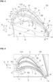
- the blade 100 further comprises squealer tip wall 2, a separator wall 4, a first exit opening 5, and a second exit opening 6.
- the blade 100 may further include an inner cavity 10.
- the squealer tip wall 2 protrudes from the tip surface 12a.
- the squealer tip wall 2 may along at least a part of the circumference of the airfoil 1.
- the squealer tip wall 2 may extend substantially along the entire circumference of the airfoil 1, as exemplarily shown in Figs. 3 and 4 .
- the squealer tip wall 2 may comprise a first wall portion 21 that extends in a first peripheral area of the tip surface 12a facing the pressure side PS, and a second wall portion 22 of the squealer tip wall 2 that extends in a second peripheral area of the tip surface 12a facing the suction side SS.
- As shown in Figs. 3 and 4 as the squealer tip wall 2 extends along at least a part of the circumference of the airfoil 1, it defines or limits a tip cavity 3.
- the tip surface 12a forms a bottom of the tip cavity 3.
- An outer lateral surface 2a of the squealer tip wall 2 may form a continuous surface with the pressure side surface 1p and suction side surface 1s, respectively. As visible in Fig. 3 , the squealer tip wall 2 protrudes, at least partially, along the radial direction from the tip surface 12a.
- at least a section of the squealer tip wall 2 protrudes over at least one of the suction side surface 1s and a pressure side surface 1p, in particular, with respect to the circumferential direction C to form a winglet structure.
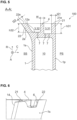
- the squealer tip wall 2 protrudes over at least one of the suction side surface 1s to form the winglet structure, as exemplarily shown in Fig. 5 .
- the separator wall 4 protrudes from the tip surface 12a and extends, at least partially, along the axial direction A.
- the separator wall 4 may extends curved in an arc shape.
- the separator wall 4 may extend from the region of the leading edge 13 to the region of the trailing edge 14.
- the separator wall 4, with a first end portion 41 may be connected to the squealer tip wall 2.
- the separator wall 4, for example may be connected to the second wall portion 22 of the squealer tip wall 2.
- the separator wall 4 may extend to, in particular, end at the trailing edge 14.
- a second end portion 42 of the separator wall 4 is positioned in the region of the trailing edge 14.
- the separator wall 4 divides the tip cavity 3 into a first tip cavity 31 and into a second tip cavity 32.
- the first tip cavity 31 lies on a first side of the separator wall 4 facing the pressure side PS.
- the first tip cavity 31, therefore, is limited by the separator wall 4 and the first wall portion 21.
- the second tip cavity 32 lies on a second side of the separator wall 4 facing the suction side SS.
- the second tip cavity 32 therefore, is limited by the separator wall 4 and the second tip wall portion 22.
- a plurality of cooling holes 7 may be formed in the tip surface 12a within the first tip cavity 31, i.e., in the part of the tip surface 12a lying between the first wall portion 21 and the separator wall 4.
- cooling holes 7 may also be formed in the tip surface 12a within the second tip cavity 32, i.e., in the part of the tip surface 12a lying between the second wall portion 22 and the separator wall 4.
- the cooling holes 7 may be connected to the inner cavity 10 of the blade 100 so that cooling fluid such a cooling air may be discharged through the cooling holes 7 on the tip surface 12a.
- the squealer tip wall 2 i.e., the first wall portion 21 and the separator wall 4 may approach each other towards the trailing edge 14. That is, a width with respect to the circumferential direction C of the first tip cavity 31 may decrease towards the trailing edge 14.
- the second wall portion 22 and the separator wall 4 may approach each other towards the trailing edge 14 at least in an end region of the second wall portion 22. That is, a width of the second tip cavity 32 with respect to the circumferential direction C may decrease towards the trailing edge 14, at least in an end region of the second wall portion 22.
- the squealer tip wall 2 and separator wall 4 helps in preventing over tip leakage flow, that is, a flow of working fluid from the pressure side PS to the suction side SS over the tip of the airfoil 1.
- the first and second exit openings 5, 6 are each formed in the squealer tip wall 2 in the area of the trailing edge 14.
- the first exit opening 5 defines a fluid passage between the first tip cavity 31 and the pressure side PS.
- the first exit opening 5 is formed in the first wall portion 21.
- the second exit opening 6 defines a fluid passage between the second tip cavity 32 and the suction side SS.
- the second exit opening 6 is formed in the second wall portion 22.
- the first and second exit openings 5, 6 are formed in the squealer tip wall 2. That is, the squealer tip wall 2 is interrupted or removed to form the respective first and second opening 5, 6.
- the first and second wall portions 21, 22 may be formed to end distanced to the trailing edge 14 so that a gap is formed between the separator wall 4 and the end region of the respective first and second wall portions 21, 22 that defines the respective opening 5, 6.
- first wall portion 21 of the squealer tip wall 2 and the separator wall 4 may approach each other towards the trailing edge 14.
- a channel may be defined between the end region of the first wall portion 21 facing the trailing edge 14 and the separator wall 4.
- the separator wall 4 extends further towards the trailing edge 14 than the first wall portion 21 of the squealer tip wall 2, as shown in Figs. 3 and 4 .
- the first exit opening 5 is formed at the end of the channel, wherein the end of the channel is defined by an end of the first wall portion 21 of the squealer tip wall 2.
- an optional groove 16 may be formed in a transition between the tip surface 12a and the pressure side surface 1p adjacent to the trailing edge 14.
- the groove 16 may be defined by a concave surface and extend between the trailing edge 14 and the end of the first wall portion 21 of the squealer tip wall 2.
- the first exit opening 5 may open into the groove 16.
- cooling holes 7 may be formed within the groove 16.
- a wall thickness of the first wall portion 21 of the squealer tip wall 2, in the end region of the first wall portion 21, may decrease to the end facing the trailing edge 14. Thereby, a channel of substantially constant width may be formed between the separator wall 4 and the end region of the first wall portion 21.
- the second exit opening 6 may also be formed at the end of a channel defined between the separator wall 4 and an end portion of the second wall portion 22 facing the trailing edge 14.
- the separator wall 4 may extend further towards the trailing edge 14 than the second wall portion 22 of the squealer tip wall 2, and the end of the second wall portion 22 defines the end of the channel.
- a wall thickness of the second wall portion 22 of the squealer tip wall 2, in the end region of the second wall portion 22, may decrease to the end facing the trailing edge 14.
- the end region of the second wall portion 22 may form a wedge as exemplarily shown in Fig. 3 .
- a channel of substantially constant width may be formed between the separator wall 4 and the end region of the second wall portion 22.
- the second wall portion 22 has a substantially constant wall thickness and only ends distanced to the trailing edge 14 as exemplarily shown in Figs. 4 and 6 .
- a convex radius may be formed on an inner edge of the end of second wall portion 22.
- the tip chord length tc1 may lie in a range between 25 mm and 250 mm, for example.
- the distance of the first exit opening 5 and/or the second exit opening 6 to the trailing edge 14 may be measured parallel to the tangent line tl.
- the second exit opening 6 may be positioned further distanced to the trailing edge 14 than the first exit opening 5.
- distance I5 may be smaller than distance I6.
- the second exit opening 6 When assembled in the rotor assembly 200, it may be provided that the second exit opening 6 is positioned closer to the trailing edge 14 of the respective blade 100 than a throat O defined between the suction side surface 1s of the respective blade 100 and a pressure side surface 1p of a further blade 100 positioned adjacent to the respective blade 100.
- Fig. 7 This situation is schematically shown in Fig. 7 where two adjacent blades 100 are shown in a top view. It should be noted that no details of the tip 12 are shown in Fig. 7 .
- the throat O may be defined as a position on the suction side surface 1s of the airfoil 1 of the respective blade 100 having shortest distance to the pressure side surface 1p of the adjacent blade 100.
- the position of the second exit opening 6 is only schematically indicated by dotted line P6. As visible, the second exit opening 6 may be positioned downstream of the throat O with respect to direction of flow from the leading edge 13 towards the trailing edge 14.
- a wall thickness t4 of the separator wall 4 may lie in a range between 1/4 to 1/32 of a profile thickness Pt of the airfoil 1.
- the wall thickness t4 may lie in a range between 1/16 to 1/32 of the profile thickness Pt.
- the profile thickness may be defined as a diameter of an incircle IC touching the suction side surface 1s and the pressure side surface 1p at an axial position of the blade where the diameter of the incircle IC is maximum.
- the profile thickness Pt is measured at the tip of the airfoil 1.
- the profile thickness may lie in a range between 11 mm and 65 mm, for example.
- the wall thickness t4 of the separator wall 4 may, for example, be in a range between 1.5 mm and 6.5 mm.
- the wall thickness of the squealer tip wall 2 may lie substantially in the same range as the wall thickness t4 of the separator wall 4.
- the wall thickness t21 of the first wall portion 21 and the wall thickness t22 of the second wall portion 22 each may lie in a range between 1/4 to 1/16 of the profile thickness Pt of the airfoil 1, e.g., in a range between 1.5 mm and 6.5 mm.
- the first tip cavity 31 may comprise a first depth h31 measured in the radial direction R from the tip surface 12a in the first tip cavity 31 to a radial end 21e of the first wall portion 21.
- the second tip cavity 32 may comprise a second depth h2 measured in the radial direction R from the tip surface 12a in the second tip cavity 32 to a radial end 22e of the second wall portion 22.
- the first depth h31 and the second depth h32 may lie in a range between 1.5 mm to 5.5 mm.
- the second depth h32 is smaller than the first depth h31.
- the invention is not limited thereto and, generally, the first and the second depth h31, h32 may be different. Further, it may be provided that the first depth h31 and/or the second depth h32 vary along the axial direction.
- the blade 100 may be manufactured, generally, in a casting process, such as conventional casting (CC), a directionally solidified (DS), or single crystal (SX) cast process. Nickel or Cobalt based high temperature alloys may be used for casting the blade 100.
- CC conventional casting
- DS directionally solidified
- SX single crystal
- the separator wall 4 may be formed by conventional manufacturing methods, e.g., by casting or machining. Alternatively, the separator wall 4 may be additively manufactured or may be formed by any combination of additive and subtractive methods. Nickel or Cobalt based high temperature alloys suitable for additive manufacturing may be used to form the separator wall 4 in an additive manufacturing process.
- the surfaces on the tip 12 of the airfoil 1, i.e., the tip surface 12a, the surfaces of the squealer tip wall 2 and the surfaces of the separator wall 4 may be coated.
- MCrAlY material or other suitable coating material may be used as bondcoat and applied, for example, by a low pressure plasma spray (LPPS), a vacuum plasma spray (VPS), or a high velocity oxy fuel (HVOF) process.
- LPPS low pressure plasma spray
- VPS vacuum plasma spray
- HVOF high velocity oxy fuel
- a topcoat may be applied.
- a single or multi-layered ceramic, e.g., YSZ may be applied by LPPS, an air plasma spray (APS), or similar.
- separator wall 4 Although only examples comprising one single separator wall 4 have been discussed above, the present invention is not limited thereto. Rather, at least one additional separator wall may be provided, e.g., to further divide the first or second tip cavity 31, 32 into sub cavities.
Landscapes
- Engineering & Computer Science (AREA)
- Mechanical Engineering (AREA)
- General Engineering & Computer Science (AREA)
- Architecture (AREA)
- Physics & Mathematics (AREA)
- Fluid Mechanics (AREA)
- Turbine Rotor Nozzle Sealing (AREA)
Claims (15)
- Schaufel (100) für eine Turbine (300), aufweisend:ein Schaufelblatt (1), das sich in Bezug auf eine radiale Richtung (R) zwischen einem Plattformende (11) und einer Spitze (12) und in Bezug auf eine axiale Richtung (A) zwischen einer Vorderkante (13) und einer Hinterkante (14) erstreckt, wobei die Spitze (12) eine Spitzenfläche (12a) aufweist und wobei sich eine Druckseitenfläche (1p) und eine Saugseitenfläche (1s) an der Vorderkante (13) und an der Hinterkante (14) treffen, wobei die Druckseitenfläche (1p) eine Druckseite (PS) des Schaufelblatts (1) definiert und die Saugseitenfläche (1s) eine Saugseite (SS) des Schaufelblatts (1) definiert;eine Anstreifspitzenwand (2), die von der Spitzenfläche (12a) vorsteht und einen Spitzenhohlraum (3) definiert;zumindest eine Trennwand (4), die von der Spitzenfläche (12a) vorsteht und den Spitzenhohlraum (3) in zumindest einen ersten Spitzenhohlraum (31), der auf einer der Druckseite (PS) zugewandten ersten Seite der Trennwand (4) liegt, und einen zweiten Spitzenhohlraum (32) unterteilt, der auf einer der Saugseite (SS) zugewandten zweiten Seite der Trennwand (4) liegt;eine erste Austrittsöffnung (5), die in der Anstreifspitzenwand (2) im Bereich der Hinterkante (14) ausgebildet ist, wobei die erste Austrittsöffnung (5) einen Fluiddurchgang zwischen dem ersten Spitzenhohlraum (31) und der Druckseite (PS) definiert; undeine zweite Austrittsöffnung (6), die in der Anstreifspitzenwand (2) im Bereich der Hinterkante (14) ausgebildet ist, wobei die zweite Austrittsöffnung (6) einen Fluiddurchgang zwischen dem zweiten Spitzenhohlraum (32) und der Saugseite (SS) definiert.
- Schaufel (100) nach Anspruch 1, wobei sich die Trennwand (4) von dem Bereich der Vorderkante (13) zu der Hinterkante (14) des Schaufelblatts (1) erstreckt.
- Schaufel (100) nach Anspruch 1 oder 2, wobei sich die Trennwand (4) bogenförmig gekrümmt erstreckt.
- Schaufel (100) nach einem der voranstehenden Ansprüche, wobei eine Wanddicke (t4) der Trennwand (4) in einem Bereich zwischen 1/4 bis 1/32 einer Profildicke (Pt) des Schaufelblatts (1) liegt.
- Schaufel (100) nach einem der voranstehenden Ansprüche, wobei die Anstreifspitzenwand (2) einen ersten Wandabschnitt (21), der sich in einem der Druckseite (PS) zugewandten ersten Umfangsbereich der Spitzenfläche (12a) erstreckt, und einen zweiten Wandabschnitt (22) der Anstreifspitzenwand (2) aufweist, der sich in einem der Saugseite (SS) zugewandten zweiten Umfangsbereich der Spitzenfläche (12a) erstreckt, wobei die erste Austrittsöffnung (5) in dem ersten Wandabschnitt (21) ausgebildet ist, und wobei die zweite Austrittsöffnung (6) in dem zweiten Wandabschnitt (22) ausgebildet ist.
- Schaufel (100) nach Anspruch 5, wobei die Trennwand (4) mit dem zweiten Wandabschnitt (22) der Anstreifspitzenwand (2) verbunden ist und sich zu der Hinterkante (14) des Schaufelblatts (1) erstreckt.
- Schaufel (100) nach Anspruch 5 oder 6, wobei der erste Wandabschnitt (21) der Anstreifspitzenwand (2) beabstandet zu der Hinterkante (14) endet, und die erste Austrittsöffnung (5) als ein Spalt zwischen einem der Hinterkante (14) zugewandten Endbereich des ersten Wandabschnitts (21) und einem der Hinterkante (14) zugewandten Endbereich der Trennwand (4) ausgebildet ist.
- Schaufel (100) nach Anspruch 7, wobei eine Nut (16) in einem Übergang zwischen der Spitzenfläche (12a) und der Druckseitenfläche (1p) benachbart zu der Hinterkante (14) ausgebildet ist, und wobei die erste Austrittsöffnung (5) in die Nut (16) mündet.
- Schaufel (100) nach einem der Ansprüche 5 bis 8, wobei der zweite Wandabschnitt (22) der Anstreifspitzenwand (2) beabstandet zu der Hinterkante (14) endet, und die zweite Austrittsöffnung (6) als ein Spalt zwischen einem der Hinterkante (14) zugewandten Endbereich des zweiten Wandabschnitts (22) und einem der Hinterkante (14) zugewandten Endbereich der Trennwand (4) ausgebildet ist.
- Schaufel (100) nach einem der voranstehenden Ansprüche, wobei das Schaufelblatt (1) an der Spitze (12) eine Spitzensehnenlänge (tc1) aufweist, und ein Abstand (I5) der ersten Austrittsöffnung (5) zu der Hinterkante (14) und/oder ein Abstand (I6) der zweiten Austrittsöffnung (6) zu der Hinterkante (14) in einem Bereich zwischen 1/12 bis 1/3, insbesondere zwischen 1/9 und 1/4 der Spitzensehnenlänge (tc1) liegt.
- Schaufel (100) nach einem der voranstehenden Ansprüche, wobei der erste Spitzenhohlraum (31) eine erste Tiefe (h31) aufweist, die in der radialen Richtung (R) von der Spitzenfläche (12a) in dem ersten Spitzenhohlraum (31) zu einem radialen Ende (21e) des ersten Wandabschnitts (21) gemessen wird, und wobei der zweite Spitzenhohlraum (32) eine zweite Tiefe (h32) aufweist, die in der radialen Richtung (R) von der Spitzenfläche (12a) in dem zweiten Spitzenhohlraum (32) zu einem radialen Ende (22e) des zweiten Wandabschnitts (22) gemessen wird, wobei sich die zweite Tiefe (h32) von der ersten Tiefe (h31) unterscheidet.
- Schaufel (100) nach einem der voranstehenden Ansprüche, wobei eine Vielzahl von Kühllöchern (7) in der Spitzenfläche (12a) in dem ersten Spitzenhohlraum (31) und/oder in dem zweiten Spitzenhohlraum (32) ausgebildet ist.
- Rotoranordnung (200) für eine Turbine (300), aufweisend:eine Rotorscheibe (210); undeine Vielzahl der Schaufeln (100) nach einem der voranstehenden Ansprüche, die mit der Rotorscheibe (210) gekoppelt sind.
- Rotoranordnung (200) nach Anspruch 13, wobei die zweite Austrittsöffnung (6) näher an der Hinterkante (14) der jeweiligen Schaufel (100) positioniert ist als ein engster Querschnitt (O), der zwischen der Saugseitenfläche (1s) der jeweiligen Schaufel (100) und einer Druckseitenfläche (1p) einer weiteren Schaufel (100) definiert ist, die benachbart zu der jeweiligen Schaufel (100) positioniert ist.
- Turbine (300), aufweisend eine Schaufel (100) nach einem der Ansprüche 1 bis 12.
Priority Applications (3)
| Application Number | Priority Date | Filing Date | Title |
|---|---|---|---|
| EP23186279.8A EP4495384B1 (de) | 2023-07-19 | 2023-07-19 | Laufschaufel für eine turbine, rotoranordnung für eine turbine und turbine |
| KR1020230123385A KR102923501B1 (ko) | 2023-07-19 | 2023-09-15 | 터빈용 블레이드, 터빈용 로터 조립체, 및 터빈 |
| US18/397,204 US12140043B1 (en) | 2023-07-19 | 2023-12-27 | Blade for a turbine, rotor assembly for a turbine, and turbine |
Applications Claiming Priority (1)
| Application Number | Priority Date | Filing Date | Title |
|---|---|---|---|
| EP23186279.8A EP4495384B1 (de) | 2023-07-19 | 2023-07-19 | Laufschaufel für eine turbine, rotoranordnung für eine turbine und turbine |
Publications (2)
| Publication Number | Publication Date |
|---|---|
| EP4495384A1 EP4495384A1 (de) | 2025-01-22 |
| EP4495384B1 true EP4495384B1 (de) | 2025-05-14 |
Family
ID=87418708
Family Applications (1)
| Application Number | Title | Priority Date | Filing Date |
|---|---|---|---|
| EP23186279.8A Active EP4495384B1 (de) | 2023-07-19 | 2023-07-19 | Laufschaufel für eine turbine, rotoranordnung für eine turbine und turbine |
Country Status (3)
| Country | Link |
|---|---|
| US (1) | US12140043B1 (de) |
| EP (1) | EP4495384B1 (de) |
| KR (1) | KR102923501B1 (de) |
Citations (1)
| Publication number | Priority date | Publication date | Assignee | Title |
|---|---|---|---|---|
| US20090068021A1 (en) * | 2007-03-08 | 2009-03-12 | Siemens Power Generation, Inc. | Thermally balanced near wall cooling for a turbine blade |
Family Cites Families (9)
| Publication number | Priority date | Publication date | Assignee | Title |
|---|---|---|---|---|
| US3635585A (en) | 1969-12-23 | 1972-01-18 | Westinghouse Electric Corp | Gas-cooled turbine blade |
| JP3453268B2 (ja) | 1997-03-04 | 2003-10-06 | 三菱重工業株式会社 | ガスタービン翼 |
| US6527514B2 (en) | 2001-06-11 | 2003-03-04 | Alstom (Switzerland) Ltd | Turbine blade with rub tolerant cooling construction |
| US8512003B2 (en) | 2006-08-21 | 2013-08-20 | General Electric Company | Tip ramp turbine blade |
| US8398370B1 (en) * | 2009-09-18 | 2013-03-19 | Florida Turbine Technologies, Inc. | Turbine blade with multi-impingement cooling |
| FR3024749B1 (fr) * | 2014-08-05 | 2016-07-22 | Snecma | Baignoire de sommet d'aubes d'une turbine de turbomachine |
| US10329922B2 (en) * | 2016-02-09 | 2019-06-25 | General Electric Company | Gas turbine engine airfoil |
| US11761339B2 (en) * | 2020-05-20 | 2023-09-19 | Siemens Energy Global GmbH & Co. KG | Turbine blade |
| EP4001591B1 (de) * | 2020-11-13 | 2024-07-24 | Doosan Enerbility Co., Ltd. | Kühlung der schaufelhinterkantenspitze einer gasturbinenschaufel |
-
2023
- 2023-07-19 EP EP23186279.8A patent/EP4495384B1/de active Active
- 2023-09-15 KR KR1020230123385A patent/KR102923501B1/ko active Active
- 2023-12-27 US US18/397,204 patent/US12140043B1/en active Active
Patent Citations (1)
| Publication number | Priority date | Publication date | Assignee | Title |
|---|---|---|---|---|
| US20090068021A1 (en) * | 2007-03-08 | 2009-03-12 | Siemens Power Generation, Inc. | Thermally balanced near wall cooling for a turbine blade |
Also Published As
| Publication number | Publication date |
|---|---|
| KR102923501B1 (ko) | 2026-02-06 |
| KR20250015650A (ko) | 2025-02-03 |
| US12140043B1 (en) | 2024-11-12 |
| EP4495384A1 (de) | 2025-01-22 |
Similar Documents
| Publication | Publication Date | Title |
|---|---|---|
| EP1126133A2 (de) | Kompressormantel mit Einschnürung | |
| CN101131097B (zh) | 叶片顶部级联挡板翼型 | |
| JP5909057B2 (ja) | 輪郭形成バンドを有するタービンノズル | |
| JP5711741B2 (ja) | 二次元プラットフォームタービンブレード | |
| CN107035422B (zh) | 带中跨护罩的涡轮转子叶片 | |
| US20140294562A1 (en) | Strut for a gas turbine engine | |
| JPH10502150A (ja) | 回転機械の圧縮領域のための流れ配向アッセンブリ | |
| CN107448300A (zh) | 用于涡轮发动机的翼型件 | |
| US20260085640A1 (en) | Devices and methods for guiding bleed air in a turbofan engine | |
| US20220034230A1 (en) | Film cooling structure and turbine blade for gas turbine engine | |
| CN110805473A (zh) | 涡轮机冷却沟槽 | |
| KR20220040981A (ko) | 가스 터빈 블레이드의 스퀄러 팁의 냉각 기술 | |
| EP4495384B1 (de) | Laufschaufel für eine turbine, rotoranordnung für eine turbine und turbine | |
| CN111373121B (zh) | 具有末端沟槽的涡轮机叶片 | |
| US20240376825A1 (en) | Flow body for a gas turbine, gas turbine, method for manufacturing a flow body for a gas turbine, and method for repairing a flow body of a gas turbine | |
| US12270317B2 (en) | Airfoils for gas turbine engines | |
| US20230258089A1 (en) | Turbine blade neck pocket | |
| CN116201605A (zh) | 用于涡轮发动机中的叶片的翼型轮廓 | |
| US12366170B2 (en) | Flow body for a gas turbine, gas turbine, method for manufacturing a flow body for a gas turbine, and method for repairing a flow body of a gas turbine | |
| EP4435230B1 (de) | Laufschaufel oder leitschaufel für eine gas turbine, turbinenlaufschaufelanordnung und gasturbine | |
| US12234743B2 (en) | Method for manufacturing a blade for a gas turbine, turbine blade and gas turbine | |
| EP4455450A1 (de) | Verfahren zur herstellung einer schaufel für eine gasturbine, schaufel für eine gasturbine und gasturbine | |
| CN119855974A (zh) | 用于附接到燃气涡轮发动机的定子护罩的导向轮叶、燃气涡轮发动机定子组件和燃气涡轮发动机 | |
| WO2019105742A1 (en) | Internally-cooled turbomachine component |
Legal Events
| Date | Code | Title | Description |
|---|---|---|---|
| PUAI | Public reference made under article 153(3) epc to a published international application that has entered the european phase |
Free format text: ORIGINAL CODE: 0009012 |
|
| STAA | Information on the status of an ep patent application or granted ep patent |
Free format text: STATUS: REQUEST FOR EXAMINATION WAS MADE |
|
| 17P | Request for examination filed |
Effective date: 20230719 |
|
| AK | Designated contracting states |
Kind code of ref document: A1 Designated state(s): AL AT BE BG CH CY CZ DE DK EE ES FI FR GB GR HR HU IE IS IT LI LT LU LV MC ME MK MT NL NO PL PT RO RS SE SI SK SM TR |
|
| GRAP | Despatch of communication of intention to grant a patent |
Free format text: ORIGINAL CODE: EPIDOSNIGR1 |
|
| STAA | Information on the status of an ep patent application or granted ep patent |
Free format text: STATUS: GRANT OF PATENT IS INTENDED |
|
| INTG | Intention to grant announced |
Effective date: 20250207 |
|
| GRAS | Grant fee paid |
Free format text: ORIGINAL CODE: EPIDOSNIGR3 |
|
| GRAA | (expected) grant |
Free format text: ORIGINAL CODE: 0009210 |
|
| STAA | Information on the status of an ep patent application or granted ep patent |
Free format text: STATUS: THE PATENT HAS BEEN GRANTED |
|
| AK | Designated contracting states |
Kind code of ref document: B1 Designated state(s): AL AT BE BG CH CY CZ DE DK EE ES FI FR GB GR HR HU IE IS IT LI LT LU LV MC ME MK MT NL NO PL PT RO RS SE SI SK SM TR |
|
| REG | Reference to a national code |
Ref country code: GB Ref legal event code: FG4D |
|
| REG | Reference to a national code |
Ref country code: CH Ref legal event code: EP |
|
| REG | Reference to a national code |
Ref country code: DE Ref legal event code: R096 Ref document number: 602023003454 Country of ref document: DE |
|
| REG | Reference to a national code |
Ref country code: IE Ref legal event code: FG4D |
|
| REG | Reference to a national code |
Ref country code: NL Ref legal event code: MP Effective date: 20250514 |
|
| PG25 | Lapsed in a contracting state [announced via postgrant information from national office to epo] |
Ref country code: FI Free format text: LAPSE BECAUSE OF FAILURE TO SUBMIT A TRANSLATION OF THE DESCRIPTION OR TO PAY THE FEE WITHIN THE PRESCRIBED TIME-LIMIT Effective date: 20250514 Ref country code: PT Free format text: LAPSE BECAUSE OF FAILURE TO SUBMIT A TRANSLATION OF THE DESCRIPTION OR TO PAY THE FEE WITHIN THE PRESCRIBED TIME-LIMIT Effective date: 20250915 Ref country code: ES Free format text: LAPSE BECAUSE OF FAILURE TO SUBMIT A TRANSLATION OF THE DESCRIPTION OR TO PAY THE FEE WITHIN THE PRESCRIBED TIME-LIMIT Effective date: 20250514 |
|
| PGFP | Annual fee paid to national office [announced via postgrant information from national office to epo] |
Ref country code: DE Payment date: 20250709 Year of fee payment: 3 |
|
| REG | Reference to a national code |
Ref country code: LT Ref legal event code: MG9D |
|
| PG25 | Lapsed in a contracting state [announced via postgrant information from national office to epo] |
Ref country code: GR Free format text: LAPSE BECAUSE OF FAILURE TO SUBMIT A TRANSLATION OF THE DESCRIPTION OR TO PAY THE FEE WITHIN THE PRESCRIBED TIME-LIMIT Effective date: 20250815 Ref country code: NO Free format text: LAPSE BECAUSE OF FAILURE TO SUBMIT A TRANSLATION OF THE DESCRIPTION OR TO PAY THE FEE WITHIN THE PRESCRIBED TIME-LIMIT Effective date: 20250814 |
|
| PG25 | Lapsed in a contracting state [announced via postgrant information from national office to epo] |
Ref country code: PL Free format text: LAPSE BECAUSE OF FAILURE TO SUBMIT A TRANSLATION OF THE DESCRIPTION OR TO PAY THE FEE WITHIN THE PRESCRIBED TIME-LIMIT Effective date: 20250514 Ref country code: NL Free format text: LAPSE BECAUSE OF FAILURE TO SUBMIT A TRANSLATION OF THE DESCRIPTION OR TO PAY THE FEE WITHIN THE PRESCRIBED TIME-LIMIT Effective date: 20250514 |
|
| PGFP | Annual fee paid to national office [announced via postgrant information from national office to epo] |
Ref country code: IT Payment date: 20250731 Year of fee payment: 3 |
|
| REG | Reference to a national code |
Ref country code: AT Ref legal event code: MK05 Ref document number: 1794913 Country of ref document: AT Kind code of ref document: T Effective date: 20250514 |
|
| PG25 | Lapsed in a contracting state [announced via postgrant information from national office to epo] |
Ref country code: BG Free format text: LAPSE BECAUSE OF FAILURE TO SUBMIT A TRANSLATION OF THE DESCRIPTION OR TO PAY THE FEE WITHIN THE PRESCRIBED TIME-LIMIT Effective date: 20250514 |
|
| PG25 | Lapsed in a contracting state [announced via postgrant information from national office to epo] |
Ref country code: HR Free format text: LAPSE BECAUSE OF FAILURE TO SUBMIT A TRANSLATION OF THE DESCRIPTION OR TO PAY THE FEE WITHIN THE PRESCRIBED TIME-LIMIT Effective date: 20250514 |
|
| PG25 | Lapsed in a contracting state [announced via postgrant information from national office to epo] |
Ref country code: AT Free format text: LAPSE BECAUSE OF FAILURE TO SUBMIT A TRANSLATION OF THE DESCRIPTION OR TO PAY THE FEE WITHIN THE PRESCRIBED TIME-LIMIT Effective date: 20250514 |
|
| PG25 | Lapsed in a contracting state [announced via postgrant information from national office to epo] |
Ref country code: RS Free format text: LAPSE BECAUSE OF FAILURE TO SUBMIT A TRANSLATION OF THE DESCRIPTION OR TO PAY THE FEE WITHIN THE PRESCRIBED TIME-LIMIT Effective date: 20250814 |
|
| PG25 | Lapsed in a contracting state [announced via postgrant information from national office to epo] |
Ref country code: IS Free format text: LAPSE BECAUSE OF FAILURE TO SUBMIT A TRANSLATION OF THE DESCRIPTION OR TO PAY THE FEE WITHIN THE PRESCRIBED TIME-LIMIT Effective date: 20250914 |
|
| PG25 | Lapsed in a contracting state [announced via postgrant information from national office to epo] |
Ref country code: LV Free format text: LAPSE BECAUSE OF FAILURE TO SUBMIT A TRANSLATION OF THE DESCRIPTION OR TO PAY THE FEE WITHIN THE PRESCRIBED TIME-LIMIT Effective date: 20250514 |
|
| PG25 | Lapsed in a contracting state [announced via postgrant information from national office to epo] |
Ref country code: DK Free format text: LAPSE BECAUSE OF FAILURE TO SUBMIT A TRANSLATION OF THE DESCRIPTION OR TO PAY THE FEE WITHIN THE PRESCRIBED TIME-LIMIT Effective date: 20250514 Ref country code: SM Free format text: LAPSE BECAUSE OF FAILURE TO SUBMIT A TRANSLATION OF THE DESCRIPTION OR TO PAY THE FEE WITHIN THE PRESCRIBED TIME-LIMIT Effective date: 20250514 |
|
| PG25 | Lapsed in a contracting state [announced via postgrant information from national office to epo] |
Ref country code: CZ Free format text: LAPSE BECAUSE OF FAILURE TO SUBMIT A TRANSLATION OF THE DESCRIPTION OR TO PAY THE FEE WITHIN THE PRESCRIBED TIME-LIMIT Effective date: 20250514 |
|
| PG25 | Lapsed in a contracting state [announced via postgrant information from national office to epo] |
Ref country code: EE Free format text: LAPSE BECAUSE OF FAILURE TO SUBMIT A TRANSLATION OF THE DESCRIPTION OR TO PAY THE FEE WITHIN THE PRESCRIBED TIME-LIMIT Effective date: 20250514 |
|
| PG25 | Lapsed in a contracting state [announced via postgrant information from national office to epo] |
Ref country code: SK Free format text: LAPSE BECAUSE OF FAILURE TO SUBMIT A TRANSLATION OF THE DESCRIPTION OR TO PAY THE FEE WITHIN THE PRESCRIBED TIME-LIMIT Effective date: 20250514 |
|
| REG | Reference to a national code |
Ref country code: DE Ref legal event code: R097 Ref document number: 602023003454 Country of ref document: DE |
|
| PG25 | Lapsed in a contracting state [announced via postgrant information from national office to epo] |
Ref country code: RO Free format text: LAPSE BECAUSE OF FAILURE TO SUBMIT A TRANSLATION OF THE DESCRIPTION OR TO PAY THE FEE WITHIN THE PRESCRIBED TIME-LIMIT Effective date: 20250514 Ref country code: LU Free format text: LAPSE BECAUSE OF NON-PAYMENT OF DUE FEES Effective date: 20250719 |
|
| PLBE | No opposition filed within time limit |
Free format text: ORIGINAL CODE: 0009261 |
|
| STAA | Information on the status of an ep patent application or granted ep patent |
Free format text: STATUS: NO OPPOSITION FILED WITHIN TIME LIMIT |
|
| REG | Reference to a national code |
Ref country code: CH Ref legal event code: L10 Free format text: ST27 STATUS EVENT CODE: U-0-0-L10-L00 (AS PROVIDED BY THE NATIONAL OFFICE) Effective date: 20260325 |
|
| REG | Reference to a national code |
Ref country code: BE Ref legal event code: MM Effective date: 20250731 |
|
| PG25 | Lapsed in a contracting state [announced via postgrant information from national office to epo] |
Ref country code: BE Free format text: LAPSE BECAUSE OF NON-PAYMENT OF DUE FEES Effective date: 20250731 |
|
| PG25 | Lapsed in a contracting state [announced via postgrant information from national office to epo] |
Ref country code: FR Free format text: LAPSE BECAUSE OF NON-PAYMENT OF DUE FEES Effective date: 20250731 |
|
| 26N | No opposition filed |
Effective date: 20260217 |