EP4495383A1 - Turbine engine vane array structure with air particle separator - Google Patents
Turbine engine vane array structure with air particle separator Download PDFInfo
- Publication number
- EP4495383A1 EP4495383A1 EP24190070.3A EP24190070A EP4495383A1 EP 4495383 A1 EP4495383 A1 EP 4495383A1 EP 24190070 A EP24190070 A EP 24190070A EP 4495383 A1 EP4495383 A1 EP 4495383A1
- Authority
- EP
- European Patent Office
- Prior art keywords
- flowpath
- air
- vane
- section
- particle separator
- Prior art date
- Legal status (The legal status is an assumption and is not a legal conclusion. Google has not performed a legal analysis and makes no representation as to the accuracy of the status listed.)
- Pending
Links
Images


Classifications
-
- F—MECHANICAL ENGINEERING; LIGHTING; HEATING; WEAPONS; BLASTING
- F01—MACHINES OR ENGINES IN GENERAL; ENGINE PLANTS IN GENERAL; STEAM ENGINES
- F01D—NON-POSITIVE DISPLACEMENT MACHINES OR ENGINES, e.g. STEAM TURBINES
- F01D9/00—Stators
- F01D9/06—Fluid supply conduits to nozzles or the like
- F01D9/065—Fluid supply or removal conduits traversing the working fluid flow, e.g. for lubrication-, cooling-, or sealing fluids
-
- F—MECHANICAL ENGINEERING; LIGHTING; HEATING; WEAPONS; BLASTING
- F02—COMBUSTION ENGINES; HOT-GAS OR COMBUSTION-PRODUCT ENGINE PLANTS
- F02C—GAS-TURBINE PLANTS; AIR INTAKES FOR JET-PROPULSION PLANTS; CONTROLLING FUEL SUPPLY IN AIR-BREATHING JET-PROPULSION PLANTS
- F02C7/00—Features, components parts, details or accessories, not provided for in, or of interest apart form groups F02C1/00 - F02C6/00; Air intakes for jet-propulsion plants
- F02C7/04—Air intakes for gas-turbine plants or jet-propulsion plants
- F02C7/05—Air intakes for gas-turbine plants or jet-propulsion plants having provisions for obviating the penetration of damaging objects or particles
- F02C7/052—Air intakes for gas-turbine plants or jet-propulsion plants having provisions for obviating the penetration of damaging objects or particles with dust-separation devices
-
- F—MECHANICAL ENGINEERING; LIGHTING; HEATING; WEAPONS; BLASTING
- F01—MACHINES OR ENGINES IN GENERAL; ENGINE PLANTS IN GENERAL; STEAM ENGINES
- F01D—NON-POSITIVE DISPLACEMENT MACHINES OR ENGINES, e.g. STEAM TURBINES
- F01D25/00—Component parts, details, or accessories, not provided for in, or of interest apart from, other groups
- F01D25/08—Cooling; Heating; Heat-insulation
- F01D25/12—Cooling
-
- F—MECHANICAL ENGINEERING; LIGHTING; HEATING; WEAPONS; BLASTING
- F01—MACHINES OR ENGINES IN GENERAL; ENGINE PLANTS IN GENERAL; STEAM ENGINES
- F01D—NON-POSITIVE DISPLACEMENT MACHINES OR ENGINES, e.g. STEAM TURBINES
- F01D25/00—Component parts, details, or accessories, not provided for in, or of interest apart from, other groups
- F01D25/32—Collecting of condensation water; Drainage ; Removing solid particles
-
- F—MECHANICAL ENGINEERING; LIGHTING; HEATING; WEAPONS; BLASTING
- F01—MACHINES OR ENGINES IN GENERAL; ENGINE PLANTS IN GENERAL; STEAM ENGINES
- F01D—NON-POSITIVE DISPLACEMENT MACHINES OR ENGINES, e.g. STEAM TURBINES
- F01D5/00—Blades; Blade-carrying members; Heating, heat-insulating, cooling or antivibration means on the blades or the members
- F01D5/12—Blades
- F01D5/14—Form or construction
- F01D5/18—Hollow blades, i.e. blades with cooling or heating channels or cavities; Heating, heat-insulating or cooling means on blades
- F01D5/187—Convection cooling
- F01D5/188—Convection cooling with an insert in the blade cavity to guide the cooling fluid, e.g. forming a separation wall
- F01D5/189—Convection cooling with an insert in the blade cavity to guide the cooling fluid, e.g. forming a separation wall the insert having a tubular cross-section, e.g. airfoil shape
-
- F—MECHANICAL ENGINEERING; LIGHTING; HEATING; WEAPONS; BLASTING
- F02—COMBUSTION ENGINES; HOT-GAS OR COMBUSTION-PRODUCT ENGINE PLANTS
- F02C—GAS-TURBINE PLANTS; AIR INTAKES FOR JET-PROPULSION PLANTS; CONTROLLING FUEL SUPPLY IN AIR-BREATHING JET-PROPULSION PLANTS
- F02C7/00—Features, components parts, details or accessories, not provided for in, or of interest apart form groups F02C1/00 - F02C6/00; Air intakes for jet-propulsion plants
- F02C7/12—Cooling of plants
- F02C7/16—Cooling of plants characterised by cooling medium
- F02C7/18—Cooling of plants characterised by cooling medium the medium being gaseous, e.g. air
-
- F—MECHANICAL ENGINEERING; LIGHTING; HEATING; WEAPONS; BLASTING
- F05—INDEXING SCHEMES RELATING TO ENGINES OR PUMPS IN VARIOUS SUBCLASSES OF CLASSES F01-F04
- F05D—INDEXING SCHEME FOR ASPECTS RELATING TO NON-POSITIVE-DISPLACEMENT MACHINES OR ENGINES, GAS-TURBINES OR JET-PROPULSION PLANTS
- F05D2220/00—Application
- F05D2220/30—Application in turbines
- F05D2220/32—Application in turbines in gas turbines
- F05D2220/323—Application in turbines in gas turbines for aircraft propulsion, e.g. jet engines
-
- F—MECHANICAL ENGINEERING; LIGHTING; HEATING; WEAPONS; BLASTING
- F05—INDEXING SCHEMES RELATING TO ENGINES OR PUMPS IN VARIOUS SUBCLASSES OF CLASSES F01-F04
- F05D—INDEXING SCHEME FOR ASPECTS RELATING TO NON-POSITIVE-DISPLACEMENT MACHINES OR ENGINES, GAS-TURBINES OR JET-PROPULSION PLANTS
- F05D2260/00—Function
- F05D2260/60—Fluid transfer
- F05D2260/607—Preventing clogging or obstruction of flow paths by dirt, dust, or foreign particles
Definitions
- This disclosure relates generally to a turbine engine and, more particularly, to providing clean air to an internal volume within the turbine engine.
- an assembly for a turbine engine.
- This assembly includes a vane array structure and an air particle separator.
- the vane array structure includes an inner platform, an outer platform and a plurality of vanes.
- the inner platform forms an inner peripheral boundary of a flowpath through the vane array structure.
- the outer platform forms an outer peripheral boundary of the flowpath through the vane array structure.
- the vanes are arranged circumferentially about an axis. Each of the vanes extends radially across the flowpath from the inner platform to the outer platform.
- the vanes include a first vane.
- the air particle separator is arranged within the first vane.
- the vane array structure includes an inner platform, an outer platform and a plurality of vanes.
- the inner platform forms an inner peripheral boundary of a flowpath through the vane array structure.
- the outer platform forms an outer peripheral boundary of the flowpath through the vane array structure.
- the vanes are arranged circumferentially about an axis. Each of the vanes extends radially across the flowpath from the inner platform to the outer platform.
- the vanes include a first vane.
- the first vane includes a channel and a passage that extends around the channel within the first vane.
- the air particle separator includes an input air inlet, a clean air outlet and a waste air outlet.
- the input air inlet is fluidly coupled with the clean air outlet and the waste air outlet.
- the waste air outlet is fluidly coupled with and configured to direct waste air to the passage.
- a method of operation includes: directing bleed air into a vane of a vane array structure within a turbine engine, wherein the vane extends across a core flowpath within the turbine engine; processing the bleed air within the vane to provide clean air and waste air, wherein the waste air includes more debris than the clean air; cooling the vane using the waste air; and directing the clean air into a bearing compartment within the turbine engine.
- the passage may spiral around the channel.
- the air particle separator may be disposed in the channel.
- the assembly may also include an engine structure with an internal volume.
- the clean air outlet may be fluidly coupled with and configured to direct clean air to the internal volume.
- the air particle separator may be configured as or otherwise include a vortex air particle separator.
- the assembly may also include an air source.
- the air particle separator may be fluidly coupled with and configured to receive air from the air source.
- the air source may be configured as or otherwise include a bleed orifice.
- the bleed orifice may be configured to bleed air from the flowpath upstream of the vane array structure.
- the assembly may also include an engine core including a compressor section, a combustor section and a turbine section.
- the flowpath may extend through the compressor section, the combustor section and the turbine section from an inlet into the flowpath to an exhaust from the flowpath.
- the bleed orifice may be arranged along the flowpath upstream of a combustor within the combustor section.
- the vane array structure may be arranged along the flowpath downstream of the combustor.
- the assembly may also include an engine core and a bypass flowpath bypassing the engine core.
- the engine core may include a compressor section, a combustor section and a turbine section.
- the flowpath may be a core flowpath which extends through the compressor section, the combustor section and the turbine section from an inlet into the core flowpath to an exhaust from the core flowpath.
- the air source may be configured as or otherwise include a bleed orifice. The bleed orifice may be configured to bleed air from the bypass flowpath.
- the assembly may also include a bearing compartment radially inboard of the vane array structure.
- An outlet of the air particle separator may be fluidly coupled with and configured to direct cleaned air to the bearing compartment.
- An outlet of the air particle separator may be fluidly coupled with and configured to direct waste air to the flowpath.
- the assembly may also include an engine core and a bypass flowpath bypassing the engine core.
- the engine core may include a compressor section, a combustor section and a turbine section.
- the flowpath may be a core flowpath which extends through the compressor section, the combustor section and the turbine section from an inlet into the core flowpath to an exhaust from the core flowpath.
- An outlet of the air particle separator may be fluidly coupled with and configured to direct waste air to the bypass flowpath.
- An outlet of the air particle separator may be configured to direct waste air to a passage of the first vane.
- the passage may be located between the air particle separator and the flowpath.
- the passage may circumscribe the air particle separator.
- the passage may spiral around a span line of the first vane.
- the assembly may also include an engine core including a compressor section, a combustor section and a turbine section.
- the flowpath may extend through the compressor section, the combustor section and the turbine section from an inlet into the flowpath to an exhaust from the flowpath.
- the vane array structure may be disposed along the flowpath downstream of the turbine section.
- the assembly may also include a propulsor rotor and an engine core configured to drive rotation of the propulsor rotor.
- the engine core may include a compressor section, a combustor section and a turbine section.
- the flowpath may extend through the compressor section, the combustor section and the turbine section from an inlet into the flowpath to an exhaust from the flowpath.
- the present disclosure may include any one or more of the individual features disclosed above and/or below alone or in any combination thereof.
- FIG. 1 illustrates a powerplant 10 for an aircraft.
- the aircraft may be an airplane, a helicopter, a drone (e.g., an unmanned aerial vehicle (UAV)) or any other manned or unmanned aerial vehicle or system.
- the powerplant 10 may be configured as, or otherwise included as part of, a propulsion system for the aircraft.
- the powerplant 10 may also or alternatively be configured as, or otherwise included as part of, an electrical power system for the aircraft.
- the powerplant 10 of FIG. 1 includes a mechanical load 12 and a gas turbine engine 14 configured to power the mechanical load 12.
- the mechanical load 12 of FIG. 1 includes at least one driven rotor 16.
- This driven rotor 16 may be configured as a bladed propulsor rotor for the aircraft propulsion system.
- the propulsor rotor may be a ducted propulsor rotor or an open propulsor rotor; e.g., an un-ducted propulsor rotor.
- An example of the ducted propulsor rotor is a fan rotor 18 for a ducted propulsion system; e.g., a turbofan propulsion system.
- the open propulsor rotor examples include a propeller rotor for a propeller propulsion system (e.g., a turboprop propulsion system), a rotorcraft rotor (e.g., a main helicopter rotor) for a rotorcraft propulsion system (e.g., a turboshaft propulsion system), a pusher fan rotor for a pusher fan propulsion system, and a propfan rotor for a propfan propulsion system.
- the driven rotor 16 may be configured as a generator rotor of an electric power generator for the aircraft electrical power system; e.g., an auxiliary power unit (APU) system.
- APU auxiliary power unit
- the mechanical load 12 is described below as a fan section 20
- the driven rotor 16 is described below as the fan rotor 18 within the fan section 20.
- the turbine engine 14 has a centerline axis 22, and extends axially along the centerline axis 22 from an upstream end 24 of the turbine engine 14 to a downstream end 26 of the turbine engine 14.
- the turbine engine 14 of FIG. 1 includes the fan section 20 and a turbine engine core 28 (e.g., a gas generator) configured to power operation of the fan section 20.
- the engine core 28 includes a compressor section 30, a combustor section 31 and a turbine section 32.
- the compressor section 30 of FIG. 1 includes a low pressure compressor (LPC) section 30A and a high pressure compressor (HPC) section 30B.
- the turbine section 32 of FIG. 1 includes a high pressure turbine (HPT) section 32A and a low pressure turbine (LPT) section 32B.
- the engine sections 20 and 30A-32B may be arranged sequentially along the centerline axis 22 within an engine housing 34.
- This engine housing 34 includes an inner case 36 (e.g., a core case) and an outer case 38 (e.g., a fan case).
- the inner case 36 may house one or more of the engine sections 30A-32B; e.g., the engine core 28.
- the outer case 38 may house at least the fan section 20.
- the LPC section 30A includes a low pressure compressor (LPC) rotor 40.
- the HPC section 30B includes a high pressure compressor (HPC) rotor 41.
- the HPT section 32A includes a high pressure turbine (HPT) rotor 42.
- the LPT section 32B includes a low pressure turbine (LPT) rotor 43.
- Each of these engine rotors 40-43 and the fan rotor 18 includes a plurality of rotor blades arranged circumferentially around and connected to one or more respective rotor disks.
- the rotor blades for example, may be formed integral with or mechanically fastened, welded, brazed and/or otherwise attached to the respective rotor disk(s).
- the HPC rotor 41 is coupled to and rotatable with the HPT rotor 42.
- the HPC rotor 41 of FIG. 1 for example, is connected to the HPT rotor 42 by a high speed shaft 46.
- At least (or only) the HPC rotor 41, the HPT rotor 42 and the high speed shaft 46 collectively form a high speed rotating assembly 48; e.g., a high speed spool.
- the LPC rotor 40 is coupled to and rotatable with the LPT rotor 43.
- the LPC rotor 40 of FIG. 1 for example, is connected to the LPT rotor 43 by a low speed shaft 50.
- At least (or only) the LPC rotor 40, the LPT rotor 43 and the low speed shaft 50 collectively form a low speed rotating assembly 52; e.g., a low speed spool.
- This low speed rotating assembly 52 is further coupled to the fan rotor 18 (the driven rotor 16) through a drivetrain 54.
- This drivetrain 54 may be configured as a geared drivetrain, where a geartrain 56 (e.g., a transmission, a speed change device, an epicyclic geartrain, etc.) is disposed between and operatively couples the fan rotor 18 to the low speed rotating assembly 52 and its LPT rotor 43.
- a geartrain 56 e.g., a transmission, a speed change device, an epicyclic geartrain, etc.
- the fan rotor 18 may rotate at a different (e.g., slower) rotational velocity than the low speed rotating assembly 52 and its LPT rotor 43.
- the drivetrain 54 may alternatively be configured as a direct drive drivetrain, where the geartrain 56 is omitted. With this arrangement, the fan rotor 18 rotates at a common (the same) rotational velocity as the low speed rotating assembly 52 and its LPT rotor 43.
- each of the rotating assemblies 48, 52 and its members is rotatably supported by a plurality of bearings 58; e.g., rolling element and/or thrust bearings.
- Each of these bearings 58 is connected to the engine housing 34 by at least one stationary structure such as, for example, a bearing support frame.
- Each of the rotating assemblies 48, 52 and its members is thereby rotatable about a respective rotational axis.
- Each of these rotational axes may be parallel (e.g., coaxial) with the centerline axis 22.
- This air is directed through the fan section 20 and into a core flowpath 62 (e.g., annular core flowpath) and a bypass flowpath 64 (e.g., annular bypass flowpath).
- the core flowpath 62 extends through the engine core 28 and sequentially longitudinally through the engine sections 30A-32B from an airflow inlet 66 into the core flowpath 62 to a combustion products exhaust 68 from the core flowpath 62.
- the air within the core flowpath 62 may be referred to as "core air”.
- the bypass flowpath 64 extends through a bypass duct and bypasses (e.g., is radially outboard of and extends along) the engine core 28.
- the air within the bypass flowpath 64 may be referred to as "bypass air”.
- the core air is compressed by the LPC rotor 40 and the HPC rotor 41 and directed into a combustion chamber 70 (e.g., an annular combustion chamber) of a combustor 72 (e.g., an annular combustor) in the combustor section 31.
- Fuel is injected into the combustion chamber 70 by one or more fuel injectors 74 and mixed with the compressed core air to provide a fuel-air mixture.
- This fuel-air mixture is ignited and combustion products thereof flow through and sequentially cause the HPT rotor 42 and the LPT rotor 43 to rotate.
- the rotation of the HPT rotor 42 and the LPT rotor 43 respectively drive rotation of the HPC rotor 41 and the LPC rotor 40 and, thus, compression of the air received from the core inlet 66.
- the rotation of the LPT rotor 43 also drives rotation of the fan rotor 18 (the driven rotor 16), which propels the bypass air through and out of the bypass flowpath 64.
- the propulsion of the bypass air may account for a majority of thrust generated by the aircraft propulsion system.
- the mechanical load 12 also or alternatively includes the generator rotor
- the rotation of the LPT rotor 43 may drive the electric power generator to generate electricity.
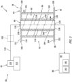
- FIG. 2 partially illustrates an assembly 76 of the turbine engine 14.
- This engine assembly 76 includes a vane array structure 78 and a fluid system 80; e.g., an air delivery system.
- the fluid system 80 includes an air source 82, an air particle separator 84 (APS), an engine structure 86 with an internal volume 88, and a waste air passage 90.
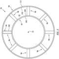
- the vane array structure 78 includes a radial inner platform 92 and a radial outer platform 94.
- the vane array structure 78 also includes a plurality of stator vanes 96 arranged circumferentially about the centerline axis 22 in an array; e.g., a circular array.
- the inner platform 92 of FIG. 2 extends axially along the centerline axis 22 from an upstream end 98 of the inner platform 92 to a downstream end 100 of the inner platform 92.
- the inner platform 92 extends radially between and to a radial inner side 102 of the inner platform 92 and a radial outer side 104 of the inner platform 92.
- the inner platform 92 and its outer side 104 form an inner peripheral boundary of the core flowpath 62 longitudinally through the vane array structure 78.
- the inner platform 92 of FIG. 3 extends circumferentially about (e.g., completely around) the centerline axis 22.
- the inner platform 92 may thereby have a full-hoop (e.g., tubular) geometry.
- the outer platform 94 of FIG. 2 extends axially along the centerline axis 22 from an upstream end 106 of the outer platform 94 to a downstream end 108 of the outer platform 94.
- the outer platform 94 extends radially between and to a radial inner side 110 of the outer platform 94 and a radial outer side 112 of the outer platform 94.
- the outer platform 94 and its inner side 110 form an outer peripheral boundary of the core flowpath 62 longitudinally through the vane array structure 78.
- the outer platform 94 of FIG. 3 extends circumferentially about (e.g., completely around) the centerline axis 22.
- the outer platform 94 may thereby have a full-hoop (e.g., tubular) geometry.
- the outer platform 94 of FIG. 2 is spaced radially outboard of and axially overlaps the inner platform 92 and the stator vanes 96.
- the outer platform 94 may thereby circumscribe the inner platform 92 and the array of the stator vanes 96; see also FIG. 3 .
- the stator vanes 96 are arranged radially between the inner platform 92 and the outer platform 94. Each of the stator vanes 96 extends radially across the core flowpath 62 from the inner platform 92 to the outer platform 94. Each of the stator vanes 96 is connected to the inner platform 92 at (e.g., on, adjacent or proximate) the inner platform outer side 104. Each stator vane 96, for example, may be mechanically fastened (e.g., removably attached), bonded and/or otherwise attached to the inner platform 92. Alternatively, it is contemplated each stator vane 96 may be formed integral with the inner platform 92.
- Each of the stator vanes 96 is connected to the outer platform 94 at the outer platform inner side 110.
- Each stator vane 96 may be mechanically fastened (e.g., removably attached), bonded and/or otherwise attached to the outer platform 94.
- each stator vane 96 may be formed integral with the outer platform 94.
- the vane array structure 78 may be arranged at various locations along the core flowpath 62, forming a respective portion of the core flowpath 62.
- the vane array structure 78 may be arranged longitudinally along the core flowpath 62 between the LPT section 32B and the core exhaust 68.
- the vane array structure 78 may be configured as (or may be included as part of) a turbine exhaust case 114 (TEC) of the turbine engine 14.
- the vane array structure 78 may be arranged longitudinally along the core flowpath 62 between the combustor section 31 and the HPT section 32A.
- the vane array structure 78 may be configured as a combustor outlet nozzle and/or a turbine inlet nozzle 116.
- the vane array structure 78 may be arranged longitudinally along the core flowpath 62 between the HPT section 32A and the LPT section 32B. With such an arrangement, the vane array structure 78 may be configured as (or may be included as part of) a mid-turbine frame 118.
- vane array structure 78 may alternatively be arranged longitudinally along the core flowpath 62 upstream of the combustor 72 (e.g., along the HPC section 30B) for select other turbine engine configurations.
- the vane array structure 78 is generally described below as being arranged downstream of the combustor 72 along the core flowpath 62 and, more particularly, as being configured as the turbine exhaust case 114.
- the air source 82 is configured to provide compressed air to the air particle separator 84.
- This air source 82 may be configured as a bleed orifice 120 (or multiple bleed orifices) along an engine flowpath 122 of the turbine engine 14.
- the bleed orifice 120 is configured to bleed a relatively small quantity of air from the engine flowpath 122, and direct the bleed air into an inlet passage 124 of the fluid system 80.
- This inlet passage 124 fluidly couples the bleed orifice 120 to an input air inlet 126 into the air particle separator 84.
- the engine flowpath 122 may be the core flowpath 62 or the bypass flowpath 64.
- the bleed orifice 120 is arranged upstream of the vane array structure 78 along the core flowpath 62.
- the bleed orifice 120 may be arranged along the compressor section 30 (e.g., the HPC section 30B) or between the compressor section 30 and the combustor 72 (e.g., along a plenum surrounding the combustor 72).
- the present disclosure is not limited to such an exemplary arrangement.
- the air particle separator 84 of FIG. 2 receives input air (the bleed air) from the air source 82 through its input air inlet 126. Under certain conditions, debris such as dirt, sand and/or the like may be entrained with (e.g., carried by) the input air.
- the air particle separator 84 is configured to substantially separate out this debris to provide two different output flows - clean air and waste air (e.g., dirty air).
- the clean air may be substantially (or completely) devoid of the debris; e.g., include less than twenty percent (20%), ten percent (10%) or five percent (5%) of the debris entrained in the input air. This clean air is output from the air particle separator 84 through a clean air outlet 128 of the air particle separator 84.
- the waste air may include a substantial portion (or all) of the debris; e.g., include more than eighty percent (80%), ninety percent (90%) or ninety-five percent (95%) of the debris entrained in the input air.
- This waste air is output from the air particle separator 84 through a waste air outlet 130 (e.g., a dirty air outlet) of the air particle separator 84.
- An example of this air particle separator 84 is a vortex air particle separator; e.g., a vortex tube separator.
- Various other types of air particle separators are known in the art, and the present disclosure is not limited to any particular ones thereof. However, it is contemplated the vortex air particle separator may be particularly well suited for locating within the vane array structure 78 as described below.
- the air particle separator 84 of FIG. 2 is disposed within a respective one of the stator vanes 96; e.g., a hollow stator vane. More particularly, the air particle separator 84 is disposed within and/or forms an internal channel 132 within the respective stator vane 96. This internal channel 132 may extend spanwise along a span line 134 of the respective stator vane 96 (e.g., radially) through the vane array structure 78 and its respective stator vane 96 from a radial outer end 136 of the internal channel 132 at the outer platform 94 to a radial inner end 138 of the internal channel 132 at the inner platform 92.
- This internal channel 132 may extend spanwise along a span line 134 of the respective stator vane 96 (e.g., radially) through the vane array structure 78 and its respective stator vane 96 from a radial outer end 136 of the internal channel 132 at the outer platform 94 to a radial
- the internal channel 132 and, thus, the air particle separator 84 are separated (e.g., fluidly decoupled) from the waste air passage 90 by an interior wall 140 within the respective stator vane 96.
- the interior wall 140 extends longitudinally along the internal channel 132 from the channel outer end 136 to the channel inner end 138, and circumferentially around the internal channel 132.
- the input air inlet 126 is disposed at the channel outer end 136.
- the clean air outlet 128 is disposed at the channel inner end 138.
- the waste air outlet 130 is disposed next to or near the channel inner end 138, for example in the interior wall 140.
- the air particle separator 84 may be formed as an integral part of the respective stator vane 96. In other embodiments, the air particle separator 84 may be assembled with and attached to the respective stator vane 96.
- the engine structure 86 of FIG. 2 is configured to house one or more engine bearings 142 within the internal volume 88; e.g., one or more of the bearings 58 of FIG. 1 .
- the internal volume 88 may be a bearing compartment for the engine bearings 142.
- the present disclosure is not limited to such an exemplary engine structure arrangement.
- the internal volume 88 may be configured as another cavity, passage, flow circuit, etc. within the turbine engine 14 which receives air for cooling, pressurization and/or otherwise.
- the engine structure 86 may alternatively be configured as one of the turbine rotors 42, 43 (see FIG. 1 ), and the internal volume 88 may be an internal cooling circuit within the respective turbine rotor 42, 43.
- the internal volume 88 is fluidly coupled with and downstream of the clean air outlet 128.
- the air particle separator 84 is thereby configured to direct the clean air into the internal volume 88 through its clean air outlet 128 during turbine engine operation.
- the waste air passage 90 is disposed within the respective stator vane 96 with the air particle separator 84.
- the waste air passage 90 of FIG. 2 extends spanwise along the span line 134 of the respective stator vane 96 from or about the channel inner end 138 at the inner platform 92 to or about the channel outer end 136 at the outer platform 94.
- the waste air passage 90 of FIG. 2 is formed by and laterally (e.g., radially relative to the span line 134) between the interior wall 140 and an exterior wall 144 of the respective stator vane 96.
- This exterior wall 144 may form a lateral peripheral boundary of the core flowpath 62 within the vane array structure 78; e.g., the exterior wall 144 may be an exterior fairing / shell of the respective stator vane 96.
- the exterior wall 144 thereby separates (e.g., fluidly decouples) the waste air passage 90 from the core flowpath 62.
- the waste air passage 90 extends circumferentially about the elements 84, 132, 134 and 140.
- the passage outlet 146 may be disposed spanwise / radially at or about the outer platform 94.
- the passage outlet 146 of FIG. 2 is disposed in the exterior wall 144. With this arrangement, the passage outlet 146 may be fluidly coupled with the core flowpath 62. In another example, referring to FIG. 4 , the passage outlet 146 may be disposed in the outer platform 94. With this arrangement, the passage outlet 146 may be fluidly coupled with a volume 148 radially outboard of the vane array structure 78 such as, but not limited to, the bypass flowpath 64 (see FIG. 1 ).
- the air particle separator 84 receives the input air from the air source 82.
- the air particle separator 84 separates the input air into the clean air and the waste air, which waste air includes some or all of the debris entrained with the input air.
- the clean air outlet 128 directs the clean air to the engine structure 86 and its internal volume 88 to, for example, pressurize the internal volume 88 (e.g., the bearing compartment). By providing this clean air to the internal volume 88, a likelihood of contaminating lubricant provided to the engine bearings 142 within the internal volume 88 (e.g., with the debris in the input air) is reduced or eliminated.
- the waste air outlet 130 directs the waste air to the waste air passage 90 to cool the respective stator vane 96.
- the waste air is directed through the waste air passage 90 and along the exterior wall 144 prior to being exhausted into the core flowpath 62 (or the bypass flowpath 64 of FIG. 4 ) via the passage outlet 146.
- the waste air may thereby cool the exterior wall 144 of the respective stator vane 96 via convection, which exterior wall 144 is heated by the combustion products flowing in the core flowpath 62.
- the waste air may also provide an air buffer (e.g., thermal insulation) between the core flowpath 62 and the air particle separator 84.
- This air buffering may reduce or prevent heating of the air flowing in the air particle separator 84 by heat energy from the combustion products flowing in the core flowpath 62.
- the air particle separator 84 may thereby provide relatively cool clean air to the engine structure 86 and its internal volume 88, which in turn may reduce heating of the lubricant within the internal volume 88.
- the waste air may shield the air particle separator 84 enough from the combustion products within the core flowpath 62 to reduce or eliminate a need for a heat exchanger (e.g., an air cooler) between the air source 82 and the air particle separator 84.
- a heat exchanger 150 may be arranged between the air source 82 and the air particle separator 84 to facilitate provision of even cooler clean air to the engine structure 86 and its internal volume 88.
- the engine assembly 76 may be included in various turbine engines other than the one described above.
- the engine assembly 76 may be included in a turbine engine with a single spool, with two spools (e.g., see FIG. 1 ), or with more than two spools.
- the turbine engine is described above with respect to aircraft powerplant applications, it is contemplated the turbine engine may alternatively be configured for other (non-aircraft) applications.
- the powerplant 10, for example, may be configured as (or included as part of) an industrial power generation system. The present disclosure therefore is not limited to any particular types or configurations of turbine engines.
Landscapes
- Engineering & Computer Science (AREA)
- Chemical & Material Sciences (AREA)
- Combustion & Propulsion (AREA)
- Mechanical Engineering (AREA)
- General Engineering & Computer Science (AREA)
- Physics & Mathematics (AREA)
- Fluid Mechanics (AREA)
- Structures Of Non-Positive Displacement Pumps (AREA)
Abstract
An assembly (76) is provided for a turbine engine (14). This assembly (76) includes a vane array structure (78) and an air particle separator (84). The vane array structure (78) includes an inner platform (92), an outer platform (94) and a plurality of vanes (96). The inner platform (92) forms an inner peripheral boundary of a flowpath (62) through the vane array structure (78). The outer platform (94) forms an outer peripheral boundary of the flowpath (62) through the vane array structure (78). The vanes (96) are arranged circumferentially about an axis (22). Each of the vanes (96) extends radially across the flowpath (62) from the inner platform (92) to the outer platform (94). The vanes (96) include a first vane. The air particle separator (84) is arranged within the first vane.
Description
- This disclosure relates generally to a turbine engine and, more particularly, to providing clean air to an internal volume within the turbine engine.
- It is known in the art to provide a bearing compartment of a turbine engine with compressed air. Various systems and methods are known in the art for providing the compressed air to the bearing compartment. While these known systems and methods have various benefits, there is still room in the art for improvement.
- According to an aspect of the present disclosure, an assembly is provided for a turbine engine. This assembly includes a vane array structure and an air particle separator. The vane array structure includes an inner platform, an outer platform and a plurality of vanes. The inner platform forms an inner peripheral boundary of a flowpath through the vane array structure. The outer platform forms an outer peripheral boundary of the flowpath through the vane array structure. The vanes are arranged circumferentially about an axis. Each of the vanes extends radially across the flowpath from the inner platform to the outer platform. The vanes include a first vane. The air particle separator is arranged within the first vane.
- According to another aspect of the present disclosure, another assembly is provided for a turbine engine. This assembly includes a vane array structure and an air particle separator. The vane array structure includes an inner platform, an outer platform and a plurality of vanes. The inner platform forms an inner peripheral boundary of a flowpath through the vane array structure. The outer platform forms an outer peripheral boundary of the flowpath through the vane array structure. The vanes are arranged circumferentially about an axis. Each of the vanes extends radially across the flowpath from the inner platform to the outer platform. The vanes include a first vane. The first vane includes a channel and a passage that extends around the channel within the first vane. The air particle separator includes an input air inlet, a clean air outlet and a waste air outlet. The input air inlet is fluidly coupled with the clean air outlet and the waste air outlet. The waste air outlet is fluidly coupled with and configured to direct waste air to the passage.
- According to still another aspect of the present disclosure, a method of operation is provided. This method includes: directing bleed air into a vane of a vane array structure within a turbine engine, wherein the vane extends across a core flowpath within the turbine engine; processing the bleed air within the vane to provide clean air and waste air, wherein the waste air includes more debris than the clean air; cooling the vane using the waste air; and directing the clean air into a bearing compartment within the turbine engine.
- The following optional features may be applied to any of the above aspects.
- The passage may spiral around the channel.
- The air particle separator may be disposed in the channel.
- The assembly may also include an engine structure with an internal volume. The clean air outlet may be fluidly coupled with and configured to direct clean air to the internal volume.
- The air particle separator may be configured as or otherwise include a vortex air particle separator.
- The assembly may also include an air source. The air particle separator may be fluidly coupled with and configured to receive air from the air source.
- The air source may be configured as or otherwise include a bleed orifice. The bleed orifice may be configured to bleed air from the flowpath upstream of the vane array structure.
- The assembly may also include an engine core including a compressor section, a combustor section and a turbine section. The flowpath may extend through the compressor section, the combustor section and the turbine section from an inlet into the flowpath to an exhaust from the flowpath. The bleed orifice may be arranged along the flowpath upstream of a combustor within the combustor section.
- The vane array structure may be arranged along the flowpath downstream of the combustor.
- The assembly may also include an engine core and a bypass flowpath bypassing the engine core. The engine core may include a compressor section, a combustor section and a turbine section. The flowpath may be a core flowpath which extends through the compressor section, the combustor section and the turbine section from an inlet into the core flowpath to an exhaust from the core flowpath. The air source may be configured as or otherwise include a bleed orifice. The bleed orifice may be configured to bleed air from the bypass flowpath.
- The assembly may also include a bearing compartment radially inboard of the vane array structure. An outlet of the air particle separator may be fluidly coupled with and configured to direct cleaned air to the bearing compartment.
- An outlet of the air particle separator may be fluidly coupled with and configured to direct waste air to the flowpath.
- The assembly may also include an engine core and a bypass flowpath bypassing the engine core. The engine core may include a compressor section, a combustor section and a turbine section. The flowpath may be a core flowpath which extends through the compressor section, the combustor section and the turbine section from an inlet into the core flowpath to an exhaust from the core flowpath. An outlet of the air particle separator may be fluidly coupled with and configured to direct waste air to the bypass flowpath.
- An outlet of the air particle separator may be configured to direct waste air to a passage of the first vane. The passage may be located between the air particle separator and the flowpath.
- The passage may circumscribe the air particle separator.
- The passage may spiral around a span line of the first vane.
- The assembly may also include an engine core including a compressor section, a combustor section and a turbine section. The flowpath may extend through the compressor section, the combustor section and the turbine section from an inlet into the flowpath to an exhaust from the flowpath. The vane array structure may be disposed along the flowpath downstream of the turbine section.
- The assembly may also include a propulsor rotor and an engine core configured to drive rotation of the propulsor rotor. The engine core may include a compressor section, a combustor section and a turbine section. The flowpath may extend through the compressor section, the combustor section and the turbine section from an inlet into the flowpath to an exhaust from the flowpath.
- The present disclosure may include any one or more of the individual features disclosed above and/or below alone or in any combination thereof.
- The foregoing features and the operation of the invention will become more apparent in light of the following description and the accompanying drawings.
-
-
FIG. 1 is a partial side schematic illustration of a powerplant for an aircraft. -
FIG. 2 is a partial side schematic illustration of an assembly for the aircraft powerplant with a first passage outlet arrangement. -
FIG. 3 is a schematic illustration of a vane array structure with an air particle separator. -
FIG. 4 is a partial side schematic illustration of the powerplant assembly with a second passage outlet arrangement. -
FIG. 1 illustrates apowerplant 10 for an aircraft. The aircraft may be an airplane, a helicopter, a drone (e.g., an unmanned aerial vehicle (UAV)) or any other manned or unmanned aerial vehicle or system. Thepowerplant 10 may be configured as, or otherwise included as part of, a propulsion system for the aircraft. Thepowerplant 10 may also or alternatively be configured as, or otherwise included as part of, an electrical power system for the aircraft. Thepowerplant 10 ofFIG. 1 includes a mechanical load 12 and agas turbine engine 14 configured to power the mechanical load 12. - The mechanical load 12 of
FIG. 1 includes at least one driven rotor 16. This driven rotor 16 may be configured as a bladed propulsor rotor for the aircraft propulsion system. The propulsor rotor may be a ducted propulsor rotor or an open propulsor rotor; e.g., an un-ducted propulsor rotor. An example of the ducted propulsor rotor is a fan rotor 18 for a ducted propulsion system; e.g., a turbofan propulsion system. Examples of the open propulsor rotor include a propeller rotor for a propeller propulsion system (e.g., a turboprop propulsion system), a rotorcraft rotor (e.g., a main helicopter rotor) for a rotorcraft propulsion system (e.g., a turboshaft propulsion system), a pusher fan rotor for a pusher fan propulsion system, and a propfan rotor for a propfan propulsion system. Alternatively, the driven rotor 16 may be configured as a generator rotor of an electric power generator for the aircraft electrical power system; e.g., an auxiliary power unit (APU) system. However, for ease of description, the mechanical load 12 is described below as a fan section 20, and the driven rotor 16 is described below as the fan rotor 18 within the fan section 20. - The
turbine engine 14 has acenterline axis 22, and extends axially along thecenterline axis 22 from anupstream end 24 of theturbine engine 14 to adownstream end 26 of theturbine engine 14. Theturbine engine 14 ofFIG. 1 includes the fan section 20 and a turbine engine core 28 (e.g., a gas generator) configured to power operation of the fan section 20. Theengine core 28 includes acompressor section 30, acombustor section 31 and aturbine section 32. Thecompressor section 30 ofFIG. 1 includes a low pressure compressor (LPC)section 30A and a high pressure compressor (HPC)section 30B. Theturbine section 32 ofFIG. 1 includes a high pressure turbine (HPT)section 32A and a low pressure turbine (LPT)section 32B. - The
engine sections 20 and 30A-32B may be arranged sequentially along thecenterline axis 22 within anengine housing 34. Thisengine housing 34 includes an inner case 36 (e.g., a core case) and an outer case 38 (e.g., a fan case). Theinner case 36 may house one or more of theengine sections 30A-32B; e.g., theengine core 28. Theouter case 38 may house at least the fan section 20. - The
LPC section 30A includes a low pressure compressor (LPC)rotor 40. TheHPC section 30B includes a high pressure compressor (HPC)rotor 41. TheHPT section 32A includes a high pressure turbine (HPT)rotor 42. TheLPT section 32B includes a low pressure turbine (LPT)rotor 43. Each of these engine rotors 40-43 and the fan rotor 18 includes a plurality of rotor blades arranged circumferentially around and connected to one or more respective rotor disks. The rotor blades, for example, may be formed integral with or mechanically fastened, welded, brazed and/or otherwise attached to the respective rotor disk(s). - The
HPC rotor 41 is coupled to and rotatable with theHPT rotor 42. TheHPC rotor 41 ofFIG. 1 , for example, is connected to theHPT rotor 42 by ahigh speed shaft 46. At least (or only) theHPC rotor 41, theHPT rotor 42 and thehigh speed shaft 46 collectively form a highspeed rotating assembly 48; e.g., a high speed spool. - The
LPC rotor 40 is coupled to and rotatable with theLPT rotor 43. TheLPC rotor 40 ofFIG. 1 , for example, is connected to theLPT rotor 43 by alow speed shaft 50. At least (or only) theLPC rotor 40, theLPT rotor 43 and thelow speed shaft 50 collectively form a lowspeed rotating assembly 52; e.g., a low speed spool. This lowspeed rotating assembly 52 is further coupled to the fan rotor 18 (the driven rotor 16) through adrivetrain 54. Thisdrivetrain 54 may be configured as a geared drivetrain, where a geartrain 56 (e.g., a transmission, a speed change device, an epicyclic geartrain, etc.) is disposed between and operatively couples the fan rotor 18 to the lowspeed rotating assembly 52 and itsLPT rotor 43. With this arrangement, the fan rotor 18 may rotate at a different (e.g., slower) rotational velocity than the lowspeed rotating assembly 52 and itsLPT rotor 43. However, thedrivetrain 54 may alternatively be configured as a direct drive drivetrain, where thegeartrain 56 is omitted. With this arrangement, the fan rotor 18 rotates at a common (the same) rotational velocity as the lowspeed rotating assembly 52 and itsLPT rotor 43. - Referring again to
FIG. 1 , each of therotating assemblies bearings 58; e.g., rolling element and/or thrust bearings. Each of thesebearings 58 is connected to theengine housing 34 by at least one stationary structure such as, for example, a bearing support frame. Each of therotating assemblies centerline axis 22. - During operation of the
powerplant 10 ofFIG. 1 , air enters thepowerplant 10 and itsturbine engine 14 through anairflow inlet 60. This air is directed through the fan section 20 and into a core flowpath 62 (e.g., annular core flowpath) and a bypass flowpath 64 (e.g., annular bypass flowpath). Thecore flowpath 62 extends through theengine core 28 and sequentially longitudinally through theengine sections 30A-32B from anairflow inlet 66 into thecore flowpath 62 to a combustion products exhaust 68 from thecore flowpath 62. The air within thecore flowpath 62 may be referred to as "core air". The bypass flowpath 64 extends through a bypass duct and bypasses (e.g., is radially outboard of and extends along) theengine core 28. The air within the bypass flowpath 64 may be referred to as "bypass air". - The core air is compressed by the
LPC rotor 40 and theHPC rotor 41 and directed into a combustion chamber 70 (e.g., an annular combustion chamber) of a combustor 72 (e.g., an annular combustor) in thecombustor section 31. Fuel is injected into thecombustion chamber 70 by one ormore fuel injectors 74 and mixed with the compressed core air to provide a fuel-air mixture. This fuel-air mixture is ignited and combustion products thereof flow through and sequentially cause theHPT rotor 42 and theLPT rotor 43 to rotate. The rotation of theHPT rotor 42 and theLPT rotor 43 respectively drive rotation of theHPC rotor 41 and theLPC rotor 40 and, thus, compression of the air received from thecore inlet 66. The rotation of theLPT rotor 43 also drives rotation of the fan rotor 18 (the driven rotor 16), which propels the bypass air through and out of the bypass flowpath 64. The propulsion of the bypass air may account for a majority of thrust generated by the aircraft propulsion system. Of course, where the mechanical load 12 also or alternatively includes the generator rotor, the rotation of theLPT rotor 43 may drive the electric power generator to generate electricity. -
FIG. 2 partially illustrates anassembly 76 of theturbine engine 14. Thisengine assembly 76 includes avane array structure 78 and afluid system 80; e.g., an air delivery system. Thefluid system 80 includes anair source 82, an air particle separator 84 (APS), anengine structure 86 with aninternal volume 88, and awaste air passage 90. - Referring to
FIG. 3 , thevane array structure 78 includes a radialinner platform 92 and a radialouter platform 94. Thevane array structure 78 also includes a plurality ofstator vanes 96 arranged circumferentially about thecenterline axis 22 in an array; e.g., a circular array. - The
inner platform 92 ofFIG. 2 extends axially along thecenterline axis 22 from anupstream end 98 of theinner platform 92 to adownstream end 100 of theinner platform 92. Theinner platform 92 extends radially between and to a radialinner side 102 of theinner platform 92 and a radialouter side 104 of theinner platform 92. Theinner platform 92 and itsouter side 104 form an inner peripheral boundary of thecore flowpath 62 longitudinally through thevane array structure 78. Theinner platform 92 ofFIG. 3 extends circumferentially about (e.g., completely around) thecenterline axis 22. Theinner platform 92 may thereby have a full-hoop (e.g., tubular) geometry. - The
outer platform 94 ofFIG. 2 extends axially along thecenterline axis 22 from anupstream end 106 of theouter platform 94 to adownstream end 108 of theouter platform 94. Theouter platform 94 extends radially between and to a radialinner side 110 of theouter platform 94 and a radialouter side 112 of theouter platform 94. Theouter platform 94 and itsinner side 110 form an outer peripheral boundary of thecore flowpath 62 longitudinally through thevane array structure 78. Theouter platform 94 ofFIG. 3 extends circumferentially about (e.g., completely around) thecenterline axis 22. Theouter platform 94 may thereby have a full-hoop (e.g., tubular) geometry. Theouter platform 94 ofFIG. 2 is spaced radially outboard of and axially overlaps theinner platform 92 and the stator vanes 96. Theouter platform 94 may thereby circumscribe theinner platform 92 and the array of thestator vanes 96; see alsoFIG. 3 . - The stator vanes 96 are arranged radially between the
inner platform 92 and theouter platform 94. Each of thestator vanes 96 extends radially across the core flowpath 62 from theinner platform 92 to theouter platform 94. Each of thestator vanes 96 is connected to theinner platform 92 at (e.g., on, adjacent or proximate) the inner platformouter side 104. Eachstator vane 96, for example, may be mechanically fastened (e.g., removably attached), bonded and/or otherwise attached to theinner platform 92. Alternatively, it is contemplated eachstator vane 96 may be formed integral with theinner platform 92. Each of thestator vanes 96 is connected to theouter platform 94 at the outer platforminner side 110. Eachstator vane 96, for example, may be mechanically fastened (e.g., removably attached), bonded and/or otherwise attached to theouter platform 94. Alternatively, it is contemplated eachstator vane 96 may be formed integral with theouter platform 94. - Referring to
FIG. 1 , thevane array structure 78 may be arranged at various locations along thecore flowpath 62, forming a respective portion of thecore flowpath 62. For example, thevane array structure 78 may be arranged longitudinally along thecore flowpath 62 between theLPT section 32B and thecore exhaust 68. With such an arrangement, thevane array structure 78 may be configured as (or may be included as part of) a turbine exhaust case 114 (TEC) of theturbine engine 14. In another example, thevane array structure 78 may be arranged longitudinally along thecore flowpath 62 between thecombustor section 31 and theHPT section 32A. With such an arrangement, thevane array structure 78 may be configured as a combustor outlet nozzle and/or a turbine inlet nozzle 116. In still another example, thevane array structure 78 may be arranged longitudinally along thecore flowpath 62 between theHPT section 32A and theLPT section 32B. With such an arrangement, thevane array structure 78 may be configured as (or may be included as part of) a mid-turbine frame 118. While the foregoing vane array structure locations are downstream of thecombustor 72 along thecore flowpath 62, it is contemplated thevane array structure 78 may alternatively be arranged longitudinally along thecore flowpath 62 upstream of the combustor 72 (e.g., along theHPC section 30B) for select other turbine engine configurations. However, for ease of description, thevane array structure 78 is generally described below as being arranged downstream of thecombustor 72 along thecore flowpath 62 and, more particularly, as being configured as the turbine exhaust case 114. - Referring to
FIG. 2 , theair source 82 is configured to provide compressed air to theair particle separator 84. Thisair source 82, for example, may be configured as a bleed orifice 120 (or multiple bleed orifices) along anengine flowpath 122 of theturbine engine 14. Thebleed orifice 120 is configured to bleed a relatively small quantity of air from theengine flowpath 122, and direct the bleed air into aninlet passage 124 of thefluid system 80. Thisinlet passage 124 fluidly couples thebleed orifice 120 to aninput air inlet 126 into theair particle separator 84. Referring toFIG. 1 , theengine flowpath 122 may be thecore flowpath 62 or the bypass flowpath 64. Where theengine flowpath 122 is thecore flowpath 62, thebleed orifice 120 is arranged upstream of thevane array structure 78 along thecore flowpath 62. Thebleed orifice 120, for example, may be arranged along the compressor section 30 (e.g., theHPC section 30B) or between thecompressor section 30 and the combustor 72 (e.g., along a plenum surrounding the combustor 72). The present disclosure, however, is not limited to such an exemplary arrangement. - The
air particle separator 84 ofFIG. 2 receives input air (the bleed air) from theair source 82 through itsinput air inlet 126. Under certain conditions, debris such as dirt, sand and/or the like may be entrained with (e.g., carried by) the input air. Theair particle separator 84 is configured to substantially separate out this debris to provide two different output flows - clean air and waste air (e.g., dirty air). The clean air may be substantially (or completely) devoid of the debris; e.g., include less than twenty percent (20%), ten percent (10%) or five percent (5%) of the debris entrained in the input air. This clean air is output from theair particle separator 84 through aclean air outlet 128 of theair particle separator 84. The waste air may include a substantial portion (or all) of the debris; e.g., include more than eighty percent (80%), ninety percent (90%) or ninety-five percent (95%) of the debris entrained in the input air. This waste air is output from theair particle separator 84 through a waste air outlet 130 (e.g., a dirty air outlet) of theair particle separator 84. An example of thisair particle separator 84 is a vortex air particle separator; e.g., a vortex tube separator. Various other types of air particle separators are known in the art, and the present disclosure is not limited to any particular ones thereof. However, it is contemplated the vortex air particle separator may be particularly well suited for locating within thevane array structure 78 as described below. - The
air particle separator 84 ofFIG. 2 is disposed within a respective one of thestator vanes 96; e.g., a hollow stator vane. More particularly, theair particle separator 84 is disposed within and/or forms aninternal channel 132 within therespective stator vane 96. Thisinternal channel 132 may extend spanwise along aspan line 134 of the respective stator vane 96 (e.g., radially) through thevane array structure 78 and itsrespective stator vane 96 from a radialouter end 136 of theinternal channel 132 at theouter platform 94 to a radialinner end 138 of theinternal channel 132 at theinner platform 92. Theinternal channel 132 and, thus, theair particle separator 84 are separated (e.g., fluidly decoupled) from thewaste air passage 90 by aninterior wall 140 within therespective stator vane 96. Theinterior wall 140 extends longitudinally along theinternal channel 132 from the channelouter end 136 to the channelinner end 138, and circumferentially around theinternal channel 132. Theinput air inlet 126 is disposed at the channelouter end 136. Theclean air outlet 128 is disposed at the channelinner end 138. Thewaste air outlet 130 is disposed next to or near the channelinner end 138, for example in theinterior wall 140. - In some embodiments, the
air particle separator 84 may be formed as an integral part of therespective stator vane 96. In other embodiments, theair particle separator 84 may be assembled with and attached to therespective stator vane 96. - The
engine structure 86 ofFIG. 2 is configured to house one ormore engine bearings 142 within theinternal volume 88; e.g., one or more of thebearings 58 ofFIG. 1 . Theinternal volume 88, for example, may be a bearing compartment for theengine bearings 142. The present disclosure, however, is not limited to such an exemplary engine structure arrangement. For example, in other embodiments, theinternal volume 88 may be configured as another cavity, passage, flow circuit, etc. within theturbine engine 14 which receives air for cooling, pressurization and/or otherwise. For example, theengine structure 86 may alternatively be configured as one of theturbine rotors 42, 43 (seeFIG. 1 ), and theinternal volume 88 may be an internal cooling circuit within therespective turbine rotor - The
internal volume 88 is fluidly coupled with and downstream of theclean air outlet 128. Theair particle separator 84 is thereby configured to direct the clean air into theinternal volume 88 through itsclean air outlet 128 during turbine engine operation. - The
waste air passage 90 is disposed within therespective stator vane 96 with theair particle separator 84. Thewaste air passage 90 ofFIG. 2 , for example, extends spanwise along thespan line 134 of therespective stator vane 96 from or about the channelinner end 138 at theinner platform 92 to or about the channelouter end 136 at theouter platform 94. Thewaste air passage 90 ofFIG. 2 is formed by and laterally (e.g., radially relative to the span line 134) between theinterior wall 140 and anexterior wall 144 of therespective stator vane 96. Thisexterior wall 144 may form a lateral peripheral boundary of thecore flowpath 62 within thevane array structure 78; e.g., theexterior wall 144 may be an exterior fairing / shell of therespective stator vane 96. Theexterior wall 144 thereby separates (e.g., fluidly decouples) thewaste air passage 90 from thecore flowpath 62. Thewaste air passage 90 extends circumferentially about theelements waste air passage 90 ofFIG. 2 , for example, spirals around theelements waste air passage 90 extends longitudinally from an inlet into the waste air passage 90 (here, thewaste air outlet 130 from the air particle separator 84) to anoutlet 146 from thewaste air passage 90. Thepassage outlet 146 may be disposed spanwise / radially at or about theouter platform 94. Thepassage outlet 146 ofFIG. 2 , for example, is disposed in theexterior wall 144. With this arrangement, thepassage outlet 146 may be fluidly coupled with thecore flowpath 62. In another example, referring toFIG. 4 , thepassage outlet 146 may be disposed in theouter platform 94. With this arrangement, thepassage outlet 146 may be fluidly coupled with avolume 148 radially outboard of thevane array structure 78 such as, but not limited to, the bypass flowpath 64 (seeFIG. 1 ). - During operation of the
fluid system 80 ofFIG. 2 , theair particle separator 84 receives the input air from theair source 82. Theair particle separator 84 separates the input air into the clean air and the waste air, which waste air includes some or all of the debris entrained with the input air. Theclean air outlet 128 directs the clean air to theengine structure 86 and itsinternal volume 88 to, for example, pressurize the internal volume 88 (e.g., the bearing compartment). By providing this clean air to theinternal volume 88, a likelihood of contaminating lubricant provided to theengine bearings 142 within the internal volume 88 (e.g., with the debris in the input air) is reduced or eliminated. Concurrently, thewaste air outlet 130 directs the waste air to thewaste air passage 90 to cool therespective stator vane 96. The waste air is directed through thewaste air passage 90 and along theexterior wall 144 prior to being exhausted into the core flowpath 62 (or the bypass flowpath 64 ofFIG. 4 ) via thepassage outlet 146. The waste air may thereby cool theexterior wall 144 of therespective stator vane 96 via convection, whichexterior wall 144 is heated by the combustion products flowing in thecore flowpath 62. The waste air may also provide an air buffer (e.g., thermal insulation) between thecore flowpath 62 and theair particle separator 84. This air buffering may reduce or prevent heating of the air flowing in theair particle separator 84 by heat energy from the combustion products flowing in thecore flowpath 62. Theair particle separator 84 may thereby provide relatively cool clean air to theengine structure 86 and itsinternal volume 88, which in turn may reduce heating of the lubricant within theinternal volume 88. It is contemplated the waste air may shield theair particle separator 84 enough from the combustion products within thecore flowpath 62 to reduce or eliminate a need for a heat exchanger (e.g., an air cooler) between theair source 82 and theair particle separator 84. Of course, it is contemplated aheat exchanger 150 may be arranged between theair source 82 and theair particle separator 84 to facilitate provision of even cooler clean air to theengine structure 86 and itsinternal volume 88. - The
engine assembly 76 may be included in various turbine engines other than the one described above. Theengine assembly 76, for example, may be included in a turbine engine with a single spool, with two spools (e.g., seeFIG. 1 ), or with more than two spools. Moreover, while the turbine engine is described above with respect to aircraft powerplant applications, it is contemplated the turbine engine may alternatively be configured for other (non-aircraft) applications. Thepowerplant 10, for example, may be configured as (or included as part of) an industrial power generation system. The present disclosure therefore is not limited to any particular types or configurations of turbine engines. - While various embodiments of the present disclosure have been described, it will be apparent to those of ordinary skill in the art that many more embodiments and implementations are possible within the scope of the disclosure. For example, the present disclosure as described herein includes several aspects and embodiments that include particular features. Although these features may be described individually, it is within the scope of the present disclosure that some or all of these features may be combined with any one of the aspects and remain within the scope of the disclosure. Accordingly, the present disclosure is not to be restricted except in light of the attached claims and their equivalents.
Claims (15)
- An assembly (76) for a turbine engine (14), comprising:a vane array structure (78) including an inner platform (92), an outer platform (94) and a plurality of vanes (96), the inner platform (92) forming an inner peripheral boundary of a flowpath (62) through the vane array structure (78), the outer platform (94) forming an outer peripheral boundary of the flowpath (62) through the vane array structure (78), the plurality of vanes (96) arranged circumferentially about an axis (22), each of the plurality of vanes (96) extending radially across the flowpath (62) from the inner platform (92) to the outer platform (94), and the plurality of vanes (96) comprising a first vane; andan air particle separator (84) arranged within the first vane.
- The assembly (76) of claim 1, wherein the air particle separator (84) comprises a vortex air particle separator.
- The assembly (76) of claim 1 or 2, further comprising:an air source (82);the air particle separator (84) fluidly coupled with and configured to receive air from the air source (82).
- The assembly (76) of claim 3, wherein:the air source (82) comprises a bleed orifice (120); andthe bleed orifice (120) is configured to bleed air from the flowpath (62) upstream of the vane array structure (78).
- The assembly (76) of claim 4, further comprising:an engine core (28) including a compressor section (30), a combustor section (31) and a turbine section (32);the flowpath (62) extending through the compressor section (30), the combustor section (31) and the turbine section (32) from an inlet (66) into the flowpath (62) to an exhaust (68) from the flowpath (62); andthe bleed orifice (120) arranged along the flowpath (62) upstream of a combustor (72) within the combustor section (31),wherein, optionally, the vane array structure (78) is arranged along the flowpath (62) downstream of the combustor (72).
- The assembly (76) of claim 3, 4 or 5, further comprising:an engine core (28) including a compressor section (30), a combustor section (31) and a turbine section (32), the flowpath comprising a core flowpath (62) which extends through the compressor section (30), the combustor section (31) and the turbine section (32) from an inlet (66) into the core flowpath (62) to an exhaust (68) from the core flowpath (62); anda bypass flowpath (64) bypassing the engine core (28);the air source (82) comprising a bleed orifice (120), and the bleed orifice (120) configured to bleed air from the bypass flowpath (64).
- The assembly (76) of any preceding claim, further comprising:a bearing compartment (88) radially inboard of the vane array structure (78);an outlet (128) of the air particle separator (84) fluidly coupled with and configured to direct cleaned air to the bearing compartment (88).
- The assembly (76) of any preceding claim, wherein an outlet (146) of the air particle separator (84) is fluidly coupled with and configured to direct waste air to the flowpath (62).
- The assembly (76) of any preceding claim, further comprising:an engine core (28) including a compressor section (30), a combustor section (31) and a turbine section (32), the flowpath comprising a core flowpath (62) which extends through the compressor section (30), the combustor section (31) and the turbine section (32) from an inlet (66) into the core flowpath (62) to an exhaust (68) from the core flowpath (62); anda bypass flowpath (64) bypassing the engine core (28);an outlet (146) of the air particle separator (84) fluidly coupled with and configured to direct waste air to the bypass flowpath (64).
- The assembly (76) of any preceding claim, wherein:an outlet (130) of the air particle separator (84) is configured to direct waste air to a passage (90) of the first vane; andthe passage (90) is located between the air particle separator (84) and the flowpath (62), wherein, optionally:the passage (90) circumscribes the air particle separator (84); and/orthe passage (90) spirals around a span line (134) of the first vane.
- The assembly (76) of any preceding claim, further comprising:an engine core (28) including a compressor section (30), a combustor section (31) and a turbine section (32);the flowpath (62) extending through the compressor section (30), the combustor section (31) and the turbine section (32) from an inlet (66) into the flowpath (62) to an exhaust (68) from the flowpath (62); andthe vane array structure (78) disposed along the flowpath (62) downstream of the turbine section (32).
- The assembly (76) of any preceding claim, further comprising:a propulsor rotor (16); andan engine core (28) configured to drive rotation of the propulsor rotor (16), the engine core (28) including a compressor section (30), a combustor section (31) and a turbine section (32);the flowpath (62) extending through the compressor section (30), the combustor section (31) and the turbine section (32) from an inlet (66) into the flowpath (62) to an exhaust (68) from the flowpath (62).
- An assembly (76) for a turbine engine (14), comprising:a vane array structure (78) including an inner platform (92), an outer platform (94) and a plurality of vanes (96), the inner platform (92) forming an inner peripheral boundary of a flowpath (62) through the vane array structure (78), the outer platform (94) forming an outer peripheral boundary of the flowpath (62) through the vane array structure (78), the plurality of vanes (96) arranged circumferentially about an axis (22), each of the plurality of vanes (96) extending radially across the flowpath (62) from the inner platform (92) to the outer platform (94), the plurality of vanes (96) comprising a first vane, and the first vane comprising a channel (132) and a passage (90) that extends around the channel (132) within the first vane; andan air particle separator (84) including an input air inlet (126), a clean air outlet (128) and a waste air outlet (130), the input air inlet (126) fluidly coupled with the clean air outlet (128) and the waste air outlet (130), and the waste air outlet (130) fluidly coupled with and configured to direct waste air to the passage (90);wherein, optionally, the assembly (76) further comprises:an engine structure (86) with an internal volume (88);the clean air outlet (128) fluidly coupled with and configured to direct clean air to the internal volume (88).
- The assembly (76) of claim 13, wherein:the passage (90) spirals around the channel (132); and/orthe air particle separator (84) is disposed in the channel (132).
- A method of operation, comprising:directing bleed air into a vane (96) of a vane array structure (78) within a turbine engine (14), wherein the vane (96) extends across a core flowpath (62) within the turbine engine (14);processing the bleed air within the vane (96) to provide clean air and waste air, wherein the waste air includes more debris than the clean air;cooling the vane (96) using the waste air; anddirecting the clean air into a bearing compartment (88) within the turbine engine (14).
Applications Claiming Priority (1)
| Application Number | Priority Date | Filing Date | Title |
|---|---|---|---|
| US18/224,938 US20250027447A1 (en) | 2023-07-21 | 2023-07-21 | Turbine engine vane array structure with air particle separator |
Publications (1)
| Publication Number | Publication Date |
|---|---|
| EP4495383A1 true EP4495383A1 (en) | 2025-01-22 |
Family
ID=91961978
Family Applications (1)
| Application Number | Title | Priority Date | Filing Date |
|---|---|---|---|
| EP24190070.3A Pending EP4495383A1 (en) | 2023-07-21 | 2024-07-22 | Turbine engine vane array structure with air particle separator |
Country Status (2)
| Country | Link |
|---|---|
| US (1) | US20250027447A1 (en) |
| EP (1) | EP4495383A1 (en) |
Citations (3)
| Publication number | Priority date | Publication date | Assignee | Title |
|---|---|---|---|---|
| JP5908054B2 (en) * | 2014-11-25 | 2016-04-26 | 三菱重工業株式会社 | gas turbine |
| US20170107834A1 (en) * | 2015-10-15 | 2017-04-20 | General Electric Company | Nozzle for a gas turbine engine |
| US20180347466A1 (en) * | 2017-06-05 | 2018-12-06 | General Electric Company | Engine component with insert |
Family Cites Families (12)
| Publication number | Priority date | Publication date | Assignee | Title |
|---|---|---|---|---|
| FR2765265B1 (en) * | 1997-06-26 | 1999-08-20 | Snecma | BLADED COOLING BY HELICAL RAMP, CASCADE IMPACT AND BY BRIDGE SYSTEM IN A DOUBLE SKIN |
| US6969237B2 (en) * | 2003-08-28 | 2005-11-29 | United Technologies Corporation | Turbine airfoil cooling flow particle separator |
| US7665965B1 (en) * | 2007-01-17 | 2010-02-23 | Florida Turbine Technologies, Inc. | Turbine rotor disk with dirt particle separator |
| US8142153B1 (en) * | 2009-06-22 | 2012-03-27 | Florida Turbine Technologies, Inc | Turbine vane with dirt separator |
| US8176720B2 (en) * | 2009-09-22 | 2012-05-15 | Siemens Energy, Inc. | Air cooled turbine component having an internal filtration system |
| GB2498551B (en) * | 2012-01-20 | 2015-07-08 | Rolls Royce Plc | Aerofoil cooling |
| US10196982B2 (en) * | 2015-11-04 | 2019-02-05 | General Electric Company | Gas turbine engine having a flow control surface with a cooling conduit |
| US10294823B2 (en) * | 2016-05-23 | 2019-05-21 | United Technologies Corporation | Dirt evacuation devices |
| US10577954B2 (en) * | 2017-03-27 | 2020-03-03 | Honeywell International Inc. | Blockage-resistant vane impingement tubes and turbine nozzles containing the same |
| US10787912B2 (en) * | 2018-04-25 | 2020-09-29 | Raytheon Technologies Corporation | Spiral cavities for gas turbine engine components |
| US11326516B2 (en) * | 2019-08-15 | 2022-05-10 | Pratt & Whitney Canada Corp. | Removal of contaminants from air for use in aircraft engines |
| US12404806B2 (en) * | 2021-12-15 | 2025-09-02 | Rtx Corporation | High pressure turbine dirt blocker |
-
2023
- 2023-07-21 US US18/224,938 patent/US20250027447A1/en active Pending
-
2024
- 2024-07-22 EP EP24190070.3A patent/EP4495383A1/en active Pending
Patent Citations (3)
| Publication number | Priority date | Publication date | Assignee | Title |
|---|---|---|---|---|
| JP5908054B2 (en) * | 2014-11-25 | 2016-04-26 | 三菱重工業株式会社 | gas turbine |
| US20170107834A1 (en) * | 2015-10-15 | 2017-04-20 | General Electric Company | Nozzle for a gas turbine engine |
| US20180347466A1 (en) * | 2017-06-05 | 2018-12-06 | General Electric Company | Engine component with insert |
Also Published As
| Publication number | Publication date |
|---|---|
| US20250027447A1 (en) | 2025-01-23 |
Similar Documents
| Publication | Publication Date | Title |
|---|---|---|
| US11655767B2 (en) | Gearbox for an engine | |
| CN114941571B (en) | Variable pitch fans for turbomachinery engines | |
| CN114991963A (en) | Three-flow engine with heat exchanger | |
| EP4464881A1 (en) | Pressure control for bifurcated flow of a turbine engine | |
| EP4644678A2 (en) | Separating airflows within an aircraft powerplant | |
| EP4579130A2 (en) | Separating airflows within a turbine engine | |
| EP4509703A1 (en) | Aircraft powerplant with electric powertrain | |
| US12404812B1 (en) | Open rotor aircraft propulsion system with bypass flowpath | |
| EP4495383A1 (en) | Turbine engine vane array structure with air particle separator | |
| EP4385899A1 (en) | Aircraft thermal anti-icing system | |
| EP4361423A2 (en) | Gas turbine engine component with integral heat exchanger | |
| EP4389605A2 (en) | Electric aircraft propulsion unit(s) with multiple propulsor rotors | |
| US12497895B1 (en) | Air cooling system for stator vane structure outer platform | |
| US20250198328A1 (en) | Ventilation system for aircraft propulsion system | |
| EP4579129A1 (en) | Separating airflows within a turbine engine | |
| US12428986B2 (en) | Aircraft propulsion system engine with multiple independent rotating structures | |
| US12404811B1 (en) | Aircraft powerplant gearbox with selectable power coupler | |
| US12523161B1 (en) | Aircraft powerplant gearbox with selectable power coupler | |
| US12421863B2 (en) | Turbine engine tip clearance control system with thrust bearing | |
| US20260062137A1 (en) | Thermal management system for open rotor aircraft propulsion system | |
| US12410712B1 (en) | Rotor blade with apertured cooling air deflector | |
| US12215628B2 (en) | Aircraft system with gas turbine engine powered compressor | |
| US20250305454A1 (en) | Gas turbine engine with heat exchanger assembly | |
| EP4592510A1 (en) | Intermediate case for aircraft propulsion system housing | |
| EP4733566A2 (en) | Thermal management system for open rotor aircraft propulsion system |
Legal Events
| Date | Code | Title | Description |
|---|---|---|---|
| PUAI | Public reference made under article 153(3) epc to a published international application that has entered the european phase |
Free format text: ORIGINAL CODE: 0009012 |
|
| STAA | Information on the status of an ep patent application or granted ep patent |
Free format text: STATUS: THE APPLICATION HAS BEEN PUBLISHED |
|
| AK | Designated contracting states |
Kind code of ref document: A1 Designated state(s): AL AT BE BG CH CY CZ DE DK EE ES FI FR GB GR HR HU IE IS IT LI LT LU LV MC ME MK MT NL NO PL PT RO RS SE SI SK SM TR |
|
| STAA | Information on the status of an ep patent application or granted ep patent |
Free format text: STATUS: REQUEST FOR EXAMINATION WAS MADE |
|
| 17P | Request for examination filed |
Effective date: 20250721 |