EP4495378A1 - Fretting resistant rotary engine housings - Google Patents
Fretting resistant rotary engine housings Download PDFInfo
- Publication number
- EP4495378A1 EP4495378A1 EP24188824.7A EP24188824A EP4495378A1 EP 4495378 A1 EP4495378 A1 EP 4495378A1 EP 24188824 A EP24188824 A EP 24188824A EP 4495378 A1 EP4495378 A1 EP 4495378A1
- Authority
- EP
- European Patent Office
- Prior art keywords
- housing
- coating
- fretting
- side plate
- side housing
- Prior art date
- Legal status (The legal status is an assumption and is not a legal conclusion. Google has not performed a legal analysis and makes no representation as to the accuracy of the status listed.)
- Pending
Links
Images




Classifications
-
- F—MECHANICAL ENGINEERING; LIGHTING; HEATING; WEAPONS; BLASTING
- F01—MACHINES OR ENGINES IN GENERAL; ENGINE PLANTS IN GENERAL; STEAM ENGINES
- F01C—ROTARY-PISTON OR OSCILLATING-PISTON MACHINES OR ENGINES
- F01C1/00—Rotary-piston machines or engines
- F01C1/22—Rotary-piston machines or engines of internal-axis type with equidirectional movement of co-operating members at the points of engagement, or with one of the co-operating members being stationary, the inner member having more teeth or tooth- equivalents than the outer member
-
- F—MECHANICAL ENGINEERING; LIGHTING; HEATING; WEAPONS; BLASTING
- F01—MACHINES OR ENGINES IN GENERAL; ENGINE PLANTS IN GENERAL; STEAM ENGINES
- F01C—ROTARY-PISTON OR OSCILLATING-PISTON MACHINES OR ENGINES
- F01C19/00—Sealing arrangements in rotary-piston machines or engines
- F01C19/005—Structure and composition of sealing elements such as sealing strips, sealing rings and the like; Coating of these elements
-
- F—MECHANICAL ENGINEERING; LIGHTING; HEATING; WEAPONS; BLASTING
- F01—MACHINES OR ENGINES IN GENERAL; ENGINE PLANTS IN GENERAL; STEAM ENGINES
- F01C—ROTARY-PISTON OR OSCILLATING-PISTON MACHINES OR ENGINES
- F01C21/00—Component parts, details or accessories not provided for in groups F01C1/00 - F01C20/00
- F01C21/10—Outer members for co-operation with rotary pistons; Casings
-
- F—MECHANICAL ENGINEERING; LIGHTING; HEATING; WEAPONS; BLASTING
- F01—MACHINES OR ENGINES IN GENERAL; ENGINE PLANTS IN GENERAL; STEAM ENGINES
- F01C—ROTARY-PISTON OR OSCILLATING-PISTON MACHINES OR ENGINES
- F01C21/00—Component parts, details or accessories not provided for in groups F01C1/00 - F01C20/00
- F01C21/10—Outer members for co-operation with rotary pistons; Casings
- F01C21/104—Stators; Members defining the outer boundaries of the working chamber
- F01C21/108—Stators; Members defining the outer boundaries of the working chamber with an axial surface, e.g. side plates
-
- F—MECHANICAL ENGINEERING; LIGHTING; HEATING; WEAPONS; BLASTING
- F02—COMBUSTION ENGINES; HOT-GAS OR COMBUSTION-PRODUCT ENGINE PLANTS
- F02B—INTERNAL-COMBUSTION PISTON ENGINES; COMBUSTION ENGINES IN GENERAL
- F02B55/00—Internal-combustion aspects of rotary pistons; Outer members for co-operation with rotary pistons
- F02B55/08—Outer members for co-operation with rotary pistons; Casings
-
- F—MECHANICAL ENGINEERING; LIGHTING; HEATING; WEAPONS; BLASTING
- F02—COMBUSTION ENGINES; HOT-GAS OR COMBUSTION-PRODUCT ENGINE PLANTS
- F02B—INTERNAL-COMBUSTION PISTON ENGINES; COMBUSTION ENGINES IN GENERAL
- F02B53/00—Internal-combustion aspects of rotary-piston or oscillating-piston engines
- F02B2053/005—Wankel engines
-
- F—MECHANICAL ENGINEERING; LIGHTING; HEATING; WEAPONS; BLASTING
- F04—POSITIVE - DISPLACEMENT MACHINES FOR LIQUIDS; PUMPS FOR LIQUIDS OR ELASTIC FLUIDS
- F04C—ROTARY-PISTON, OR OSCILLATING-PISTON, POSITIVE-DISPLACEMENT MACHINES FOR LIQUIDS; ROTARY-PISTON, OR OSCILLATING-PISTON, POSITIVE-DISPLACEMENT PUMPS
- F04C2230/00—Manufacture
- F04C2230/90—Improving properties of machine parts
- F04C2230/91—Coating
-
- F—MECHANICAL ENGINEERING; LIGHTING; HEATING; WEAPONS; BLASTING
- F04—POSITIVE - DISPLACEMENT MACHINES FOR LIQUIDS; PUMPS FOR LIQUIDS OR ELASTIC FLUIDS
- F04C—ROTARY-PISTON, OR OSCILLATING-PISTON, POSITIVE-DISPLACEMENT MACHINES FOR LIQUIDS; ROTARY-PISTON, OR OSCILLATING-PISTON, POSITIVE-DISPLACEMENT PUMPS
- F04C2240/00—Components
- F04C2240/30—Casings or housings
-
- F—MECHANICAL ENGINEERING; LIGHTING; HEATING; WEAPONS; BLASTING
- F05—INDEXING SCHEMES RELATING TO ENGINES OR PUMPS IN VARIOUS SUBCLASSES OF CLASSES F01-F04
- F05C—INDEXING SCHEME RELATING TO MATERIALS, MATERIAL PROPERTIES OR MATERIAL CHARACTERISTICS FOR MACHINES, ENGINES OR PUMPS OTHER THAN NON-POSITIVE-DISPLACEMENT MACHINES OR ENGINES
- F05C2201/00—Metals
- F05C2201/02—Light metals
- F05C2201/021—Aluminium
-
- F—MECHANICAL ENGINEERING; LIGHTING; HEATING; WEAPONS; BLASTING
- F05—INDEXING SCHEMES RELATING TO ENGINES OR PUMPS IN VARIOUS SUBCLASSES OF CLASSES F01-F04
- F05C—INDEXING SCHEME RELATING TO MATERIALS, MATERIAL PROPERTIES OR MATERIAL CHARACTERISTICS FOR MACHINES, ENGINES OR PUMPS OTHER THAN NON-POSITIVE-DISPLACEMENT MACHINES OR ENGINES
- F05C2201/00—Metals
- F05C2201/90—Alloys not otherwise provided for
- F05C2201/903—Aluminium alloy, e.g. AlCuMgPb F34,37
-
- F—MECHANICAL ENGINEERING; LIGHTING; HEATING; WEAPONS; BLASTING
- F05—INDEXING SCHEMES RELATING TO ENGINES OR PUMPS IN VARIOUS SUBCLASSES OF CLASSES F01-F04
- F05C—INDEXING SCHEME RELATING TO MATERIALS, MATERIAL PROPERTIES OR MATERIAL CHARACTERISTICS FOR MACHINES, ENGINES OR PUMPS OTHER THAN NON-POSITIVE-DISPLACEMENT MACHINES OR ENGINES
- F05C2253/00—Other material characteristics; Treatment of material
- F05C2253/12—Coating
Definitions
- the present invention relates generally to rotary engine and more specifically to application of fretting prevention coatings between components of a rotary engine.
- a rotary engine is an internal combustion engine with one or more rotating pistons.
- a piston rotates within a combustion chamber defined within a housing that includes features for supplying coolant flow along with the required air/fuel mixture and lubricant.
- the combustion chamber is defined between two end walls that are exposed to high temperatures and pressures. The high temperatures and pressures can present challenges to operational longevity and performance.
- a rotary internal combustion engine includes, among other possible things, a main rotor housing that has a peripheral wall that circumscribes a rotor cavity, a first interface surface and a second interface surface.
- a rotor is disposed within the rotor cavity.
- a first side housing is secured against the first interface surface of the rotor housing and a second side housing is secured against the second interface surface of the rotor housing, the main rotor housing, the first side housing and the second side housing are formed from an aluminum alloy and at least one of the first interface surface and the second interface surface include an anti-fretting coating.
- a first side plate is partially disposed within a clearance space between the first side housing and the main housing and a second side plate is partially within a clearance space that is disposed between the second side housing and the main housing.
- Each of the first side plate and the second side plate define a running surface for the rotor.
- a rotary internal combustion engine includes, among other possible things, a main rotor housing that has a peripheral wall that circumscribes a rotor cavity, a first interface surface and a second interface surface.
- a rotor is disposed within the rotor cavity.
- a first side housing is secured against the first interface surface of the rotor housing.
- a second side housing is secured against the second interface surface of the rotor housing, the main rotor housing, the first side housing and the second side housing are formed from an aluminum alloy and at least one of the first interface surface and the second interface surface include an anti-fretting coating that has chromium carbide.
- a first side plate is partially disposed within a clearance space between the first side housing and the main housing.
- a second side plate is partially within a clearance space that is disposed between the second side housing and the main housing.
- Each of the first side plate and the second side plate define a running surface for the rotor
- each of the first side housing and the second side housing include a plate support surface and an inner peripheral shoulder that have a peripheral surface that abuts a corresponding one of the first side plate and the second side plate and both the plate support surface and the peripheral surface include the anti-fretting coating.
- a method of assembling a rotary internal combustion engine includes, among other possible things, forming at least a main rotor housing, a first side housing and a second side housing from an aluminum alloy.
- a first side plate and a second side plate are formed.
- Interface surfaces are selected between at least the main rotor housing, the first side housing, the second side housing, the first side plate and the second side plate.
- Non-selected surface of the each of the at least the main rotor housing, the first side housing, the second side housing, the first side plate and the second side plate are masked.
- An anti-fretting coating is applied to the selected interface surfaces.
- a rotary internal combustion engine is schematically shown and indicated at 20.
- the example engine 20 includes an anti-fretting coating on select interface surfaces of aluminum alloy housing components to increase durability and long term wear resistance.
- the example rotary internal combustion engine 20 is commonly referred to as a Wankel engine and includes a rotor 26 that rotates within a rotor cavity 28 defined by a peripheral wall 24 of a main rotor housing 22.
- the rotor 26 oscillates about an engine central axis A.
- Coolant passages 30 are defined within the peripheral wall 24 for circulation of a cooling flow.
- An inlet 40 and exhaust 42 are indicated schematically and provide communication of fuel and exhaust gases with the rotor cavity 28.
- the rotor 26 includes sides 34 that extend between three apex portions 32.
- An end seal 38 and apex seal 36 are disposed at each of the apex portions 32.
- the apex seal 36 provides for sealing against the peripheral wall 24 and the end seal 38 provides for sealing against a seal running surface 45 on each of a first side plate 48 and a second side plate 50 ( Figure 2 ).
- the first side plate 48 and the second side plate 50 are formed from a silicon carbide material.
- the first side plate 48 and the second side plate 50 are formed from an aluminum material.
- the side plates 48, 50 may be formed from other materials and alloys within the scope and contemplation of this disclosure.
- the application of the anti-fretting coating may enable the use of other materials for the side plates. 48 50.
- a first side housing 44 is attached at a first interface 60 to a first side of the main rotor housing 22.
- a second side housing 46 is attached at a second interface (62) to a second side of the main rotor housing 22.
- the first side plate 48 includes an edge 76 that is disposed within a first clearance space 64 between an inner edge 72 of the first side housing 44 and the main housing 22.
- the second side plate 50 includes an edge 78 that is disposed within a clearance space 66 between the main housing 22 and an inner edge 74 of the second side housing 46.
- the first and second side plates 48, 50 are supported over the rotor cavity 28 such that rotor 26 is mounted with an axial clearance between side plates 48 and 50.
- the side plates 48, 50 are further supported at corresponding first and second interfaces 68, 70.
- the first and second side plates 48, 50 are further supported at a radially inner portion by a corresponding one of a first transfer housing 52 and a second transfer housing 54.
- the first and second transfer housings 52, 54 are fabricated from aluminum and mate to a corresponding one of the first and second side housings 44, 46 by way of a radial fit.
- the first transfer housing 52 mates to the first side housing 44 at a radially inner interface 90.
- the second transfer housing 54 mates to the second side housing 44 at a radially inner interface 92.
- a first main bearing support 56 is in contact with the first housing 44 at a radial interface 98 and an axial interface 94.
- a second main bearing support 58 is in contact with the second side housing 46 at a radial interface 100 and an axial interface 96.
- the first main bearing support 56 and the second bearing support 52 are steel parts.
- Select interfaces between the components are treated with an anti-fretting coating.
- the anti-fretting coating is applied to component interfaces and provide increased wear resistance.
- an example surface 82 is shown with an anti-fretting coating 80.
- the anti-fretting coating 80 is applied to a thickness 84.
- the thickness 84 is determined to provide the desired increases in wear resistances and durability without interfering with component assembly and fitment.
- the specific material composition of the anti-fretting coating may vary depending on the location and is tailored to provide wear resistance for that location.
- the anti-fretting coating comprises an aluminum bronze thermal spray.
- the anti-fretting coating includes chromium carbide or tungsten carbide. The anti-fretting coating may be machined to a final desired thickness and may be applied to the thickness 84 that corresponds with capabilities of a specific coating process.
- the example anti-fretting coating is selected from material that is compatible with strains encountered at each interface. Accordingly, the composition of the anti-fretting coating is selected, at least partially, based on a ductility in view of the local strain at any interface. Additionally, the example anti-fretting coating 80 is applied as a single-layer coating. However, a multi-layer coating could also be used and is within the contemplation and scope of this disclosure.
- the main rotor housing 22 includes surface 102 of the interface 60 with the first side housing 44.
- the first side housing 44 is shown by way of example and the similar configuration is provided between the main housing 22 and the second side housing at the interface 62.
- the interface 60 is between the surface 102 of the main housing 22 and the surface 104 of the first side housing 44. Either or both surfaces 102 and 104 may be coated with an anti-fretting coating. In one example embodiment, the cross-hatched surfaces of the side housing 44 are coated with an anti-fretting coating indicated at 108.
- the main rotor housing 22 includes the surface 102 of the first interface 60.
- the main rotor housing 22 includes dowel holes 118, fastener holes 116 and other holes for cooling.
- a seal groove 120 is disposed at an inner portion and an outer seal groove 124.
- the seal groove provides a location for an O-ring or other seal assembly.
- the seal groove 120 may be masked to prevent coating deposition in this area.
- the dowel holes 118 are masked to prevent impingement of anti-fretting coating.
- the dowel holes 118 are held to a tight tolerance and therefore are masked to block errant application of the anti-fretting coating.
- the seal groove 124 may also be masked to prevent disruption of the sealing functions.
- the fastener holes 116 may be permitted to include overspray of the anti-fretting coating as any such coating would have negligible effect on cooling flow.
- an interior surface indicated at 122 may be allowed to be open to overspray of the anti-fretting coating if a final machining operation of the coating is utilized after application of the coating. Accordingly, no residual coating or overspray is left on the completed part, but is allowed prior to finish machining operations that would remove such residual coating.
- a portion of the side housing 44 is shown and includes a plate support surface 106 is stepped down from the surface 104 of the side housing 44.
- Each of the first side housing 44 and the second side housing 44 include a plate support surface 106 that abuts a corresponding one of the first side plate 48 and the second side plate 50.
- the plate support surface 106 includes an anti-fretting coating.
- the plate support surface 106 abuts the first side plate 48 and includes an anti-fretting coating indicated by the cross-hatching 108. It should be appreciated that corresponding support surfaces are present in the second side housing 46 and would be similarly coated.
- the support surface 106 is interrupted at portions 110 by a plurality of channels 112.
- the portions 110 are coated along with the support surface 106 to increase wear resistance at the interface with the side plate 48.
- a dowel hole 128 is masked to prevent overspray impingement and to maintain the desired dimensions.
- Holes 114, 126 for tie bolts and channels 112 may be allowed to have some overspray of the anti-fretting coating.
- An exterior surface 130 may also be permitted to accumulate some overspray. The surfaces that can tolerate overspray of the anti-fretting coating are not masked to simplify application of the anti-fretting coating.
- the application of the anti-fretting coating may be completed before any final contour machining of all these channels 112 to simplify the coating process and avoid complex masking.
- a simple pocket having the depth of the side plate back support face could be machined in the semi-finish side housing, then the coating would be applied and final machined to produce all the support face contours and improve the surface finish and flatness of the coating surface on the remaining coated surfaces.
- the side housing 44 portion of the interface 90 is shown and includes an inner radial face surface 132 that has an anti-fretting coating 134 deposited within a recess 136.
- the inner radial face surface 132 of each of the first side housing 44 and the second side housing 46 is recessed to accommodate a thickness of the anti-fretting coating.
- the anti-fretting coating 134 is applied inside the recess 136 in the bore surface 132 that is pre-machined in the side housing 44.
- a transition chamfer or radius 138 may be formed after application of the anti-fretting coating 134.
- An adjacent axial face is the interface 70 between the side housing 44 and the seal plate 48.
- a blow-by-hole 168 and a seal groove 170 are shown and are masked to prevent built up of any coating in the indicated areas.
- the first transfer housing 52 is shown in cross-section and includes coated surface 140 of the interface 90 ( Figure 2 ).
- the first transfer housing 52 further includes coated surface 142 of the interface 86.
- Both the first transfer housing 52, shown in Figure 9 and the second transfer housing 54 include the radially outer surface 140 abutting a corresponding radial face surface 132 ( Figure 8 ) of the corresponding one of the first side housing 44 and the second side housing 46.
- the radial face surface 140 includes the anti-fretting coating.
- Each of the first transfer housing 52 and the second transfer housing 54 includes a radially inner surface 142 abutting a radially inner surface 86, 88 ( Figure 2 ) of a corresponding one of the first side plate 48 and the second side plate 50.
- the radially inner surface 142 is coated with anti-fretting coating and is disposed between chamfers 146.
- the transfer housing 52 is made of aluminum alloy and the coating is applied to protect the aluminum of both the side housing 44 and the transfer housing 52.
- the anti-fretting coating is applied to prevent direct contact between the aluminum alloy of the transfer housing 52 and side plate 48 and therefore protect both parts.
- Overspray may be permitted on the adjacent chamfers 146 disposed on either side of the radially inner surface 142.
- a seal groove 148 incudes an inner side 144 that may have overspray. Overspray on the inner side 144 of the seal groove may be allowed because the remainder of the seal groove 148 remains clear of overspray.
- first side housing 44 that abuts against the first main bearing support 56 ( Figure 1 ).
- the first main bearing support 56 is a steel part and therefore a coating is applied to portions of the side housing 44 in contact with the steel main bearing support.
- the side housing 44 engages the steel main bearing support 56 at the interfaces 98 and 94.
- coated surfaces 148 and 150 of respective interfaces 98 and 94 provide a protective layer to prevent and reduce damage of the aluminum side housing 44.
- the bore of the side housing 44 includes a seal groove 162 that is masked within the spacing indicated at 164.
- a chamfer 166 leading into the seal groove 162 may be permitted some overspray.
- the overspray on the chamfer 166 may be smoothed to ease the transition into the seal groove 162.
- the inner diameter 154 of an opening is masked to prevent adhesion of overspray.
- the chamfer 156 leading into the inner diameter 154 of thread hole is not masked to ease operation.
- the inner diameter 158 is masked while the chamfer 160 transitioning into the inner diameter 158 is allowed to have some overspray of anti-fretting coating.
- a shoulder pin hole 152 is masked to prevent anti-fretting coating from changing a defined fit between a shoulder pin (not shown) and the hole 152.
- example anti-fretting coating is described and disclosed by example as being a compound applied in a thermal spray process, other coating application processes could be utilized and are within the contemplation of this disclosure.
- a hard anodizing treatment could be utilized and applied to both the side housings 44, 46 and the main rotor housing 22. All surfaces and locations could be protected in the same operation and may provide reduced costs and manufacturing efforts.
- a hard carbon coating could be utilized instead of thermal deposition or anodizing.
- a hydrogen free amorphous carbon coating may be applied to aluminum alloys using a filtered arc technique.
- an electro-deposited coating may be applied to protect selected locations.
- Many alternatives exist such as Ni-based matrix with fine SiC particles, Co-based matrix with chromium carbide particles, Co-P (pure, with chromium carbide or SiC particles).
- the part is immerged in an electrolyte bath and an electrical current is circulated between the parts (cathode) and a metalizing source material (anode).
- a doped aluminum powder deposition process could be utilized.
- a thin layer of aluminum alloy reinforced with hard particles such as SiC is applied in a process similar to thermal deposition.
- the example disclosed housing provides for the localized application of an anti-fretting coating to significantly reduce or eliminate wear and fretting damage at the highly loaded mechanical interfaces of the rotary engine. Such wear is reduced while still providing for use of lightweight aluminum housing designs to meet aerospace demanding power-to-weight ratio targets.
- a rotary internal combustion engine includes, among other possible things, a main rotor housing 22 that has a peripheral wall 24 that circumscribes a rotor cavity 28, a first interface surface and a second interface surface.
- a rotor 26 is disposed within the rotor cavity 28.
- a first side housing 44 is secured against the first interface surface of the main rotor housing 22.
- a second side housing 46 is secured against the second interface surface of the main rotor housing 22, the main rotor housing 22, the first side housing 44 and the second side housing 46 are formed from an aluminum alloy and at least one of the first interface surface and the second interface surface include an anti-fretting coating.
- a first side plate 48 is partially disposed within a clearance space 64,66 between the first side housing 44 and the main housing.
- a second side plate 48/50 is partially within a clearance space 64/66 that is disposed between the second side housing 46 and the main housing.
- Each of the first side plate 48 and the second side plate 48/50 define a running surface 45 for the rotor 26
- each of the first side housing 44 and the second side housing 46 include a plate support surface 106 that abuts a corresponding one of the first side plate 48 and the second side plate 48/50 and the plate support surface 106 includes an anti-fretting coating.
- each of the first side housing 44 and the second side housing 46 includes a peripheral surface that abuts a corresponding one of the first side plate 48 and the second side plate 48/50 and the peripheral surface includes an anti-fretting coating.
- the rotary internal combustion engine includes a first transfer housing 52 and a second transfer housing 54 that each includes a radially outer surface 140 that abuts a corresponding inner radial face surface 132 of one of the first side housing 44 and the second side housing 46.
- the radial face surface 132 includes an anti-fretting coating.
- the radial face surface 132 of each of the first side housing 44 and the second side housing 46 is recessed to accommodate a thickness of the anti-fretting coating.
- each of the first transfer housing 52 and the second transfer housing 54 includes a radially inner surface 142 that abuts a radially inner surface 142 of a corresponding one of the first side plate 48 and the second side plate 48/50 and the radially inner surface 142 includes an anti-fretting coating.
- each of the first transfer housing 52 and the second transfer housing 54 include a seal surface adjacent to the radially inner surface 142 that does not include the anti-fretting coating.
- the rotary internal combustion engine further includes a first bearing support 56 and a second bearing support 58 that abut against an inner bore surface of a corresponding one of the first side housing 44 and the second side housing 46.
- the inner bore surface of each of the first side housing 44 and the second side housing 46 includes an anti-fretting coating.
- the anti-fretting coating includes a thermal spray coating that contains at least one of a chromium carbide, aluminum bronze, or tungsten carbide.
- the anti-fretting coating includes one of an anodizing coating, a hard carbon coating, an electro-deposition coating or an aluminum powder coating.
- the anti-fretting coating is machined to a desired thickness.
- the rotary internal combustion engine includes a first transfer housing 52 and a second transfer housing 54 that each includes a radially outer surface 140 that abuts a corresponding radial face surface 132 of one of the first side housing 44 and the second side housing 46 and a radially inner surface 142 that abuts a radially inner surface 142 of a corresponding one of the first side plate 48 and the second side plate 48/50.
- Both the radially outer surface 140 and the radial face surface 132 include the anti-fretting coating.
- At least one of the anti-fretting coatings of any of the above includes a thermal spray coating that contains at least one of a chromium carbide, aluminum bronze, or tungsten carbide.
- the at least one of the anti-fretting coatings may thus be any of the anti-fretting coatings of: the inner bore surface, the radially inner surface 142 of the first transfer housing 52 and/or second transfer housing 54, the radially outer surface 140, the inner radial face surface 132, the peripheral surface, the plate support surface 106, the first interface surface 60, and/or the second interface surface 62.
- At least one of the anti-fretting coatings of any of the above includes one of an anodizing coating, a hard carbon coating, an electro-deposition coating or an aluminum powder coating.
- the at least one of the anti-fretting coatings may thus be any of the anti-fretting coatings of: the inner bore surface, the radially inner surface 142 of the first transfer housing 52 and/or second transfer housing 54, the radially outer surface 140, the inner radial face surface 132, the peripheral surface, the plate support surface 106, the first interface surface 60, and/or the second interface surface 62.
- At least one of the anti-fretting coatings of any of the above is machined to a desired thickness.
- the at least one of the anti-fretting coatings may thus be any of the anti-fretting coatings of: the inner bore surface, the radially inner surface 142 of the first transfer housing 52 and/or second transfer housing 54, the radially outer surface 140, the inner radial face surface 132, the peripheral surface, the plate support surface 106, the first interface surface 60, and/or the second interface surface 62.
- a rotary internal combustion engine includes, among other possible things, a main rotor housing 22 that has a peripheral wall 24 that circumscribes a rotor cavity 28, a first interface surface and a second interface surface.
- a rotor 26 is disposed within the rotor cavity 28.
- a first side housing 44 is secured against the first interface surface of the main rotor housing 22.
- a second side housing 46 is secured against the second interface surface of the main rotor housing 22, the main rotor housing 22, the first side housing 44 and the second side housing 46 are formed from an aluminum alloy and at least one of the first interface surface and the second interface surface include an anti-fretting coating that has chromium carbide.
- a first side plate 48 is partially disposed within a clearance space 64/66 between the first side housing 44 and the main housing.
- a second side plate 48/50 is partially within a clearance space 64/66 that is disposed between the second side housing 46 and the main housing.
- Each of the first side plate 48 and the second side plate 48/50 define a running surface 45 for the rotor 26, each of the first side housing 44 and the second side housing 46 include a plate support surface 106 and an inner peripheral shoulder that have a peripheral surface that abuts a corresponding one of the first side plate 48 and the second side plate 48/50 and both the plate support surface 106 and the peripheral surface include the anti-fretting coating.
- the rotary internal combustion engine includes a first transfer housing 52 and a second transfer housing 54 that each includes a radially outer surface 140 that abuts a corresponding radial face surface 132 of one of the first side housing 44 and the second side housing 46 and a radially inner surface 142 that abuts a radially inner surface 142 of a corresponding one of the first side plate 48 and the second side plate 48/50.
- Both the radially outer surface 140 and the radial face surface 132 include the anti-fretting coating.
- the rotary internal combustion engine further includes a first bearing support 56 and a second bearing support 52 that abut against an inner bore surface of a corresponding one of the first side housing 44 and the second side housing 46.
- the inner bore surface of at least one of the first side housing 44 and the second side housing 46 includes an anti-fretting coating.
- a method of assembling a rotary internal combustion engine includes, among other possible things, forming at least a main rotor housing 22, a first side housing 44 and a second side housing 46 from an aluminum alloy.
- a first side plate 48 and a second side plate 48/50 are formed.
- Interface surfaces are selected between at least the main rotor housing 22, the first side housing 44, the second side housing 46, the first side plate 48 and the second side plate 48/50.
- Non-selected surface of the each of the at least the main rotor housing 22, the first side housing 44, the second side housing 46, the first side plate 48 and the second side plate 48/50 are masked.
- An anti-fretting coating is applied to the selected interface surfaces.
- the method further includes forming a recess 136 on at least one of the selected interface surfaces prior to application of the anti-fretting coating.
- the recess 136 is formed to correspond with a final thickness of the anti-fretting coating.
- the method further includes applying the anti-fretting coating to first thickness and machining the anti-fretting coating to a second thickness that is less than the first thickness.
- the method further includes selecting a radially outer surface 140 on each of a first transfer housing 52 and a second transfer housing 54 that abuts a corresponding radial face surface 132 of one of the first side housing 44 and the second side housing 46 and applying the anti-fretting coating to the radially outer surface 140.
- each of the first transfer housing 52 and the second transfer housing 54 include a seal surface adjacent to the radially inner surface 142 and the method includes the step of masking the seal surface.
- the anti-fretting coating of any of the above includes one of a chromium carbide, an aluminum bronze, or a tungsten carbide.
- the anti-fretting may thus the be that applied to the selected interface surfaces and/or to the radially outer surface.
Landscapes
- Engineering & Computer Science (AREA)
- Mechanical Engineering (AREA)
- General Engineering & Computer Science (AREA)
- Chemical & Material Sciences (AREA)
- Combustion & Propulsion (AREA)
- Coating By Spraying Or Casting (AREA)
- Cylinder Crankcases Of Internal Combustion Engines (AREA)
Abstract
Description
- The present invention relates generally to rotary engine and more specifically to application of fretting prevention coatings between components of a rotary engine.
- A rotary engine is an internal combustion engine with one or more rotating pistons. A piston rotates within a combustion chamber defined within a housing that includes features for supplying coolant flow along with the required air/fuel mixture and lubricant. The combustion chamber is defined between two end walls that are exposed to high temperatures and pressures. The high temperatures and pressures can present challenges to operational longevity and performance.
- Engine manufacturers continue to seek further improvements to engine performance including improvements to thermal, transfer and propulsive efficiencies.
- A rotary internal combustion engine according to an aspect of the present invention includes, among other possible things, a main rotor housing that has a peripheral wall that circumscribes a rotor cavity, a first interface surface and a second interface surface. A rotor is disposed within the rotor cavity. A first side housing is secured against the first interface surface of the rotor housing and a second side housing is secured against the second interface surface of the rotor housing, the main rotor housing, the first side housing and the second side housing are formed from an aluminum alloy and at least one of the first interface surface and the second interface surface include an anti-fretting coating. A first side plate is partially disposed within a clearance space between the first side housing and the main housing and a second side plate is partially within a clearance space that is disposed between the second side housing and the main housing. Each of the first side plate and the second side plate define a running surface for the rotor.
- A rotary internal combustion engine according to another aspect of the present invention includes, among other possible things, a main rotor housing that has a peripheral wall that circumscribes a rotor cavity, a first interface surface and a second interface surface. A rotor is disposed within the rotor cavity. A first side housing is secured against the first interface surface of the rotor housing. A second side housing is secured against the second interface surface of the rotor housing, the main rotor housing, the first side housing and the second side housing are formed from an aluminum alloy and at least one of the first interface surface and the second interface surface include an anti-fretting coating that has chromium carbide. A first side plate is partially disposed within a clearance space between the first side housing and the main housing. A second side plate is partially within a clearance space that is disposed between the second side housing and the main housing. Each of the first side plate and the second side plate define a running surface for the rotor, each of the first side housing and the second side housing include a plate support surface and an inner peripheral shoulder that have a peripheral surface that abuts a corresponding one of the first side plate and the second side plate and both the plate support surface and the peripheral surface include the anti-fretting coating.
- A method of assembling a rotary internal combustion engine according to another aspect of the present invention includes, among other possible things, forming at least a main rotor housing, a first side housing and a second side housing from an aluminum alloy. A first side plate and a second side plate are formed. Interface surfaces are selected between at least the main rotor housing, the first side housing, the second side housing, the first side plate and the second side plate. Non-selected surface of the each of the at least the main rotor housing, the first side housing, the second side housing, the first side plate and the second side plate are masked. An anti-fretting coating is applied to the selected interface surfaces.
- Although the different examples have the specific components shown in the illustrations, embodiments of this invention are not limited to those particular combinations. It is possible to use some of the components or features from one of the examples in combination with features or components from another one of the examples.
- These and other features disclosed herein can be best understood from the following specification and drawings, the following of which is a brief description.
-
-
Figure 1 is a schematic cross-sectional view of an example rotary engine embodiment. -
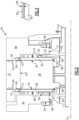
Figure 2 is cross-sectional view of a portion of the example rotary engine embodiment. -
Figure 3 is a cross-sectional view of an example anti-fretting coating applied to an example aluminum component. -
Figure 4 is a perspective view of an example main rotor housing embodiment. -
Figure 5 is a perspective view of an example side housing embodiment. -
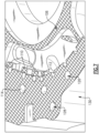
Figure 6 is an enlarged perspective view of a portion of the main rotor housing. -
Figure 7 is enlarged perspective view of a portion of an example side housing. -
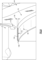
Figure 8 is sectional view of a portion of an example side housing. -
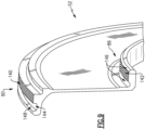
Figure 9 is a sectional view of a portion of an example transfer housing embodiment. -
Figure 10 is a sectional view of a portion of an example bearing support area of the side housing. - Referring to
Figures 1 and2 , a rotary internal combustion engine is schematically shown and indicated at 20. Theexample engine 20 includes an anti-fretting coating on select interface surfaces of aluminum alloy housing components to increase durability and long term wear resistance. - The example rotary
internal combustion engine 20 is commonly referred to as a Wankel engine and includes arotor 26 that rotates within arotor cavity 28 defined by aperipheral wall 24 of amain rotor housing 22. Therotor 26 oscillates about an engine central axisA. Coolant passages 30 are defined within theperipheral wall 24 for circulation of a cooling flow. Aninlet 40 and exhaust 42 are indicated schematically and provide communication of fuel and exhaust gases with therotor cavity 28. - The
rotor 26 includessides 34 that extend between threeapex portions 32. Anend seal 38 andapex seal 36 are disposed at each of theapex portions 32. Theapex seal 36 provides for sealing against theperipheral wall 24 and theend seal 38 provides for sealing against aseal running surface 45 on each of afirst side plate 48 and a second side plate 50 (Figure 2 ). In one example embodiment, thefirst side plate 48 and thesecond side plate 50 are formed from a silicon carbide material. In another example embodiment, thefirst side plate 48 and thesecond side plate 50 are formed from an aluminum material. Theside plates - A
first side housing 44 is attached at afirst interface 60 to a first side of themain rotor housing 22. Asecond side housing 46 is attached at a second interface (62) to a second side of themain rotor housing 22. Thefirst side plate 48 includes anedge 76 that is disposed within afirst clearance space 64 between aninner edge 72 of thefirst side housing 44 and themain housing 22. Thesecond side plate 50 includes anedge 78 that is disposed within aclearance space 66 between themain housing 22 and an inner edge 74 of thesecond side housing 46. The first andsecond side plates rotor cavity 28 such thatrotor 26 is mounted with an axial clearance betweenside plates side plates second interfaces - The first and
second side plates first transfer housing 52 and asecond transfer housing 54. The first andsecond transfer housings second side housings first transfer housing 52 mates to thefirst side housing 44 at a radiallyinner interface 90. Thesecond transfer housing 54 mates to thesecond side housing 44 at a radiallyinner interface 92. - A first
main bearing support 56 is in contact with thefirst housing 44 at aradial interface 98 and anaxial interface 94. A secondmain bearing support 58 is in contact with thesecond side housing 46 at aradial interface 100 and anaxial interface 96. In one disclosed example, the firstmain bearing support 56 and thesecond bearing support 52 are steel parts. - Select interfaces between the components are treated with an anti-fretting coating. The anti-fretting coating is applied to component interfaces and provide increased wear resistance.
- Referring to
Figure 3 with continued reference toFigure 2 , anexample surface 82 is shown with ananti-fretting coating 80. Theanti-fretting coating 80 is applied to athickness 84. Thethickness 84 is determined to provide the desired increases in wear resistances and durability without interfering with component assembly and fitment. The specific material composition of the anti-fretting coating may vary depending on the location and is tailored to provide wear resistance for that location. In one example embodiment, the anti-fretting coating comprises an aluminum bronze thermal spray. In another example embodiment, the anti-fretting coating includes chromium carbide or tungsten carbide. The anti-fretting coating may be machined to a final desired thickness and may be applied to thethickness 84 that corresponds with capabilities of a specific coating process. - Additionally, the example anti-fretting coating is selected from material that is compatible with strains encountered at each interface. Accordingly, the composition of the anti-fretting coating is selected, at least partially, based on a ductility in view of the local strain at any interface. Additionally, the
example anti-fretting coating 80 is applied as a single-layer coating. However, a multi-layer coating could also be used and is within the contemplation and scope of this disclosure. - Referring to
Figures 4 and5 , with continued reference toFigure 2 , themain rotor housing 22 includessurface 102 of theinterface 60 with thefirst side housing 44. Thefirst side housing 44 is shown by way of example and the similar configuration is provided between themain housing 22 and the second side housing at theinterface 62. - The
interface 60 is between thesurface 102 of themain housing 22 and thesurface 104 of thefirst side housing 44. Either or bothsurfaces side housing 44 are coated with an anti-fretting coating indicated at 108. - Referring to
Figure 6 with continued reference toFigure 4 , a portion of themain rotor housing 22 is shown and includes thesurface 102 of thefirst interface 60. Themain rotor housing 22 includes dowel holes 118, fastener holes 116 and other holes for cooling. Aseal groove 120 is disposed at an inner portion and anouter seal groove 124. The seal groove provides a location for an O-ring or other seal assembly. Theseal groove 120 may be masked to prevent coating deposition in this area. The dowel holes 118 are masked to prevent impingement of anti-fretting coating. The dowel holes 118 are held to a tight tolerance and therefore are masked to block errant application of the anti-fretting coating. Moreover, theseal groove 124 may also be masked to prevent disruption of the sealing functions. The fastener holes 116 may be permitted to include overspray of the anti-fretting coating as any such coating would have negligible effect on cooling flow. Moreover, an interior surface indicated at 122 may be allowed to be open to overspray of the anti-fretting coating if a final machining operation of the coating is utilized after application of the coating. Accordingly, no residual coating or overspray is left on the completed part, but is allowed prior to finish machining operations that would remove such residual coating. - Referring to
Figure 7 , with continued reference toFigure 5 , a portion of theside housing 44 is shown and includes aplate support surface 106 is stepped down from thesurface 104 of theside housing 44. Each of thefirst side housing 44 and thesecond side housing 44 include aplate support surface 106 that abuts a corresponding one of thefirst side plate 48 and thesecond side plate 50. Theplate support surface 106 includes an anti-fretting coating. Theplate support surface 106 abuts thefirst side plate 48 and includes an anti-fretting coating indicated by thecross-hatching 108. It should be appreciated that corresponding support surfaces are present in thesecond side housing 46 and would be similarly coated. - The
support surface 106 is interrupted atportions 110 by a plurality ofchannels 112. Theportions 110 are coated along with thesupport surface 106 to increase wear resistance at the interface with theside plate 48. - A
dowel hole 128 is masked to prevent overspray impingement and to maintain the desired dimensions.Holes channels 112 may be allowed to have some overspray of the anti-fretting coating. Anexterior surface 130 may also be permitted to accumulate some overspray. The surfaces that can tolerate overspray of the anti-fretting coating are not masked to simplify application of the anti-fretting coating. - The application of the anti-fretting coating may be completed before any final contour machining of all these
channels 112 to simplify the coating process and avoid complex masking. For example, a simple pocket having the depth of the side plate back support face could be machined in the semi-finish side housing, then the coating would be applied and final machined to produce all the support face contours and improve the surface finish and flatness of the coating surface on the remaining coated surfaces. - Referring to
Figure 8 , theside housing 44 portion of theinterface 90 is shown and includes an innerradial face surface 132 that has ananti-fretting coating 134 deposited within arecess 136. The innerradial face surface 132 of each of thefirst side housing 44 and thesecond side housing 46 is recessed to accommodate a thickness of the anti-fretting coating. Theanti-fretting coating 134 is applied inside therecess 136 in thebore surface 132 that is pre-machined in theside housing 44. A transition chamfer orradius 138 may be formed after application of theanti-fretting coating 134. An adjacent axial face is theinterface 70 between theside housing 44 and theseal plate 48. A blow-by-hole 168 and aseal groove 170 are shown and are masked to prevent built up of any coating in the indicated areas. - Referring to
Figure 9 with continued reference toFigure 2 , thefirst transfer housing 52 is shown in cross-section and includescoated surface 140 of the interface 90 (Figure 2 ). Thefirst transfer housing 52 further includescoated surface 142 of theinterface 86. Both thefirst transfer housing 52, shown inFigure 9 and thesecond transfer housing 54 include the radiallyouter surface 140 abutting a corresponding radial face surface 132 (Figure 8 ) of the corresponding one of thefirst side housing 44 and thesecond side housing 46. Theradial face surface 140 includes the anti-fretting coating. - Each of the
first transfer housing 52 and thesecond transfer housing 54 includes a radiallyinner surface 142 abutting a radiallyinner surface 86, 88 (Figure 2 ) of a corresponding one of thefirst side plate 48 and thesecond side plate 50. - The radially
inner surface 142 is coated with anti-fretting coating and is disposed betweenchamfers 146. Thetransfer housing 52 is made of aluminum alloy and the coating is applied to protect the aluminum of both theside housing 44 and thetransfer housing 52. At theinterface 86, the anti-fretting coating is applied to prevent direct contact between the aluminum alloy of thetransfer housing 52 andside plate 48 and therefore protect both parts. Overspray may be permitted on theadjacent chamfers 146 disposed on either side of the radiallyinner surface 142. Aseal groove 148 incudes aninner side 144 that may have overspray. Overspray on theinner side 144 of the seal groove may be allowed because the remainder of theseal groove 148 remains clear of overspray. - Referring to
Figure 10 , a portion of thefirst side housing 44 that abuts against the first main bearing support 56 (Figure 1 ). The firstmain bearing support 56 is a steel part and therefore a coating is applied to portions of theside housing 44 in contact with the steel main bearing support. Theside housing 44 engages the steelmain bearing support 56 at theinterfaces main bearing support 56 will tend to wear thealuminum side housing 44. Accordingly, coated surfaces 148 and 150 ofrespective interfaces aluminum side housing 44. The bore of theside housing 44 includes aseal groove 162 that is masked within the spacing indicated at 164. - A
chamfer 166 leading into theseal groove 162 may be permitted some overspray. The overspray on thechamfer 166 may be smoothed to ease the transition into theseal groove 162. Theinner diameter 154 of an opening is masked to prevent adhesion of overspray. Thechamfer 156 leading into theinner diameter 154 of thread hole is not masked to ease operation. Similarly, theinner diameter 158 is masked while thechamfer 160 transitioning into theinner diameter 158 is allowed to have some overspray of anti-fretting coating. Ashoulder pin hole 152 is masked to prevent anti-fretting coating from changing a defined fit between a shoulder pin (not shown) and thehole 152. Although the portion of thefirst side housing 44 that engages thefirst bearing support 56 is shown and describe by way of example, thesecond side housing 46 would include the same or similar surfaces that are engaged to the second main bearing support 58 (Figure 1 ). - Although the example anti-fretting coating is described and disclosed by example as being a compound applied in a thermal spray process, other coating application processes could be utilized and are within the contemplation of this disclosure.
- For example, a hard anodizing treatment could be utilized and applied to both the
side housings main rotor housing 22. All surfaces and locations could be protected in the same operation and may provide reduced costs and manufacturing efforts. - Additionally, a hard carbon coating could be utilized instead of thermal deposition or anodizing. A hydrogen free amorphous carbon coating may be applied to aluminum alloys using a filtered arc technique.
- Furthermore, an electro-deposited coating may be applied to protect selected locations. Many alternatives exist such as Ni-based matrix with fine SiC particles, Co-based matrix with chromium carbide particles, Co-P (pure, with chromium carbide or SiC particles). In this process, the part is immerged in an electrolyte bath and an electrical current is circulated between the parts (cathode) and a metalizing source material (anode).
- Alternatively, a doped aluminum powder deposition process could be utilized. In such a process, a thin layer of aluminum alloy reinforced with hard particles such as SiC is applied in a process similar to thermal deposition.
- Accordingly, the example disclosed housing provides for the localized application of an anti-fretting coating to significantly reduce or eliminate wear and fretting damage at the highly loaded mechanical interfaces of the rotary engine. Such wear is reduced while still providing for use of lightweight aluminum housing designs to meet aerospace demanding power-to-weight ratio targets.
- A rotary internal combustion engine according to an aspect of the present invention includes, among other possible things, a
main rotor housing 22 that has aperipheral wall 24 that circumscribes arotor cavity 28, a first interface surface and a second interface surface. Arotor 26 is disposed within therotor cavity 28. Afirst side housing 44 is secured against the first interface surface of themain rotor housing 22. Asecond side housing 46 is secured against the second interface surface of themain rotor housing 22, themain rotor housing 22, thefirst side housing 44 and thesecond side housing 46 are formed from an aluminum alloy and at least one of the first interface surface and the second interface surface include an anti-fretting coating. Afirst side plate 48 is partially disposed within aclearance space first side housing 44 and the main housing. Asecond side plate 48/50 is partially within aclearance space 64/66 that is disposed between thesecond side housing 46 and the main housing. Each of thefirst side plate 48 and thesecond side plate 48/50 define a runningsurface 45 for therotor 26. - In an embodiment according to the above aspect, each of the
first side housing 44 and thesecond side housing 46 include aplate support surface 106 that abuts a corresponding one of thefirst side plate 48 and thesecond side plate 48/50 and theplate support surface 106 includes an anti-fretting coating. - In an embodiment according to any of the above aspects or embodiments, each of the
first side housing 44 and thesecond side housing 46 includes a peripheral surface that abuts a corresponding one of thefirst side plate 48 and thesecond side plate 48/50 and the peripheral surface includes an anti-fretting coating. - In an embodiment according to any of the above aspects or embodiments, the rotary internal combustion engine includes a
first transfer housing 52 and asecond transfer housing 54 that each includes a radiallyouter surface 140 that abuts a corresponding innerradial face surface 132 of one of thefirst side housing 44 and thesecond side housing 46. Theradial face surface 132 includes an anti-fretting coating. - In an embodiment according to any of the above aspects or embodiments, the
radial face surface 132 of each of thefirst side housing 44 and thesecond side housing 46 is recessed to accommodate a thickness of the anti-fretting coating. - In an embodiment according to any of the above aspects or embodiments, each of the
first transfer housing 52 and thesecond transfer housing 54 includes a radiallyinner surface 142 that abuts a radiallyinner surface 142 of a corresponding one of thefirst side plate 48 and thesecond side plate 48/50 and the radiallyinner surface 142 includes an anti-fretting coating. - In an embodiment according to any of the above aspects or embodiments, each of the
first transfer housing 52 and thesecond transfer housing 54 include a seal surface adjacent to the radiallyinner surface 142 that does not include the anti-fretting coating. - In an embodiment according to any of the above aspects or embodiments, the rotary internal combustion engine further includes a
first bearing support 56 and asecond bearing support 58 that abut against an inner bore surface of a corresponding one of thefirst side housing 44 and thesecond side housing 46. The inner bore surface of each of thefirst side housing 44 and thesecond side housing 46 includes an anti-fretting coating. - In an embodiment according to any of the above aspects or embodiments, the anti-fretting coating includes a thermal spray coating that contains at least one of a chromium carbide, aluminum bronze, or tungsten carbide.
- In an embodiment according to any of the above aspects or embodiments, the anti-fretting coating includes one of an anodizing coating, a hard carbon coating, an electro-deposition coating or an aluminum powder coating.
- In an embodiment according to any of the above aspects or embodiments, the anti-fretting coating is machined to a desired thickness.
- In an embodiment according to any of the above aspects or embodiments, the rotary internal combustion engine includes a
first transfer housing 52 and asecond transfer housing 54 that each includes a radiallyouter surface 140 that abuts a correspondingradial face surface 132 of one of thefirst side housing 44 and thesecond side housing 46 and a radiallyinner surface 142 that abuts a radiallyinner surface 142 of a corresponding one of thefirst side plate 48 and thesecond side plate 48/50. Both the radiallyouter surface 140 and theradial face surface 132 include the anti-fretting coating. - In an embodiment according to any of the above aspects or embodiments, at least one of the anti-fretting coatings of any of the above includes a thermal spray coating that contains at least one of a chromium carbide, aluminum bronze, or tungsten carbide. The at least one of the anti-fretting coatings may thus be any of the anti-fretting coatings of: the inner bore surface, the radially
inner surface 142 of thefirst transfer housing 52 and/orsecond transfer housing 54, the radiallyouter surface 140, the innerradial face surface 132, the peripheral surface, theplate support surface 106, thefirst interface surface 60, and/or thesecond interface surface 62. - In an embodiment according to any of the above aspects or embodiments, at least one of the anti-fretting coatings of any of the above includes one of an anodizing coating, a hard carbon coating, an electro-deposition coating or an aluminum powder coating. The at least one of the anti-fretting coatings may thus be any of the anti-fretting coatings of: the inner bore surface, the radially
inner surface 142 of thefirst transfer housing 52 and/orsecond transfer housing 54, the radiallyouter surface 140, the innerradial face surface 132, the peripheral surface, theplate support surface 106, thefirst interface surface 60, and/or thesecond interface surface 62. - In an embodiment according to any of the above aspects or embodiments, at least one of the anti-fretting coatings of any of the above is machined to a desired thickness. The at least one of the anti-fretting coatings may thus be any of the anti-fretting coatings of: the inner bore surface, the radially
inner surface 142 of thefirst transfer housing 52 and/orsecond transfer housing 54, the radiallyouter surface 140, the innerradial face surface 132, the peripheral surface, theplate support surface 106, thefirst interface surface 60, and/or thesecond interface surface 62. - A rotary internal combustion engine according to another aspect of the present invention includes, among other possible things, a
main rotor housing 22 that has aperipheral wall 24 that circumscribes arotor cavity 28, a first interface surface and a second interface surface. Arotor 26 is disposed within therotor cavity 28. Afirst side housing 44 is secured against the first interface surface of themain rotor housing 22. Asecond side housing 46 is secured against the second interface surface of themain rotor housing 22, themain rotor housing 22, thefirst side housing 44 and thesecond side housing 46 are formed from an aluminum alloy and at least one of the first interface surface and the second interface surface include an anti-fretting coating that has chromium carbide. Afirst side plate 48 is partially disposed within aclearance space 64/66 between thefirst side housing 44 and the main housing. Asecond side plate 48/50 is partially within aclearance space 64/66 that is disposed between thesecond side housing 46 and the main housing. Each of thefirst side plate 48 and thesecond side plate 48/50 define a runningsurface 45 for therotor 26, each of thefirst side housing 44 and thesecond side housing 46 include aplate support surface 106 and an inner peripheral shoulder that have a peripheral surface that abuts a corresponding one of thefirst side plate 48 and thesecond side plate 48/50 and both theplate support surface 106 and the peripheral surface include the anti-fretting coating. - In an embodiment according to any of the above aspects or embodiments, the rotary internal combustion engine includes a
first transfer housing 52 and asecond transfer housing 54 that each includes a radiallyouter surface 140 that abuts a correspondingradial face surface 132 of one of thefirst side housing 44 and thesecond side housing 46 and a radiallyinner surface 142 that abuts a radiallyinner surface 142 of a corresponding one of thefirst side plate 48 and thesecond side plate 48/50. Both the radiallyouter surface 140 and theradial face surface 132 include the anti-fretting coating. - In an embodiment according to any of the above aspects or embodiments, the rotary internal combustion engine further includes a
first bearing support 56 and asecond bearing support 52 that abut against an inner bore surface of a corresponding one of thefirst side housing 44 and thesecond side housing 46. The inner bore surface of at least one of thefirst side housing 44 and thesecond side housing 46 includes an anti-fretting coating. - A method of assembling a rotary internal combustion engine according to another aspect of the present invention includes, among other possible things, forming at least a
main rotor housing 22, afirst side housing 44 and asecond side housing 46 from an aluminum alloy. Afirst side plate 48 and asecond side plate 48/50 are formed. Interface surfaces are selected between at least themain rotor housing 22, thefirst side housing 44, thesecond side housing 46, thefirst side plate 48 and thesecond side plate 48/50. Non-selected surface of the each of the at least themain rotor housing 22, thefirst side housing 44, thesecond side housing 46, thefirst side plate 48 and thesecond side plate 48/50 are masked. An anti-fretting coating is applied to the selected interface surfaces. - In an embodiment according to any of the above aspects or embodiments, the method further includes forming a
recess 136 on at least one of the selected interface surfaces prior to application of the anti-fretting coating. Therecess 136 is formed to correspond with a final thickness of the anti-fretting coating. - In an embodiment according to any of the above aspects or embodiments, the method further includes applying the anti-fretting coating to first thickness and machining the anti-fretting coating to a second thickness that is less than the first thickness.
- In an embodiment according to any of the above aspects or embodiments, the method further includes selecting a radially
outer surface 140 on each of afirst transfer housing 52 and asecond transfer housing 54 that abuts a correspondingradial face surface 132 of one of thefirst side housing 44 and thesecond side housing 46 and applying the anti-fretting coating to the radiallyouter surface 140. - In an embodiment according to any of the above aspects or embodiments, each of the
first transfer housing 52 and thesecond transfer housing 54 include a seal surface adjacent to the radiallyinner surface 142 and the method includes the step of masking the seal surface. - In an embodiment according to any of the above aspects or embodiments, the anti-fretting coating of any of the above includes one of a chromium carbide, an aluminum bronze, or a tungsten carbide. The anti-fretting may thus the be that applied to the selected interface surfaces and/or to the radially outer surface.
- Although an example embodiment has been disclosed, a worker of ordinary skill in this art would recognize that certain modifications would come within the scope of this disclosure. For that reason, the following claims should be studied to determine the scope and content of this disclosure.
Claims (15)
- A rotary internal combustion engine (20) comprising:a main rotor housing (22) having a peripheral wall (24) circumscribing a rotor cavity (28), a first interface surface (60) and a second interface surface (62);a rotor (26) disposed within the rotor cavity (28);a first side housing (44) secured against the first interface surface (60) of the main rotor housing (22);a second side housing (46) secured against the second interface surface (62) of the main rotor housing (22), wherein the main rotor housing (22), the first side housing (44) and the second side housing (46) are formed from an aluminum alloy and at least one of the first interface surface (60) and the second interface surface (62) includes an anti-fretting coating (80;108);a first side plate (48) partially disposed within a clearance space (64) between the first side housing (44) and the main rotor housing (22); anda second side plate (50) partially within a clearance space (66) disposed between the second side housing (46) and the main rotor housing (22), wherein each of the first side plate (48) and the second side plate (50) define a running surface (45) for the rotor (26).
- The rotary internal combustion engine (20) as recited in claim 1, wherein:each of the first side housing (44) and the second side housing (46) include a plate support surface (106) that abuts a corresponding one of the first side plate (48) and the second side plate (50); andthe plate support surface (106) includes an anti-fretting coating.
- The rotary internal combustion engine (20) as recited in claim 1 or 2, wherein:each of the first side housing (44) and the second side housing (46) includes a peripheral surface abutting a corresponding one of the first side plate (48) and the second side plate (50); andthe peripheral surface includes an anti-fretting coating.
- The rotary internal combustion engine (20) as recited in any preceding claim, including a first transfer housing (52) and a second transfer housing (54) that each include a radially outer surface (140) abutting a corresponding inner radial face surface (132) of one of the first side housing (44) and the second side housing (46), wherein the inner radial face surface (132) includes an anti-fretting coating, optionally wherein:
both the radially outer surface (140) and the inner radial face surface (132) include an anti-fretting coating. - The rotary internal combustion engine (20) as recited in claim 4, wherein the inner radial face surface (132) of each of the first side housing (44) and the second side housing (46) is recessed to accommodate a thickness of the anti-fretting coating.
- The rotary internal combustion engine (20) as recited in claim 4 or 5, wherein:each of the first transfer housing (52) and the second transfer housing (54) include a radially inner surface (142) abutting a radially inner surface (86,88) of a corresponding one of the first side plate (48) and the second side plate (50); andthe radially inner surface (142) of the first transfer housing (52) and/or second transfer housing (54) includes an anti-fretting coating,optionally wherein:each of the first transfer housing (52) and the second transfer housing (54) include a seal surface adjacent to the radially inner surface (142) of the first transfer housing (52) and/or second transfer housing (54); andthe seal surface does not include the anti-fretting coating.
- The rotary internal combustion engine (20) as recited in any preceding claim, further including a first bearing support (56) and a second bearing support (58) that abut against an inner bore surface of a corresponding one of the first side housing (44) and the second side housing (46), wherein the inner bore surface of each of the first side housing (44) and the second side housing (46) includes an anti-fretting coating.
- The rotary internal combustion engine (20) as recited in any preceding claim, wherein at least one of the anti-fretting coatings comprises a thermal spray coating containing a chromium carbide, aluminum bronze, and/or tungsten carbide.
- The rotary internal combustion engine (20) a recited in any preceding claim, wherein at least one of the anti-fretting coatings comprises one of an anodizing coating, a hard carbon coating, an electro-deposition coating or an aluminum powder coating.
- The rotary internal combustion engine (20) as recited in any preceding claim, wherein at least one of the anti-fretting coatings is machined to a desired thickness.
- A method of assembling a rotary internal combustion engine (20) comprising:forming at least a main rotor housing (22), a first side housing (44) and a second side housing (46) from an aluminum alloy;forming a first side plate (48) and a second side plate (50); andselecting interface surfaces (60,62;102;104,106) between at least the main rotor housing (22), the first side housing (44), the second side housing (46), the first side plate (48) and the second side plate (50);masking a non-selected surface (120,124;170;162) of the each of the at least the main rotor housing (22), the first side housing (44), the second side housing (46), the first side plate (48) and the second side plate (50); andapplying an anti-fretting coating (80;108) to the selected interface surfaces (60; ... 106).
- The method as recited in claim 11, further comprising forming a recess on at least one of the selected interface surfaces (60... 106) prior to application of the anti-fretting coating (80;108), wherein the recess is formed to correspond with a final thickness of the anti-fretting coating (80;108).
- The method as recited in claim 11 or 12, further comprising applying the anti-fretting coating (80; 108) to first thickness and machining the anti-fretting coating (80; 108) to a second thickness that is less than the first thickness.
- The method as recited in claim 11, 12 or 13, further comprising selecting a radially outer surface (140) on each of a first transfer housing (52) and a second transfer housing (54) that abuts a corresponding inner radial face surface (132) of one of the first side housing (44) and the second side housing (46) and applying an or the anti-fretting coating to the radially outer surface (140), optionally wherein:
each of the first transfer housing (52) and the second transfer housing (54) include a seal surface adjacent to a radially inner surface (142) of the first transfer housing (52) and/or second transfer housing (54) and the method includes the step of masking the seal surface. - The method as recited in any of claims 11 to 14, wherein at least one of the anti-fretting coatings (80;108) comprises a chromium carbide, an aluminum bronze, or a tungsten carbide.
Applications Claiming Priority (1)
| Application Number | Priority Date | Filing Date | Title |
|---|---|---|---|
| US18/354,077 US12152490B1 (en) | 2023-07-18 | 2023-07-18 | Fretting resistant rotary engine housings |
Publications (1)
| Publication Number | Publication Date |
|---|---|
| EP4495378A1 true EP4495378A1 (en) | 2025-01-22 |
Family
ID=91953723
Family Applications (1)
| Application Number | Title | Priority Date | Filing Date |
|---|---|---|---|
| EP24188824.7A Pending EP4495378A1 (en) | 2023-07-18 | 2024-07-16 | Fretting resistant rotary engine housings |
Country Status (3)
| Country | Link |
|---|---|
| US (1) | US12152490B1 (en) |
| EP (1) | EP4495378A1 (en) |
| CA (1) | CA3270841A1 (en) |
Citations (5)
| Publication number | Priority date | Publication date | Assignee | Title |
|---|---|---|---|---|
| US20070099027A1 (en) * | 2005-10-28 | 2007-05-03 | Anand Krishnamurthy | Wear resistant coatings |
| EP1927670A1 (en) * | 2006-11-29 | 2008-06-04 | General Electric Company | Wear resistant coatings |
| US20200200009A1 (en) * | 2018-12-20 | 2020-06-25 | Pratt & Whitney Canada Corp. | Rotary engine with housing having silicon carbide plate |
| US20220280998A1 (en) * | 2021-03-03 | 2022-09-08 | General Electric Company | Anti-fretting coating composition and coated components |
| CA3153194A1 (en) * | 2021-03-23 | 2022-09-23 | Pratt & Whitney Canada Corp. | Side wall for rotary engine housing |
Family Cites Families (10)
| Publication number | Priority date | Publication date | Assignee | Title |
|---|---|---|---|---|
| US3155313A (en) * | 1962-10-01 | 1964-11-03 | Cuertiss Wright Corp | Rotor housing construction of rotating combustion engine |
| DE1451801A1 (en) * | 1965-03-10 | 1970-04-16 | Audi Nsu Auto Union Ag | Rotary piston internal combustion engine with a spray coating applied to the side parts or a method for spraying this spray coating |
| JPS5028250Y2 (en) * | 1971-06-29 | 1975-08-21 | ||
| DE2222632A1 (en) * | 1972-05-09 | 1973-11-22 | Daimler Benz Ag | ROTATING PISTON INTERNAL ENGINE |
| US3890069A (en) | 1973-07-05 | 1975-06-17 | Ford Motor Co | Coating for rotary engine rotor housings and method of making |
| US3833321A (en) | 1973-07-05 | 1974-09-03 | Ford Motor Co | Wear-resistant coating for rotary engine side housing and method of making |
| US3910734A (en) | 1973-08-20 | 1975-10-07 | Ford Motor Co | Composite apex seal |
| US3948309A (en) | 1973-08-20 | 1976-04-06 | Ford Motor Company | Composite rotor housing with wear-resistant coating |
| US3860367A (en) | 1973-08-24 | 1975-01-14 | Ford Motor Co | Controlled porous coating for rotary engine side housing |
| US10072566B2 (en) | 2015-12-18 | 2018-09-11 | Pratt & Whitney Canada Corp. | Rotary engine casing with seal engaging plate having mating surface defining a fluid cavity |
-
2023
- 2023-07-18 US US18/354,077 patent/US12152490B1/en active Active
-
2024
- 2024-06-17 CA CA3270841A patent/CA3270841A1/en active Pending
- 2024-07-16 EP EP24188824.7A patent/EP4495378A1/en active Pending
Patent Citations (5)
| Publication number | Priority date | Publication date | Assignee | Title |
|---|---|---|---|---|
| US20070099027A1 (en) * | 2005-10-28 | 2007-05-03 | Anand Krishnamurthy | Wear resistant coatings |
| EP1927670A1 (en) * | 2006-11-29 | 2008-06-04 | General Electric Company | Wear resistant coatings |
| US20200200009A1 (en) * | 2018-12-20 | 2020-06-25 | Pratt & Whitney Canada Corp. | Rotary engine with housing having silicon carbide plate |
| US20220280998A1 (en) * | 2021-03-03 | 2022-09-08 | General Electric Company | Anti-fretting coating composition and coated components |
| CA3153194A1 (en) * | 2021-03-23 | 2022-09-23 | Pratt & Whitney Canada Corp. | Side wall for rotary engine housing |
Non-Patent Citations (1)
| Title |
|---|
| MICHAEL J NEALE: "The Tribology Handboook (Second Edition)", REFEREX, 1973 - 1995, XP040425270, ISBN: 0 7506 1198 7 * |
Also Published As
| Publication number | Publication date |
|---|---|
| CA3270841A1 (en) | 2025-05-12 |
| US20250075622A1 (en) | 2025-03-06 |
| US12152490B1 (en) | 2024-11-26 |
Similar Documents
| Publication | Publication Date | Title |
|---|---|---|
| EP2578720B1 (en) | Repair methods for cooled components | |
| EP2613015B1 (en) | Hybrid blade outer air seal for a gas turbine engine | |
| EP2487330B1 (en) | Components with cooling channels and methods of manufacture | |
| US11333068B1 (en) | Side wall for rotary engine housing | |
| JP2911003B2 (en) | Engine sleeve | |
| US20120243995A1 (en) | Components with cooling channels formed in coating and methods of manufacture | |
| US20030150419A1 (en) | Piston having ceramic-coated ring groove | |
| US10837399B2 (en) | Method of manufacturing internal combustion engine, internal combustion engine, and connected cylinder | |
| EP1006218A2 (en) | Plated metal part and method of manufacturing same | |
| JPH11509893A (en) | Products with metal body | |
| US5794943A (en) | Piston rings particularly suited for use with ceramic matrix composite pistons and cylinders | |
| EP3421732B1 (en) | Turbine engine seal for high erosion environment | |
| US12152490B1 (en) | Fretting resistant rotary engine housings | |
| US3890069A (en) | Coating for rotary engine rotor housings and method of making | |
| EP4215780B1 (en) | Carbon face seal | |
| US6606983B2 (en) | Ferrous pistons for diesel engines having EGR coating | |
| JPS634056A (en) | Floating bearing of turbo charger | |
| US11098674B2 (en) | Piston for a heat engine, heat engine comprising such a piston, and methods | |
| US20060220322A1 (en) | Replenishment pockets on piston rings for the prevention of microwelding | |
| CN109882306A (en) | A modified structure for the inner wall of the cylinder | |
| Strangman | Thermal strain-tolerant Abradable thermal barrier coatings | |
| US12203410B1 (en) | Housing assembly for rotary engine | |
| JP2008138242A (en) | Abrasion resistant coating and article having the abrasion resistant coating | |
| US4106977A (en) | Process for production of oil control rings | |
| James et al. | Surface treatments in engine component technology |
Legal Events
| Date | Code | Title | Description |
|---|---|---|---|
| PUAI | Public reference made under article 153(3) epc to a published international application that has entered the european phase |
Free format text: ORIGINAL CODE: 0009012 |
|
| STAA | Information on the status of an ep patent application or granted ep patent |
Free format text: STATUS: THE APPLICATION HAS BEEN PUBLISHED |
|
| AK | Designated contracting states |
Kind code of ref document: A1 Designated state(s): AL AT BE BG CH CY CZ DE DK EE ES FI FR GB GR HR HU IE IS IT LI LT LU LV MC ME MK MT NL NO PL PT RO RS SE SI SK SM TR |
|
| STAA | Information on the status of an ep patent application or granted ep patent |
Free format text: STATUS: REQUEST FOR EXAMINATION WAS MADE |
|
| 17P | Request for examination filed |
Effective date: 20250722 |
|
| STAA | Information on the status of an ep patent application or granted ep patent |
Free format text: STATUS: EXAMINATION IS IN PROGRESS |
|
| 17Q | First examination report despatched |
Effective date: 20251030 |