EP4495372A1 - Device for a roll-up cover installation - Google Patents
Device for a roll-up cover installation Download PDFInfo
- Publication number
- EP4495372A1 EP4495372A1 EP24188127.5A EP24188127A EP4495372A1 EP 4495372 A1 EP4495372 A1 EP 4495372A1 EP 24188127 A EP24188127 A EP 24188127A EP 4495372 A1 EP4495372 A1 EP 4495372A1
- Authority
- EP
- European Patent Office
- Prior art keywords
- casing
- tubular shaft
- electrical energy
- storage unit
- energy storage
- Prior art date
- Legal status (The legal status is an assumption and is not a legal conclusion. Google has not performed a legal analysis and makes no representation as to the accuracy of the status listed.)
- Granted
Links
Images

Classifications
-
- E—FIXED CONSTRUCTIONS
- E06—DOORS, WINDOWS, SHUTTERS, OR ROLLER BLINDS IN GENERAL; LADDERS
- E06B—FIXED OR MOVABLE CLOSURES FOR OPENINGS IN BUILDINGS, VEHICLES, FENCES OR LIKE ENCLOSURES IN GENERAL, e.g. DOORS, WINDOWS, BLINDS, GATES
- E06B9/00—Screening or protective devices for wall or similar openings, with or without operating or securing mechanisms; Closures of similar construction
- E06B9/56—Operating, guiding or securing devices or arrangements for roll-type closures; Spring drums; Tape drums; Counterweighting arrangements therefor
- E06B9/68—Operating devices or mechanisms, e.g. with electric drive
- E06B9/72—Operating devices or mechanisms, e.g. with electric drive comprising an electric motor positioned inside the roller
-
- E—FIXED CONSTRUCTIONS
- E06—DOORS, WINDOWS, SHUTTERS, OR ROLLER BLINDS IN GENERAL; LADDERS
- E06B—FIXED OR MOVABLE CLOSURES FOR OPENINGS IN BUILDINGS, VEHICLES, FENCES OR LIKE ENCLOSURES IN GENERAL, e.g. DOORS, WINDOWS, BLINDS, GATES
- E06B9/00—Screening or protective devices for wall or similar openings, with or without operating or securing mechanisms; Closures of similar construction
- E06B9/02—Shutters, movable grilles, or other safety closing devices, e.g. against burglary
- E06B9/08—Roll-type closures
- E06B9/11—Roller shutters
- E06B9/17—Parts or details of roller shutters, e.g. suspension devices, shutter boxes, wicket doors, ventilation openings
- E06B9/174—Bearings specially adapted therefor
-
- E—FIXED CONSTRUCTIONS
- E04—BUILDING
- E04F—FINISHING WORK ON BUILDINGS, e.g. STAIRS, FLOORS
- E04F10/00—Sunshades, e.g. Florentine blinds or jalousies; Outside screens; Awnings or baldachins
- E04F10/02—Sunshades, e.g. Florentine blinds or jalousies; Outside screens; Awnings or baldachins of flexible canopy materials, e.g. canvas ; Baldachins
- E04F10/06—Sunshades, e.g. Florentine blinds or jalousies; Outside screens; Awnings or baldachins of flexible canopy materials, e.g. canvas ; Baldachins comprising a roller-blind with means for holding the end away from a building
- E04F10/0611—Sunshades, e.g. Florentine blinds or jalousies; Outside screens; Awnings or baldachins of flexible canopy materials, e.g. canvas ; Baldachins comprising a roller-blind with means for holding the end away from a building with articulated arms supporting the movable end of the blind for deployment of the blind
-
- E—FIXED CONSTRUCTIONS
- E06—DOORS, WINDOWS, SHUTTERS, OR ROLLER BLINDS IN GENERAL; LADDERS
- E06B—FIXED OR MOVABLE CLOSURES FOR OPENINGS IN BUILDINGS, VEHICLES, FENCES OR LIKE ENCLOSURES IN GENERAL, e.g. DOORS, WINDOWS, BLINDS, GATES
- E06B9/00—Screening or protective devices for wall or similar openings, with or without operating or securing mechanisms; Closures of similar construction
- E06B9/24—Screens or other constructions affording protection against light, especially against sunshine; Similar screens for privacy or appearance; Slat blinds
- E06B2009/247—Electrically powered illumination
-
- E—FIXED CONSTRUCTIONS
- E06—DOORS, WINDOWS, SHUTTERS, OR ROLLER BLINDS IN GENERAL; LADDERS
- E06B—FIXED OR MOVABLE CLOSURES FOR OPENINGS IN BUILDINGS, VEHICLES, FENCES OR LIKE ENCLOSURES IN GENERAL, e.g. DOORS, WINDOWS, BLINDS, GATES
- E06B9/00—Screening or protective devices for wall or similar openings, with or without operating or securing mechanisms; Closures of similar construction
- E06B9/24—Screens or other constructions affording protection against light, especially against sunshine; Similar screens for privacy or appearance; Slat blinds
- E06B2009/2476—Solar cells
Definitions
- the present invention concerns a device configured and intended to be used and mounted in a roll-up cover installation.
- the present invention also concerns an apparatus, comprising said device, and configured and intended to be used and mounted in a roll-up cover installation.
- the present invention also concerns a roll-up cover installation including said device.
- the rigid crosspiece In the case of a cantilever awning, the rigid crosspiece is connected to the support structure of the tubular shaft via a pair of articulated arms, while in the case of a sliding awning, the rigid crosspiece is slid with its ends along two fixed parallel tracks located on the sides of the surface that must be coverable by the unfolded awning.
- the rigid crosspiece may have such a shape as to cover the awning, when it is wound around the tubular shaft, and to thus constitute a sort of protection box for the latter, which in this case is called a box awning.
- WO2019026032 requires, in order to replace the battery, to completely extract/remove the tubular casing of the device from the tubular shaft, around which the cover element is wound, so as to be able to thus have access to the side door of the tubular casing of the device itself.
- KR2010/0118723A discloses an automatic operating device for a roller awning, wherein the device comprises an internally hollow cylindrical container which is incorporated within the hollow winding/unwinding roller of the awning, a cylindrical case for a battery which is inserted into the inside of the cylindrical container, a motor, an element that connects the motor output with the winding/unwinding roller of the awning, an electric cable that connects the battery to the motor and an infrared receiving unit that controls the power supply of the motor.
- the object of the invention is to propose a device for a roll-up cover installation which allows to overcome, at least in part, the drawbacks found in known solutions.
- Another object of the invention is to propose a device that allows easy and rapid access to the components inside it even when the device itself is already installed.
- Another object of the invention is to propose a device which also acts as a lateral support for the shaft around which the cover element of the roll-up cover installation is wound/unwound.
- Another object of the invention is to propose a device that can also be used in combination with photovoltaic panels or other renewable energy sources.
- Another object of the invention is to propose a device with particularly small dimensions.
- Another object of the invention is to propose a device which can also be installed in conditions wherein the available spaces, particularly in length, are reduced.
- Another object of the invention is to propose a device that is simple and quick to install and maintain, even by non-specialized personnel,
- Another object of the invention is to propose a device that is structurally independent, autonomous and/or additional to the device provided for motorizing the roll-up cover installation.
- Another object of the invention is to propose an apparatus which supports the shaft, around which the cover element of the roll-up cover installation is wound/unwound, at both the mutually opposite longitudinal ends of the shaft itself and which, at the same time, it is simple and quick to install, as well as compact.
- Another object of the invention is to propose an apparatus that allows the electrical power supply of the engine and/or of other electrical users (such as for example lighting elements and/or an acoustic speaker) through the electrical energy of a storage unit of electrical energy which is housed and mounted inside the apparatus itself.
- Another object of the invention is to propose an apparatus wherein the electrical energy storage unit is easy and rapid to access from the outside, even when the apparatus itself is already installed.
- Another object of the invention is to propose an apparatus that allows the motor and/or other electrical users (such as for example lighting elements) to be powered in an eco-sustainable way.
- Another object of the invention is to propose a device or apparatus that is an improvement and/or alternative to traditional ones.
- Another object of the invention is to propose a device or apparatus which can be obtained in a simple, rapid and low-cost manner.
- Another object of the invention is to propose a roll-up cover installation which can be obtained in a simple, rapid and low-cost way, which is simple and quick to install and maintain, as well as eco-sustainable.
- the device according to the invention (indicated globally with the reference number 1) is applied/mounted, in the illustrated example, to a roll-up cover installation (indicated globally with the reference number 80).
- the roll-up cover installation 80 comprises a tubular shaft 82, which is actuated (preferably motorized) in rotation about its longitudinal development axis, and also comprises a cover element 86 which has a flap attached to the tubular shaft 82 and which, following the rotation of the tubular shaft 82, can be wound around said shaft and unwound from it.
- the device 1 is mounted inside the tubular shaft 82 at a first longitudinal end of said shaft 82.
- the roll-up cover installation 80 can be - from a structural point of view - of a traditional type.
- the roll-up cover installation 80 is of the roller type.
- the roll-up cover installation 80 is motorized but could also be moved manually.
- the roll-up cover installation 80 is of the type of cantilever roll-up awning with articulated arms, i.e. it is of the type wherein the cover element 86 is defined by a sheet, which is wound around the tubular shaft 82 and unwound from this, and the installation also includes an external support structure 84 to support the tubular shaft 82, a rigid crosspiece 88, to which the flap of the cover element 86 opposite to the one attached to the tubular shaft 82 is applied, and two pairs of articulated arms 89, which connect the rigid crosspiece 88 to the external support structure 84 and drive it in its translational movements with respect to the latter.
- the winding/unwinding of the cover element 86 can take place along a substantially vertical direction or along a direction more or less inclined with respect to the vertical.
- the winding/unwinding of the cover element 86 around the tubular shaft 82 can take place along lateral tracks for the element itself.
- the tubular shaft 82 is internally hollow and can have any cross section.
- the tubular shaft 82 can have a circular or polygonal section, for example hexagonal, octagonal or similar.
- the external support structure 84 can include a rigid band 87, which appropriately adheres to a fixed structure, for example to a wall of a building, and a pair of lateral brackets 85, preferably wing-shaped, which extend outwards from said rigid band and which suitably support the tubular shaft 82 at the ends.
- lighting elements 90 are mounted on the roll-up cover installation 80 and/or on the external fixed structure surrounding said installation.
- the lighting elements 90 can be mounted on any component of the roll-up cover installation 80 and in any position of these.
- the lighting elements 90 can be mounted on the external support structure 84 and/or on the rigid crosspiece 88 and/or on the tubular shaft 82 and/or even on the cover element 86.
- the lighting elements 90 are light sources and, preferably, are LED strips that define monochromatic and/or RGB light sources.
- the lighting elements 90 can be made up of at least one LED strip which includes a set of LED diodes, i.e. electronic components which emit light when powered by electricity.
- the LED diodes are fixed - preferably by welding - on a printed circuit board (PCB), which is preferably flexible, which performs the function of support and electrical connection.
- the LED diodes of the LED strip can be configured to emit monochromatic light or they can be of the RGB type.
- the roll-up cover installation 80 also includes means configured to cause rotation in both directions of the tubular shaft 82, thus allowing the cover element 86 to be rolled up and unrolled having a flap fixed to said shaft.
- a motorization device 92 can be inserted into the tubular shaft 82 to cause rotation of the shaft itself in both directions around its longitudinal development axis.
- this motorization device 92 is inserted inside the tubular shaft 82 at a second end of the shaft itself, i.e. at the end which is opposite to the first end of the tubular shaft 82 at which device 1 is inserted.
- the motorization device 92 comprises an electric motor.
- the motorization device 92 comprises a motor configured to provide rotary motion as an output.
- the motorization device 92 comprises a traditional tubular electric driving/pulling motor, preferably of a single-phase asynchronous type, inserted within the tubular shaft 82.
- the motorization device 92 comprises a command and control unit for said motor.
- the motorization device 92 includes a motor head which is suitably fixed with any known system to the support structure 84, preferably fixed to a lateral bracket 85 (for example wing-shaped or defined by a support side plate) of the latter.
- the motorization device 92 includes an output pinion to which a pulling adapter (pulley) 94 of the tubular shaft 82 is coupled.
- a non-pulled adapter can be provided in the vicinity of said motor head of the motorization device 92.
- means can be provided - which can be manually operated and actuated - which are configured to cause rotation in both directions of the tubular shaft 82.
- these means configured to cause rotation in both directions of the tubular shaft 82 can be constituted by a traditional hand-operated chain or winch.
- the device 1 Inside the tubular shaft 82 there is also inserted the device 1 according to the invention and, in particular, it is inserted at a first end of the tubular shaft 82.
- the device 1 is inserted and housed at one (first) longitudinal end of the tubular shaft 82, while at the other (second/opposite) longitudinal end of the shaft itself the motorization device 92 is inserted and housed.
- the device 1 is substantially independent and autonomous from a constructional and positioning point of view with respect to the motorization device 92 of the roll-up cover installation 80.
- the device 1 is configured to act as a support for the tubular shaft 82 at said first longitudinal end of said shaft.
- the motorization device 92 can also act as a support for the tubular shaft 82 at the second (opposite) longitudinal end of said shaft.
- the device 1 comprises a casing 28, preferably but not necessarily tubular in shape, which is removably inserted inside the tubular shaft 82.
- the casing 28 is inserted entirely or mostly inside the first end of the tubular shaft 82.
- the casing 28 can be made of plastic.
- the device 1 includes means 30 for constraining the casing 28 to said external support structure 84 of said installation 80.
- the means 30 for constraining the casing 28 to said external support structure 84 can be made of plastic.
- At least one electrical energy storage unit 26 is inserted and removably housed inside the casing 28.
- said at least one electrical energy storage unit 26 includes an electric battery.
- said at least one electric energy storage unit 26 comprises a rechargeable electric battery.
- said electric battery which is preferably rechargeable, can be of the traditional type.
- said electrical energy storage unit 26 includes at least one electrical connection cable 27 or 27' and 27" which protrudes from the casing 28 and which also protrudes from said means 30 to constrain the casing 28 to an external support structure 84.
- said at least one electrical energy storage unit 26 is electrically isolated from the casing 28 and from the means 30.
- said at least one electrical energy storage unit 26 is housed exclusively and only inside the casing 28.
- a battery charger device or other accessories for electrically recharging the electrical energy storage unit 26 can be housed inside the casing 28.
- the casing 28 there is exclusively and only housed said at least one electrical energy storage unit 26 and, possibly, a battery charger device or other accessories for electrically recharging of the electrical energy storage unit 26.
- no control unit is housed inside the casing 28.
- no processor, microprocessor or microcontroller is housed inside the casing 28.
- no wireless receiver is housed inside the casing 28.
- the casing 28 is configured (in terms of shape and/or size) to exclusively and only house said at least one electrical energy storage unit 26 and, possibly, a battery charging device or other accessories for electrically recharging the unit of electricity storage 26.
- the battery body 25 of said electrical energy storage unit 26 is entirely housed and inserted inside the casing 28.
- the battery body 25 of said electrical energy storage unit 26 can have a cylindrical, box-like shape or in any case any shape such that it can be entirely housed and inserted inside the casing 28.
- the body 25 of said electrical energy storage unit 26 can be placed or removably fixed and supported inside the casing 28.
- said electrical energy storage unit 26 comprises at least one electrical connection cable 27 or 27' and 27".
- said electrical energy storage unit 26 includes a single electrical connection cable 27 which is used and configured both for the transfer of electrical energy from external photovoltaic panels (or other sources of renewable energy) towards the storage unit 26 and for the transfer of electrical energy from the storage unit 26 towards the motorization device 92 and/or other electrical users, such as for example towards the lighting elements 90.
- the means 30 include a passage (through) opening 60 which is configured to allow the insertion and extraction of the battery body 25 of said electrical energy storage unit 26.
- said passage opening 60 is shaped and sized so as to allow a passthrough in both directions by the battery body 25 of said electrical energy storage unit 26.
- said through opening 60 can have any shape, even different with respect to the cross section of the battery body 25, while being such as to allow the passthrough for the insertion/extraction of the battery body 25 into/from the tubular casing 28.
- the passage opening 60 is also crossed (at least in part) by said at least one electric cable 27 or 27' and 27".
- said at least one electric cable 27 or 27' and 27" also comes out of the device 1 crossing said passage opening 60.
- said battery body 25 and said at least one electric cable 27 or 27' and 27" can pass through the same opening 60 of the means 30 from one side to the other.
- the means for constraining the casing 28 to said external support structure 84 comprise a head 30 which is associated with the external longitudinal end of the casing 28 to fix it to the external support structure 84.
- the head 30 is configured so that, when it is mechanically engaged with the casing 28, at least a portion of said head 30 protrudes from the casing itself.
- the head 30 makes the casing 28 integral/fixed (directly or indirectly through means 40) to the external support structure 84, thus supporting the tubular shaft 82 at one of its ends.
- the head 30 is mechanically removably attached to the outer longitudinal end of the casing 28.
- a closing element 68 can be associated with the internal longitudinal end of the casing 28, said closing element 68 which, preferably, can be shaped to support the battery body 25 inside the casing itself.
- the side walls of the casing 28 are devoid of doors or holes for the passage of said at least one electrical connection cable 27 or 27' and 27" and/or of the battery body 25 of the electrical energy storage unit 26.
- said device 1 can include a first cap 61 to close said passage opening 60 once the battery body 25 of said electrical energy storage unit 26 has been inserted inside the casing 28.
- said first cap 61 can include at least one hole 65 for the passage of said at least one electrical connection cable 27 or 27' and 27".
- the head 30 is fixed directly or indirectly to a lateral bracket 85 which, in turn, can advantageously include a further passage opening 62 which is configured to allow the insertion and extraction of the battery body 25 of said electrical energy storage unit 26.
- said further passage opening 62 can have a shape and/or dimensions which are the same as or even different from those of the passage opening 60 of the head 30.
- said further passage opening 62 of the lateral bracket 85 faces the passage opening 60 of the head 30, to thus allow the insertion/extraction of the electrical energy storage unit 26 into/from the casing 28 without removing the device 1 from the shaft tubular 82 and also without having to remove the lateral bracket 85.
- a further cap (not shown) can be provided to close from the outside said further passage opening 62 of the lateral bracket 85.
- the head 30 can also include at least one section 64 for the passage of at least one electrical connection cable 27 or 27' and 27".
- said at least one section 64 is in communication with the passage opening 60 and is obtained on a portion of said head 30 that protrudes from the casing 28.
- said at least one passage section 64 of said at least one electric cable 27 or 27' and 27' comprises at least one through notch obtained on the head portion 30 which protrudes from the casing 28.
- said at least one through notch develops radially with respect to the passage opening 60 which is obtained centrally on the head 30.
- said at least one electric cable 27 or 27' and 27' of the electrical energy storage unit 60 comes out of the casing 28 first crossing the passage opening 60 obtained on the head 30 and then the section 64, which is also obtained on the head 30.
- said at least one section 64 can be configured so as to clamp or drive said at least one electric cable 27, to thus direct its exit direction from the device 1.
- the device 1 includes means 24 for idly supporting the tubular shaft 82, i.e. in such a way as to decouple the rotation of the tubular shaft 82 from the casing 28.
- said means 24 are configured to allow the casing 28 and/or said head 30 to support said tubular shaft 82 in an idle manner, i.e. in such a way as to decouple the rotation of the tubular shaft 82 from the casing 28 and from the head 30, thus allowing said tubular shaft 82 to rotate around its longitudinal development axis while the casing 28 and the head 30 remain fixed.
- the shape and dimensions of the casing 28 are not linked to those of the tubular shaft 82 although they must evidently be compatible with them.
- the casing 28 has a shape and dimensions suitable to allow its insertion and housing inside the tubular shaft 82.
- the stability of the positioning of the casing 28 inside the tubular shaft 82 can be obtained by said means 24.
- said means 24 for idly supporting the tubular shaft 82 can be mounted on said casing 28 and/or are mounted on said head 30.
- said means 24 for idly supporting the tubular shaft 82 can be placed between said casing 28 and tubular shaft 82 and/or can be placed between said head 30 and tubular shaft 82.
- the means 24 can be placed between said casing 28 and the tubular shaft 82 and can include at least one adapter which is precisely placed between the casing 28 and the tubular shaft 82 and which is configured to rotate with said tubular shaft 82 and to allow the casing 28 to idly support the tubular shaft 82.
- a pair of support adapters can be provided, interposed between the opposite sides of the casing 28 and the tubular shaft 82.
- a pair of support adapters is provided, spaced apart from each other, and positioned so that a first adapter is positioned or in any case is closer to the innermost end of the casing 28, while a second adapter is positioned or in any case is closer to the outermost end of the casing 28.
- said at least one adapter is of the non-pulled type and, in particular, they are mounted idly on the casing 28, that is, in such a way as to decouple the rotation of the tubular shaft 82 from the casing 28, thus allowing said shaft 82 to rotate around its longitudinal development axis while the casing 28 remains fixed/stationary.
- both the head 30 and the adapters of the device 1 have a shape similar respectively to that of the corresponding head and the corresponding adapters of the motorization device 92, but unlike those they have the sole function of idle support of the tubular shaft 82 at its end opposite to that of insertion of the motorization device 92.
- the casing 28 of the control device can be the same (in terms of shape and dimensions) as the corresponding casing of the motorization device 92.
- the means 24 can be interposed between the head 30 and the tubular shaft 82 and can include at least one adapter which is interposed between the head 30 and the tubular shaft 82 and which is configured to rotate with said tubular shaft 82 and to allow the head 30 to idly support the tubular shaft 82.
- the head 30 can support the tubular shaft 82 on its own so that the latter can rotate with respect to said head.
- said tubular casing 28 can be mounted on said head 30 so as to be supported exclusively by the head itself.
- the means 24 comprise a rotating element 31 which is mounted in an idle manner on the head 30 and which is intended to be integral in rotation with the tubular shaft 82.
- the element 31 is rotating with respect to the remaining fixed part of the head and supports, possibly by means of an adapter (not shown), the tubular shaft 82 at one of its ends.
- a rotating element 31 is mounted, preferably of an annular shape, which is made integral in rotation with the tubular shaft 82 and which rotates with respect to the fixed body said head.
- an adapter for mounting the tubular shaft 82 is then mounted on the rotating element 31.
- an adapter to support the shaft itself is interposed between the rotating element 31 mounted on the head 30 and the tubular shaft 82.
- the rotating element 31 supports the adapter which thus allows coupling with the various shapes of the cross section of the shaft 82.
- the rotating element 31 is the only element of the device 1 which, through the adapter, supports the tubular shaft 82.
- the casing 28 can be configured to attach in a removable manner to the head 30, in particular to an internal portion 33 of the head 30.
- said tubular casing 28 is attached, preferably by means of clip coupling means, to the head 30.
- an internal portion 33 of the head 30 is inserted into the casing 28 and these are then fixed to each other by means of a traditional first mechanical locking member 34 (for example a screw or a grub screw).
- a traditional first mechanical locking member 34 for example a screw or a grub screw.
- the casing 28 and the internal portion 33 of the head 30 which fits into the casing are provided with mutual engagement means, defined for example by protruding sections and hollow/holed counter-sections, to thus prevent the movement of the casing with respect to the head 30, while the engagement defined by said first locking member 34 prevents the longitudinal extraction/movement of the casing 28 with respect to the head 30.
- the device 1 can include means 40 for fixing the head 30 to the lateral bracket 85, which can be shaped like a wing (see fig. 2 ) or which can be defined by a side plate (see fig. 5 and 6 ), of the external support structure 84.
- said fixing means 40 can include at least two elements 41' and 41" which laterally clamp an external portion 35 (i.e. a portion that remains outside the casing 28) of the head 30.
- the fixing means 40 can comprise at least two elements - 41' and 41" respectively - which laterally clamp an external portion 35 (i.e. the one destined to always remain outside the tubular shaft 82) of the head 30.
- at least a first clamping element 41' can be configured so as to be fixed to the lateral bracket 85, preferably by means of second mechanical locking members 36 (for example screws or bolts with corresponding nuts), while the another (second) clamping member 41" is configured to be fixed to the first clamping element 41', to thus wrap externally - at least in part - the external portion 35 of the head 30.
- said elements 41', 41" clamp the external portion 35 of the head 30 so as to prevent the latter (with the corresponding casing 28 associated with it) - once clamped - from translating longitudinally (i.e. along an X axis which is substantially corresponding or parallel to the longitudinal axis of the casing 28 or of the tubular shaft 82) or laterally (i.e. along a direction perpendicular to the X axis), or rotating about the X axis. Therefore, when constraining the clamping elements 41', 41" to the lateral bracket 85, the head 30 also is thus fixed to said bracket 85.
- clamping elements 41' and 41" once arranged in sequence around the external portion 35 of the head 30, are fixed to each other by means of third fixing members 37 (for example screws).
- the external portion 35 of the head 30 defines a profile that is substantially complementary, or at least partly complementary, to that internally delimited by the internal surfaces of the clamping elements 41' and 41".
- the external portion 35 of the head 30 defines a shaped profile/section which engages by interlocking with a profile/section defined on the internal surfaces of the clamping elements 41' and 41".
- the head 30 can include a circumferential flange 42 which separates the external portion 35 from the remaining part of the head itself and, in particular, from the internal portion 33.
- the circumferential flange 42 is intended to rest frontally on the clamping elements 41' and 41", once the external portion 35 of the state 30 has been enclosed/embraced between them
- the external portion 35 of the head 30 is also shaped so that it can be inserted frontally (i.e. along an insertion direction substantially corresponding to or parallel to the X axis), to thus make the flange 42 rest on the first clamping element 41', once this has been fixed to the side bracket 16.
- two clamping elements 41' and 41" are provided which, in combination, laterally wrap the external portion 35 of the head 30, preferably along the entire lateral development of said portion 35.
- clamping elements 41' and 41" can also be provided with through holes for the passage of said at least one electric cable 27 or 27' and 27".
- the removal and replacement of the electrical energy storage unit 26 can be carried out - if the lateral space available is sufficient - by having the battery body 25 pass through the passage opening 60 of the head 30 and the further passage opening 62 of the lateral bracket 85, otherwise - if the lateral space available is not sufficient to carry out the aforementioned operation - it is still possible to act on the means 40 to thus dissociate the lateral bracket 85 from the head 30 so as to be able to extract the assembly comprising the head 30 and the casing 28 from the tubular shaft 82 of the device 1 and thus remove the battery body 25 from the latter through the passage opening 60 of the head 30.
- tubular casing 28 can be made in a single piece or in several pieces that join together, also by mutual mechanical interlocking with shape and/or snap fit.
- the electrical energy storage unit 26 inside the casing 28 exclusively the electrical energy storage unit 26 is contained (possibly with other devices and accessories for recharging said electrical energy storage unit 26) to supply the electrical energy to the motor of the motorization device 92 and/or to other electrical users, for example to the lighting elements 90.
- the present invention also concerns an apparatus for a roll-up cover installation 80 of the type comprising a tubular shaft 82 rotating around its longitudinal development axis and a cover element 86 to be wound onto said tubular shaft 82 and to be unwound from it, and wherein said apparatus includes:
- the apparatus can comprise one or more photovoltaic panels 44 (which preferably can be connected in parallel to each other) which are electrically connected via said at least one electrical connection cable 27 or 27' and 27", directly or indirectly, with the electrical energy storage unit 26 of the device 1 to thus recharge said unit 26.
- the electrical energy storage unit 26 of the device 1 can be electrically connected via said at least one cable 27 or 27' and 27' directly with the photovoltaic panels 44 and can also be electrically connected via said at least one cable 27 or 27 ' and 27" directly with said motorization device 92 and/or with other electrical users.
- the electrical energy storage unit 26 of the device 1 can be electrically connected via said at least one cable 27 or 27' and 27" with the photovoltaic panels 44 and with said motorization device 92 and/or with other electrical users via a "T" electrical connector 79 (see fig. 9 ).
- the electrical energy storage unit 26 of the device 1 comprises a single electrical connection cable 27 for transferring electrical energy from photovoltaic panels 44 towards the storage unit 26 and for transferring electrical energy from the storage unit 26 towards a motorization device 92 of said tubular shaft 82 of the roll-up cover installation 80 and/or towards other electrical users.
- the electrical energy storage unit 26 of the device 1 can be electrically connected via said at least one cable 27 or 27' and 27" to a battery charger device 70 (which can be housed internally or externally with respect to the tubular casing 28 of the device 1) and which can be electrically connected with the photovoltaic panels 44 and can also be electrically connected with said motorization device 92 and/or with other electrical users.
- a battery charger device 70 which can be housed internally or externally with respect to the tubular casing 28 of the device 1 and which can be electrically connected with the photovoltaic panels 44 and can also be electrically connected with said motorization device 92 and/or with other electrical users.
- said at least one photovoltaic panel 44 can be mounted on the roll-up cover installation 80, for example it could be mounted on an element of the support structure 84, or it can be mounted externally.
- the motorization device 92 and/or the other users is/are independent from the external electrical network.
- the motorization and/or the other electrical users of the roll-up cover installation 80 become completely autonomous and independent from an electrical point of view.
- the motorization device 92 can also include within it a further electrical energy storage unit (battery) for said electric motor.
- a further electrical energy storage unit battery
- the present invention also concerns a roll-up cover installation 80 comprising a tubular shaft 82 rotating around its longitudinal development axis and a cover element 86 to be wound on said tubular shaft 82 and to be unwound from it.
- the installation according to the invention is characterized in that it includes an apparatus as described above.
- the installation includes a device 1, as described above, which supports the tubular shaft 82 at a first longitudinal end of said shaft and wherein said device comprises, inside its casing 28, an electrical energy storage unit 26 which is electrically rechargeable by means of at least one photovoltaic panel 44 and which is electrically connected with a motorization device 92 of said tubular shaft 82 and/or with other electrical users (for example with lighting elements 90) to provide these with the electricity for their operation.
- the device 1 is inserted and housed at a first end of the tubular shaft 82 of the installation 80, while at the other end (opposite to the first end) of the tubular shaft 82 the motorization unit 92 is inserted to cause rotation of the shaft itself in both directions.
- the device according to the present invention has been here described in particular with reference to its application in a roller awning, however it is understood that it can be applied in any roll-up cover installation, whether inclined (cantilevered) or vertical (i.e. wherein the unwinding of the cover element is substantially vertical downwards), such as for example shutters, roller shutters, blackout/filtering curtains, mosquito nets or even sectional doors.
- the device can be used both in outdoor installations but also in indoor installations - for example for curtains covering windows, doors, glass windows or other openings in general - where the spaces in length are particularly limited.
- curtains of this type are for example "screen” type roller blinds with the roller blind element which can be defined by a "screen” type fabric sheet (i.e. with a perforated weave that allows to see the outside and not vice versa) and/or blackout and/or filtering and/or mosquito net type.
Landscapes
- Engineering & Computer Science (AREA)
- Structural Engineering (AREA)
- Architecture (AREA)
- Civil Engineering (AREA)
- Operating, Guiding And Securing Of Roll- Type Closing Members (AREA)
Abstract
Description
- The present invention concerns a device configured and intended to be used and mounted in a roll-up cover installation.
- The present invention also concerns an apparatus, comprising said device, and configured and intended to be used and mounted in a roll-up cover installation.
- The present invention also concerns a roll-up cover installation including said device.
- In outdoor installations, roller awnings of the type comprising a cloth are known, which in the retracted awning condition is wound around a tubular shaft and in the unfolded awning condition it is unwound by said shaft and is kept extended by its connection with a flap to said tubular shaft and with the opposite flap to a rigid crosspiece which can be moved towards and away from the tubular shaft itself.
- In the case of a cantilever awning, the rigid crosspiece is connected to the support structure of the tubular shaft via a pair of articulated arms, while in the case of a sliding awning, the rigid crosspiece is slid with its ends along two fixed parallel tracks located on the sides of the surface that must be coverable by the unfolded awning.
- In the case of cantilever awnings, it is also expected that the rigid crosspiece may have such a shape as to cover the awning, when it is wound around the tubular shaft, and to thus constitute a sort of protection box for the latter, which in this case is called a box awning.
- Regardless of the type of awning, its motorization, which leads to the winding of the cloth on the tubular shaft and its unwinding from the tubular shaft, is obtained with a traditional tubular electric motor inserted inside the winding shaft and controlled, preferably via radio, directly by the user or by brightness and/or wind sensors. This solution is for example described in the winding covers described in
AU 2014 200269 US2015/362896 andUS2017/101820 . - Currently the market requires to equip roller awnings with lights which can be used to illuminate the surface beneath the awning and/or to constitute courtesy lights and/or to create lighting effects, in particular RGB effects.
- This need has been satisfied in awnings with articulated arms by applying these lights, preferably LED lights, to the arms themselves and/or to the rigid crosspiece and/or to the support structure of the awning, and in sliding awnings by applying these lights to the tracks and/or to the support uprights of the tracks and/or to other parts of the awning support structure.
- However, all this entails the need to create a lighting system with dedicated components which, together with the lights themselves, must be applicable to the support structure of the awning. In particular, a power supply and control unit for the lights must be provided, which in the known solutions is external or inserted in one of the support uprights of the awning, if provided. Furthermore, these are solutions with a certain installation complexity, certainly unsatisfactory in particular in the case of awnings with articulated arms and therefore without uprights.
-
WO2019026032 describes a device, to be mounted on a roll-up cover installation, for controlling LED lights mounted on a component of the installation itself. In particular, the device ofWO2019026032 includes a tubular casing which can be inserted and housed in the tubular shaft around which the cover element is wound/unwound and, inside said casing, the power supply for the LED lights, the control and operating unit for the LED lights, as well as a wireless receiver for receiving control signals from outside to control the LED lights based on these are housed. In one of its variants, the solution ofWO2019026032 provides that, inside the casing of the device, it is also housed a rechargeable battery which is accessible via a door obtained on the side wall of the tubular casing of the device. - Although particularly appreciated, the solution of
WO2019026032 requires, in order to replace the battery, to completely extract/remove the tubular casing of the device from the tubular shaft, around which the cover element is wound, so as to be able to thus have access to the side door of the tubular casing of the device itself. -
KR2010/0118723A -
US2015/0179994 describes a support element for a power supply device for providing energy to an actuator which causes the rotation of a shaft around which a covering awning is wound/unwound; in particular, the support element is configured to receive and support the power supply device and to pass through a through opening obtained on a lateral support bracket of said shaft around which a covering awning is wound/unwound. - The object of the invention is to propose a device for a roll-up cover installation which allows to overcome, at least in part, the drawbacks found in known solutions.
- Another object of the invention is to propose a device that allows easy and rapid access to the components inside it even when the device itself is already installed.
- Another object of the invention is to propose a device which also acts as a lateral support for the shaft around which the cover element of the roll-up cover installation is wound/unwound.
- Another object of the invention is to propose a device that can also be used in combination with photovoltaic panels or other renewable energy sources.
- Another object of the invention is to propose a device with particularly small dimensions.
- Another object of the invention is to propose a device which can also be installed in conditions wherein the available spaces, particularly in length, are reduced.
- Another object of the invention is to propose a device that is simple and quick to install and maintain, even by non-specialized personnel,
- Another object of the invention is to propose a device that is structurally independent, autonomous and/or additional to the device provided for motorizing the roll-up cover installation.
- Another object of the invention is to propose an apparatus which supports the shaft, around which the cover element of the roll-up cover installation is wound/unwound, at both the mutually opposite longitudinal ends of the shaft itself and which, at the same time, it is simple and quick to install, as well as compact.
- Another object of the invention is to propose an apparatus that allows the electrical power supply of the engine and/or of other electrical users (such as for example lighting elements and/or an acoustic speaker) through the electrical energy of a storage unit of electrical energy which is housed and mounted inside the apparatus itself.
- Another object of the invention is to propose an apparatus wherein the electrical energy storage unit is easy and rapid to access from the outside, even when the apparatus itself is already installed.
- Another object of the invention is to propose an apparatus that allows the motor and/or other electrical users (such as for example lighting elements) to be powered in an eco-sustainable way.
- Another object of the invention is to propose a device or apparatus that is an improvement and/or alternative to traditional ones.
- Another object of the invention is to propose a device or apparatus which can be obtained in a simple, rapid and low-cost manner.
- Another object of the invention is to propose a roll-up cover installation which can be obtained in a simple, rapid and low-cost way, which is simple and quick to install and maintain, as well as eco-sustainable.
- All these objects, considered individually or in any combination thereof, and others which will result from the following description are achieved, according to the invention with a device for a roll-up cover installation as defined in
claim 1 and by an apparatus according to claim 13 . - The present invention is further clarified below in some of its preferred practical embodiments reported for purely illustrative and non-limiting purposes with reference to the attached drawings, wherein:
- Figure 1
- shows a perspective view of an installation of the cantilever roller awning type with a device according to the invention,
- Figure 2
- shows a perspective view of a detail of
fig. 1 wherein the electrical energy storage unit of the device (which infig. 1 is housed inside the casing of the device inserted into one end of the winding shaft) has been extracted/removed from the winding shaft without requiring the extraction/removal of the entire device and, in particular, without requiring the extraction/removal of the casing and/or the head of the device from the winding shaft, - Figure 3
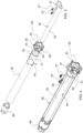
- shows an exploded perspective view of the device according to the invention in a possible embodiment which is particularly suitable for a roll-up cover installation of the "screen" type or with an awning which is movable in a substantially vertical direction,
- Figure 4
- shows a perspective view of the device in
fig. 3 with the casing which is made transparent, - Figure 5
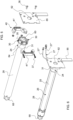
- shows an exploded perspective view of the device according to the invention (without the storage unit) with the means for fixing the head of the device to a lateral bracket of a support structure,
- Figure 6
- shows a perspective view of the device in
fig. 5 with the casing which is made transparent, - Figure 7
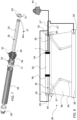
- shows an exploded perspective view of a variant of the device in
fig. 3 , - Figure 8
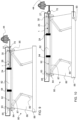
- shows a schematic view of an installation of the roller awning type with an apparatus according to the invention,
- Figure 9
- shows a schematic view of the installation in
fig. 8 with a variant of the apparatus according to the invention, and - Figure 10
- shows a schematic view of the installation in
fig. 8 with a further variant of the apparatus according to the invention. - As can be seen from the figures, the device according to the invention (indicated globally with the reference number 1) is applied/mounted, in the illustrated example, to a roll-up cover installation (indicated globally with the reference number 80).
- The roll-
up cover installation 80 comprises atubular shaft 82, which is actuated (preferably motorized) in rotation about its longitudinal development axis, and also comprises acover element 86 which has a flap attached to thetubular shaft 82 and which, following the rotation of thetubular shaft 82, can be wound around said shaft and unwound from it. - The
device 1 is mounted inside thetubular shaft 82 at a first longitudinal end of saidshaft 82. - Preferably, the roll-up
cover installation 80 can be - from a structural point of view - of a traditional type. Preferably, the roll-upcover installation 80 is of the roller type. Preferably, the roll-upcover installation 80 is motorized but could also be moved manually. - For example, in a possible embodiment illustrated in the figures, the roll-up
cover installation 80 is of the type of cantilever roll-up awning with articulated arms, i.e. it is of the type wherein thecover element 86 is defined by a sheet, which is wound around thetubular shaft 82 and unwound from this, and the installation also includes anexternal support structure 84 to support thetubular shaft 82, arigid crosspiece 88, to which the flap of thecover element 86 opposite to the one attached to thetubular shaft 82 is applied, and two pairs of articulatedarms 89, which connect therigid crosspiece 88 to theexternal support structure 84 and drive it in its translational movements with respect to the latter. - Conveniently, the winding/unwinding of the
cover element 86 can take place along a substantially vertical direction or along a direction more or less inclined with respect to the vertical. - Conveniently, the winding/unwinding of the
cover element 86 around thetubular shaft 82 can take place along lateral tracks for the element itself. - The
tubular shaft 82 is internally hollow and can have any cross section. Preferably, thetubular shaft 82 can have a circular or polygonal section, for example hexagonal, octagonal or similar. - Conveniently, as mentioned, the roll-up
cover installation 80 can also include anexternal support structure 84 for thetubular shaft 82 which is advantageously configured to be mounted to a fixed structure (not shown), for example to a wall surrounding the area of theinstallation 80. - Preferably, this
external support structure 84 can include at least a pair oflateral brackets 85 which suitably support thetubular shaft 82 at its ends and are associated directly, or through other components, to a fixed structure, for example with a wall which surrounds the opening (window, door, glass, etc.) to be covered. Preferably, theexternal support structure 84 can also include arigid band 87, which appropriately adheres to the fixed structure, for example to the wall, and which is fixed directly or by means of a further pair of fixing brackets to the fixed structure. - In a possible embodiment, the
external support structure 84 can include arigid band 87, which appropriately adheres to a fixed structure, for example to a wall of a building, and a pair oflateral brackets 85, preferably wing-shaped, which extend outwards from said rigid band and which suitably support thetubular shaft 82 at the ends. - Conveniently, in a possible embodiment, the
crosspiece 88 can be shaped so that when thecover element 86 is in a wound up condition, the crosspiece itself adheres to theexternal support structure 84 and forms with this a sort of container or" box", which houses inside it thetubular shaft 82, thecover element 86 wound up around it and also any articulatedarms 89, which are in the folded condition. - Conveniently, in a possible embodiment,
lighting elements 90 are mounted on the roll-upcover installation 80 and/or on the external fixed structure surrounding said installation. Advantageously, thelighting elements 90 can be mounted on any component of the roll-upcover installation 80 and in any position of these. For example, thelighting elements 90 can be mounted on theexternal support structure 84 and/or on therigid crosspiece 88 and/or on thetubular shaft 82 and/or even on thecover element 86. - Advantageously, the
lighting elements 90 are light sources and, preferably, are LED strips that define monochromatic and/or RGB light sources. For example, thelighting elements 90 can be made up of at least one LED strip which includes a set of LED diodes, i.e. electronic components which emit light when powered by electricity. Conveniently, the LED diodes are fixed - preferably by welding - on a printed circuit board (PCB), which is preferably flexible, which performs the function of support and electrical connection. Advantageously, the LED diodes of the LED strip can be configured to emit monochromatic light or they can be of the RGB type. - Conveniently, the roll-up
cover installation 80 also includes means configured to cause rotation in both directions of thetubular shaft 82, thus allowing thecover element 86 to be rolled up and unrolled having a flap fixed to said shaft. - Conveniently, a
motorization device 92 can be inserted into thetubular shaft 82 to cause rotation of the shaft itself in both directions around its longitudinal development axis. Preferably, thismotorization device 92 is inserted inside thetubular shaft 82 at a second end of the shaft itself, i.e. at the end which is opposite to the first end of thetubular shaft 82 at whichdevice 1 is inserted. - Conveniently, the
motorization device 92 comprises an electric motor. Preferably, themotorization device 92 comprises a motor configured to provide rotary motion as an output. Preferably, themotorization device 92 comprises a traditional tubular electric driving/pulling motor, preferably of a single-phase asynchronous type, inserted within thetubular shaft 82. Preferably, themotorization device 92 comprises a command and control unit for said motor. - More in detail, conveniently, the
motorization device 92 includes a motor head which is suitably fixed with any known system to thesupport structure 84, preferably fixed to a lateral bracket 85 (for example wing-shaped or defined by a support side plate) of the latter. Themotorization device 92 includes an output pinion to which a pulling adapter (pulley) 94 of thetubular shaft 82 is coupled. Conveniently, a non-pulled adapter can be provided in the vicinity of said motor head of themotorization device 92. - In a possible embodiment, in addition to or instead of the
motorization device 92, means can be provided - which can be manually operated and actuated - which are configured to cause rotation in both directions of thetubular shaft 82. Conveniently, these means configured to cause rotation in both directions of thetubular shaft 82 can be constituted by a traditional hand-operated chain or winch. - Inside the
tubular shaft 82 there is also inserted thedevice 1 according to the invention and, in particular, it is inserted at a first end of thetubular shaft 82. - Preferably, the
device 1 is inserted and housed at one (first) longitudinal end of thetubular shaft 82, while at the other (second/opposite) longitudinal end of the shaft itself themotorization device 92 is inserted and housed. - Advantageously, the
device 1 is substantially independent and autonomous from a constructional and positioning point of view with respect to themotorization device 92 of the roll-upcover installation 80. - The
device 1 is configured to act as a support for thetubular shaft 82 at said first longitudinal end of said shaft. Advantageously, themotorization device 92 can also act as a support for thetubular shaft 82 at the second (opposite) longitudinal end of said shaft. - The
device 1 comprises acasing 28, preferably but not necessarily tubular in shape, which is removably inserted inside thetubular shaft 82. Preferably, thecasing 28 is inserted entirely or mostly inside the first end of thetubular shaft 82. Preferably, thecasing 28 can be made of plastic. - Conveniently, the
device 1 includesmeans 30 for constraining thecasing 28 to saidexternal support structure 84 of saidinstallation 80. - Preferably, the
means 30 for constraining thecasing 28 to saidexternal support structure 84 can be made of plastic. - At least one electrical
energy storage unit 26 is inserted and removably housed inside thecasing 28. Conveniently, said at least one electricalenergy storage unit 26 includes an electric battery. Preferably, said at least one electricenergy storage unit 26 comprises a rechargeable electric battery. Conveniently, said electric battery, which is preferably rechargeable, can be of the traditional type. - Conveniently, said electrical
energy storage unit 26 includes at least oneelectrical connection cable casing 28 and which also protrudes from said means 30 to constrain thecasing 28 to anexternal support structure 84. - Preferably, said at least one electrical
energy storage unit 26 is electrically isolated from thecasing 28 and from themeans 30. - Preferably, said at least one electrical
energy storage unit 26 is housed exclusively and only inside thecasing 28. - Preferably, a battery charger device or other accessories for electrically recharging the electrical
energy storage unit 26 can be housed inside thecasing 28. - Preferably, inside the
casing 28 there is exclusively and only housed said at least one electricalenergy storage unit 26 and, possibly, a battery charger device or other accessories for electrically recharging of the electricalenergy storage unit 26. - Preferably, no control unit is housed inside the
casing 28. Preferably, no processor, microprocessor or microcontroller is housed inside thecasing 28. Preferably, no wireless receiver is housed inside thecasing 28. - Preferably, the
casing 28 is configured (in terms of shape and/or size) to exclusively and only house said at least one electricalenergy storage unit 26 and, possibly, a battery charging device or other accessories for electrically recharging the unit ofelectricity storage 26. - Conveniently, said electrical
energy storage unit 26 comprises abattery body 25 from which at least oneelectrical connection cable - Preferably, the
battery body 25 of said electricalenergy storage unit 26 is entirely housed and inserted inside thecasing 28. - Conveniently, the
battery body 25 of said electricalenergy storage unit 26 can have a cylindrical, box-like shape or in any case any shape such that it can be entirely housed and inserted inside thecasing 28. - Conveniently, the
body 25 of said electricalenergy storage unit 26 can be placed or removably fixed and supported inside thecasing 28. - Conveniently, as mentioned, said electrical
energy storage unit 26 comprises at least oneelectrical connection cable - In a possible embodiment (see
fig. 7 ), said electricalenergy storage unit 26 includes a singleelectrical connection cable 27 which is used and configured both for the transfer of electrical energy from external photovoltaic panels (or other sources of renewable energy) towards thestorage unit 26 and for the transfer of electrical energy from thestorage unit 26 towards themotorization device 92 and/or other electrical users, such as for example towards thelighting elements 90. - In another possible embodiment (see
fig. 3 - 6 ), said electricalenergy storage unit 26 includes two electrical connection cables, and in particular a first electrical connection cable 27' used for transferring electrical energy from external photovoltaic panels (or other renewable energy sources) towards thestorage unit 26, and a secondelectrical connection cable 27" for transferring electrical energy from thestorage unit 26 towards themotorization device 92 and/or other electrical users, such as for example thelighting elements 90, and thus allow their power supply. - The means 30 include a passage (through) opening 60 which is configured to allow the insertion and extraction of the
battery body 25 of said electricalenergy storage unit 26. Conveniently, saidpassage opening 60 is shaped and sized so as to allow a passthrough in both directions by thebattery body 25 of said electricalenergy storage unit 26. In particular, said throughopening 60 can have any shape, even different with respect to the cross section of thebattery body 25, while being such as to allow the passthrough for the insertion/extraction of thebattery body 25 into/from thetubular casing 28. - Conveniently, the
passage opening 60 is also crossed (at least in part) by said at least oneelectric cable electric cable device 1 crossing saidpassage opening 60. Advantageously, therefore, saidbattery body 25 and said at least oneelectric cable same opening 60 of themeans 30 from one side to the other. - Conveniently, the means for constraining the
casing 28 to saidexternal support structure 84 comprise ahead 30 which is associated with the external longitudinal end of thecasing 28 to fix it to theexternal support structure 84. Conveniently, thehead 30 is configured so that, when it is mechanically engaged with thecasing 28, at least a portion of saidhead 30 protrudes from the casing itself. - In particular, the
head 30 makes thecasing 28 integral/fixed (directly or indirectly through means 40) to theexternal support structure 84, thus supporting thetubular shaft 82 at one of its ends. Preferably, thehead 30 is mechanically removably attached to the outer longitudinal end of thecasing 28. - Conveniently, a
closing element 68 can be associated with the internal longitudinal end of thecasing 28, said closingelement 68 which, preferably, can be shaped to support thebattery body 25 inside the casing itself. - Conveniently, said passage opening 60 - which is configured to allow the insertion and extraction of the
battery body 25 of said electrical energy storage unit 26 - is a through opening which is obtained on thehead 30. - Conveniently, the side walls of the
casing 28 are devoid of doors or holes for the passage of said at least oneelectrical connection cable battery body 25 of the electricalenergy storage unit 26. - Conveniently, said
device 1 can include afirst cap 61 to close said passage opening 60 once thebattery body 25 of said electricalenergy storage unit 26 has been inserted inside thecasing 28. Conveniently, saidfirst cap 61 can include at least onehole 65 for the passage of said at least oneelectrical connection cable - Preferably, in a possible embodiment, the
head 30 is fixed directly or indirectly to alateral bracket 85 which, in turn, can advantageously include a further passage opening 62 which is configured to allow the insertion and extraction of thebattery body 25 of said electricalenergy storage unit 26. Conveniently, said further passage opening 62 can have a shape and/or dimensions which are the same as or even different from those of the passage opening 60 of thehead 30. Conveniently, said further passage opening 62 of thelateral bracket 85 faces the passage opening 60 of thehead 30, to thus allow the insertion/extraction of the electricalenergy storage unit 26 into/from thecasing 28 without removing thedevice 1 from theshaft tubular 82 and also without having to remove thelateral bracket 85. - Conveniently, a further cap (not shown) can be provided to close from the outside said further passage opening 62 of the
lateral bracket 85. - Preferably, the
head 30 can also include at least onesection 64 for the passage of at least oneelectrical connection cable section 64 is in communication with thepassage opening 60 and is obtained on a portion of saidhead 30 that protrudes from thecasing 28. Preferably, said at least onepassage section 64 of said at least oneelectric cable 27 or 27' and 27' comprises at least one through notch obtained on thehead portion 30 which protrudes from thecasing 28. Preferably, said at least one through notch develops radially with respect to thepassage opening 60 which is obtained centrally on thehead 30. Advantageously, said at least oneelectric cable 27 or 27' and 27' of the electricalenergy storage unit 60 comes out of thecasing 28 first crossing thepassage opening 60 obtained on thehead 30 and then thesection 64, which is also obtained on thehead 30. Preferably, said at least onesection 64 can be configured so as to clamp or drive said at least oneelectric cable 27, to thus direct its exit direction from thedevice 1. - Conveniently, when the
device 1 is fixed with itshead 30 to thelateral bracket 85, said at least oneelectric cable 27 or 27' and 27' comes out of thehead 30 on the internal side of thelateral bracket 85. - The
device 1 includesmeans 24 for idly supporting thetubular shaft 82, i.e. in such a way as to decouple the rotation of thetubular shaft 82 from thecasing 28. Conveniently, said means 24 are configured to allow thecasing 28 and/or saidhead 30 to support saidtubular shaft 82 in an idle manner, i.e. in such a way as to decouple the rotation of thetubular shaft 82 from thecasing 28 and from thehead 30, thus allowing saidtubular shaft 82 to rotate around its longitudinal development axis while thecasing 28 and thehead 30 remain fixed. - Conveniently, it is understood that the shape and dimensions of the
casing 28 are not linked to those of thetubular shaft 82 although they must evidently be compatible with them. In particular, thecasing 28 has a shape and dimensions suitable to allow its insertion and housing inside thetubular shaft 82. Conveniently, the stability of the positioning of thecasing 28 inside thetubular shaft 82 can be obtained by saidmeans 24. - Conveniently, said means 24 for idly supporting the
tubular shaft 82 can be mounted on saidcasing 28 and/or are mounted on saidhead 30. In particular, said means 24 for idly supporting thetubular shaft 82 can be placed between saidcasing 28 andtubular shaft 82 and/or can be placed between saidhead 30 andtubular shaft 82. - Conveniently, in a possible embodiment (see
fig. 8 - 10 ), themeans 24 can be placed between saidcasing 28 and thetubular shaft 82 and can include at least one adapter which is precisely placed between thecasing 28 and thetubular shaft 82 and which is configured to rotate with saidtubular shaft 82 and to allow thecasing 28 to idly support thetubular shaft 82. Preferably, a pair of support adapters can be provided, interposed between the opposite sides of thecasing 28 and thetubular shaft 82. - Conveniently, in a possible embodiment, a pair of support adapters is provided, spaced apart from each other, and positioned so that a first adapter is positioned or in any case is closer to the innermost end of the
casing 28, while a second adapter is positioned or in any case is closer to the outermost end of thecasing 28. Preferably, in a possible embodiment, said at least one adapter is of the non-pulled type and, in particular, they are mounted idly on thecasing 28, that is, in such a way as to decouple the rotation of thetubular shaft 82 from thecasing 28, thus allowing saidshaft 82 to rotate around its longitudinal development axis while thecasing 28 remains fixed/stationary. - Preferably, in a possible embodiment, both the
head 30 and the adapters of thedevice 1 have a shape similar respectively to that of the corresponding head and the corresponding adapters of themotorization device 92, but unlike those they have the sole function of idle support of thetubular shaft 82 at its end opposite to that of insertion of themotorization device 92. Preferably, thecasing 28 of the control device can be the same (in terms of shape and dimensions) as the corresponding casing of themotorization device 92. - Conveniently, in a possible embodiment (see
fig. 3 - 6 ) which for example is particularly and advantageously suitable for roll-upcover installations 80 of the "screen" type or with awning which is movable in a substantially vertical direction, themeans 24 can be interposed between thehead 30 and thetubular shaft 82 and can include at least one adapter which is interposed between thehead 30 and thetubular shaft 82 and which is configured to rotate with saidtubular shaft 82 and to allow thehead 30 to idly support thetubular shaft 82. In particular, in this case, thehead 30 can support thetubular shaft 82 on its own so that the latter can rotate with respect to said head. Conveniently, in this case, saidtubular casing 28 can be mounted on saidhead 30 so as to be supported exclusively by the head itself. Conveniently, in this case, themeans 24 comprise arotating element 31 which is mounted in an idle manner on thehead 30 and which is intended to be integral in rotation with thetubular shaft 82. In particular, theelement 31 is rotating with respect to the remaining fixed part of the head and supports, possibly by means of an adapter (not shown), thetubular shaft 82 at one of its ends. More in detail, on the fixed (i.e. non-rotating) body of the head 30 arotating element 31 is mounted, preferably of an annular shape, which is made integral in rotation with thetubular shaft 82 and which rotates with respect to the fixed body said head. Conveniently, an adapter for mounting thetubular shaft 82 is then mounted on therotating element 31. In particular, an adapter to support the shaft itself is interposed between therotating element 31 mounted on thehead 30 and thetubular shaft 82. Conveniently, the rotatingelement 31 supports the adapter which thus allows coupling with the various shapes of the cross section of theshaft 82. Conveniently, the rotatingelement 31 is the only element of thedevice 1 which, through the adapter, supports thetubular shaft 82. - Preferably, the
casing 28 can be configured to attach in a removable manner to thehead 30, in particular to aninternal portion 33 of thehead 30. Preferably, saidtubular casing 28 is attached, preferably by means of clip coupling means, to thehead 30. - Preferably, in a possible embodiment, an
internal portion 33 of thehead 30 is inserted into thecasing 28 and these are then fixed to each other by means of a traditional first mechanical locking member 34 (for example a screw or a grub screw). Preferably, in more detail, thecasing 28 and theinternal portion 33 of thehead 30 which fits into the casing are provided with mutual engagement means, defined for example by protruding sections and hollow/holed counter-sections, to thus prevent the movement of the casing with respect to thehead 30, while the engagement defined by said first lockingmember 34 prevents the longitudinal extraction/movement of thecasing 28 with respect to thehead 30. - Conveniently, the
device 1 can include means 40 for fixing thehead 30 to thelateral bracket 85, which can be shaped like a wing (seefig. 2 ) or which can be defined by a side plate (seefig. 5 and 6 ), of theexternal support structure 84. Preferably, said fixing means 40 can include at least twoelements 41' and 41" which laterally clamp an external portion 35 (i.e. a portion that remains outside the casing 28) of thehead 30. - Preferably, in a possible embodiment, the fixing means 40 can comprise at least two elements - 41' and 41" respectively - which laterally clamp an external portion 35 (i.e. the one destined to always remain outside the tubular shaft 82) of the
head 30. Conveniently, at least a first clamping element 41' can be configured so as to be fixed to thelateral bracket 85, preferably by means of second mechanical locking members 36 (for example screws or bolts with corresponding nuts), while the another (second) clampingmember 41" is configured to be fixed to the first clamping element 41', to thus wrap externally - at least in part - theexternal portion 35 of thehead 30. - Conveniently, said
elements 41', 41" clamp theexternal portion 35 of thehead 30 so as to prevent the latter (with the correspondingcasing 28 associated with it) - once clamped - from translating longitudinally (i.e. along an X axis which is substantially corresponding or parallel to the longitudinal axis of thecasing 28 or of the tubular shaft 82) or laterally (i.e. along a direction perpendicular to the X axis), or rotating about the X axis. Therefore, when constraining theclamping elements 41', 41" to thelateral bracket 85, thehead 30 also is thus fixed to saidbracket 85. - Conveniently, said clamping
elements 41' and 41", once arranged in sequence around theexternal portion 35 of thehead 30, are fixed to each other by means of third fixing members 37 (for example screws). - Preferably, the
external portion 35 of thehead 30 defines a profile that is substantially complementary, or at least partly complementary, to that internally delimited by the internal surfaces of the clampingelements 41' and 41". Preferably, theexternal portion 35 of thehead 30 defines a shaped profile/section which engages by interlocking with a profile/section defined on the internal surfaces of the clampingelements 41' and 41". - Conveniently, the
head 30 can include acircumferential flange 42 which separates theexternal portion 35 from the remaining part of the head itself and, in particular, from theinternal portion 33. Advantageously, thecircumferential flange 42 is intended to rest frontally on theclamping elements 41' and 41", once theexternal portion 35 of thestate 30 has been enclosed/embraced between them - Conveniently, the
external portion 35 of thehead 30 is also shaped so that it can be inserted frontally (i.e. along an insertion direction substantially corresponding to or parallel to the X axis), to thus make theflange 42 rest on the first clamping element 41', once this has been fixed to the side bracket 16. - Conveniently, two clamping
elements 41' and 41" are provided which, in combination, laterally wrap theexternal portion 35 of thehead 30, preferably along the entire lateral development of saidportion 35. - Conveniently, the clamping
elements 41' and 41" can also be provided with through holes for the passage of said at least oneelectric cable - Conveniently, in a possible embodiment such as that illustrated in
figures 3 - 6 (which can be particularly and advantageously used forcover installations 80 of the "screen" type or with an awning which is movable in a substantially vertical direction), the removal and replacement of the electricalenergy storage unit 26 can be carried out - if the lateral space available is sufficient - by having thebattery body 25 pass through the passage opening 60 of thehead 30 and the further passage opening 62 of thelateral bracket 85, otherwise - if the lateral space available is not sufficient to carry out the aforementioned operation - it is still possible to act on themeans 40 to thus dissociate thelateral bracket 85 from thehead 30 so as to be able to extract the assembly comprising thehead 30 and thecasing 28 from thetubular shaft 82 of thedevice 1 and thus remove thebattery body 25 from the latter through the passage opening 60 of thehead 30. - Conveniently, the
tubular casing 28 can be made in a single piece or in several pieces that join together, also by mutual mechanical interlocking with shape and/or snap fit. - Advantageously, in the
device 1 according to the invention, inside thecasing 28 exclusively the electricalenergy storage unit 26 is contained (possibly with other devices and accessories for recharging said electrical energy storage unit 26) to supply the electrical energy to the motor of themotorization device 92 and/or to other electrical users, for example to thelighting elements 90. - The present invention also concerns an apparatus for a roll-up
cover installation 80 of the type comprising atubular shaft 82 rotating around its longitudinal development axis and acover element 86 to be wound onto saidtubular shaft 82 and to be unwound from it, and wherein said apparatus includes: - a
device 1, as described above, mounted at a first longitudinal end of thetubular shaft 82, - a
motorization device 92 which is mounted at the second/opposite longitudinal end of thetubular shaft 82, - Conveniently, the apparatus can comprise one or more photovoltaic panels 44 (which preferably can be connected in parallel to each other) which are electrically connected via said at least one
electrical connection cable energy storage unit 26 of thedevice 1 to thus recharge saidunit 26. - Conveniently, the electrical
energy storage unit 26 of thedevice 1 can be electrically connected via said at least onecable 27 or 27' and 27' directly with thephotovoltaic panels 44 and can also be electrically connected via said at least onecable motorization device 92 and/or with other electrical users. - Conveniently, in a possible embodiment represented for example in
fig. 9 , the electricalenergy storage unit 26 of thedevice 1 can be electrically connected via said at least onecable photovoltaic panels 44 and with saidmotorization device 92 and/or with other electrical users via a "T" electrical connector 79 (seefig. 9 ). - Preferably, the electrical
energy storage unit 26 of thedevice 1 comprises a singleelectrical connection cable 27 for transferring electrical energy fromphotovoltaic panels 44 towards thestorage unit 26 and for transferring electrical energy from thestorage unit 26 towards amotorization device 92 of saidtubular shaft 82 of the roll-upcover installation 80 and/or towards other electrical users. - Conveniently, in a possible embodiment represented for example in
fig. 10 , the electricalenergy storage unit 26 of thedevice 1 can be electrically connected via said at least onecable tubular casing 28 of the device 1) and which can be electrically connected with thephotovoltaic panels 44 and can also be electrically connected with saidmotorization device 92 and/or with other electrical users. - Conveniently, the
lighting elements 90 are connected directly or indirectly to theelectrical connection cable energy storage unit 26 of thedevice 1 housed in thetubular shaft 82. - Preferably, said at least one
photovoltaic panel 44 can be mounted on the roll-upcover installation 80, for example it could be mounted on an element of thesupport structure 84, or it can be mounted externally. - Advantageously, by using the
photovoltaic panels 44 to recharge thestorage unit 26 of thedevice 1, themotorization device 92 and/or the other users is/are independent from the external electrical network. In particular, by using thephotovoltaic panels 44 and thedevice 1, the motorization and/or the other electrical users of the roll-upcover installation 80 become completely autonomous and independent from an electrical point of view. - Preferably, the
motorization device 92 can also include within it a further electrical energy storage unit (battery) for said electric motor. - The present invention also concerns a roll-up
cover installation 80 comprising atubular shaft 82 rotating around its longitudinal development axis and acover element 86 to be wound on saidtubular shaft 82 and to be unwound from it. The installation according to the invention is characterized in that it includes an apparatus as described above. In particular, the installation includes adevice 1, as described above, which supports thetubular shaft 82 at a first longitudinal end of said shaft and wherein said device comprises, inside itscasing 28, an electricalenergy storage unit 26 which is electrically rechargeable by means of at least onephotovoltaic panel 44 and which is electrically connected with amotorization device 92 of saidtubular shaft 82 and/or with other electrical users (for example with lighting elements 90) to provide these with the electricity for their operation. - Advantageously, the
device 1 is inserted and housed at a first end of thetubular shaft 82 of theinstallation 80, while at the other end (opposite to the first end) of thetubular shaft 82 themotorization unit 92 is inserted to cause rotation of the shaft itself in both directions. - From what has been said, it is clear that the solution according to the invention is quite advantageous as:
- the
device 1 defines a mechanical connection element between the tubular shaft and the fixed support structure, and at the same time allows the electrical energy storage unit to be housed to supply electrical energy to the motor unit of the tubular shaft of the roll-up cover installation and/or other electrical users, - the connection of the electrical energy storage unit with the photovoltaic panels makes the entire apparatus and installation highly eco-sustainable, as well as substantially autonomous from an electrical point of view,
- the installation and removal of the
device 1 is quite simple and rapid, as it can be carried out even without removing the head and the casing of the device itself from the tubular shaft. - The device according to the present invention has been here described in particular with reference to its application in a roller awning, however it is understood that it can be applied in any roll-up cover installation, whether inclined (cantilevered) or vertical (i.e. wherein the unwinding of the cover element is substantially vertical downwards), such as for example shutters, roller shutters, blackout/filtering curtains, mosquito nets or even sectional doors. In particular, the device can be used both in outdoor installations but also in indoor installations - for example for curtains covering windows, doors, glass windows or other openings in general - where the spaces in length are particularly limited. In more detail, curtains of this type are for example "screen" type roller blinds with the roller blind element which can be defined by a "screen" type fabric sheet (i.e. with a perforated weave that allows to see the outside and not vice versa) and/or blackout and/or filtering and/or mosquito net type.
- The present invention has been illustrated and described in some of its preferred embodiments, but it is understood that executive variations could be made to them in practice without departing from the scope of protection of the present patent for industrial invention.
Claims (15)
- Device (1) for a roll-up cover installation (80), said device (1) being configured to be installed in a roll-up cover installation (80) of the type comprising a tubular shaft (82) which is actuated in rotation around its longitudinal development axis and also comprising a cover element (86) which has a flap fixed to the tubular shaft (82) and which, following the rotation of the tubular shaft (82), can be wound around said shaft and unwound from it, said device (1) being characterized in that it comprises:- a casing (28) which is configured to be removably insertable and housed, entirely or mostly, at a first longitudinal end of said tubular shaft (82), at least one electrical energy storage unit (26) being arranged and housed in a removable manner inside said casing (28) of said device (1),- means (30) to constrain the casing (28) to an external support structure (84),- means (24) for idly supporting the tubular shaft (82),and also characterized in that said at least one electrical energy storage unit (26) includes at least one electrical connection cable (27, 27', 27") which comes out of the casing (28) and also comes out of said means (30) to constrain the casing (28) to an external support structure (84).
- Device according to claim 1, characterized in that inside the casing (28) there is housed exclusively and only said at least one electrical energy storage unit (26) and/or a battery charger device or other accessories for the electrical charging of the electrical energy storage unit (26).
- Device according to one or more of the previous claims, characterized in that said electrical energy storage unit (26) includes a battery body (25) from which said at least one electrical connection cable (27, 27', 27") comes out and in that said means (30) include a passage opening (60) which is configured to allow the insertion and extraction of the battery body (25) of said electrical storage unit (26).
- Device according to one or more of the previous claims, characterized in that said means for constraining the casing (28) to an external support structure (84) comprise a head (30) which is applied to the external longitudinal end of the casing (28) so as to partially protrude from said casing (28) and in that on said head (30) there is a passage opening (60) which is configured to allow the insertion and extraction of the battery body (25) of said electrical energy storage unit (26).
- Device according to one or more of the previous claims, characterized in that said head (30) includes at least one section (64) for the passage of said at least one electrical connection cable (27), said at least one section (64) being defined in a portion of said head (30) which protrudes from the casing (28) and which is in communication with the passage opening (60).
- Device according to one or more of the previous claims, characterized in that said means for constraining the casing (28) to an external support structure (84) comprise:- a head (30) which is associated with the external longitudinal end of the casing (28) to fix it to the external support structure (84),- a passage opening (60) which is configured to allow the insertion and extraction of the battery body (25) of said electrical energy storage unit (26),and wherein said passage opening (60) is shaped and sized so as to allow a passthrough in both directions of the battery body (25) of said electrical energy storage unit (26) and, preferably, also to allow a passthrough of said at least one electrical connection cable (27, 27', 27").
- Device according to one or more of the previous claims, characterized in that said means (24) for idly supporting the tubular shaft (82) are mounted on said casing (28) and/or are mounted on said head (30).
- Device according to one or more of the previous claims, characterized in that it includes a closing element (68) shaped to support said battery body (25) inside said casing (28).
- Device according to one or more of the previous claims, characterized in that it comprises a first cap (61) to close said passage opening (60) once the battery body (25) of said electrical energy storage unit (26) has been inserted inside said casing (28).
- Device according to one or more of the previous claims, characterized in that said casing (28) is configured to attach removably to said head (30).
- Device according to one or more of the previous claims, characterized in that it comprises a single electrical connection cable (27) for transferring electrical energy from external photovoltaic panels towards the electrical energy storage unit (26) and for transferring electrical energy from the electrical energy storage unit (26) towards a motorization device (92) of said tubular shaft (82) of the roll-up cover installation (80) and/or towards other electrical users.
- Device according to one or more of the previous claims, characterized in that said at least one electrical connection cable includes a first electrical connection cable (27') for transferring electrical energy from external photovoltaic panels to the electrical energy storage unit (26), and a second electrical connection cable (27") for transferring electrical energy from the electrical energy storage unit (26) towards a motorization device (92) of said tubular shaft (82) of the installation of roller cover (80) and/or towards other electrical users.
- Apparatus for a roll-up cover installation (80), said apparatus being configured to be installed in a roll-up cover installation (80) of the type comprising a tubular shaft (82) which is rotated around its longitudinal development axis and comprising also a cover element (86) which has a flap fixed to the tubular shaft (82) and which, following the rotation of the tubular shaft (82), can be wound around said shaft and unwound from it, said apparatus being characterized in that it comprises:- a device (1) according to one or more of the previous claims, said device (1) being inserted and housed inside the tubular shaft (82) at a first end of said tubular shaft (82) to thus support said shaft tubular (82) at said first end,- a motorization device (92) to cause rotation in both directions of said tubular shaft (82), said motorization device (92) being mounted at the second/opposite longitudinal end of the tubular shaft (82)and wherein the electrical energy storage unit (26) of the device (1) is configured to be electrically connected via said at least one electrical connection cable (27, 27', 27"), directly or indirectly, with said motorization device (92) and/or with other electrical users, for example with lighting elements (90), to thus provide them with the electrical energy for their operation.
- Apparatus according to the previous claim, characterized in that it comprises at least one photovoltaic panel (44) which is electrically connected via said at least one electrical connection cable (27, 27', 27"), directly or indirectly, with the electrical energy storage unit (26) of the device (1) to thus recharge said electrical energy storage unit (26).
- Roll-up cover installation (80) comprising a tubular shaft (82) rotating around its longitudinal development axis and a cover element (86) to be wound on said tubular shaft (82) and to be unwound from it in a vertical or inclined direction/cantilevered, preferably said cover element (86) being of the type of blackout and/or filtering curtain, roller shutter, mosquito net or sectional door, said installation being characterized in that it comprises an apparatus according to claims 13 or 14.
Applications Claiming Priority (1)
| Application Number | Priority Date | Filing Date | Title |
|---|---|---|---|
| IT202300015408 | 2023-07-21 |
Publications (2)
| Publication Number | Publication Date |
|---|---|
| EP4495372A1 true EP4495372A1 (en) | 2025-01-22 |
| EP4495372B1 EP4495372B1 (en) | 2026-03-04 |
Family
ID=88290662
Family Applications (1)
| Application Number | Title | Priority Date | Filing Date |
|---|---|---|---|
| EP24188127.5A Active EP4495372B1 (en) | 2023-07-21 | 2024-07-11 | Device for a roll-up cover installation |
Country Status (1)
| Country | Link |
|---|---|
| EP (1) | EP4495372B1 (en) |
Citations (7)
| Publication number | Priority date | Publication date | Assignee | Title |
|---|---|---|---|---|
| KR20100118723A (en) | 2009-04-29 | 2010-11-08 | 주식회사 세명차양시스템 | Automatic driving device of slide screen |
| US8371358B1 (en) * | 2008-12-04 | 2013-02-12 | Homerun Holdings Corp | Removable battery system and method |
| AU2014200269A1 (en) | 2010-02-23 | 2014-01-30 | The Watt Stopper, Inc. | High efficiency roller shade |
| US20150179994A1 (en) | 2012-06-13 | 2015-06-25 | Somfy Sas | Element for mounting a battery in a winding tube of a home-automation screen |
| US20150362896A1 (en) | 2014-06-17 | 2015-12-17 | Crestron Electronics, Inc. | Shading Control Network Using a Control Network |
| US20170101820A1 (en) | 2015-10-12 | 2017-04-13 | Crestron Electronics, Inc. | Touch hem bar control |
| WO2019026032A1 (en) | 2017-08-04 | 2019-02-07 | Teleco Automation S.R.L. | A control device for the lighting elements to be mounted on a roller covering installation |
-
2024
- 2024-07-11 EP EP24188127.5A patent/EP4495372B1/en active Active
Patent Citations (7)
| Publication number | Priority date | Publication date | Assignee | Title |
|---|---|---|---|---|
| US8371358B1 (en) * | 2008-12-04 | 2013-02-12 | Homerun Holdings Corp | Removable battery system and method |
| KR20100118723A (en) | 2009-04-29 | 2010-11-08 | 주식회사 세명차양시스템 | Automatic driving device of slide screen |
| AU2014200269A1 (en) | 2010-02-23 | 2014-01-30 | The Watt Stopper, Inc. | High efficiency roller shade |
| US20150179994A1 (en) | 2012-06-13 | 2015-06-25 | Somfy Sas | Element for mounting a battery in a winding tube of a home-automation screen |
| US20150362896A1 (en) | 2014-06-17 | 2015-12-17 | Crestron Electronics, Inc. | Shading Control Network Using a Control Network |
| US20170101820A1 (en) | 2015-10-12 | 2017-04-13 | Crestron Electronics, Inc. | Touch hem bar control |
| WO2019026032A1 (en) | 2017-08-04 | 2019-02-07 | Teleco Automation S.R.L. | A control device for the lighting elements to be mounted on a roller covering installation |
Also Published As
| Publication number | Publication date |
|---|---|
| EP4495372B1 (en) | 2026-03-04 |
Similar Documents
| Publication | Publication Date | Title |
|---|---|---|
| CN110998182B (en) | Controls for lighting elements to be mounted on roller shades | |
| JP4532901B2 (en) | Operator system and opening member including the operator system | |
| US8939190B2 (en) | Motorizable tilt shade system and method | |
| US6338377B1 (en) | Skylight assembly with head rail-mounted actuator | |
| CA1300487C (en) | Drive unit for a vertical blind or the like and vertical blind utilizing same | |
| NL1007549C2 (en) | Sun blinds with lighting. | |
| EP3670780B1 (en) | A device for controlling a roll-up cover installation | |
| CN107923220A (en) | Closing or sunshade home automation installation and the accumulator charging method of this equipment | |
| KR101211959B1 (en) | Electromotive blind apparatus | |
| EP4495372B1 (en) | Device for a roll-up cover installation | |
| CN105156005B (en) | shading device | |
| CA2431343A1 (en) | Tubular motor | |
| EP4524343A1 (en) | Device for a roller cover installation | |
| EP4095344B1 (en) | Control device for lighting elements to be mounted on a roll-up cover installation | |
| CN115715346A (en) | Electromechanical actuator for a blind device and blind device comprising such an electromechanical actuator | |
| EP1105614B1 (en) | A screening arrangement for a window and a universal mounting and parallel guiding arrangement for a window screening device | |
| CN215015987U (en) | Intelligent curtain device of free installation | |
| EP4202176B1 (en) | An improved driving device | |
| EP4180615B1 (en) | Motorization device | |
| US11913282B2 (en) | Roller blind assembly | |
| HK1106567A (en) | Operator system and an aperture member comprising such a system |
Legal Events
| Date | Code | Title | Description |
|---|---|---|---|
| PUAI | Public reference made under article 153(3) epc to a published international application that has entered the european phase |
Free format text: ORIGINAL CODE: 0009012 |
|
| STAA | Information on the status of an ep patent application or granted ep patent |
Free format text: STATUS: THE APPLICATION HAS BEEN PUBLISHED |
|
| AK | Designated contracting states |
Kind code of ref document: A1 Designated state(s): AL AT BE BG CH CY CZ DE DK EE ES FI FR GB GR HR HU IE IS IT LI LT LU LV MC ME MK MT NL NO PL PT RO RS SE SI SK SM TR |
|
| STAA | Information on the status of an ep patent application or granted ep patent |
Free format text: STATUS: REQUEST FOR EXAMINATION WAS MADE |
|
| 17P | Request for examination filed |
Effective date: 20250715 |
|
| GRAP | Despatch of communication of intention to grant a patent |
Free format text: ORIGINAL CODE: EPIDOSNIGR1 |
|
| STAA | Information on the status of an ep patent application or granted ep patent |
Free format text: STATUS: GRANT OF PATENT IS INTENDED |
|
| RIC1 | Information provided on ipc code assigned before grant |
Ipc: E06B 9/174 20060101AFI20251016BHEP Ipc: E06B 9/72 20060101ALI20251016BHEP Ipc: E04F 10/06 20060101ALN20251016BHEP Ipc: E06B 9/24 20060101ALN20251016BHEP |
|
| RIC1 | Information provided on ipc code assigned before grant |
Ipc: E06B 9/174 20060101AFI20251021BHEP Ipc: E06B 9/72 20060101ALI20251021BHEP Ipc: E04F 10/06 20060101ALN20251021BHEP Ipc: E06B 9/24 20060101ALN20251021BHEP |
|
| INTG | Intention to grant announced |
Effective date: 20251106 |
|
| GRAS | Grant fee paid |
Free format text: ORIGINAL CODE: EPIDOSNIGR3 |
|
| GRAA | (expected) grant |
Free format text: ORIGINAL CODE: 0009210 |
|
| STAA | Information on the status of an ep patent application or granted ep patent |
Free format text: STATUS: THE PATENT HAS BEEN GRANTED |
|
| AK | Designated contracting states |
Kind code of ref document: B1 Designated state(s): AL AT BE BG CH CY CZ DE DK EE ES FI FR GB GR HR HU IE IS IT LI LT LU LV MC ME MK MT NL NO PL PT RO RS SE SI SK SM TR |
|
| REG | Reference to a national code |
Ref country code: CH Ref legal event code: F10 Free format text: ST27 STATUS EVENT CODE: U-0-0-F10-F00 (AS PROVIDED BY THE NATIONAL OFFICE) Effective date: 20260304 Ref country code: GB Ref legal event code: FG4D |
|
| REG | Reference to a national code |
Ref country code: IE Ref legal event code: FG4D |
|
| REG | Reference to a national code |
Ref country code: DE Ref legal event code: R096 Ref document number: 602024002961 Country of ref document: DE |
|
| PG25 | Lapsed in a contracting state [announced via postgrant information from national office to epo] |
Ref country code: RS Free format text: LAPSE BECAUSE OF FAILURE TO SUBMIT A TRANSLATION OF THE DESCRIPTION OR TO PAY THE FEE WITHIN THE PRESCRIBED TIME-LIMIT Effective date: 20260604 |
|
| PG25 | Lapsed in a contracting state [announced via postgrant information from national office to epo] |
Ref country code: ES Free format text: LAPSE BECAUSE OF FAILURE TO SUBMIT A TRANSLATION OF THE DESCRIPTION OR TO PAY THE FEE WITHIN THE PRESCRIBED TIME-LIMIT Effective date: 20260304 |
|
| REG | Reference to a national code |
Ref country code: NL Ref legal event code: MP Effective date: 20260304 |
|
| PG25 | Lapsed in a contracting state [announced via postgrant information from national office to epo] |
Ref country code: PL Free format text: LAPSE BECAUSE OF FAILURE TO SUBMIT A TRANSLATION OF THE DESCRIPTION OR TO PAY THE FEE WITHIN THE PRESCRIBED TIME-LIMIT Effective date: 20260304 |
|
| PG25 | Lapsed in a contracting state [announced via postgrant information from national office to epo] |
Ref country code: GR Free format text: LAPSE BECAUSE OF FAILURE TO SUBMIT A TRANSLATION OF THE DESCRIPTION OR TO PAY THE FEE WITHIN THE PRESCRIBED TIME-LIMIT Effective date: 20260605 |
|
| REG | Reference to a national code |
Ref country code: LT Ref legal event code: MG9D |
|
| PG25 | Lapsed in a contracting state [announced via postgrant information from national office to epo] |
Ref country code: LT Free format text: LAPSE BECAUSE OF FAILURE TO SUBMIT A TRANSLATION OF THE DESCRIPTION OR TO PAY THE FEE WITHIN THE PRESCRIBED TIME-LIMIT Effective date: 20260304 |
|
| PG25 | Lapsed in a contracting state [announced via postgrant information from national office to epo] |
Ref country code: NO Free format text: LAPSE BECAUSE OF FAILURE TO SUBMIT A TRANSLATION OF THE DESCRIPTION OR TO PAY THE FEE WITHIN THE PRESCRIBED TIME-LIMIT Effective date: 20260604 |
|
| PG25 | Lapsed in a contracting state [announced via postgrant information from national office to epo] |
Ref country code: SE Free format text: LAPSE BECAUSE OF FAILURE TO SUBMIT A TRANSLATION OF THE DESCRIPTION OR TO PAY THE FEE WITHIN THE PRESCRIBED TIME-LIMIT Effective date: 20260304 Ref country code: FI Free format text: LAPSE BECAUSE OF FAILURE TO SUBMIT A TRANSLATION OF THE DESCRIPTION OR TO PAY THE FEE WITHIN THE PRESCRIBED TIME-LIMIT Effective date: 20260304 |
|
| PG25 | Lapsed in a contracting state [announced via postgrant information from national office to epo] |
Ref country code: HR Free format text: LAPSE BECAUSE OF FAILURE TO SUBMIT A TRANSLATION OF THE DESCRIPTION OR TO PAY THE FEE WITHIN THE PRESCRIBED TIME-LIMIT Effective date: 20260304 |
|
| PG25 | Lapsed in a contracting state [announced via postgrant information from national office to epo] |
Ref country code: LV Free format text: LAPSE BECAUSE OF FAILURE TO SUBMIT A TRANSLATION OF THE DESCRIPTION OR TO PAY THE FEE WITHIN THE PRESCRIBED TIME-LIMIT Effective date: 20260304 |
|
| PG25 | Lapsed in a contracting state [announced via postgrant information from national office to epo] |
Ref country code: BG Free format text: LAPSE BECAUSE OF FAILURE TO SUBMIT A TRANSLATION OF THE DESCRIPTION OR TO PAY THE FEE WITHIN THE PRESCRIBED TIME-LIMIT Effective date: 20260304 |