EP4495334A1 - Control device, control method, and work machine - Google Patents
Control device, control method, and work machine Download PDFInfo
- Publication number
- EP4495334A1 EP4495334A1 EP23859833.8A EP23859833A EP4495334A1 EP 4495334 A1 EP4495334 A1 EP 4495334A1 EP 23859833 A EP23859833 A EP 23859833A EP 4495334 A1 EP4495334 A1 EP 4495334A1
- Authority
- EP
- European Patent Office
- Prior art keywords
- work equipment
- lock
- signal line
- state
- push button
- Prior art date
- Legal status (The legal status is an assumption and is not a legal conclusion. Google has not performed a legal analysis and makes no representation as to the accuracy of the status listed.)
- Pending
Links
Images






Classifications
-
- E—FIXED CONSTRUCTIONS
- E02—HYDRAULIC ENGINEERING; FOUNDATIONS; SOIL SHIFTING
- E02F—DREDGING; SOIL-SHIFTING
- E02F9/00—Component parts of dredgers or soil-shifting machines, not restricted to one of the kinds covered by groups E02F3/00 - E02F7/00
- E02F9/20—Drives; Control devices
- E02F9/2004—Control mechanisms, e.g. control levers
- E02F9/2012—Setting the functions of the control levers, e.g. changing assigned functions among operations levers, setting functions dependent on the operator or seat orientation
-
- E—FIXED CONSTRUCTIONS
- E02—HYDRAULIC ENGINEERING; FOUNDATIONS; SOIL SHIFTING
- E02F—DREDGING; SOIL-SHIFTING
- E02F3/00—Dredgers; Soil-shifting machines
- E02F3/04—Dredgers; Soil-shifting machines mechanically-driven
- E02F3/28—Dredgers; Soil-shifting machines mechanically-driven with digging tools mounted on a dipper- or bucket-arm, i.e. there is either one arm or a pair of arms, e.g. dippers, buckets
- E02F3/36—Component parts
- E02F3/42—Drives for dippers, buckets, dipper-arms or bucket-arms
- E02F3/43—Control of dipper or bucket position; Control of sequence of drive operations
- E02F3/431—Control of dipper or bucket position; Control of sequence of drive operations for bucket-arms, front-end loaders, dumpers or the like
- E02F3/434—Control of dipper or bucket position; Control of sequence of drive operations for bucket-arms, front-end loaders, dumpers or the like providing automatic sequences of movements, e.g. automatic dumping or loading, automatic return-to-dig
-
- E—FIXED CONSTRUCTIONS
- E02—HYDRAULIC ENGINEERING; FOUNDATIONS; SOIL SHIFTING
- E02F—DREDGING; SOIL-SHIFTING
- E02F9/00—Component parts of dredgers or soil-shifting machines, not restricted to one of the kinds covered by groups E02F3/00 - E02F7/00
- E02F9/20—Drives; Control devices
- E02F9/22—Hydraulic or pneumatic drives
- E02F9/226—Safety arrangements, e.g. hydraulic driven fans, preventing cavitation, leakage, overheating
Definitions
- Patent Document 1 discloses a safety device for a work machine in which a position of a gate lock lever that blocks or communicates with a hydraulic flow path of a hydraulic pressure to a hydraulic operating device of work equipment is detected by a plurality of systems such as a combination of two switches and a combination of one switch and one potentiometer.
- a position of a gate lock lever that blocks or communicates with a hydraulic flow path of a hydraulic pressure to a hydraulic operating device of work equipment is detected by a plurality of systems such as a combination of two switches and a combination of one switch and one potentiometer.
- the hydraulic flow path is blocked when input signals from the two switches are different from each other.
- the hydraulic flow path is blocked when the switch is failed, or is blocked or communicated according to a signal from the potentiometer.
- Patent Document 1 Japanese Unexamined Patent Application, First Publication No. 2006-274788
- a work machine including work equipment in a case where the operation of the work equipment is stopped in the occurrence of a failure, it may be difficult to move the work machine depending on a posture (position, angle, and the like) of the work equipment at the time of the stop.
- a posture position, angle, and the like
- the degree of maintenance of the minimum function such as a traveling function in a case where a failure occurs is referred to as emergency operability.
- emergency operability for example, even in a case where a failure occurs, the posture of the work equipment can be returned to a posture suitable for traveling, and in a case where there is no problem in traveling of the work machine, the emergency operability is good.
- the safety can be improved by multiplexing the system by using a plurality of systems for detecting the position of the gate lock lever.
- the position of the gate lock lever is detected by the combination of two switches, the work equipment is stopped in a case where a failure occurs, so that there is a problem that emergency operability is deteriorated.
- the configuration using the potentiometer there is a problem that it is difficult to simplify the structure.
- the present disclosure has been made in view of the above circumstances, and an object of the present disclosure is to provide a control device, a control method, and a work machine capable of achieving both safety and emergency operability in a configuration for locking an operation of the work equipment.
- a control device of a work machine including work equipment, the control device including: a signal input unit configured to input a signal from a first signal line connected to a normally open first switch configured to detect press and release of a momentary operation push button for setting and releasing lock of an operation of the work equipment, and input a signal from a second signal line connected to a normally closed second switch linked to the first switch (hereinafter, a state where the push button is pressed is referred to as ON, and a state where the push button is released is referred to as OFF); and a work equipment lock control unit configured to altemately switch between setting and releasing the lock of the operation of the work equipment in a case where information indicating that the push button is OFF ⁇ ON ⁇ OFF is obtained from both of the first signal line and the second signal line, and release the lock of the operation of the work equipment only when a predetermined operation is performed on a predetermined operation device of the work equipment when the lock of the operation of the work equipment is set
- a control method of a work machine including work equipment including: a step of inputting a signal from a first signal line connected to a normally open first switch configured to detect press and release of a momentary operation push button for setting and releasing lock of an operation of the work equipment, and inputting a signal from a second signal line connected to a normally closed second switch linked to the first switch (hereinafter, a state where the push button is pressed is referred to as ON, and a state where the push button is released is referred to as OFF); a step of alternately switching between setting and releasing the lock of the operation of the work equipment in a case where information indicating that the push button is OFF ⁇ ON ⁇ OFF is obtained from both of the first signal line and the second signal line; and a step of releasing the lock of the operation of the work equipment only when a predetermined operation is performed on a predetermined operation device of the work equipment when the lock of the operation of the work equipment is set in a
- a work machine including: work equipment; and a control device including a signal input unit configured to input a signal from a first signal line connected to a normally open first switch configured to detect press and release of a momentary operation push button for setting and releasing lock of an operation of the work equipment, and input a signal from a second signal line connected to a normally closed second switch linked to the first switch (hereinafter, a state where the push button is pressed is referred to as ON, and a state where the push button is released is referred to as OFF), and a work equipment lock control unit configured to alternately switch between setting and releasing the lock of the operation of the work equipment in a case where information indicating that the push button is OFF ⁇ ON ⁇ OFF is obtained from both of the first signal line and the second signal line, and release the lock of the operation of the work equipment only when a predetermined operation is performed on a predetermined operation device of the work equipment when the lock of the operation of the work equipment is set in a case
- control device the control method, and the work machine of the present disclosure, it is possible to achieve both safety and emergency operability in a configuration for locking the operation of the work equipment.
- FIG. 1 is a side view showing a work machine according to an embodiment of the present disclosure.
- FIG. 2 is a perspective view schematically showing the periphery of a driver's seat according to the embodiment of the present disclosure.
- FIG. 3 is a perspective view schematically showing a portion A1 shown in FIG. 2 .
- FIGS. 4 and 5 are block diagrams showing a configuration example of a control system of the work machine according to the embodiment of the present disclosure.
- FIGS. 6 and 7 are schematic diagrams for describing an operation example of the work equipment controller according to the embodiment of the present disclosure.
- FIG. 8 is a state transition diagram showing an operation example of a work equipment controller according to the embodiment of the present disclosure.
- FIGS. 1 is a side view showing a work machine according to an embodiment of the present disclosure.
- FIG. 2 is a perspective view schematically showing the periphery of a driver's seat according to the embodiment of the present disclosure.
- FIG. 3 is a perspective view schematically showing a portion A
- FIG. 9 to 20 are schematic diagrams for describing operation examples of the work equipment controller according to the embodiment of the present disclosure.
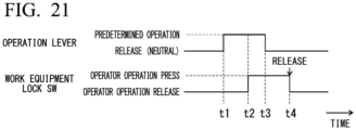
- FIG. 21 is a timing chart for describing an operation example of the work equipment controller according to the embodiment of the present disclosure.
- the same reference numerals are used for the same or corresponding components, and the description thereof will be omitted as appropriate.
- a local coordinate system is set in a work machine 1, and a positional relationship of each unit will be described with reference to the local coordinate system.
- a first axis extending in a right-left direction (vehicle width direction) of the work machine 1 will be defined as an X-axis
- a second axis extending in a front-rear direction of the work machine 1 will be defined as a Y-axis
- a third axis extending in an up-down direction of the work machine 1 will be defined as a Z-axis.
- the X-axis and the Y-axis are orthogonal to each other.
- the Y-axis and the Z-axis are orthogonal to each other.
- the Z-axis and the X-axis are orthogonal to each other.
- a +X-direction is the right direction, and a -X-direction is the left direction.
- a +Y-direction is the front direction, and a -Y-direction is the rear direction.
- a +Z-direction is the up direction, and a -Z-direction is the down direction.
- FIG. 1 shows a work machine 1 according to the present embodiment.
- the work machine 1 according to the present embodiment is a wheel loader.
- the work machine 1 will be referred to as a wheel loader 1 as appropriate.
- the wheel loader 1 has a vehicle body 2, a cab 3, a traveling device 4, and work equipment 10.
- the wheel loader 1 travels on a work place by using the traveling device 4.
- the wheel loader 1 carries out work by using the work equipment 10.
- the wheel loader 1 can use the work equipment 10 to carry out the work, such as excavation work, loading work, transport work, and snow removal work.
- the cab 3 is supported by the vehicle body 2. Inside the cab 3, a driver's seat 31 on which an operator sits, an operation device 32 to be described later, a display and input unit 35, and an output unit 36 are disposed.
- the operation device 32 includes a boom operation lever 33, a bucket operation lever 34, and a work equipment lock switch 37.
- the traveling device 4 includes, for example, a transmission, a drive shaft, a brake, and a rotatable wheel 5.
- the traveling device 4 includes, for example, a transmission that has a forward speed stage of 1 to 8 and a backward speed stage of 1 to 4. The smaller the number of the speed stage, the lower the speed.
- the wheels 5 support the vehicle body 2.
- the wheel loader 1 can travel on a road surface (or ground) RS by the traveling device 4. It should be noted that FIG. 1 shows only a front wheel 5F and a rear wheel 5R on a left side.
- the front wheel 5F may be driven by, for example, a hydraulic motor (not shown).
- the work equipment 10 is supported by vehicle body 2.
- the work equipment 10 is configured by a bucket 12 as an example of a work tool, and a movable support section 17 that changes a position and a posture of the bucket 12.
- the movable support section 17 includes a boom 11, a boom cylinder 13, a bucket cylinder 14, a bell crank 15, and a link 16.
- the boom 11 is rotatably supported with respect to the vehicle body 2, and moves in the up-down direction according to expansion and contraction of the boom cylinder 13.
- the boom cylinder 13 is an actuator that generates power for moving the boom 11, and has one end portion connected to the vehicle body 2 and the other end portion connected to the boom 11.
- the boom cylinder 13 contracts and extends.
- the boom cylinder 13 is, for example, a hydraulic cylinder.
- the bucket 12 is a container for an object such as earth, has bucket teeth 12T, and is a work tool for performing excavation of the object to be excavated such as earth or loading thereof.
- the bucket 12 is rotatably connected to the boom 11, and is rotatably connected to one end portion of the link 16.
- the other end portion of the link 16 is rotatably connected to one end portion of the bell crank 15.
- the bell crank 15 has a central portion connected to the boom 11 to be rotationally movable, and the other end portion rotatably connected to one end portion of the bucket cylinder 14.
- the other end portion of the bucket cylinder 14 is rotatably connected to the vehicle body 2.
- the bucket 12 is operated by power generated by the bucket cylinder 14.
- the bucket cylinder 14 is an actuator that generates power for moving the bucket 12.
- the bucket cylinder 14 is contracted and extended. As a result, the bucket 12 swings.
- the bucket cylinder 14 is, for example, a hydraulic cylinder.
- the bucket teeth 12T has a shape of chevron teeth, flat teeth, or the like, and is attached to an end portion of the bucket 12 to be replaceable.
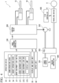
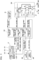
- FIGS. 4 and 5 are block diagrams showing a configuration example of a control system of the wheel loader 1 according to the present embodiment.
- the wheel loader 1 includes a power source 201, a power take off (PTO) 202, a hydraulic pump 203, a control valve 200, an operation device 32, a display and input unit 35, an output unit 36, a work equipment controller 100, an engine controller 300, and a transmission (T/M) controller 400.
- PTO power take off
- T/M transmission
- the power source 201 generates a driving force for operating the work machine.
- An intemal combustion engine and an electric motor are exemplary examples of the power source.
- the power source 201 is an internal combustion engine (engine).
- the PTO 202 transmits at least a part of the driving force of the power source 201 to the hydraulic pump 203.
- the PTO 202 distributes the driving force of the power source 201 to the traveling device 4 and the hydraulic pump 203.
- the hydraulic pump 203 is driven by the power source 201, and discharges a hydraulic oil. At least a part of the hydraulic oil discharged from the hydraulic pump 203 is supplied to each of the boom cylinder 13 and the bucket cylinder 14 via the control valve 200.
- the control valve 200 receives a predetermined control signal (work equipment EPC signal) from the work equipment controller 100 and controls the flow rate, the pressure, and the direction of the hydraulic oil supplied to each of the boom cylinder 13 and the bucket cylinder 14 from the hydraulic pump 203.
- the work equipment 10 is operated by the hydraulic oil from the hydraulic pump 203.
- the boom operation lever 33 is an operation lever for operating the posture of the boom 11. In a case where the boom operation lever 33 is tilted in the rear direction, the boom 11 moves in the upward direction. In a case where the boom operation lever 33 is tilted in the front direction, the boom 11 moves in the downward direction. The movement speed is changed according to a tilt amount of the boom operation lever 33. The larger the tilt amount, the higher the speed.
- the bucket operation lever 34 is an operation lever for operating the posture of the bucket 12. In a case where the bucket operation lever 34 is tilted in the rear direction, the bucket 12 is moved in a tilt direction (a direction in which the bucket teeth 12T faces upward as shown in FIG. 1 ).
- the bucket 12 In a case where the bucket operation lever 34 is tilted in the front direction, the bucket 12 is moved in a dump direction (direction in which the bucket teeth 12T shown in FIG. 1 faces downward). The movement speed is changed according to the tilt amount of the bucket operation lever 34. The larger the tilt amount, the higher the speed.
- the boom operation lever 33 and the bucket operation lever 34 include one or a plurality of stroke sensors therein, detect the tilt amount of the operation lever, and output a detection signal (work equipment lever signal in FIG. 5 ) indicating the detection result as an analog voltage value.
- the work equipment lock switch 37 is a push button switch (push button according to the present disclosure) for setting and releasing the lock of the operation of the work equipment 10.
- the work equipment lock switch 37 is a momentary operation push button switch. That is, the work equipment lock switch 37 is turned on only while the button is being pressed by the hand or the like, and is returned to the off state in a case where the hand or the like is separated from the button.
- the work equipment lock switch 37 includes a work equipment lock switch (SW)1 (371) and a work equipment lock switch (SW)2 (372).
- the work equipment lock SW1 (371) is a normally open switch (first switch according to the present disclosure) that detects the press and release of the work equipment lock switch 37.
- the work equipment lock SW1 (371) is turned on while the button is being pressed, and is turned off in a case where the button is released.
- the work equipment lock SW2 (372) is a normally closed switch (second switch according to the present disclosure) that detects the press and release of the work equipment lock switch 37 linked to the work equipment lock SW1 (371).
- the work equipment lock SW2 (372) is turned off while the button is being pressed, and is turned on in a case where the button is released.
- the work equipment lock switch 37 includes a display lamp 373 consisting of a light emitting diode (LED).
- the display lamp 373 is controlled by the work equipment controller 100 to be turned on in a state where the work equipment 10 is not operated, that is, in a state where the operation of the work equipment 10 is locked (in the present embodiment, this state is also referred to as a state where the work equipment is set to be locked), and to be turned off in a state where the work equipment 10 can be operated, that is, in a state where the lock of the operation of the work equipment 10 is released.
- SW a state where the work equipment lock switch 37 (push button) is pressed
- OFF a state where the work equipment lock switch 37 (push button) is released
- the work equipment lock switch 37 may be simply referred to as "SW”.
- SW normality means a state in which the work equipment lock SW1 (371) and the work equipment lock SW2 (372) are normally operated.
- SW abnormality means a state in which the ground fault, power supply fault, or disconnection failure is generated in any of the work equipment lock SW1 (371) or the work equipment lock SW2 (372).
- one terminal of the work equipment lock SW1 (371) is connected to the DC power supply (24 V in the present embodiment), and the other terminal is connected to the work equipment controller 100.
- a signal line that connects the other terminal of the work equipment lock SW1 (371) to an input circuit (not shown) in the work equipment controller 100 is a first signal line, and a signal name on the first signal line is the work equipment lock SW1.
- One terminal of the work equipment lock SW2 (372) is connected to the DC power supply, and the other terminal is connected to the work equipment controller 100.
- a signal line that connects the other terminal of the work equipment lock SW2 (372) to an input circuit (not shown) in the work equipment controller 100 is a second signal line, and a signal name on the second signal line is the work equipment lock SW2.
- the first signal line and the second signal line are pulled down through a predetermined resistor in the work equipment controller 100.
- the display and input unit 35 shown in FIG. 4 is configured with a combination of an input device and a display device, an input display device such as a touch panel, and the like.
- the operator inputs, for example, a set value or the like in the control of the work equipment 10 or displays information indicating the content in a case where a failure or the like occurs, using the display and input unit 35.
- the display and input unit 35 displays predetermined information in response to the monitor display indicator signal received from the work equipment controller 100.
- the output unit 36 includes a display device, a synthetic voice, an output device of an alarm sound or a notification sound, a display lamp such as a warning lamp, and the like, and outputs predetermined information.
- the engine controller 300 shown in FIG. 4 controls the power source 201 according to an operation of an accelerator pedal (not shown) provided in the operation device 32.
- the engine controller 300 has an auto-idle stop function of automatically stopping the engine in a case where the idling state is continued for an idling time set by the operator.
- the engine controller 300 transmits an idle step status signal indicating whether or not the power source 201 is stopped by the auto-idle stop function, to the work equipment controller 100.
- the T/M controller 400 shown in FIG. 4 controls a transmission (not shown) provided in the traveling device 4 according to an operation of a shift lever (not shown) provided in the operation device 32.
- the T/M controller 400 transmits a signal (travel damper SW signal) indicating whether or not a traveling damper function is operating, a signal indicating the vehicle speed, a signal requesting the lock of the work equipment 10, and the like to the work equipment controller 100.
- the traveling damper function is a function of reducing the vibration caused by traveling by connecting the boom cylinder 13 to an accumulator (not shown) in the control valve 200 during traveling to control the pressure accumulation of the accumulator.
- the signal for requesting the lock of the work equipment 10 is generated, for example, in a case where it is necessary to give priority to the traveling side over the work of the work equipment 10 in a case where the work equipment 10 is traveling on a steep slope or the like.
- the work equipment controller 100 is formed using, for example, a field programmable gate array (FPGA) or a microcomputer that includes a processor, a main storage device, an auxiliary storage device, an input/output device, and the like.
- the work equipment controller 100 includes, as a functional configuration constituted by hardware or a combination of hardware and software such as a program, a work equipment control unit 101, a signal input unit 102, a work equipment lock control unit 103, and an alarm activation unit 104.
- the work equipment controller 100 is an example of a control device according to the present disclosure.
- the work equipment control unit 101 drives and controls the boom cylinder 13, the bucket cylinder 14, and the like by outputting a work equipment electric pressure control (EPC) signal in response to the work equipment lever signal and the like output from the operation device 32 and controlling the control valve 200.
- FIG. 5 shows a configuration of a part of the control valve 200.
- the work equipment EPC signal indicates one of the plurality of work equipment EPC signals.
- the pressure control valve 211 controls hydraulic oil supplied to the boom cylinder 13, the bucket cylinder 14, and the like by variably controlling an operation of a solenoid 211s according to the work equipment EPC signal.
- the work equipment control unit 101 determines whether or not there is an abnormality in the work equipment lever according to the work equipment lever signal or the like output by the operation device 32. In a case where it is determined that there is the abnormality, the work equipment control unit 101 stops the drive of the work equipment 10 or implements the function restriction of limiting the drive speed of the work equipment 10.
- the signal input unit 102 repeatedly inputs the work equipment lock SW1 signal and the work equipment lock SW2 signal, for example, at a predetermined cycle. That is, the signal input unit 102 inputs the work equipment lock SW1 signal from a signal line (referred to as a first signal line) connected to the normally open work equipment lock SW1 (first switch) 371 that detects the press and release of the work equipment lock switch 37, which is a momentary operation push button for setting and releasing the lock of the operation of the work equipment 10, and inputs the work equipment lock SW2 signal from a signal line (referred to as a second signal line) connected to the work equipment lock SW2 (second switch) 372 of the normally closed type linked to the work equipment lock SW1.
- a signal line referred to as a first signal line
- the normally open work equipment lock SW1 (first switch) 371 that detects the press and release of the work equipment lock switch 37, which is a momentary operation push button for setting and releasing the lock of the operation of the work equipment 10
- the work equipment controller 100 has a step of inputting a signal from the first signal line connected to the normally open first switch that detects the press and release of the momentary operation push button for setting and releasing the lock of the operation of the work equipment 10 and is connected to the first switch, and inputting the signal from the second signal line connected to the normally closed second switch linked to the first switch.
- the work equipment lock control unit 103 outputs a work equipment lock solenoid (SOL) signal in response to the work equipment lock SW1 signal, the work equipment lock SW2 signal, and the like input from the work equipment lock switch 37, and turns on or off the direction control valve 212 to block or supply the hydraulic oil supplied to the boom cylinder 13, the bucket cylinder 14, and the like.
- the work equipment lock SOL signal is turned on to apply a direct current of 24 V to a solenoid 212s of the direction control valve 212 to block the hydraulic oil
- the work equipment lock SOL signal is turned off to be the open state to supply the hydraulic oil.
- the state in which the hydraulic oil is blocked is a state in which the work equipment 10 is locked (state in which the lock is set)
- the state in which the hydraulic oil is supplied is a state in which the lock of the work equipment 10 is released.
- the work equipment lock control unit 103 In a case where information indicating that the work equipment lock switch 37 (push button) is OFF ⁇ ON ⁇ OFF is obtained from both of the first signal line and the second signal line, the work equipment lock control unit 103 altemately switches between setting and releasing the lock of the operation of the work equipment 10, and in a case where information indicating that the work equipment lock switch 37 (push button) is OFF ⁇ ON ⁇ OFF is obtained from only one of the first signal line and the second signal line, the work equipment lock control unit 103 releases the lock of the operation of the work equipment 10 only when a predetermined operation is performed on a predetermined operation device 32 of the work equipment 10 when the lock of the operation of the work equipment 10 is set.
- the predetermined operation can include, for example, an operation by a combination of predetermined operations for a plurality of operation levers included in the operation device 32.
- the predetermined operation can include, for example, an operation of simultaneously performing an operation of driving the bucket 12 at a predetermined speed or more in the dump direction with respect to the bucket operation lever 34 for driving the bucket 12 in the dump direction and the tilt direction and an operation of driving the boom 11 at the predetermined speed or more in the lowering direction with respect to the boom operation lever 33 for driving the boom 11 in the up-down direction.
- the work equipment controller 100 has a step of altemately switching the setting and the release of the lock of the operation of the work equipment 10, and in a case where information indicating that the push button is OFF ⁇ ON - OFF is obtained from only one of the first signal line and the second signal line, the work equipment controller 100 has a step of releasing the lock of the operation of the work equipment 10 only in a case where a predetermined operation is performed on a predetermined operation device of the work equipment 10 when the lock of the operation of the work equipment 10 is set.
- the work equipment lock control unit 103 sets the lock of the work equipment 10 when the work equipment 10 is controlled to be in a stop state.
- the lock of the work equipment 10 is automatically locked (set to the lock) from the release without the operation of the operator, the lock is set when the work equipment 10 is controlled to be in the stop state. According to this configuration, it is possible to prevent the work equipment 10 from being suddenly stopped when the automatic locking is performed, and for example, it is possible to prevent a large forward fall or an impact from being generated.
- the alarm activation unit 104 reports that fact to the display and input unit 35, the output unit 36, and the like.
- FIG. 6 shows a correspondence relationship between a combination of a state of "Hi” (high level) or “Lo” (low level) of the work equipment lock SW1 signal and a state of "Hi” or “Lo” of the work equipment lock SW2 signal, and results of the operation determination and the abnormality determination.
- one of the work equipment lock SW1 signal and the work equipment lock SW2 signal is "Hi"
- the other is "Lo”.
- FIG. 7 shows the classification of the operation states based on the work equipment lock SW1 signal and the work equipment lock SW2 signal as the operation states A to E.
- FIG. 7 shows a correspondence relationship among the normal or abnormal states, whether or not it is in a normal state and the content of the abnormality when the state is the abnormal state, a time-series signal (the work equipment lock SW1 signal and the work equipment lock SW2 signal) when the operator performs the normal ON/OFF switching operation (the operation of pressing and releasing the work equipment lock switch 37), a state recognition of the work equipment lock switch 37 of the work equipment controller 100, the presence or absence of the error report by the alarm activation unit 104, and the processing contents of whether or not the work equipment lock control unit 103 executes the switching between the setting and the release of the lock state, in the operation states A to E.
- the operation state A is an SW normality and is normal, and with respect to "release” ⁇ "press” ⁇ “release” of the SW, the work equipment lock SW1 signal of normally open (N.O.) is set to “Lo” ⁇ “Hi” ⁇ “Lo”, and the work equipment lock SW2 signal of normally closed (N.C.) is set to “Hi” - “Lo” ⁇ “Hi”.
- the state recognition is "OFF” ⁇ "ON” ⁇ "OFF”.
- the actual signal is "abnormal Hi” or "abnormal Lo” for a short time. In this case, the error report is not performed, and switching between the release and setting of the lock is executed.
- the operation state B is an SW abnormality (abnormality at the time of press), and the content of the abnormality is disconnection or a ground failure of the normally open work equipment lock SW1 (371).
- the work equipment lock SW1 signal of normal open (N.O.) is fixed to “Lo”
- the work equipment lock SW2 signal of normal close (N.C.) is set to "Hi” ⁇ "Lo” ⁇ “Hi”.
- the state recognition is "OFF” ⁇ "abnormal Lo” ⁇ "OFF”. In this case, the error report is performed, and the switching between the release and setting of the lock is executed.
- the abnormality at the time of press is an abnormality that can be detected in a state where the work equipment lock switch 37 is pressed.
- the abnormality at the time of release is an abnormality that can be detected in a state where the work equipment lock switch 37 is released.
- the operation state C is an SW abnormality (abnormality at the time of release), and the content of the abnormality is a power supply failure of the normally open work equipment lock SW1 (371).
- the work equipment lock SW1 signal of normal open (N.O.) is fixed to “Hi”
- the work equipment lock SW2 signal of normal close (N.C.) is set to "Hi” ⁇ "Lo” ⁇ "Hi”.
- the state recognition is "abnormal Hi” ⁇ "ON” ⁇ "abnormal Hi”. In this case, the error report is performed, and the switching between the release and setting of the lock is executed.
- the operation state D is the SW abnormality (abnormality at the time of release), and the content of the abnormality is a ground fault or disconnection failure of the normally closed work equipment lock SW2 (372).
- the work equipment lock SW1 signal of normal open (N.O.) is set to “Lo” ⁇ “Hi” ⁇ “Lo”
- the work equipment lock SW2 signal of normal close (N.C.) is fixed to "Lo”.
- the state recognition is "abnormal Lo” - “ON” ⁇ "abnormal Lo”. In this case, the error report is performed, and the switching between the release and setting of the lock is executed.
- the operation state E is the SW abnormality (abnormality at the time of press), and the content of the abnormality is a power supply failure of the normally closed work equipment lock SW2 (372).
- the work equipment lock SW1 signal of normal open (N.O.) is “Lo” ⁇ “Hi” ⁇ “Lo”
- the work equipment lock SW2 signal of normal close (N.C.) is fixed to "Hi”.
- the state recognition is "OFF” ⁇ "abnormal Hi” ⁇ "OFF”. In this case, the error report is performed, and the switching between the release and setting of the lock is executed.
- condition 1 In a case where a condition 1 is established in the state S1, the state transitions to the state S2. In a case where a condition 3 is established in the state S1, the state transitions to the state S3. In a case where a condition 2 is established in the state S2, the state transitions to the state S1. In a case where a condition 6 is established in the state S2, the state transitions to a state S2a. In a case where a condition 7 is established in the state S2a, the state transitions to the state S1.
- the condition 1 is established in which the switching determination is established (C11), all levers of the work equipment are neutral (C12), and there is no work equipment EPC hot short error (C13).
- the switching determination is established (C11) in a case where the last transition of "OFF" ⁇ "ON” continued for 0.05 [sec] or more ⁇ "OFF" of the work equipment lock switch 37 of the switching determination corresponding to the state S1 ⁇ lock ⁇ release> is established, as shown in FIG. 16 .
- there is no work equipment EPC hot short error (C13) means that the output terminal of the work equipment EPC signal does not have a power supply failure or a short circuit failure.
- the condition 1 is a logical product (AND) of the conditions C11 to C13.
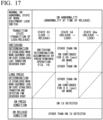
- the switching determination corresponding to the state S4 ⁇ release ⁇ lock> shown in FIG. 17 is established in a case where the last transition of other than "ON” ⁇ "ON” continued for 0.05 [sec] or more ⁇ other than "ON” of the work equipment lock switch 37 is established.
- the switching determination corresponding to the state S6 ⁇ release ⁇ lock> shown in FIG. 18 is established in a case where the last transition of "OFF" ⁇ other than “OFF” continued for 0.05 [sec] or more ⁇ "OFF” of the work equipment lock switch 37 is established.
Landscapes
- Engineering & Computer Science (AREA)
- Mining & Mineral Resources (AREA)
- Civil Engineering (AREA)
- General Engineering & Computer Science (AREA)
- Structural Engineering (AREA)
- Mechanical Engineering (AREA)
- Operation Control Of Excavators (AREA)
- Component Parts Of Construction Machinery (AREA)
Abstract
Description
- The present disclosure relates to a control device, a control method, and a work machine.
- Priority is claimed on
Japanese Patent Application No. 2022-137856, filed August 31, 2022 -
Patent Document 1 discloses a safety device for a work machine in which a position of a gate lock lever that blocks or communicates with a hydraulic flow path of a hydraulic pressure to a hydraulic operating device of work equipment is detected by a plurality of systems such as a combination of two switches and a combination of one switch and one potentiometer. In the safety device disclosed inPatent Document 1, in a case where the position is detected by the combination of two switches, the hydraulic flow path is blocked when input signals from the two switches are different from each other. In addition, in a case where the position is detected by the combination of one switch and one potentiometer, the hydraulic flow path is blocked when the switch is failed, or is blocked or communicated according to a signal from the potentiometer. - Patent Document 1:
Japanese Unexamined Patent Application, First Publication No. 2006-274788 - In the safety device disclosed in
Patent Document 1, in a case where the position of the gate lock lever is detected by the combination of two switches, when the switches are failed, the hydraulic flow path is blocked, and the work equipment cannot be operated. In addition, in a case where the potentiometer is used to detect the position of the gate lock lever, it is difficult to simplify the structure as compared with the combination of two switches. - In a work machine including work equipment, in a case where the operation of the work equipment is stopped in the occurrence of a failure, it may be difficult to move the work machine depending on a posture (position, angle, and the like) of the work equipment at the time of the stop. In order to move the work machine to, for example, a repair factory, it is desirable to secure a function of returning the posture of the work equipment to a state in which the work machine can be moved even in a case where a failure occurs. The degree of maintenance of the minimum function such as a traveling function in a case where a failure occurs is referred to as emergency operability. For example, even in a case where a failure occurs, the posture of the work equipment can be returned to a posture suitable for traveling, and in a case where there is no problem in traveling of the work machine, the emergency operability is good.
- In the safety device disclosed in
Patent Document 1, the safety can be improved by multiplexing the system by using a plurality of systems for detecting the position of the gate lock lever. However, in a case where the position of the gate lock lever is detected by the combination of two switches, the work equipment is stopped in a case where a failure occurs, so that there is a problem that emergency operability is deteriorated. In addition, in the configuration using the potentiometer, there is a problem that it is difficult to simplify the structure. - The present disclosure has been made in view of the above circumstances, and an object of the present disclosure is to provide a control device, a control method, and a work machine capable of achieving both safety and emergency operability in a configuration for locking an operation of the work equipment.
- According to an aspect of the present disclosure, there is provided a control device of a work machine including work equipment, the control device including: a signal input unit configured to input a signal from a first signal line connected to a normally open first switch configured to detect press and release of a momentary operation push button for setting and releasing lock of an operation of the work equipment, and input a signal from a second signal line connected to a normally closed second switch linked to the first switch (hereinafter, a state where the push button is pressed is referred to as ON, and a state where the push button is released is referred to as OFF); and a work equipment lock control unit configured to altemately switch between setting and releasing the lock of the operation of the work equipment in a case where information indicating that the push button is OFF → ON → OFF is obtained from both of the first signal line and the second signal line, and release the lock of the operation of the work equipment only when a predetermined operation is performed on a predetermined operation device of the work equipment when the lock of the operation of the work equipment is set in a case where the information indicating that the push button is OFF → ON → OFF is obtained from only one of the first signal line and the second signal line.
- According to an aspect of the present disclosure, there is provided a control method of a work machine including work equipment, the control method including: a step of inputting a signal from a first signal line connected to a normally open first switch configured to detect press and release of a momentary operation push button for setting and releasing lock of an operation of the work equipment, and inputting a signal from a second signal line connected to a normally closed second switch linked to the first switch (hereinafter, a state where the push button is pressed is referred to as ON, and a state where the push button is released is referred to as OFF); a step of alternately switching between setting and releasing the lock of the operation of the work equipment in a case where information indicating that the push button is OFF → ON → OFF is obtained from both of the first signal line and the second signal line; and a step of releasing the lock of the operation of the work equipment only when a predetermined operation is performed on a predetermined operation device of the work equipment when the lock of the operation of the work equipment is set in a case where the information indicating that the push button is OFF → ON → OFF is obtained from only one of the first signal line and the second signal line.
- According to an aspect of the present disclosure, there is provided a work machine including: work equipment; and a control device including a signal input unit configured to input a signal from a first signal line connected to a normally open first switch configured to detect press and release of a momentary operation push button for setting and releasing lock of an operation of the work equipment, and input a signal from a second signal line connected to a normally closed second switch linked to the first switch (hereinafter, a state where the push button is pressed is referred to as ON, and a state where the push button is released is referred to as OFF), and a work equipment lock control unit configured to alternately switch between setting and releasing the lock of the operation of the work equipment in a case where information indicating that the push button is OFF → ON → OFF is obtained from both of the first signal line and the second signal line, and release the lock of the operation of the work equipment only when a predetermined operation is performed on a predetermined operation device of the work equipment when the lock of the operation of the work equipment is set in a case where information indicating that the push button is OFF → ON → OFF is obtained from only one of the first signal line and the second signal line.
- According to the control device, the control method, and the work machine of the present disclosure, it is possible to achieve both safety and emergency operability in a configuration for locking the operation of the work equipment.
-
- [
FIG. 1 ] A side view showing a work machine according to an embodiment of the present disclosure. - [
FIG. 2 ] A perspective view schematically showing the periphery of a driver's seat according to the embodiment of the present disclosure. - [
FIG. 3 ] A perspective view schematically showing a portion A1 shown inFIG. 2 . - [
FIG. 4 ] A block diagram showing a configuration example of a control system of the work machine according to the embodiment of the present disclosure. - [
FIG. 5 ] A block diagram showing a configuration example of the control system of the work machine according to the embodiment of the present disclosure. - [
FIG. 6 ] A schematic diagram for describing an operation example of a work equipment controller according to the embodiment of the present disclosure. - [
FIG. 7 ] A schematic diagram for describing an operation example of the work equipment controller according to the embodiment of the present disclosure. - [
FIG. 8 ] A state transition diagram showing an operation example of the work equipment controller according to the embodiment of the present disclosure. - [
FIG. 9 ] A schematic diagram for describing an operation example of the work equipment controller according to the embodiment of the present disclosure. - [
FIG. 10 ] A schematic diagram for describing an operation example of the work equipment controller according to the embodiment of the present disclosure. - [
FIG. 11 ] A schematic diagram for describing an operation example of the work equipment controller according to the embodiment of the present disclosure. - [
FIG. 12 ] A schematic diagram for describing an operation example of the work equipment controller according to the embodiment of the present disclosure. - [
FIG. 13 ] A schematic diagram for describing an operation example of the work equipment controller according to the embodiment of the present disclosure. - [
FIG. 14 ] A schematic diagram for describing an operation example of the work equipment controller according to the embodiment of the present disclosure. - [
FIG. 15 ] A schematic diagram for describing an operation example of the work equipment controller according to the embodiment of the present disclosure. - [
FIG. 16 ] A schematic diagram for describing an operation example of the work equipment controller according to the embodiment of the present disclosure. - [
FIG. 17 ] A schematic diagram for describing an operation example of the work equipment controller according to the embodiment of the present disclosure. - [
FIG. 18 ] A schematic diagram for describing an operation example of the work equipment controller according to the embodiment of the present disclosure. - [
FIG. 19 ] A schematic diagram for describing an operation example of the work equipment controller according to the embodiment of the present disclosure. - [
FIG. 20 ] A schematic diagram for describing an operation example of the work equipment controller according to the embodiment of the present disclosure. - [
FIG. 21 ] A timing chart for describing an operation example of the work equipment controller according to the embodiment of the present disclosure. - Embodiments of the present disclosure will be described below with reference to the drawings.
FIG. 1 is a side view showing a work machine according to an embodiment of the present disclosure.FIG. 2 is a perspective view schematically showing the periphery of a driver's seat according to the embodiment of the present disclosure.FIG. 3 is a perspective view schematically showing a portion A1 shown inFIG. 2 .FIGS. 4 and5 are block diagrams showing a configuration example of a control system of the work machine according to the embodiment of the present disclosure.FIGS. 6 and7 are schematic diagrams for describing an operation example of the work equipment controller according to the embodiment of the present disclosure.FIG. 8 is a state transition diagram showing an operation example of a work equipment controller according to the embodiment of the present disclosure.FIGS. 9 to 20 are schematic diagrams for describing operation examples of the work equipment controller according to the embodiment of the present disclosure.FIG. 21 is a timing chart for describing an operation example of the work equipment controller according to the embodiment of the present disclosure. In addition, in each drawing, the same reference numerals are used for the same or corresponding components, and the description thereof will be omitted as appropriate. - As shown in
FIG. 1 , in the present embodiment, a local coordinate system is set in awork machine 1, and a positional relationship of each unit will be described with reference to the local coordinate system. In the local coordinate system, a first axis extending in a right-left direction (vehicle width direction) of thework machine 1 will be defined as an X-axis, a second axis extending in a front-rear direction of thework machine 1 will be defined as a Y-axis, and a third axis extending in an up-down direction of thework machine 1 will be defined as a Z-axis. The X-axis and the Y-axis are orthogonal to each other. The Y-axis and the Z-axis are orthogonal to each other. The Z-axis and the X-axis are orthogonal to each other. A +X-direction is the right direction, and a -X-direction is the left direction. A +Y-direction is the front direction, and a -Y-direction is the rear direction. A +Z-direction is the up direction, and a -Z-direction is the down direction. -
FIG. 1 shows awork machine 1 according to the present embodiment. For example, thework machine 1 according to the present embodiment is a wheel loader. Hereinafter, thework machine 1 will be referred to as awheel loader 1 as appropriate. - As shown in
FIG. 1 , thewheel loader 1 has avehicle body 2, acab 3, a travelingdevice 4, andwork equipment 10. Thewheel loader 1 travels on a work place by using the travelingdevice 4. In the work place, thewheel loader 1 carries out work by using thework equipment 10. Thewheel loader 1 can use thework equipment 10 to carry out the work, such as excavation work, loading work, transport work, and snow removal work. - The
cab 3 is supported by thevehicle body 2. Inside thecab 3, a driver'sseat 31 on which an operator sits, anoperation device 32 to be described later, a display andinput unit 35, and anoutput unit 36 are disposed. Theoperation device 32 includes aboom operation lever 33, abucket operation lever 34, and a workequipment lock switch 37. - The traveling
device 4 includes, for example, a transmission, a drive shaft, a brake, and arotatable wheel 5. The travelingdevice 4 includes, for example, a transmission that has a forward speed stage of 1 to 8 and a backward speed stage of 1 to 4. The smaller the number of the speed stage, the lower the speed. Thewheels 5 support thevehicle body 2. Thewheel loader 1 can travel on a road surface (or ground) RS by the travelingdevice 4. It should be noted thatFIG. 1 shows only afront wheel 5F and arear wheel 5R on a left side. Thefront wheel 5F may be driven by, for example, a hydraulic motor (not shown). - The
work equipment 10 is supported byvehicle body 2. Thework equipment 10 is configured by abucket 12 as an example of a work tool, and amovable support section 17 that changes a position and a posture of thebucket 12. In the example shown inFIG. 1 , themovable support section 17 includes aboom 11, aboom cylinder 13, abucket cylinder 14, abell crank 15, and alink 16. - The
boom 11 is rotatably supported with respect to thevehicle body 2, and moves in the up-down direction according to expansion and contraction of theboom cylinder 13. Theboom cylinder 13 is an actuator that generates power for moving theboom 11, and has one end portion connected to thevehicle body 2 and the other end portion connected to theboom 11. In a case where the operator operates the boom operation lever 33 (FIG. 3 ) included in theoperation device 32, theboom cylinder 13 contracts and extends. As a result, theboom 11 moves in the up-down direction. Theboom cylinder 13 is, for example, a hydraulic cylinder. - The
bucket 12 is a container for an object such as earth, hasbucket teeth 12T, and is a work tool for performing excavation of the object to be excavated such as earth or loading thereof. Thebucket 12 is rotatably connected to theboom 11, and is rotatably connected to one end portion of thelink 16. The other end portion of thelink 16 is rotatably connected to one end portion of thebell crank 15. Thebell crank 15 has a central portion connected to theboom 11 to be rotationally movable, and the other end portion rotatably connected to one end portion of thebucket cylinder 14. The other end portion of thebucket cylinder 14 is rotatably connected to thevehicle body 2. Thebucket 12 is operated by power generated by thebucket cylinder 14. Thebucket cylinder 14 is an actuator that generates power for moving thebucket 12. In a case where the operator operates the bucket operation lever 34 (FIG. 3 ), thebucket cylinder 14 is contracted and extended. As a result, thebucket 12 swings. Thebucket cylinder 14 is, for example, a hydraulic cylinder. Thebucket teeth 12T has a shape of chevron teeth, flat teeth, or the like, and is attached to an end portion of thebucket 12 to be replaceable. -
FIGS. 4 and5 are block diagrams showing a configuration example of a control system of thewheel loader 1 according to the present embodiment. As shown inFIG. 4 , thewheel loader 1 includes apower source 201, a power take off (PTO) 202, ahydraulic pump 203, acontrol valve 200, anoperation device 32, a display andinput unit 35, anoutput unit 36, awork equipment controller 100, anengine controller 300, and a transmission (T/M)controller 400. - The
power source 201 generates a driving force for operating the work machine. An intemal combustion engine and an electric motor are exemplary examples of the power source. In the present embodiment, it is assumed that thepower source 201 is an internal combustion engine (engine). - The
PTO 202 transmits at least a part of the driving force of thepower source 201 to thehydraulic pump 203. ThePTO 202 distributes the driving force of thepower source 201 to the travelingdevice 4 and thehydraulic pump 203. - The
hydraulic pump 203 is driven by thepower source 201, and discharges a hydraulic oil. At least a part of the hydraulic oil discharged from thehydraulic pump 203 is supplied to each of theboom cylinder 13 and thebucket cylinder 14 via thecontrol valve 200. Thecontrol valve 200 receives a predetermined control signal (work equipment EPC signal) from thework equipment controller 100 and controls the flow rate, the pressure, and the direction of the hydraulic oil supplied to each of theboom cylinder 13 and thebucket cylinder 14 from thehydraulic pump 203. Thework equipment 10 is operated by the hydraulic oil from thehydraulic pump 203. - The
operation device 32 is disposed inside thecab 3. Theoperation device 32 is operated by the operator. The operator operates theoperation device 32 to adjust a traveling direction and a traveling speed of thewheel loader 1, switches between forward and rearward movement, and operates thework equipment 10. Theoperation device 32 includes, for example, a steering, a shift lever, an accelerator pedal, a brake pedal, a traveling damper switch, aboom operation lever 33, abucket operation lever 34, and a workequipment lock switch 37. -
FIGS. 2 and3 show configuration examples of theboom operation lever 33, thebucket operation lever 34, and the workequipment lock switch 37 according to the present embodiment. Theboom operation lever 33 and thebucket operation lever 34 may have the same configuration.FIG. 3 shows a case where tilt positions of theboom operation lever 33 and thebucket operation lever 34 are neutral positions. Thebucket operation lever 34 is tilted in the front-rear direction around the neutral position as indicated by an arrow A21 and an arrow A22 inFIG. 3 . Similarly, theboom operation lever 33 is tilted in the front-rear direction with the neutral position as a center. Theboom operation lever 33 and thebucket operation lever 34 have a mechanism that automatically returns the position of the operation lever to the neutral position in a state where a certain or more operation force is not applied to the operation lever. - The
boom operation lever 33 is an operation lever for operating the posture of theboom 11. In a case where theboom operation lever 33 is tilted in the rear direction, theboom 11 moves in the upward direction. In a case where theboom operation lever 33 is tilted in the front direction, theboom 11 moves in the downward direction. The movement speed is changed according to a tilt amount of theboom operation lever 33. The larger the tilt amount, the higher the speed. Thebucket operation lever 34 is an operation lever for operating the posture of thebucket 12. In a case where thebucket operation lever 34 is tilted in the rear direction, thebucket 12 is moved in a tilt direction (a direction in which thebucket teeth 12T faces upward as shown inFIG. 1 ). In a case where thebucket operation lever 34 is tilted in the front direction, thebucket 12 is moved in a dump direction (direction in which thebucket teeth 12T shown inFIG. 1 faces downward). The movement speed is changed according to the tilt amount of thebucket operation lever 34. The larger the tilt amount, the higher the speed. Theboom operation lever 33 and thebucket operation lever 34 include one or a plurality of stroke sensors therein, detect the tilt amount of the operation lever, and output a detection signal (work equipment lever signal inFIG. 5 ) indicating the detection result as an analog voltage value. - The work
equipment lock switch 37 is a push button switch (push button according to the present disclosure) for setting and releasing the lock of the operation of thework equipment 10. The workequipment lock switch 37 is a momentary operation push button switch. That is, the workequipment lock switch 37 is turned on only while the button is being pressed by the hand or the like, and is returned to the off state in a case where the hand or the like is separated from the button. In addition, as shown inFIGS. 4 and5 , the workequipment lock switch 37 includes a work equipment lock switch (SW)1 (371) and a work equipment lock switch (SW)2 (372). - The work equipment lock SW1 (371) is a normally open switch (first switch according to the present disclosure) that detects the press and release of the work
equipment lock switch 37. The work equipment lock SW1 (371) is turned on while the button is being pressed, and is turned off in a case where the button is released. The work equipment lock SW2 (372) is a normally closed switch (second switch according to the present disclosure) that detects the press and release of the workequipment lock switch 37 linked to the work equipment lock SW1 (371). The work equipment lock SW2 (372) is turned off while the button is being pressed, and is turned on in a case where the button is released. - In addition, the work
equipment lock switch 37 includes adisplay lamp 373 consisting of a light emitting diode (LED). Thedisplay lamp 373 is controlled by thework equipment controller 100 to be turned on in a state where thework equipment 10 is not operated, that is, in a state where the operation of thework equipment 10 is locked (in the present embodiment, this state is also referred to as a state where the work equipment is set to be locked), and to be turned off in a state where thework equipment 10 can be operated, that is, in a state where the lock of the operation of thework equipment 10 is released. - In the present embodiment, a state where the work equipment lock switch 37 (push button) is pressed is referred to as ON, and a state where the work equipment lock switch 37 (push button) is released is referred to as OFF. In addition, the work
equipment lock switch 37 may be simply referred to as "SW". For example, "SW normality" means a state in which the work equipment lock SW1 (371) and the work equipment lock SW2 (372) are normally operated. In addition, "SW abnormality" means a state in which the ground fault, power supply fault, or disconnection failure is generated in any of the work equipment lock SW1 (371) or the work equipment lock SW2 (372). - In addition, as shown in
FIG. 5 , one terminal of the work equipment lock SW1 (371) is connected to the DC power supply (24 V in the present embodiment), and the other terminal is connected to thework equipment controller 100. A signal line that connects the other terminal of the work equipment lock SW1 (371) to an input circuit (not shown) in thework equipment controller 100 is a first signal line, and a signal name on the first signal line is the work equipment lock SW1. One terminal of the work equipment lock SW2 (372) is connected to the DC power supply, and the other terminal is connected to thework equipment controller 100. A signal line that connects the other terminal of the work equipment lock SW2 (372) to an input circuit (not shown) in thework equipment controller 100 is a second signal line, and a signal name on the second signal line is the work equipment lock SW2. The first signal line and the second signal line are pulled down through a predetermined resistor in thework equipment controller 100. - In addition, an anode of an LED constituting the work
equipment lock switch 37 is connected to an output terminal (signal name: work equipment lock indicator) of thework equipment controller 100, and a cathode is connected to the ground. - In addition, the display and
input unit 35 shown inFIG. 4 is configured with a combination of an input device and a display device, an input display device such as a touch panel, and the like. The operator inputs, for example, a set value or the like in the control of thework equipment 10 or displays information indicating the content in a case where a failure or the like occurs, using the display andinput unit 35. The display andinput unit 35 displays predetermined information in response to the monitor display indicator signal received from thework equipment controller 100. In addition, theoutput unit 36 includes a display device, a synthetic voice, an output device of an alarm sound or a notification sound, a display lamp such as a warning lamp, and the like, and outputs predetermined information. - The
engine controller 300 shown inFIG. 4 controls thepower source 201 according to an operation of an accelerator pedal (not shown) provided in theoperation device 32. In addition, theengine controller 300 has an auto-idle stop function of automatically stopping the engine in a case where the idling state is continued for an idling time set by the operator. As shown inFIG. 5 , theengine controller 300 transmits an idle step status signal indicating whether or not thepower source 201 is stopped by the auto-idle stop function, to thework equipment controller 100. - The T/
M controller 400 shown inFIG. 4 controls a transmission (not shown) provided in the travelingdevice 4 according to an operation of a shift lever (not shown) provided in theoperation device 32. In addition, as shown inFIG. 5 , the T/M controller 400 transmits a signal (travel damper SW signal) indicating whether or not a traveling damper function is operating, a signal indicating the vehicle speed, a signal requesting the lock of thework equipment 10, and the like to thework equipment controller 100. The traveling damper function is a function of reducing the vibration caused by traveling by connecting theboom cylinder 13 to an accumulator (not shown) in thecontrol valve 200 during traveling to control the pressure accumulation of the accumulator. In addition, the signal for requesting the lock of thework equipment 10 is generated, for example, in a case where it is necessary to give priority to the traveling side over the work of thework equipment 10 in a case where thework equipment 10 is traveling on a steep slope or the like. - The
work equipment controller 100 is formed using, for example, a field programmable gate array (FPGA) or a microcomputer that includes a processor, a main storage device, an auxiliary storage device, an input/output device, and the like. Thework equipment controller 100 includes, as a functional configuration constituted by hardware or a combination of hardware and software such as a program, a workequipment control unit 101, asignal input unit 102, a work equipmentlock control unit 103, and analarm activation unit 104. Thework equipment controller 100 is an example of a control device according to the present disclosure. - The work
equipment control unit 101 drives and controls theboom cylinder 13, thebucket cylinder 14, and the like by outputting a work equipment electric pressure control (EPC) signal in response to the work equipment lever signal and the like output from theoperation device 32 and controlling thecontrol valve 200.FIG. 5 shows a configuration of a part of thecontrol valve 200. In addition, the work equipment EPC signal indicates one of the plurality of work equipment EPC signals. Thepressure control valve 211 controls hydraulic oil supplied to theboom cylinder 13, thebucket cylinder 14, and the like by variably controlling an operation of asolenoid 211s according to the work equipment EPC signal. - In addition, the work
equipment control unit 101 determines whether or not there is an abnormality in the work equipment lever according to the work equipment lever signal or the like output by theoperation device 32. In a case where it is determined that there is the abnormality, the workequipment control unit 101 stops the drive of thework equipment 10 or implements the function restriction of limiting the drive speed of thework equipment 10. - The
signal input unit 102 repeatedly inputs the work equipment lock SW1 signal and the work equipment lock SW2 signal, for example, at a predetermined cycle. That is, thesignal input unit 102 inputs the work equipment lock SW1 signal from a signal line (referred to as a first signal line) connected to the normally open work equipment lock SW1 (first switch) 371 that detects the press and release of the workequipment lock switch 37, which is a momentary operation push button for setting and releasing the lock of the operation of thework equipment 10, and inputs the work equipment lock SW2 signal from a signal line (referred to as a second signal line) connected to the work equipment lock SW2 (second switch) 372 of the normally closed type linked to the work equipment lock SW1. That is, thework equipment controller 100 has a step of inputting a signal from the first signal line connected to the normally open first switch that detects the press and release of the momentary operation push button for setting and releasing the lock of the operation of thework equipment 10 and is connected to the first switch, and inputting the signal from the second signal line connected to the normally closed second switch linked to the first switch. - The work equipment
lock control unit 103 outputs a work equipment lock solenoid (SOL) signal in response to the work equipment lock SW1 signal, the work equipment lock SW2 signal, and the like input from the workequipment lock switch 37, and turns on or off thedirection control valve 212 to block or supply the hydraulic oil supplied to theboom cylinder 13, thebucket cylinder 14, and the like. For example, the work equipment lock SOL signal is turned on to apply a direct current of 24 V to asolenoid 212s of thedirection control valve 212 to block the hydraulic oil, and the work equipment lock SOL signal is turned off to be the open state to supply the hydraulic oil. Here, the state in which the hydraulic oil is blocked is a state in which thework equipment 10 is locked (state in which the lock is set), and the state in which the hydraulic oil is supplied is a state in which the lock of thework equipment 10 is released. - In a case where information indicating that the work equipment lock switch 37 (push button) is OFF → ON → OFF is obtained from both of the first signal line and the second signal line, the work equipment
lock control unit 103 altemately switches between setting and releasing the lock of the operation of thework equipment 10, and in a case where information indicating that the work equipment lock switch 37 (push button) is OFF → ON → OFF is obtained from only one of the first signal line and the second signal line, the work equipmentlock control unit 103 releases the lock of the operation of thework equipment 10 only when a predetermined operation is performed on apredetermined operation device 32 of thework equipment 10 when the lock of the operation of thework equipment 10 is set. The predetermined operation can include, for example, an operation by a combination of predetermined operations for a plurality of operation levers included in theoperation device 32. The predetermined operation can include, for example, an operation of simultaneously performing an operation of driving thebucket 12 at a predetermined speed or more in the dump direction with respect to thebucket operation lever 34 for driving thebucket 12 in the dump direction and the tilt direction and an operation of driving theboom 11 at the predetermined speed or more in the lowering direction with respect to theboom operation lever 33 for driving theboom 11 in the up-down direction. That is, in a case where information indicating that the push button is OFF → ON → OFF is obtained from both of the first signal line and the second signal line, thework equipment controller 100 has a step of altemately switching the setting and the release of the lock of the operation of thework equipment 10, and in a case where information indicating that the push button is OFF → ON - OFF is obtained from only one of the first signal line and the second signal line, thework equipment controller 100 has a step of releasing the lock of the operation of thework equipment 10 only in a case where a predetermined operation is performed on a predetermined operation device of thework equipment 10 when the lock of the operation of thework equipment 10 is set. - In a case where the work
equipment lock switch 37 is not OFF → ON → OFF in a state where the lock of thework equipment 10 is released, when a predetermined condition for automatically setting the lock of thework equipment 10 is established, the work equipmentlock control unit 103 sets the lock of thework equipment 10 when thework equipment 10 is controlled to be in a stop state. In a case where the lock of thework equipment 10 is automatically locked (set to the lock) from the release without the operation of the operator, the lock is set when thework equipment 10 is controlled to be in the stop state. According to this configuration, it is possible to prevent thework equipment 10 from being suddenly stopped when the automatic locking is performed, and for example, it is possible to prevent a large forward fall or an impact from being generated. - In a case where information indicating the occurrence of a predetermined failure is obtained from the first signal line or the second signal line, the
alarm activation unit 104 reports that fact to the display andinput unit 35, theoutput unit 36, and the like. - First, with reference to
FIGS. 6 to 9 , the operation determination of turning on or off the workequipment lock switch 37 based on the work equipment lock SW1 signal and the work equipment lock SW2 signal and the determination of whether or not there is an abnormality (hereinafter, referred to as an abnormality determination) will be described.FIG. 6 shows a correspondence relationship between a combination of a state of "Hi" (high level) or "Lo" (low level) of the work equipment lock SW1 signal and a state of "Hi" or "Lo" of the work equipment lock SW2 signal, and results of the operation determination and the abnormality determination. In a normal case, one of the work equipment lock SW1 signal and the work equipment lock SW2 signal is "Hi", and the other is "Lo". In addition, a case where both of the work equipment lock SW1 signal and the work equipment lock SW2 signal are "Hi" ("abnormal Hi") or both of the work equipment lock SW1 signal and the work equipment lock SW2 signal are "Lo" ("abnormal Lo") is an abnormal case. -
FIG. 7 shows the classification of the operation states based on the work equipment lock SW1 signal and the work equipment lock SW2 signal as the operation states A to E.FIG. 7 shows a correspondence relationship among the normal or abnormal states, whether or not it is in a normal state and the content of the abnormality when the state is the abnormal state, a time-series signal (the work equipment lock SW1 signal and the work equipment lock SW2 signal) when the operator performs the normal ON/OFF switching operation (the operation of pressing and releasing the work equipment lock switch 37), a state recognition of the workequipment lock switch 37 of thework equipment controller 100, the presence or absence of the error report by thealarm activation unit 104, and the processing contents of whether or not the work equipmentlock control unit 103 executes the switching between the setting and the release of the lock state, in the operation states A to E. - The operation state A is an SW normality and is normal, and with respect to "release" → "press" → "release" of the SW, the work equipment lock SW1 signal of normally open (N.O.) is set to "Lo" → "Hi" → "Lo", and the work equipment lock SW2 signal of normally closed (N.C.) is set to "Hi" - "Lo" → "Hi". In addition, the state recognition is "OFF" → "ON" → "OFF". However, since chattering occurs at the time of switching of the switch, the actual signal is "abnormal Hi" or "abnormal Lo" for a short time. In this case, the error report is not performed, and switching between the release and setting of the lock is executed.
- The operation state B is an SW abnormality (abnormality at the time of press), and the content of the abnormality is disconnection or a ground failure of the normally open work equipment lock SW1 (371). With respect to "release" → "press" → "release" of the SW, the work equipment lock SW1 signal of normal open (N.O.) is fixed to "Lo", and the work equipment lock SW2 signal of normal close (N.C.) is set to "Hi" → "Lo" → "Hi". Further, the state recognition is "OFF" → "abnormal Lo" → "OFF". In this case, the error report is performed, and the switching between the release and setting of the lock is executed.
- The abnormality at the time of press is an abnormality that can be detected in a state where the work
equipment lock switch 37 is pressed. In addition, the abnormality at the time of release is an abnormality that can be detected in a state where the workequipment lock switch 37 is released. - The operation state C is an SW abnormality (abnormality at the time of release), and the content of the abnormality is a power supply failure of the normally open work equipment lock SW1 (371). With respect to "release" → "press" → "release" of the SW, the work equipment lock SW1 signal of normal open (N.O.) is fixed to "Hi", and the work equipment lock SW2 signal of normal close (N.C.) is set to "Hi" → "Lo" → "Hi". Further, the state recognition is "abnormal Hi" → "ON" → "abnormal Hi". In this case, the error report is performed, and the switching between the release and setting of the lock is executed.
- The operation state D is the SW abnormality (abnormality at the time of release), and the content of the abnormality is a ground fault or disconnection failure of the normally closed work equipment lock SW2 (372). With respect to "release" → "press" → "release" of the SW, the work equipment lock SW1 signal of normal open (N.O.) is set to "Lo" → "Hi" → "Lo", and the work equipment lock SW2 signal of normal close (N.C.) is fixed to "Lo". Further, the state recognition is "abnormal Lo" - "ON" → "abnormal Lo". In this case, the error report is performed, and the switching between the release and setting of the lock is executed.
- The operation state E is the SW abnormality (abnormality at the time of press), and the content of the abnormality is a power supply failure of the normally closed work equipment lock SW2 (372). With respect to "release" → "press" → "release" of the SW, the work equipment lock SW1 signal of normal open (N.O.) is "Lo" → "Hi" → "Lo", and the work equipment lock SW2 signal of normal close (N.C.) is fixed to "Hi". Further, the state recognition is "OFF" → "abnormal Hi" → "OFF". In this case, the error report is performed, and the switching between the release and setting of the lock is executed.
- As described with reference to
FIG. 7 , even in a case where a failure occurs in any of the two switches for detecting the press and release of the workequipment lock switch 37, when the workequipment lock switch 37 is operated in the order of "release" → "press" → "release", the operation of "release" → "press" → "release" can be detected from the state at the time of "press" and the state before and after "press". Therefore, the setting and release of the lock of thework equipment 10 can be performed according to the intention of the operator. In addition, in a case where the occurrence of an abnormality is detected, the operator or the like can be notified that repair is necessary by reporting that fact. Therefore, it is possible to prevent further progress of the failure. - It should be noted that the determination of whether or not to execute the switching between the setting and the release of the lock state is not limited to being performed based on only the operation state of the work
equipment lock switch 37, and can be performed, for example, in consideration of another operation state or the like of thework machine 1. Examples thereof will be described below. - An operation example of the work equipment
lock control unit 103 will be described with reference to a state transition diagram of the work equipment lock state shown inFIG. 8 .FIGS. 9 to 20 show examples of transition conditions of states in the state transition diagram shown inFIG. 8 . The initial state is a time of start of the work machine 1 (a time of turning on the key), and the initial state after the start is a state S1. - A state transition diagram shown in
FIG. 8 includes states S1, S2, S2a, S3, S4, S5, and S6. Each of the states S1 to S6 is classified into one of the lock state (set state) S11 or the release state S12. The states S1, S3, and S5 belong to the lock state S11, and in the states S1, S3, and S5, the work equipmentlock control unit 103 locks thework equipment 10. In addition, the state S2, the state S2a, the state S4, and the state S6 belong to the release state S12, and in the state S2, the state S2a, the state S4, and the state S6, the work equipmentlock control unit 103 releases the lock of thework equipment 10. - In addition, each of the states S1 to S6 is classified into any of a SW normal state S21, a SW abnormal (abnormal at the time of release) state S22, or a SW abnormal (abnormal at the time of press) state S23. The SW normal state S21 includes the state S1, the state S2, and the state S2a. The SW abnormal (abnormal at the time of release) state S22 includes the state S3 and the state S4. The SW abnormal (abnormal at the time of press) state S23 includes the state S5 and the state S6.
- In a case where a
condition 1 is established in the state S1, the state transitions to the state S2. In a case where acondition 3 is established in the state S1, the state transitions to the state S3. In a case where acondition 2 is established in the state S2, the state transitions to the state S1. In a case where acondition 6 is established in the state S2, the state transitions to a state S2a. In a case where acondition 7 is established in the state S2a, the state transitions to the state S1. - In addition, in a case where a
condition 5 is established in the state S3, the state transitions to the state S4. In a case where acondition 4 is established in the state S3, the state transitions to a state S5. In a case where thecondition 2 is established in the state S4, the state transitions to the state S3. In a case where thecondition 4 is established in the state S4, the state transitions to the state S6. - In addition, in a case where the
condition 5 is established in the state S5, the state transitions to the state S6. In a case where thecondition 2 is established in the state S6, the state transitions to the state S5. -
FIGS. 9 to 15 show examples of the contents of theconditions 1 to 7 shown inFIG. 8 .FIGS. 16 to 18 show examples of conditions of switching determination, conditions of long press determination, the SW press condition, and SW release conditions, which are conditions including some of theconditions 1 to 7. In addition,FIG. 19 shows an example of the content of the switching determination accompanied by the predetermined operation shown inFIG. 17 . In addition,FIG. 20 shows an example of the content of the switching determination accompanied by the predetermined operation shown inFIG. 18 . - As shown in
FIG. 9 , thecondition 1 is established in which the switching determination is established (C11), all levers of the work equipment are neutral (C12), and there is no work equipment EPC hot short error (C13). The switching determination is established (C11) in a case where the last transition of "OFF" → "ON" continued for 0.05 [sec] or more → "OFF" of the workequipment lock switch 37 of the switching determination corresponding to the state S1 <lock → release> is established, as shown inFIG. 16 . In addition, there is no work equipment EPC hot short error (C13) means that the output terminal of the work equipment EPC signal does not have a power supply failure or a short circuit failure. Thecondition 1 is a logical product (AND) of the conditions C11 to C13. - As shown in
FIG. 10 , thecondition 2 is established in which the switching determination is established (C21), the long press determination is established (C22), or the work equipment EPC hot short error is detected (any one is detected) (C23). Thecondition 2 is a logical sum (OR) of the condition C21 to the condition C23. With respect to the establishment (C21) of the switching determination, the switching determination corresponding to the state S2 <release → lock> is as shown inFIG. 16 , the switching determination corresponding to the state S4 <release → lock> is as shown inFIG. 17 , and the switching determination corresponding to the state S6 <release → lock> is as shown inFIG. 18 . The switching determination corresponding to the state S2 <release → lock> shown inFIG. 16 is established in a case where the last transition of "OFF" → "ON" continued for 0.05 [sec] or more → "OFF" of the workequipment lock switch 37 is established. The switching determination corresponding to the state S4 <release → lock> shown inFIG. 17 is established in a case where the last transition of other than "ON" → "ON" continued for 0.05 [sec] or more → other than "ON" of the workequipment lock switch 37 is established. The switching determination corresponding to the state S6 <release → lock> shown inFIG. 18 is established in a case where the last transition of "OFF" → other than "OFF" continued for 0.05 [sec] or more → "OFF" of the workequipment lock switch 37 is established. - Further, with respect to the establishment (C22) of the long press determination, the long press determination corresponding to the state S2 <release → lock> is as shown in
FIG. 16 , the long press determination corresponding to the state S4 <release → lock> is as shown inFIG. 17 , and the long press determination corresponding to the state S6 <release → lock> is as shown inFIG. 18 . The long press determination corresponding to the state S2 <release → lock> shown inFIG. 16 is established in a case where the "OFF" → "ON" continued for 0.5 [sec] or more of the workequipment lock switch 37 is established. The long press determination corresponding to the state S4 <release → lock> shown inFIG. 17 is established in a case where other than "ON" → "ON" continued for 0.5 [sec] or more of the workequipment lock switch 37 is established. The long press determination corresponding to the state S6 <release → lock> shown inFIG. 18 is established in a case where "OFF" → other than "OFF" continued for 0.5 [sec] or more of the workequipment lock switch 37 is established. - Since the
condition 2 includes the establishment of the long press determination (C22) in addition to the establishment of the switching determination (C21), the operation of the workequipment lock switch 37 limited to a case where the switching determination is established (C11) in thecondition 1 includes the long press operation. - As shown in
FIG. 11 , thecondition 3 is that the failure (disconnection, ground fault, or power supply fault) of the workequipment lock switch 37 is detected (C31). - As shown in
FIG. 12 , thecondition 4 is that the SW state OFF is detected (C41) for 0.05 [sec]. Thecondition 4 is a condition for determining whether or not the abnormality is the abnormality at the time of press. - As shown in
FIG. 13 , thecondition 5 is established in a case where the switching determination is established (C51), all the predetermined work equipment levers (for example, theboom operation lever 33 and the bucket operation lever 34) are normal (C52), and there is no work equipment EPC hot short error (C53). The establishment (C51) of the switching determination is the condition of the switching determination shown inFIG. 19 corresponding to the state S3 <lock → release> shown inFIG. 17 or the condition of the switching determination shown inFIG. 20 corresponding to the state S5 <lock → release> shown inFIG. 18 . - The condition of the switching determination shown in
FIG. 19 is established in a case where the transition of astage 1 → astage 2 → astage 3 → astage 4 → "release" is made. The transition from thestage 1 to thestage 2 is made in a case where the condition in which the predetermined operation is performed and other than ON of the workequipment lock switch 37 is 5 [sec] or more is established. The predetermined operation is an operation in which the tilt amount of theboom operation lever 33 in the front direction is 80% or more of the full stroke and the tilt amount of thebucket operation lever 34 in the front direction is 90% or more of the full stroke. In a case where theboom operation lever 33 is pushed down in the front direction by 80% or more, thebucket operation lever 34 is pushed down in the front direction by 90% or more, and the state where the workequipment lock switch 37 is not pressed is continued for 5 seconds or more, the transition from thestage 1 to thestage 2 is performed. In a case where the predetermined operation is not established in thestage 2, the transition is made from thestage 2 to thestage 1. - In the
stage 2, in a case where the state where the workequipment lock switch 37 is pressed is continued for 0.05 seconds or more, the transition to thestage 3 is performed. In a case where the workequipment lock switch 37 is other than ON in thestage 3, the transition to thestage 2 is performed. - In a case where a state in which all levers of the work equipment are neutral in the
stage 3 is continued for 0.5 seconds or more, the transition to stage 4 is performed. In a case where the workequipment lock switch 37 is other than ON in thestage 4, the lock of thework equipment 10 is released. In a case where any of all levers of the work equipment is other than neutral instage 4, the control proceeds tostage 3. - As shown in
FIG. 21 , in the condition shown inFIG. 19 , a predetermined operation is started at time t1 from a state where the operation lever is neutral and the operator releases the work equipment lock switch 37 (operator operation release), the workequipment lock switch 37 is pressed by the operator at time t2 when the predetermined operation is continued (operator operation press), the operation lever is neutral at time t3 when the state where the workequipment lock switch 37 is pressed by the operator is continued, and thereafter, the lock is released at time t4 when the workequipment lock switch 37 is released by the operator. Since the return condition from each stage is set under the condition shown inFIG. 19 , the order in which each condition is established is also defined as shown inFIG. 21 . - The condition for the switching determination shown in
FIG. 20 is established in a case where the transition is made from thestage 1 to thestage 2 to thestage 3 to thestage 4 to the "release". The transition from thestage 1 to thestage 2 is made in a case where the predetermined operation is performed and the condition that the workequipment lock switch 37 is OFF for 5 [sec] or more is established. The predetermined operation is the same as the predetermined operation described with reference toFIG. 19 . In a case where the predetermined operation is not established in thestage 2, the transition is made from thestage 2 to thestage 1. - In the
stage 2, in a case where the workequipment lock switch 37 is other than OFF and is continued for 0.05 seconds or more, the transition to thestage 3 is performed. In a case where the workequipment lock switch 37 is OFF in thestage 3, the transition to thestage 2 is performed. - In a case where a state in which all levers of the work equipment are neutral in the
stage 3 is continued for 0.5 seconds or more, the transition to stage 4 is performed. In a case where the workequipment lock switch 37 is OFF in thestage 4, the lock of thework equipment 10 is released. In a case where any of all levers of the work equipment is other than neutral instage 4, the control proceeds tostage 3. - The conditions shown in
FIG. 20 are also defined in the same manner as the conditions shown inFIG. 19 in terms of the order in which each condition is established. - Meanwhile, as shown in
FIG. 14 , thecondition 6 is established in which the SW state is OFF → other than ON/OFF is continued for 0.5 [sec] or more (C61), or the SW state is OFF → other than ON/OFF is continued for 0.05 [sec] or more (C62). - As shown in
FIG. 15 , thecondition 7 is established in which a target flow rate of all the work equipment EPC is 0 [%] (C71) or the work equipment EPC hot short error is detected (any one) (C72). Thecondition 7 is a condition that thework equipment 10 is stopped or control for stopping thework equipment 10 is performed. - The state S2a is a state of a preparation stage in a case where the
work equipment 10 is automatically locked (the lock is automatically set) from a state where the lock of thework equipment 10 is released. In a state where the lock of thework equipment 10 is released, thework equipment 10 can be operated. Therefore, depending on the timing at which thework equipment 10 is locked, the operation of thework equipment 10 is suddenly stopped, and for example, there is a possibility that the balance of thework machine 1 is inappropriate. Therefore, in a case where the condition (condition 6) under which the lock is automatically performed is established, the state is once transitioned to the state S2a from the state S2, and the state is further transitioned to thestate 1 when thecondition 7 is established, so that thework equipment 10 is safely locked. - According to the present embodiment, it is possible to improve safety in the configuration for locking the operation of the work equipment by multiplexing two systems of switches that detect the operation of providing the instruction to switch between the setting and the release of the lock of the
work equipment 10. In addition, even in a case where one of the switches to be detected is failed, the operation of instructing the operator to switch can be detected by the operation of the normal switch, so that the lock can be released and the emergency operability is not deteriorated. Further, in a case where the switch is failed, the operation of releasing the lock is added under a condition that a predetermined operation is accompanied with the operation of the switch on theoperation device 32. Therefore, it is possible to ensure safety by reducing the possibility of unintentional release even in a case where one system fails. - Although the embodiments of the present invention have been described above in detail with reference to the drawings, the specific configuration is not limited to the above embodiments, and design modifications and the like are included within the scope of the gist of the present invention. Furthermore, some or all of the programs executed by the computer in the above embodiments can be distributed via a computer-readable recording medium or a communication line.
- For example, the
wheel loader 1 may be remotely operable. In this case, a part or all of thework equipment controller 100 and theoperation device 32 can be provided, for example, at a place in which the remote operation is performed. - In addition, for example, the work machine (or work vehicle) is not limited to the wheel loader. For example, another work machine such as a hydraulic excavator can be used. In addition, the work tool is not limited to the bucket. The work tool may be, for example, a fork, a bale grab, or the like that is attached to the wheel loader to be replaceable, as an attachment.
- The work equipment controller 100 (control device) described in the above embodiment is understood as follows, for example.
-
- (1) A control device (work equipment controller 100) is a control device of a work machine 1 including work equipment 10, and the control device includes: a signal input unit 102 configured to input a signal from a first signal line connected to a normally open first switch (work equipment lock SW1 (371)) configured to detect press and release of a momentary operation push button (work equipment lock switch 37) for setting and releasing lock of an operation of the work equipment, and input a signal from a second signal line connected to a normally closed second switch (work equipment lock SW2 (372)) linked to the first switch (hereinafter, a state where the push button is pressed is referred to as ON, and a state where the push button is released is referred to as OFF); and a work equipment lock control unit 103 configured to altemately switch between setting and releasing the lock of the operation of the work equipment in a case where information indicating that the push button is OFF → ON → OFF is obtained from both of the first signal line and the second signal line, and release the lock of the operation of the work equipment only when a predetermined operation is performed on a predetermined operation device 32 of the work equipment when the lock of the operation of the work equipment is set in a case where the information indicating that the push button is OFF → ON → OFF is obtained from only one of the first signal line and the second signal line.
- (2) The control device according to (1) further includes an
alarm activation unit 104 configured to, when information indicating an occurrence of a predetermined fault is obtained from the first signal line or the second signal line, report the fact. - (3) The control device according to (1) or (2), in which, in a case where the push button is not OFF → ON → OFF in a state where the lock of the work equipment is released, when a predetermined condition for automatically setting the lock of the work equipment is established, the work equipment lock control unit sets the lock of the work equipment when the work equipment is controlled to be in a stop state.
- (4) The control device according to any one of (1) to (3), in which the operation device includes a plurality of operation levers (
boom operation lever 33 and bucket operation lever 34), and the predetermined operation includes an operation by a combination of predetermined operations for the plurality of operation levers. - (5) The control device according to any one of (1) to (4), in which the work equipment includes a
bucket 12 that is a container for an object and aboom 11 configured to drive the bucket in an up-down direction, the operation device includes abucket operation lever 34 configured to drive the bucket in a dump direction and a tilt direction and aboom operation lever 33 configured to drive the boom in the up-down direction, and the predetermined operation includes an operation of simultaneously performing an operation for the bucket operation lever that drives the bucket in the dump direction at a predetermined speed or more and an operation for the boom operation lever that drives the boom in a lowering direction at a predetermined speed or more. - According to the control device, the control method, and the work machine of the present disclosure, it is possible to achieve both safety and emergency operability in a configuration for locking the operation of the work equipment.
-
- 1 Wheel loader (work machine)
- 2 Vehicle body
- 3 Cab
- 4 Traveling device
- 5 Wheel
- 6 Tire
- 10 Work equipment
- 11 Boom
- 12 Bucket (work tool)
- 12T Bucket teeth
- 13 Boom cylinder
- 14 Bucket cylinder
- 15 Bell crank
- 16 Link
- 17 Movable support section
- 32 Operation device
- 33 Boom operation lever
- 34 Bucket operation lever
- 37 Work equipment lock switch
- 371 Work equipment lock SW1
- 372 Work equipment lock SW2
- 100 Work equipment controller (control device)
- 101 Work equipment control unit
- 102 Signal input unit
- 103 Work equipment lock control unit
- 104 Alarm activation unit
Claims (7)
- A control device of a work machine including work equipment, the control device comprising:a signal input unit configured to input a signal from a first signal line connected to a normally open first switch configured to detect press and release of a momentary operation push button for setting and releasing lock of an operation of the work equipment, and input a signal from a second signal line connected to a normally closed second switch linked to the first switch (hereinafter, a state where the push button is pressed is referred to as ON, and a state where the push button is released is referred to as OFF); anda work equipment lock control unit configured to alternately switch between setting and releasing the lock of the operation of the work equipment in a case where information indicating that the push button is OFF → ON → OFF is obtained from both of the first signal line and the second signal line, and release the lock of the operation of the work equipment only when a predetermined operation is performed on a predetermined operation device of the work equipment when the lock of the operation of the work equipment is set in a case where the information indicating that the push button is OFF → ON → OFF is obtained from only one of the first signal line and the second signal line.
- The control device according to Claim 1, further comprising an alarm activation unit configured to, when information indicating an occurrence of a predetermined fault is obtained from the first signal line or the second signal line, report the fact.
- The control device according to Claim 2, wherein, in a case where the push button is not OFF → ON → OFF in a state where the lock of the work equipment is released, when a predetermined condition for automatically setting the lock of the work equipment is established, the work equipment lock control unit sets the lock of the work equipment when the work equipment is controlled to be in a stop state.
- The control device according to any one of Claims 1 to 3, wherein the operation device includes a plurality of operation levers, and
the predetermined operation includes an operation by a combination of predetermined operations for the plurality of operation levers. - The control device according to Claim 4, wherein the work equipment includes a bucket that is a container for an object and a boom configured to drive the bucket in an up-down direction,the operation device includes a bucket operation lever configured to drive the bucket in a dump direction and a tilt direction and a boom operation lever configured to drive the boom in the up-down direction, andthe predetermined operation includes an operation of simultaneously performing an operation for the bucket operation lever that drives the bucket in the dump direction at a predetermined speed or more and an operation for the boom operation lever that drives the boom in a lowering direction at a predetermined speed or more.
- A control method of a work machine including work equipment, the control method comprising:a step of inputting a signal from a first signal line connected to a normally open first switch configured to detect press and release of a momentary operation push button for setting and releasing lock of an operation of the work equipment, and inputting a signal from a second signal line connected to a normally closed second switch linked to the first switch (hereinafter, a state where the push button is pressed is referred to as ON, and a state where the push button is released is referred to as OFF);a step of altemately switching between setting and releasing the lock of the operation of the work equipment in a case where information indicating that the push button is OFF → ON → OFF is obtained from both of the first signal line and the second signal line; anda step of releasing the lock of the operation of the work equipment only when a predetermined operation is performed on a predetermined operation device of the work equipment when the lock of the operation of the work equipment is set in a case where the information indicating that the push button is OFF → ON → OFF is obtained from only one of the first signal line and the second signal line.
- A work machine comprising:work equipment; anda control device includinga signal input unit configured to input a signal from a first signal line connected to a normally open first switch configured to detect press and release of a momentary operation push button for setting and releasing lock of an operation of the work equipment, and input a signal from a second signal line connected to a normally closed second switch linked to the first switch (hereinafter, a state where the push button is pressed is referred to as ON, and a state where the push button is released is referred to as OFF), anda work equipment lock control unit configured to alternately switch between setting and releasing the lock of the operation of the work equipment in a case where information indicating that the push button is OFF → ON → OFF is obtained from both of the first signal line and the second signal line, and release the lock of the operation of the work equipment only when a predetermined operation is performed on a predetermined operation device of the work equipment when the lock of the operation of the work equipment is set in a case where information indicating that the push button is OFF → ON → OFF is obtained from only one of the first signal line and the second signal line.
Applications Claiming Priority (2)
| Application Number | Priority Date | Filing Date | Title |
|---|---|---|---|
| JP2022137856A JP2024033930A (en) | 2022-08-31 | 2022-08-31 | Control device, control method and working machine |
| PCT/JP2023/024646 WO2024048063A1 (en) | 2022-08-31 | 2023-07-03 | Control device, control method, and work machine |
Publications (2)
| Publication Number | Publication Date |
|---|---|
| EP4495334A1 true EP4495334A1 (en) | 2025-01-22 |
| EP4495334A4 EP4495334A4 (en) | 2026-04-08 |
Family
ID=90099517
Family Applications (1)
| Application Number | Title | Priority Date | Filing Date |
|---|---|---|---|
| EP23859833.8A Pending EP4495334A4 (en) | 2022-08-31 | 2023-07-03 | CONTROL DEVICE, CONTROL METHOD AND WORK MACHINE |
Country Status (4)
| Country | Link |
|---|---|
| US (1) | US12692683B2 (en) |
| EP (1) | EP4495334A4 (en) |
| JP (1) | JP2024033930A (en) |
| WO (1) | WO2024048063A1 (en) |
Family Cites Families (5)
| Publication number | Priority date | Publication date | Assignee | Title |
|---|---|---|---|---|
| JP2000344466A (en) * | 1999-06-07 | 2000-12-12 | Tadano Ltd | Work vehicle operating device |
| JP4632970B2 (en) | 2005-03-04 | 2011-02-16 | 日立建機株式会社 | Work machine safety device and work machine service system |
| JP6966224B2 (en) | 2017-06-01 | 2021-11-10 | 株式会社日立建機ティエラ | Construction machinery |
| CN114008277B (en) | 2019-08-08 | 2023-08-29 | 住友建机株式会社 | Excavator |
| JP7668001B2 (en) | 2021-03-09 | 2025-04-24 | 国立大学法人東京科学大学 | Terahertz Oscillator |
-
2022
- 2022-08-31 JP JP2022137856A patent/JP2024033930A/en active Pending
-
2023
- 2023-07-03 WO PCT/JP2023/024646 patent/WO2024048063A1/en not_active Ceased
- 2023-07-03 EP EP23859833.8A patent/EP4495334A4/en active Pending
- 2023-07-03 US US18/855,806 patent/US12692683B2/en active Active
Also Published As
| Publication number | Publication date |
|---|---|
| EP4495334A4 (en) | 2026-04-08 |
| US12692683B2 (en) | 2026-07-28 |
| JP2024033930A (en) | 2024-03-13 |
| US20250230626A1 (en) | 2025-07-17 |
| WO2024048063A1 (en) | 2024-03-07 |
Similar Documents
| Publication | Publication Date | Title |
|---|---|---|
| EP2208630B1 (en) | Pedal lock control device for working vehicle | |
| KR101433801B1 (en) | Industrial vehicle and control method for industrial vehicle | |
| US20100332093A1 (en) | Vehicle control unit and vehicle equipped with the same | |
| US20240026647A1 (en) | Control system for work machine, control method for work machine, and work machine | |
| KR101654117B1 (en) | Work vehicle and work vehicle control method | |
| EP3686072B1 (en) | Method for operating a brake system of a work machine and brake system for a work machine | |
| WO2009107255A1 (en) | Vehicle control unit, and vehicle mounting the same | |
| EP2933385A2 (en) | A vehicle with a rotatable seat | |
| US20050222733A1 (en) | Enabling system for an implement controller | |
| US8924115B2 (en) | System and method for controlling a brake system | |
| JP4271685B2 (en) | Work vehicle and engine restart control method for work vehicle | |
| US8820463B2 (en) | Safety control systems and methods for heavy equipment | |
| US20250230626A1 (en) | Control device, control method, and work machine | |
| EP2202110B1 (en) | Pedal lock control device for working vehicle | |
| EP4502298A1 (en) | Control device, control method, and working machine | |
| EP4502299A1 (en) | Control device, control method, and work machine | |
| JP7794657B2 (en) | Wheeled work vehicle | |
| JP4859431B2 (en) | Hydraulic control device | |
| JPH0473331A (en) | Prime-mover revolution controller for hydraulic driven car | |
| US20260139458A1 (en) | Work machine and method for controlling work machine | |
| JPH0726905Y2 (en) | Control device for work vehicle | |
| JP2007239890A (en) | Returning method of actuator for reverser of traveling vehicle | |
| CN117881859A (en) | Construction Machinery | |
| JPH02147732A (en) | Automatic transmission for construction machine |
Legal Events
| Date | Code | Title | Description |
|---|---|---|---|
| STAA | Information on the status of an ep patent application or granted ep patent |
Free format text: STATUS: THE INTERNATIONAL PUBLICATION HAS BEEN MADE |
|
| PUAI | Public reference made under article 153(3) epc to a published international application that has entered the european phase |
Free format text: ORIGINAL CODE: 0009012 |
|
| STAA | Information on the status of an ep patent application or granted ep patent |
Free format text: STATUS: REQUEST FOR EXAMINATION WAS MADE |
|
| 17P | Request for examination filed |
Effective date: 20241015 |
|
| AK | Designated contracting states |
Kind code of ref document: A1 Designated state(s): AL AT BE BG CH CY CZ DE DK EE ES FI FR GB GR HR HU IE IS IT LI LT LU LV MC ME MK MT NL NO PL PT RO RS SE SI SK SM TR |
|
| DAV | Request for validation of the european patent (deleted) | ||
| DAX | Request for extension of the european patent (deleted) | ||
| A4 | Supplementary search report drawn up and despatched |
Effective date: 20260305 |
|
| RIC1 | Information provided on ipc code assigned before grant |
Ipc: E02F 9/00 20060101AFI20260227BHEP Ipc: E02F 9/20 20060101ALI20260227BHEP Ipc: E02F 9/24 20060101ALI20260227BHEP |