EP4495270A1 - Blast-furnace operation method and blast furnace - Google Patents
Blast-furnace operation method and blast furnace Download PDFInfo
- Publication number
- EP4495270A1 EP4495270A1 EP23815717.6A EP23815717A EP4495270A1 EP 4495270 A1 EP4495270 A1 EP 4495270A1 EP 23815717 A EP23815717 A EP 23815717A EP 4495270 A1 EP4495270 A1 EP 4495270A1
- Authority
- EP
- European Patent Office
- Prior art keywords
- furnace
- blast
- blasting
- coke
- blast furnace
- Prior art date
- Legal status (The legal status is an assumption and is not a legal conclusion. Google has not performed a legal analysis and makes no representation as to the accuracy of the status listed.)
- Pending
Links
Images


Classifications
-
- C—CHEMISTRY; METALLURGY
- C21—METALLURGY OF IRON
- C21B—MANUFACTURE OF IRON OR STEEL
- C21B7/00—Blast furnaces
- C21B7/007—Controlling or regulating of the top pressure
-
- C—CHEMISTRY; METALLURGY
- C21—METALLURGY OF IRON
- C21B—MANUFACTURE OF IRON OR STEEL
- C21B5/00—Making pig-iron in the blast furnace
- C21B5/001—Injecting additional fuel or reducing agents
- C21B5/003—Injection of pulverulent coal
-
- C—CHEMISTRY; METALLURGY
- C21—METALLURGY OF IRON
- C21B—MANUFACTURE OF IRON OR STEEL
- C21B5/00—Making pig-iron in the blast furnace
- C21B5/006—Automatically controlling the process
-
- C—CHEMISTRY; METALLURGY
- C21—METALLURGY OF IRON
- C21B—MANUFACTURE OF IRON OR STEEL
- C21B7/00—Blast furnaces
- C21B7/24—Test rods or other checking devices
-
- C—CHEMISTRY; METALLURGY
- C21—METALLURGY OF IRON
- C21B—MANUFACTURE OF IRON OR STEEL
- C21B2300/00—Process aspects
- C21B2300/02—Particular sequence of the process steps
Definitions
- the present invention relates to a blast-furnace operation method for restarting blasting after the blasting of a blast furnace is stopped upon operation shutdown; and a blast furnace used in such blast-furnace operation method.
- blast furnace operation is carried out on the premises that the operation is never stopped after blowing-in except for short-period shutdowns involving scheduled equipment repair, and that the operation itself shall continue though there may be made operational adjustments such as reducing production volume.
- This is because there is no economic rationality as the restart cost incurred by operation shutdown is enormous, and there is no upward elasticity in terms of production volume as a period of about half a year is required before restart once the operation is shutdown.
- a shutdown involving the refurbishment of a blast furnace takes place on the premise that the shutdown lasts for a certain period of time; it is therefore common that the furnace bottom part be disassembled to remove the coke, molten pig iron, and molten slag that have accumulated therein. Meanwhile, in banking that assumes a flexible restart depending on the economic situation, it is desired that such operation is not conducted as it will lead to a prolonged shutdown period. However, if not removing in-furnace residues, the coke remaining in the furnace will be combusted and consumed to form smaller diameters, whereby there will be observed a deteriorated discharging property of the molten pig iron and molten slag at the time of restart due to a decrease in porosity.
- the molten pig iron and molten slag that have remained due to a decrease in furnace heat already have a deteriorated fluidity; therefore, if restarting the blast-furnace operation without carrying out the discharge operation, there is a high risk that a discharge failure of the molten pig iron and molten slag may occur, and restart may even become impossible in the worst-case scenario.
- Patent Literature 1 addresses restriction of deterioration in discharging property at the time of restart by using incombustibles with low-melting point compositions as incombustibles that are to be put into the furnace for the purpose of avoiding troubles in the maintenance and repair operation.
- Patent Literature 2 it was found that not only the smaller diameters of the remaining coke that were formed by the combustion and consumption thereof, but the pig iron, slag and the like adhering to such coke also contributed to the increase in the amount of melt as they again melted at the time of restart. As a result, in Patent Literature 2, the increase in the amount of melt at the time of restart is prevented by charging new coke after purposefully combusting and eliminating the aforementioned coke using a burner.
- Patent Literature 1 there is still a problem in that the low-melting point incombustibles are in fact added from outside the system in addition to the in-furnace slag generated upon operation restart, which results in a larger amount of the molten slag that has to be discharged.
- Patent Literature 2 is advanced in that the increase in the amount of melt is restricted; however, the newly charged coke itself cannot be prevented from forming smaller diameters when combusted, which leads to a problem that the longer the banking lasts, the smaller the diameters of the coke will be when combusted and consumed, and the less likely that the deterioration in discharging property caused thereby is avoided.
- the blast-furnace operation method of the present invention was developed to solve the above problems.
- the method of the invention is a blast-furnace operation method for restarting blasting after the blasting of a blast furnace is stopped upon operation shutdown, and this method includes:
- the blast furnace of the present invention is a blast furnace configured to perform the abovementioned blast-furnace operation method, and includes an introduction port that is configured to introduce an inert gas and is formed above a tuyere.
- the blast-furnace operation method of the present invention by introducing an inert gas into the blast furnace, coke in the blast furnace can be restricted from forming smaller diameters, which is caused by the combustion and consumption of the coke. In this way, the restart of a blast furnace can be performed smoothly as deterioration in melt discharging property is prevented. Further, with the present invention, since there is no need to keep the pressure inside the furnace positive, there is no risk that the in-furnace gas may leak out of the furnace as a result of introducing an inert gas, thereby allowing various operations to be carried out in parallel at the periphery of the blast furnace.
- FIG.1 is a cross-sectional schematic diagram showing part of a furnace body cross-sectional surface of a blast furnace.
- blasting is stopped in such a way that the height of a raw material-filled layer surface that is immediately above the tuyere(s) of the blast furnace is lowered so as to be positioned lower than the upper end of the bosh zone of the blast furnace.
- a burner is at first inserted into the furnace from the tap hole, whereby an oxygen-containing gas is or both an oxygen-containing gas and a combustible gas are blown into the furnace from the burner so as to combust the coke remaining in the furnace and thus reduce the volume of in-furnace residues (combustion step).
- FIG.2 is a cross-sectional schematic diagram showing the furnace lower part of the blast furnace of a state where the burner has been inserted from the tap hole.
- the tap hole blocked by the mud material has to be opened at first so as to allow the burner to be inserted into the furnace.
- the opening of the tap hole can be performed by a known tap hole opener. The burner can be inserted into the furnace lower part of the blast furnace from the tap hole after the tap hole is opened.
- FIGs.3(a) and (b) are both schematic diagrams showing one example of the burner.
- the burner has a double-pipe structure composed of an inner pipe and outer pipe through which a gas flows.
- the burner also has a cap that covers the end portions of the inner and outer pipes; and a thermocouple that is provided outside the outer pipe and is used to measure the temperature of the burner.
- a cap is provided as is the case shown in FIG.3(a) , a gas blown into the burner from a gas introduction inlet of the inner pipe can be discharged from a gas discharge outlet of the outer pipe without leaking outside.
- the gas blown into the burner from the gas introduction inlet of the inner pipe will be supplied into the furnace.
- the burner has a function of being cooled by flowing a gas from the inner pipe to the outer pipe with a cap being present, whereby the burner can be stably inserted into the furnace.
- oxygen-containing gas it is preferred that pure oxygen is blown; however, there may also be used a gas whose oxygen concentration is lower than 100% so long as coke combustion can be sustained.
- a combustible gas and an oxygen-containing gas are blown from the burner; however, other than such example, there may also be employed a configuration where only an oxygen-containing gas is blown from the burner.
- FIG.4 is a cross-sectional schematic diagram showing a state where the volume of in-furnace residues has been reduced by burning the remaining coke with the burner.
- FIG.4 when coke has disappeared by combustion, more coke will roll into the space from which the aforesaid coke has disappeared by combustion depending on a repose angle, thereby causing coke to successively disappear by combustion, thus reducing the volume of in-furnace residues.
- the blast-furnace operation method and blast furnace of the present invention are characterized in that there is provided an introduction step of introducing an inert gas into the blast furnace during a period from after stopping blasting to before performing the blasting step.
- the "period from after stopping blasting to before performing the blasting step” includes any time point selected from (1) a time point after stopping blasting and before performing the combustion step; (2) a time point after performing the combustion step and before performing the charging step; and (3) a time point after performing the charging step and before performing the blasting step. Of them, the time point (2) is preferred. If introducing an inert gas at the time point (1), process delay will occur as coke combustion may be thwarted. If introducing an inert gas at the time point (3), part of the unused coke charged in the charging step will react due to a temperature rise in the furnace at the time point (2), thereby diminishing the effect of the present invention.
- an inert gas is introduced into the blast furnace in the introduction step, thereby restricting contact between air and the coke charged in the volume-reduced area that is present between the tuyere and the tap hole, thus restricting coke combustion.
- the inert gas there may be used various types of inert gases such as argon and nitrogen; nitrogen (N 2 ) is most suitable in terms of cost.
- FIG.5 is a schematic diagram illustrating one embodiment of the furnace body of the blast furnace configured to perform the blast-furnace operation method of the present invention.
- the blast furnace is configured in such a manner that a pipe serving as an introduction port is provided above the tuyere, and an inert gas is introduced into the blast furnace from such introduction port.
- the introduction port may also be provided in the vicinity of the furnace top of the blast furnace (e.g., a location that is about 5 m below the furnace top of the blast furnace, provided that the height of the blast furnace is 100 m).
- the introduction port for introducing an inert gas is provided separately from other openings such as a raw material charging port, the tuyere, and the tap hole, the inert gas introduction operation can be performed without interfering with other operations and equipment as compared to a configuration where the inert gas is introduced from other openings.
- the amount of the inert gas introduced into the blast furnace is determined by the capacity of the blast furnace. Specifically, it is preferred that the inert gas be introduced in an amount of not smaller than 7% and not larger than 13% per hour with respect to the capacity of the blast furnace. The reason that this range is preferable is because if the amount introduced is smaller than 7%, it is difficult to restrict coke combustion due to the excessively small amount, and the combustion restriction effect will remain the same even when the amount introduced is larger than 13%.
- a determination step of determining whether or not coke combustion is still continuing in the blast furnace after the introduction step of introducing an inert gas into the blast furnace.
- a gas analyzer is installed in a recovery pipe (not shown) for collecting the gas discharged from the furnace top, and this gas analyzer is used to analyze the gas concentration in the furnace (concentration of gas discharged from the furnace top). Further, when the concentration of the CO gas is high (as high as or higher than a threshold value), it will be determined that coke combustion is continuing, and when the concentration of the CO gas is low (lower than the threshold value), it will be determined that coke combustion is not continuing.
- the threshold value of the CO gas concentration may, for example, be 1%.
- the determination step when it is determined that coke combustion is still continuing, it is preferred that additional coke be charged into the furnace up to an upper region of the tuyere, whereby the oxygen remaining in the furnace and the coke above the tuyere that has been added can be reacted with each other (combusted).
- the combustion and consumption of the coke that is present between the tuyere and the tap hole can be restricted so that the coke between the tuyere and the tap hole can be prevented from forming smaller diameters and contributing to a poor discharging property caused thereby.
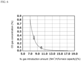
- FIG.6 is a graph showing a correlation between the amount of the N 2 gas introduced into the furnace and the CO gas concentration in the furnace.
- plotting was omitted with regard to examples in which the N 2 gas was introduced in amounts of smaller than 7%; incommensurably higher CO gas concentrations (e.g., 8% or higher) were observed when the N 2 gas was introduced in amounts of smaller than 7% as compared to when it was introduced in amounts of 7% or larger.
- the CO gas concentration was about 0.8% when the N 2 gas introduction amount was 7%; a sufficient decrease in CO gas concentration was confirmed. Further, as a result of increasing the N 2 gas introduction amount to 10% for the purpose of completely restricting the combustion and consumption of coke, while the N 2 gas introduction amount increased by 25% as compared to when the N 2 gas introduction amount was 8%, the CO gas concentration dropped to about 0.1% which was an 80% decrease, indicating that the combustion and consumption of coke was able to be restricted sufficiently.
- a melt discharging property at the time of starting up the blast furnace was ensured, whereby the blast furnace was able to resume its process operations in 21 days after restart without having to remove in-furnace residues.
Landscapes
- Engineering & Computer Science (AREA)
- Chemical & Material Sciences (AREA)
- Manufacturing & Machinery (AREA)
- Materials Engineering (AREA)
- Metallurgy (AREA)
- Organic Chemistry (AREA)
- Manufacture Of Iron (AREA)
Abstract
a combustion step of combusting coke remaining in the furnace by blowing an oxygen-containing gas into the furnace from a burner inserted into a tap hole after blasting is stopped, and thereby reducing the volume of in-furnace residues;
a charging step of newly charging coke into a volume-reduced area formed in the combustion step; and
a blasting step of restarting blasting from a tuyere,
wherein an introduction step of introducing an inert gas into the furnace is provided during a period from after stopping blasting to before performing the blasting step.
Description
- The present invention relates to a blast-furnace operation method for restarting blasting after the blasting of a blast furnace is stopped upon operation shutdown; and a blast furnace used in such blast-furnace operation method.
- Conventionally, blast furnace operation is carried out on the premises that the operation is never stopped after blowing-in except for short-period shutdowns involving scheduled equipment repair, and that the operation itself shall continue though there may be made operational adjustments such as reducing production volume. This is because there is no economic rationality as the restart cost incurred by operation shutdown is enormous, and there is no upward elasticity in terms of production volume as a period of about half a year is required before restart once the operation is shutdown.
- In the meantime, unlike up until now where steel demand has been consistently high globally and there has been an underlying increase in its production, steel demand can now change significantly in a short period of time due to the current unstable world economic situation. In this regard, flexibility to significant changes in production volume is now also required for blast furnace operation, and banking, a process to stop the blast furnace and put it into such a state where the operation can be resumed, has become increasingly important.
- A shutdown involving the refurbishment of a blast furnace takes place on the premise that the shutdown lasts for a certain period of time; it is therefore common that the furnace bottom part be disassembled to remove the coke, molten pig iron, and molten slag that have accumulated therein. Meanwhile, in banking that assumes a flexible restart depending on the economic situation, it is desired that such operation is not conducted as it will lead to a prolonged shutdown period. However, if not removing in-furnace residues, the coke remaining in the furnace will be combusted and consumed to form smaller diameters, whereby there will be observed a deteriorated discharging property of the molten pig iron and molten slag at the time of restart due to a decrease in porosity. Further, the molten pig iron and molten slag that have remained due to a decrease in furnace heat already have a deteriorated fluidity; therefore, if restarting the blast-furnace operation without carrying out the discharge operation, there is a high risk that a discharge failure of the molten pig iron and molten slag may occur, and restart may even become impossible in the worst-case scenario.
- With regard to the abovementioned problems, Patent Literature 1, for example, addresses restriction of deterioration in discharging property at the time of restart by using incombustibles with low-melting point compositions as incombustibles that are to be put into the furnace for the purpose of avoiding troubles in the maintenance and repair operation. Further, in Patent Literature 2, it was found that not only the smaller diameters of the remaining coke that were formed by the combustion and consumption thereof, but the pig iron, slag and the like adhering to such coke also contributed to the increase in the amount of melt as they again melted at the time of restart. As a result, in Patent Literature 2, the increase in the amount of melt at the time of restart is prevented by charging new coke after purposefully combusting and eliminating the aforementioned coke using a burner.
-
- Patent Literature 1:
JP-A-2005-248293 - Patent Literature 2:
Japanese Patent No.6947345 - However, in the case of Patent Literature 1, there is still a problem in that the low-melting point incombustibles are in fact added from outside the system in addition to the in-furnace slag generated upon operation restart, which results in a larger amount of the molten slag that has to be discharged. Further, as compared to the conventional technique, Patent Literature 2 is advanced in that the increase in the amount of melt is restricted; however, the newly charged coke itself cannot be prevented from forming smaller diameters when combusted, which leads to a problem that the longer the banking lasts, the smaller the diameters of the coke will be when combusted and consumed, and the less likely that the deterioration in discharging property caused thereby is avoided.
- It is an object of the present invention to provide a blast-furnace operation method and blast furnace capable of realizing a smooth restart of a blast furnace by avoiding deterioration in melt discharging property as a result of restricting coke from forming smaller diameters due to combustion and consumption, which was not achievable by prior patents.
- The blast-furnace operation method of the present invention was developed to solve the above problems. Specifically, the method of the invention is a blast-furnace operation method for restarting blasting after the blasting of a blast furnace is stopped upon operation shutdown, and this method includes:
- a combustion step of combusting coke remaining in the furnace by blowing an oxygen-containing gas into the furnace from a burner inserted into a tap hole after blasting is stopped, and thereby reducing the volume of in-furnace residues;
- a charging step of newly charging coke into a volume-reduced area formed in the combustion step; and
- a blasting step of restarting blasting from a tuyere,
- Here, with regard to the blast-furnace operation method of the present invention that is configured as above, it is considered that more preferable solutions can be brought when:
- (1) a determination step of determining whether or not coke combustion in the blast furnace is continuing is further provided after the introduction step;
- (2) in the determination step, gas concentration in the blast furnace is analyzed, and it is determined that coke combustion in the blast furnace is continuing when a CO gas concentration is as high as or higher than a threshold value;
- (3) if it is determined in the determination step that coke combustion in the blast furnace is continuing, there is further performed an additional step of charging additional coke into the furnace up to an upper region of the tuyere;
- (4) in the introduction step, the inert gas is introduced into the blast furnace in an amount of not smaller than 7% and not larger than 13% per hour with respect to the capacity of the blast furnace; and
- (5) in the introduction step, the inert gas is introduced into the blast furnace from an introduction port formed above the tuyere of the blast furnace.
- Further, the blast furnace of the present invention is a blast furnace configured to perform the abovementioned blast-furnace operation method, and includes an introduction port that is configured to introduce an inert gas and is formed above a tuyere.
- With the blast-furnace operation method of the present invention, by introducing an inert gas into the blast furnace, coke in the blast furnace can be restricted from forming smaller diameters, which is caused by the combustion and consumption of the coke. In this way, the restart of a blast furnace can be performed smoothly as deterioration in melt discharging property is prevented. Further, with the present invention, since there is no need to keep the pressure inside the furnace positive, there is no risk that the in-furnace gas may leak out of the furnace as a result of introducing an inert gas, thereby allowing various operations to be carried out in parallel at the periphery of the blast furnace.
-
- [
FIG.1 ] is a cross-sectional schematic diagram showing part of a furnace body cross-sectional surface of a blast furnace. - [
FIG.2 ] is a cross-sectional schematic diagram showing the furnace lower part of the blast furnace of a state where a burner has been inserted from a tap hole. - [
FIG.3 ] is a set of schematic diagrams showing one example of the burner. - [
FIG.4 ] is a cross-sectional schematic diagram showing a state where the volume of in-furnace residues has been reduced by burning the remaining coke with the burner. - [
FIG.5 ] is a schematic diagram illustrating one embodiment of the furnace body of the blast furnace configured to perform the blast-furnace operation method of the present invention. - [
FIG.6 ] is a graph showing a correlation between the amount of a N2 gas introduced into the furnace and a CO gas concentration in the furnace. Description of Embodiments - An embodiment of the present invention is described in detail hereunder. Here, the following embodiment is a set of examples of a device and/or method embodying the technical concept of the present invention and is not to limit the configuration of the present invention to those shown below. That is, various modifications can be made to the technical concept of the present invention within the technical scope described in the claims.
-
FIG.1 is a cross-sectional schematic diagram showing part of a furnace body cross-sectional surface of a blast furnace. In the embodiment shown inFIG. 1 , when stopping the blasting of the blast furnace for a long period of time, blasting is stopped in such a way that the height of a raw material-filled layer surface that is immediately above the tuyere(s) of the blast furnace is lowered so as to be positioned lower than the upper end of the bosh zone of the blast furnace. Later, when the blast furnace is put back into normal operation by restarting blasting from the tuyere, a burner is at first inserted into the furnace from the tap hole, whereby an oxygen-containing gas is or both an oxygen-containing gas and a combustible gas are blown into the furnace from the burner so as to combust the coke remaining in the furnace and thus reduce the volume of in-furnace residues (combustion step). -
FIG.2 is a cross-sectional schematic diagram showing the furnace lower part of the blast furnace of a state where the burner has been inserted from the tap hole. In the embodiment shown inFIG.2 , since the tap hole is blocked by a material called mud material when the blasting of the blast furnace is stopped, the tap hole blocked by the mud material has to be opened at first so as to allow the burner to be inserted into the furnace. The opening of the tap hole can be performed by a known tap hole opener. The burner can be inserted into the furnace lower part of the blast furnace from the tap hole after the tap hole is opened. -
FIGs.3(a) and (b) are both schematic diagrams showing one example of the burner. In the embodiments shown inFIGs.3(a) and (b) , the burner has a double-pipe structure composed of an inner pipe and outer pipe through which a gas flows. The burner also has a cap that covers the end portions of the inner and outer pipes; and a thermocouple that is provided outside the outer pipe and is used to measure the temperature of the burner. When a cap is provided as is the case shown inFIG.3(a) , a gas blown into the burner from a gas introduction inlet of the inner pipe can be discharged from a gas discharge outlet of the outer pipe without leaking outside. Meanwhile, when there is provided no cap as is the case shown inFIG.3(b) , the gas blown into the burner from the gas introduction inlet of the inner pipe will be supplied into the furnace. Thus, the burner has a function of being cooled by flowing a gas from the inner pipe to the outer pipe with a cap being present, whereby the burner can be stably inserted into the furnace. - Further, at the start of combustion, cooling by the gas flow from the inner pipe to the outer pipe is stopped, whereby the cap is melted and removed by furnace heat or the like so as to allow, for example, a combustible gas to be blown into the furnace from the inner pipe of the burner and an oxygen-containing gas as a combustion-supporting gas to be blown into the furnace lower part from the outer pipe of the burner. When the temperature of the burner tip portion has exceeded the combustion start temperature (approximately 800°C) of the coke that is present therearound, the coke will be burnt by switching the gas blown from the burner to the oxygen-containing gas only. As the oxygen-containing gas, it is preferred that pure oxygen is blown; however, there may also be used a gas whose oxygen concentration is lower than 100% so long as coke combustion can be sustained. Here, in this embodiment, there is shown an example where a combustible gas and an oxygen-containing gas are blown from the burner; however, other than such example, there may also be employed a configuration where only an oxygen-containing gas is blown from the burner.
-
FIG.4 is a cross-sectional schematic diagram showing a state where the volume of in-furnace residues has been reduced by burning the remaining coke with the burner. In the embodiment shown inFIG.4 , when coke has disappeared by combustion, more coke will roll into the space from which the aforesaid coke has disappeared by combustion depending on a repose angle, thereby causing coke to successively disappear by combustion, thus reducing the volume of in-furnace residues. - Later, oxygen blowing from the burner is stopped, and unused coke is then charged and loaded from the upper part of the blast furnace into a volume-reduced area which is a space formed inside the furnace as a result of reducing the volume of in-furnace residues (charging step). Next, oxygen is again blown from the burner to heat the newly loaded coke, and when the temperature of the coke at the tuyere tip portion has exceeded, for example, 2,000°C, a hot air of, for example, 1,100°C will be blasted from the tuyere (blasting step), whereby the blast furnace is started up by switching to heating from the tuyere.
- The blast-furnace operation method and blast furnace of the present invention are characterized in that there is provided an introduction step of introducing an inert gas into the blast furnace during a period from after stopping blasting to before performing the blasting step. Here, the "period from after stopping blasting to before performing the blasting step" includes any time point selected from (1) a time point after stopping blasting and before performing the combustion step; (2) a time point after performing the combustion step and before performing the charging step; and (3) a time point after performing the charging step and before performing the blasting step. Of them, the time point (2) is preferred. If introducing an inert gas at the time point (1), process delay will occur as coke combustion may be thwarted. If introducing an inert gas at the time point (3), part of the unused coke charged in the charging step will react due to a temperature rise in the furnace at the time point (2), thereby diminishing the effect of the present invention.
- In the blast-furnace operation method of the present invention, an inert gas is introduced into the blast furnace in the introduction step, thereby restricting contact between air and the coke charged in the volume-reduced area that is present between the tuyere and the tap hole, thus restricting coke combustion. Here, as the inert gas, there may be used various types of inert gases such as argon and nitrogen; nitrogen (N2) is most suitable in terms of cost.
-
FIG.5 is a schematic diagram illustrating one embodiment of the furnace body of the blast furnace configured to perform the blast-furnace operation method of the present invention. As shown inFIG.5 , the blast furnace is configured in such a manner that a pipe serving as an introduction port is provided above the tuyere, and an inert gas is introduced into the blast furnace from such introduction port. Here, in the example shown inFIG.5 , although the introduction port is provided immediately above the tuyere, the introduction port may also be provided in the vicinity of the furnace top of the blast furnace (e.g., a location that is about 5 m below the furnace top of the blast furnace, provided that the height of the blast furnace is 100 m). By providing the introduction port above the tuyere, hindrance to inert gas introduction that is caused by the coke charged in the volume-reduced area between the tuyere and the tap hole can be restricted. Further, since the introduction port for introducing an inert gas is provided separately from other openings such as a raw material charging port, the tuyere, and the tap hole, the inert gas introduction operation can be performed without interfering with other operations and equipment as compared to a configuration where the inert gas is introduced from other openings. - Here, the amount of the inert gas introduced into the blast furnace is determined by the capacity of the blast furnace. Specifically, it is preferred that the inert gas be introduced in an amount of not smaller than 7% and not larger than 13% per hour with respect to the capacity of the blast furnace. The reason that this range is preferable is because if the amount introduced is smaller than 7%, it is difficult to restrict coke combustion due to the excessively small amount, and the combustion restriction effect will remain the same even when the amount introduced is larger than 13%.
- Here, in the blast-furnace operation method of the present invention, it is preferred that there is added a determination step of determining whether or not coke combustion is still continuing in the blast furnace, after the introduction step of introducing an inert gas into the blast furnace. Specifically, a gas analyzer is installed in a recovery pipe (not shown) for collecting the gas discharged from the furnace top, and this gas analyzer is used to analyze the gas concentration in the furnace (concentration of gas discharged from the furnace top). Further, when the concentration of the CO gas is high (as high as or higher than a threshold value), it will be determined that coke combustion is continuing, and when the concentration of the CO gas is low (lower than the threshold value), it will be determined that coke combustion is not continuing. The threshold value of the CO gas concentration may, for example, be 1%.
- Moreover, in the determination step, when it is determined that coke combustion is still continuing, it is preferred that additional coke be charged into the furnace up to an upper region of the tuyere, whereby the oxygen remaining in the furnace and the coke above the tuyere that has been added can be reacted with each other (combusted). In this way, the combustion and consumption of the coke that is present between the tuyere and the tap hole can be restricted so that the coke between the tuyere and the tap hole can be prevented from forming smaller diameters and contributing to a poor discharging property caused thereby.
- According to the abovementioned embodiment, in fact, a blast furnace having an inner capacity of 5,000 m3 was used, various amounts of N2 gas were introduced into the furnace, and changes in the CO gas concentration in the furnace were calculated.
FIG.6 is a graph showing a correlation between the amount of the N2 gas introduced into the furnace and the CO gas concentration in the furnace. Here, in the graph shown inFIG.6 , plotting was omitted with regard to examples in which the N2 gas was introduced in amounts of smaller than 7%; incommensurably higher CO gas concentrations (e.g., 8% or higher) were observed when the N2 gas was introduced in amounts of smaller than 7% as compared to when it was introduced in amounts of 7% or larger. In the examples, the CO gas concentration was about 0.8% when the N2 gas introduction amount was 7%; a sufficient decrease in CO gas concentration was confirmed. Further, as a result of increasing the N2 gas introduction amount to 10% for the purpose of completely restricting the combustion and consumption of coke, while the N2 gas introduction amount increased by 25% as compared to when the N2 gas introduction amount was 8%, the CO gas concentration dropped to about 0.1% which was an 80% decrease, indicating that the combustion and consumption of coke was able to be restricted sufficiently. By using the present invention, a melt discharging property at the time of starting up the blast furnace was ensured, whereby the blast furnace was able to resume its process operations in 21 days after restart without having to remove in-furnace residues.
Claims (7)
- A blast-furnace operation method for restarting blasting after the blasting of a blast furnace is stopped upon operation shutdown, comprising:a combustion step of combusting coke remaining in the furnace by blowing an oxygen-containing gas into the furnace from a burner inserted into a tap hole after blasting is stopped, and thereby reducing the volume of in-furnace residues;a charging step of newly charging coke into a volume-reduced area formed in the combustion step; anda blasting step of restarting blasting from a tuyere,wherein an introduction step of introducing an inert gas into the furnace is provided during a period from after stopping blasting to before performing the blasting step.
- The blast-furnace operation method according to claim 1, wherein a determination step of determining whether or not coke combustion in the blast furnace is continuing is further provided after the introduction step.
- The blast-furnace operation method according to claim 2, wherein in the determination step, gas concentration in the blast furnace is analyzed, and it is determined that coke combustion in the blast furnace is continuing when a CO gas concentration is as high as or higher than a threshold value.
- The blast-furnace operation method according to claim 2 or 3, wherein when it is determined in the determination step that coke combustion in the blast furnace is continuing, there is further performed an additional step of charging additional coke into the furnace up to an upper region of the tuyere.
- The blast-furnace operation method according to claim 1, wherein in the introduction step, the inert gas is introduced into the blast furnace in an amount of not smaller than 7% and not larger than 13% per hour with respect to the capacity of the blast furnace.
- The blast-furnace operation method according to claim 1, wherein in the introduction step, the inert gas is introduced into the blast furnace from an introduction port formed above the tuyere of the blast furnace.
- A blast furnace configured to perform the blast-furnace operation method according to claim 1, comprising an introduction port that is configured to introduce an inert gas and is formed above a tuyere.
Applications Claiming Priority (2)
| Application Number | Priority Date | Filing Date | Title |
|---|---|---|---|
| JP2022088244 | 2022-05-31 | ||
| PCT/JP2023/017685 WO2023233957A1 (en) | 2022-05-31 | 2023-05-11 | Blast-furnace operation method and blast furnace |
Publications (2)
| Publication Number | Publication Date |
|---|---|
| EP4495270A1 true EP4495270A1 (en) | 2025-01-22 |
| EP4495270A4 EP4495270A4 (en) | 2025-06-18 |
Family
ID=89026357
Family Applications (1)
| Application Number | Title | Priority Date | Filing Date |
|---|---|---|---|
| EP23815717.6A Pending EP4495270A4 (en) | 2022-05-31 | 2023-05-11 | BLAST FURNACE AND BLAST FURNACE OPERATING METHOD |
Country Status (4)
| Country | Link |
|---|---|
| EP (1) | EP4495270A4 (en) |
| JP (1) | JP7626237B2 (en) |
| CN (1) | CN119137293A (en) |
| WO (1) | WO2023233957A1 (en) |
Family Cites Families (6)
| Publication number | Priority date | Publication date | Assignee | Title |
|---|---|---|---|---|
| JPS5271307A (en) * | 1975-12-11 | 1977-06-14 | Nippon Steel Corp | Shutdown of blast furnace |
| JPS5935962B2 (en) * | 1977-05-10 | 1984-08-31 | 新日本製鐵株式会社 | How to reheat a dormant blast furnace |
| JP4100361B2 (en) | 2004-03-08 | 2008-06-11 | 住友金属工業株式会社 | Reduced blast furnace operation method |
| JP5835076B2 (en) * | 2012-04-17 | 2015-12-24 | 新日鐵住金株式会社 | Heating method of charge and residue at bottom of blast furnace |
| EP4151753A4 (en) | 2020-05-15 | 2023-11-01 | JFE Steel Corporation | METHOD OF USING BLAST FURNACE |
| WO2021230027A1 (en) * | 2020-05-15 | 2021-11-18 | Jfeスチール株式会社 | Blast furnace operation method |
-
2023
- 2023-05-11 WO PCT/JP2023/017685 patent/WO2023233957A1/en not_active Ceased
- 2023-05-11 CN CN202380039892.3A patent/CN119137293A/en active Pending
- 2023-05-11 EP EP23815717.6A patent/EP4495270A4/en active Pending
- 2023-05-11 JP JP2023549669A patent/JP7626237B2/en active Active
Also Published As
| Publication number | Publication date |
|---|---|
| EP4495270A4 (en) | 2025-06-18 |
| JP7626237B2 (en) | 2025-02-04 |
| WO2023233957A1 (en) | 2023-12-07 |
| CN119137293A (en) | 2024-12-13 |
| JPWO2023233957A1 (en) | 2023-12-07 |
Similar Documents
| Publication | Publication Date | Title |
|---|---|---|
| US12378615B2 (en) | Blast furnace operation method | |
| JP7306421B2 (en) | How to start up a blast furnace | |
| TW202208637A (en) | blast furnace operation method | |
| US20140318319A1 (en) | Starting a smelting process | |
| JP7626237B2 (en) | Blast furnace operation method and blast furnace | |
| US10781497B2 (en) | Method of sealing and repairing a refractory tap hole | |
| RU2812287C1 (en) | Way blast furnace works | |
| US3819164A (en) | Operation of a blast furnace | |
| JP2009041043A (en) | Method for suppressing slag-forming in continuous melting furnace | |
| JP7683642B2 (en) | Blast furnace operation method | |
| JP7666416B2 (en) | Blast furnace operation method | |
| TW202424210A (en) | Blast furnace operation method | |
| JPS5935962B2 (en) | How to reheat a dormant blast furnace | |
| KR100758436B1 (en) | Prevention method of attachment of converter cone part now | |
| JP7193032B1 (en) | Supplied heat amount estimation method, supplied heat amount estimation device, and blast furnace operation method | |
| JP7196967B1 (en) | Method for estimating deposit shape of filler in blast furnace and method for replacing coke in blast furnace | |
| JP7661949B2 (en) | Blast furnace operation method | |
| CN120488735A (en) | Method for prolonging damping-down time of smelting reduction furnace | |
| JP2023152640A (en) | Blast furnace operation method | |
| BR112022021841B1 (en) | BLAST FURNACE OPERATION METHOD | |
| JPH08260010A (en) | Operation method for large amount of pulverized coal injection in blast furnace | |
| JPH07268416A (en) | Blast furnace operation method | |
| JP2024013311A (en) | Blast furnace operating method | |
| CN116855649A (en) | A method for quickly starting up an ironmaking blast furnace and reaching production | |
| JP2022152721A (en) | Operation method of blast furnace |
Legal Events
| Date | Code | Title | Description |
|---|---|---|---|
| STAA | Information on the status of an ep patent application or granted ep patent |
Free format text: STATUS: THE INTERNATIONAL PUBLICATION HAS BEEN MADE |
|
| PUAI | Public reference made under article 153(3) epc to a published international application that has entered the european phase |
Free format text: ORIGINAL CODE: 0009012 |
|
| STAA | Information on the status of an ep patent application or granted ep patent |
Free format text: STATUS: REQUEST FOR EXAMINATION WAS MADE |
|
| 17P | Request for examination filed |
Effective date: 20241018 |
|
| AK | Designated contracting states |
Kind code of ref document: A1 Designated state(s): AL AT BE BG CH CY CZ DE DK EE ES FI FR GB GR HR HU IE IS IT LI LT LU LV MC ME MK MT NL NO PL PT RO RS SE SI SK SM TR |
|
| A4 | Supplementary search report drawn up and despatched |
Effective date: 20250520 |
|
| RIC1 | Information provided on ipc code assigned before grant |
Ipc: C21B 7/24 20060101ALI20250514BHEP Ipc: C21B 7/00 20060101ALI20250514BHEP Ipc: C21B 5/00 20060101AFI20250514BHEP |
|
| DAV | Request for validation of the european patent (deleted) | ||
| DAX | Request for extension of the european patent (deleted) |