EP4495058A1 - System for controlling ammonia reactor and method of generating hydrogen - Google Patents
System for controlling ammonia reactor and method of generating hydrogen Download PDFInfo
- Publication number
- EP4495058A1 EP4495058A1 EP24187550.9A EP24187550A EP4495058A1 EP 4495058 A1 EP4495058 A1 EP 4495058A1 EP 24187550 A EP24187550 A EP 24187550A EP 4495058 A1 EP4495058 A1 EP 4495058A1
- Authority
- EP
- European Patent Office
- Prior art keywords
- ammonia
- cracker
- supply amount
- controller
- temperature
- Prior art date
- Legal status (The legal status is an assumption and is not a legal conclusion. Google has not performed a legal analysis and makes no representation as to the accuracy of the status listed.)
- Pending
Links
Images


Classifications
-
- C—CHEMISTRY; METALLURGY
- C01—INORGANIC CHEMISTRY
- C01B—NON-METALLIC ELEMENTS; COMPOUNDS THEREOF; METALLOIDS OR COMPOUNDS THEREOF NOT COVERED BY SUBCLASS C01C
- C01B3/00—Hydrogen; Gaseous mixtures containing hydrogen; Separation of hydrogen from mixtures containing it; Purification of hydrogen; Reversible storage of hydrogen
- C01B3/02—Production of hydrogen; Production of gaseous mixtures containing hydrogen
- C01B3/04—Production of hydrogen; Production of gaseous mixtures containing hydrogen by decomposition of inorganic compounds
- C01B3/047—Decomposition of ammonia
-
- B—PERFORMING OPERATIONS; TRANSPORTING
- B01—PHYSICAL OR CHEMICAL PROCESSES OR APPARATUS IN GENERAL
- B01J—CHEMICAL OR PHYSICAL PROCESSES, e.g. CATALYSIS OR COLLOID CHEMISTRY; THEIR RELEVANT APPARATUS
- B01J19/00—Chemical, physical or physico-chemical processes in general; Their relevant apparatus
- B01J19/0006—Controlling or regulating processes
- B01J19/0013—Controlling the temperature of the process
-
- G—PHYSICS
- G05—CONTROLLING; REGULATING
- G05D—SYSTEMS FOR CONTROLLING OR REGULATING NON-ELECTRIC VARIABLES
- G05D23/00—Control of temperature
- G05D23/19—Control of temperature characterised by the use of electric means
- G05D23/30—Automatic controllers with an auxiliary heating device affecting the sensing element, e.g. for anticipating change of temperature
-
- H—ELECTRICITY
- H01—ELECTRIC ELEMENTS
- H01M—PROCESSES OR MEANS, e.g. BATTERIES, FOR THE DIRECT CONVERSION OF CHEMICAL ENERGY INTO ELECTRICAL ENERGY
- H01M8/00—Fuel cells; Manufacture thereof
- H01M8/04—Auxiliary arrangements, e.g. for control of pressure or for circulation of fluids
- H01M8/04298—Processes for controlling fuel cells or fuel cell systems
- H01M8/04313—Processes for controlling fuel cells or fuel cell systems characterised by the detection or assessment of variables; characterised by the detection or assessment of failure or abnormal function
- H01M8/0432—Temperature; Ambient temperature
- H01M8/04373—Temperature; Ambient temperature of auxiliary devices, e.g. reformers, compressors, burners
-
- H—ELECTRICITY
- H01—ELECTRIC ELEMENTS
- H01M—PROCESSES OR MEANS, e.g. BATTERIES, FOR THE DIRECT CONVERSION OF CHEMICAL ENERGY INTO ELECTRICAL ENERGY
- H01M8/00—Fuel cells; Manufacture thereof
- H01M8/04—Auxiliary arrangements, e.g. for control of pressure or for circulation of fluids
- H01M8/04298—Processes for controlling fuel cells or fuel cell systems
- H01M8/04694—Processes for controlling fuel cells or fuel cell systems characterised by variables to be controlled
- H01M8/04858—Electric variables
- H01M8/04925—Power, energy, capacity or load
-
- H—ELECTRICITY
- H01—ELECTRIC ELEMENTS
- H01M—PROCESSES OR MEANS, e.g. BATTERIES, FOR THE DIRECT CONVERSION OF CHEMICAL ENERGY INTO ELECTRICAL ENERGY
- H01M8/00—Fuel cells; Manufacture thereof
- H01M8/06—Combination of fuel cells with means for production of reactants or for treatment of residues
- H01M8/0606—Combination of fuel cells with means for production of reactants or for treatment of residues with means for production of gaseous reactants
-
- H—ELECTRICITY
- H01—ELECTRIC ELEMENTS
- H01M—PROCESSES OR MEANS, e.g. BATTERIES, FOR THE DIRECT CONVERSION OF CHEMICAL ENERGY INTO ELECTRICAL ENERGY
- H01M8/00—Fuel cells; Manufacture thereof
- H01M8/06—Combination of fuel cells with means for production of reactants or for treatment of residues
- H01M8/0662—Treatment of gaseous reactants or gaseous residues, e.g. cleaning
-
- B—PERFORMING OPERATIONS; TRANSPORTING
- B01—PHYSICAL OR CHEMICAL PROCESSES OR APPARATUS IN GENERAL
- B01J—CHEMICAL OR PHYSICAL PROCESSES, e.g. CATALYSIS OR COLLOID CHEMISTRY; THEIR RELEVANT APPARATUS
- B01J2219/00—Chemical, physical or physico-chemical processes in general; Their relevant apparatus
- B01J2219/00049—Controlling or regulating processes
- B01J2219/00051—Controlling the temperature
- B01J2219/00054—Controlling or regulating the heat exchange system
- B01J2219/00056—Controlling or regulating the heat exchange system involving measured parameters
- B01J2219/00058—Temperature measurement
- B01J2219/00063—Temperature measurement of the reactants
-
- B—PERFORMING OPERATIONS; TRANSPORTING
- B01—PHYSICAL OR CHEMICAL PROCESSES OR APPARATUS IN GENERAL
- B01J—CHEMICAL OR PHYSICAL PROCESSES, e.g. CATALYSIS OR COLLOID CHEMISTRY; THEIR RELEVANT APPARATUS
- B01J2219/00—Chemical, physical or physico-chemical processes in general; Their relevant apparatus
- B01J2219/00049—Controlling or regulating processes
- B01J2219/00051—Controlling the temperature
- B01J2219/00074—Controlling the temperature by indirect heating or cooling employing heat exchange fluids
- B01J2219/00087—Controlling the temperature by indirect heating or cooling employing heat exchange fluids with heat exchange elements outside the reactor
-
- B—PERFORMING OPERATIONS; TRANSPORTING
- B01—PHYSICAL OR CHEMICAL PROCESSES OR APPARATUS IN GENERAL
- B01J—CHEMICAL OR PHYSICAL PROCESSES, e.g. CATALYSIS OR COLLOID CHEMISTRY; THEIR RELEVANT APPARATUS
- B01J2219/00—Chemical, physical or physico-chemical processes in general; Their relevant apparatus
- B01J2219/00049—Controlling or regulating processes
- B01J2219/00191—Control algorithm
- B01J2219/00193—Sensing a parameter
- B01J2219/00195—Sensing a parameter of the reaction system
- B01J2219/002—Sensing a parameter of the reaction system inside the reactor
-
- Y—GENERAL TAGGING OF NEW TECHNOLOGICAL DEVELOPMENTS; GENERAL TAGGING OF CROSS-SECTIONAL TECHNOLOGIES SPANNING OVER SEVERAL SECTIONS OF THE IPC; TECHNICAL SUBJECTS COVERED BY FORMER USPC CROSS-REFERENCE ART COLLECTIONS [XRACs] AND DIGESTS
- Y02—TECHNOLOGIES OR APPLICATIONS FOR MITIGATION OR ADAPTATION AGAINST CLIMATE CHANGE
- Y02E—REDUCTION OF GREENHOUSE GAS [GHG] EMISSIONS, RELATED TO ENERGY GENERATION, TRANSMISSION OR DISTRIBUTION
- Y02E60/00—Enabling technologies; Technologies with a potential or indirect contribution to GHG emissions mitigation
- Y02E60/30—Hydrogen technology
- Y02E60/36—Hydrogen production from non-carbon containing sources, e.g. by water electrolysis
-
- Y—GENERAL TAGGING OF NEW TECHNOLOGICAL DEVELOPMENTS; GENERAL TAGGING OF CROSS-SECTIONAL TECHNOLOGIES SPANNING OVER SEVERAL SECTIONS OF THE IPC; TECHNICAL SUBJECTS COVERED BY FORMER USPC CROSS-REFERENCE ART COLLECTIONS [XRACs] AND DIGESTS
- Y02—TECHNOLOGIES OR APPLICATIONS FOR MITIGATION OR ADAPTATION AGAINST CLIMATE CHANGE
- Y02E—REDUCTION OF GREENHOUSE GAS [GHG] EMISSIONS, RELATED TO ENERGY GENERATION, TRANSMISSION OR DISTRIBUTION
- Y02E60/00—Enabling technologies; Technologies with a potential or indirect contribution to GHG emissions mitigation
- Y02E60/30—Hydrogen technology
- Y02E60/50—Fuel cells
Definitions
- Embodiments of the present disclosure relate generally to a system and method for controlling an ammonia reactor and generating hydrogen.
- the ammonia decomposition amount may variably depend on the state of a driving vehicle that may employ, e.g., a fuel cell, and the ammonia supply amount may be changed depending on the ammonia cracker temperature also referred to as the ammonia reactor) so that an ammonia decomposition ratio in the reactor due to a change in the reactor temperature can be stabilized.
- the ammonia decomposition ratio may be decreased, which may cause a catalyst deactivation within an inside of the reactor or performance degradation of an entire apparatus. Accordingly, an amount of residual ammonia in the apparatus may be increased.
- the residual ammonia may be supplied to an adsorption tower or a fuel cell, thereby causing overall performance degradation or unexpected defects of the apparatus.
- a system for controlling an ammonia reactor having improved process efficiency.
- a system for controlling an ammonia reactor includes a sensor configured to measure an internal temperature of a cracker, a controller configured to receive temperature information collected from the sensor, a hydrogen supplier configured to determine a hydrogen supply amount into the cracker according to a first signal from the controller, and an ammonia supplier configured to determine an ammonia supply amount into the cracker according to a second signal from the controller.
- the controller is configured to receive ammonia supply amount information from the ammonia supplier, and to determine the first signal based on the temperature information and the ammonia supply amount information.
- the system may further include a storage device configured to store a preset heat supply amount information to a fuel cell through the cracker.
- the controller may be configured to check the preset heat supply amount information from the storage device, and to calculate an internal heat absorption information of the cracker based on the temperature information.
- the controller may be configured to compare the preset heat supply amount information with the internal heat absorption information of the cracker, and to temporarily lower a power of the fuel cell.
- the reactor may further include a temperature sensor configured to detect a temperature of ammonia supplied into the cracker from the ammonia supplier, and a pre-heater for pre-heating ammonia supplied into the cracker according to a third signal from the controller.
- the controller may be configured to receive an ammonia temperature information in the ammonia supplier from the temperature sensor, and to determine the third signal for operating the pre-heater based on the ammonia temperature information.
- the controller may be configured to receive a hydrogen supply amount information from the hydrogen supplier, and to determine the second signal based on the temperature information and the hydrogen supply amount information.
- the controller may be configured to determine the ammonia supply amount as a first capacity according to the second signal if a temperature of the cracker corresponds to a preset first temperature range, and to determine the ammonia supply amount as a second capacity according to the second signal if the temperature of the cracker corresponds to a preset second temperature range.
- a lower limit of the first temperature range may be greater than an upper limit of the second temperature range, and the first capacity may be less than the second capacity.
- the senor may be configured to measure temperatures of internal portions of the cracker including a first portion and a second portion of the cracker.
- the ammonia supplier may be connected to the first portion and the second portion.
- the controller may be configured to determine the second signal based on temperature information of the first portion and the second portion.
- the controller may be configured to determine the first signal or the second signal based on the temperature information, the ammonia supply amount information and the hydrogen supply amount information.
- ammonia is fed to a cracker.
- Temperature information collected from a sensor that measures an internal temperature of the cracker is received.
- Ammonia supply amount information is received from an ammonia supplier that determines an ammonia supply amount into the cracker.
- a hydrogen supply amount information is received from a hydrogen supplier that determines a hydrogen supply amount into the cracker.
- a first signal or a second signal is provided to the hydrogen supplier or the ammonia supplier based on the temperature information, the ammonia supply amount information and the hydrogen supply amount information.
- the ammonia reactor control system may be configured to increase or decrease a supply amount of ammonia and/or an unreacted hydrogen depending on a temperature of a cracker to maintain a proper internal temperature of the cracker. Accordingly, a reduction of a reaction rate in the cracker may be prevented.
- the ammonia reactor control system may appropriately be configured to maintain an internal temperature in the cracker to reduce an amount of a residual ammonia. Accordingly, performance deterioration of the system due to the residual ammonia may be prevented.
- an element or portion when an element or portion is recited as being "connected" to another element or portion, the recitation includes a direct connection, and an indirect connection, and an indirect connection may include a wireless communication network.
- a reference numeral designating an operation is used for convenience of descriptions and is not intended to limit the order of the operation, and the operation may be performed differently from the specified order unless a specific order is clearly described herein.
- the device includes all various devices capable of performing arithmetic processing and providing a result to a user.
- the device according to the present disclosure may include all of a computer, a server device and a portable terminal, or may include any one of the forms.
- the computer may include, e.g., a notebook computer, a desktop, a laptop computer, a tablet PC, a slate PC, etc., equipped with a web browser.
- the server device is a server that processes information by communicating with an external device, and may include an application server, a computing server, a database server, a file server, a game server, a mail server, a proxy server, a web server, etc.
- the portable terminal may be a wireless communication device having portability and mobility.
- the portable terminal may include all types of handheld-based wireless communication devices such as a personal communication system (PCS), a global system for mobile communications (GSM), a personal digital cell (PDC), a personal handy phone system (PHS), a personal digital assistant (PDA), an International Mobile Telecommunication (IMT)-2000, Code Division Multiple Access (CDMA)-2000, W-CDMA (W-Code Division Multiple Access), a wireless broadband Internet (WiBro) terminal, a smartphone, etc., and may include wearable devices such as a watch, a ring, a bracelet, an anklet, a necklace, glasses, contact lenses, or a head-mounted-device (HMD).
- PCS personal communication system
- GSM global system for mobile communications
- PDC personal digital cell
- PHS personal handy phone system
- IMT International Mobile Telecommunication
- CDMA Code Division Multiple Access
- W-CDMA W-Code Division Multiple Access
- WiBro wireless broadband Internet
- FIG. 1 is a block diagram of a system for controlling an ammonia reactor in accordance with embodiments of the present disclosure.
- a system for controlling an ammonia reactor system 10 (hereinafter, referred to as the ammonia reactor control system) includes a cracker 100, an absorber 200 and a fuel cell 300. Each of the components/nodes may exchange data with different components/nodes. The components/nodes may be connected to each other through a network.
- the ammonia reactor control system 10 may receive and decompose ammonia (NH 3 ) through the cracker 100.
- NH 3 ammonia
- an internal temperature of the cracker 100 is temporarily lowered, the ammonia decomposition ratio may be lowered due to catalyst deactivation or performance degradation in the cracker 100. Accordingly, the residual ammonia in the cracker 100 may be relatively increased.
- the cracker 100 may receive ammonia to produce hydrogen (H 2 ), nitrogen (N 2 ) and ammonia (NH 3 ) as decomposition products. Thereafter, hydrogen and nitrogen pass through the absorber 200 and are supplied to the fuel cell 300 where the hydrogen and nitrogen are utilized to generate power which is supplied to a battery.
- the absorber may comprise an absorbent that preferentially absorbs ammonia while allowing the purified nitrogen and hydrogen to pass through. The purified mixture of hydrogen and nitrogen is then fed to the fuel cell 300.
- the hydrogen may serve as the fuel while the nitrogen may serve as the oxidizing agent.
- the fuel cell 300 may completely combust an unconverted hydrogen by supplying nitrogen and the unconverted hydrogen back into the cracker 100. Accordingly, the ammonia reactor control system 10 may combust by-products generated by an imbalance between materials supplied into the cracker 100 again through a feedback.
- FIG. 2 is a schematic block diagram illustrating components of a system for controlling an ammonia reactor in accordance with embodiments of the present disclosure.
- the ammonia reactor control system 10 may include the cracker 100, a sensor 110, a controller 120, a hydrogen supplier 130, an ammonia supplier 140 and a storage device 150.
- An internal structure included in the ammonia reactor control system 10 may include the absorber 200 and the fuel cell 300 as shown in FIG. 1 but is the embodiments are not limited thereto.
- the function of the controller 120 may be performed through a separate processing server or a cloud server instead of the controller 120.
- a reactor of the ammonia reactor control system 10 may refer to an apparatus such as a cracker 100.
- the controller 120 may receive ammonia supply amount information from the ammonia supplier 140.
- the controller 120 may receive hydrogen supply amount information from the hydrogen supplier 130.
- the controller 120 may receive supply amounts of ammonia and hydrogen supplied into the cracker 100 of the ammonia reactor control system 10 from the ammonia supplier 140 and the hydrogen supplier 130, respectively.
- the controller 120 may receive internal temperature information of the cracker 100 from the sensor 110.
- the controller 120 may receive internal temperatures of a first portion and a second portion of the cracker 100.
- the sensor 110 may include a plurality of sensors to collect the temperature information on the first and second portions of the cracker 100, respectively.
- the first portion and the second portion may refer to portions of the cracker 100 that may not overlap with each other.
- the first portion and the second portion may be a portion of a part where the ammonia supplier 140 and the cracker 100 may be connected.
- the hydrogen supplier 130 may determine an amount of hydrogen supplied into the cracker 100 according to a first signal from the controller 120. The amount of hydrogen supplied to the cracker 100 may be adjusted according to the first signal from the controller 120.
- the ammonia supplier 140 may determine an amount of ammonia supplied into the cracker 100 according to a second signal from the controller 120. The amount of ammonia supplied to the cracker 100 may be adjusted according to the second signal from the controller 120.
- the storage device 150 may store data supporting various functions of the ammonia reactor control system 10 and a program for the operation of the controller 120.
- the storage device 150 may store input/output data (e.g., an image, a video, etc.).
- the storage device 150 may store an application program or an application driven in the ammonia reactor control system 10, and data and instructions for the operation of the ammonia reactor control system 10. At least one of the application programs may be downloaded from an external server through a wireless communication.
- the storage device 150 may include at least one type of storage media selected from a network attached storage (NAS), a flash memory type, a hard disk type, a solid state disk (SSD) type, a silicon disk drive (SSD) type, a multimedia card micro type, a card type memory (e.g., an SD or XD memory, etc.), a random access memory (RAM), a static random access memory (SRAM), a read-only memory (ROM), an electrically erasable programmable read-only memory (EEPROM), a programmable read-only memory (PROM), a magnetic memory, a magnetic disk and an optical disk.
- the storage device 150 may include a database separated from the ammonia reactor control system 10, and may be wire-connected or wireless-connected to the ammonia reactor control system 10.
- the ammonia reactor control system 10 may further include an output element (not illustrated).
- the output element may generate an output related to a visual sense, a hearing sense, or a touch sense, and may include a display device.
- the display device may form a mutual-layered structure with a touch sensor or may be provided as an integral structure with the touch sensor to implement a touch screen.
- the touch screen may be provided as a user input element that provides an input interface between the ammonia reactor control system 10 and the user, and may provide an output interface between the ammonia reactor control system 10 and the user.
- the display device may display (output) information processed in the ammonia reactor control system 10.
- the display device may display an execution screen information of the application program (e.g., the application) driven in the ammonia reactor control system 10, or information of a user interface (UI) or graphic user interface (GUI) information according to the execution screen information.
- UI user interface
- GUI graphic user interface
- At least one of the elements may be added or deleted corresponding to the performance of the elements shown in FIG. 2 . Further, it may be easily understood by those ordinarily skilled in the art that mutual positions of the various elements may be changed corresponding to the performance or the structure of the ammonia reactor control system 10.
- Each element shown in FIG. 2 may be implemented via software and/or hardware such as a field programmable gate array (FPGA) and an application specific integrated circuit (ASIC).
- FPGA field programmable gate array
- ASIC application specific integrated circuit
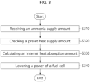
- FIG. 3 is a schematic flowchart describing a method of controlling a system for controlling an ammonia reactor in accordance with embodiments of the present disclosure.
- an ammonia reactor control system may calculate an internal heat absorption amount of the cracker 100 using an internal temperature information of a cracker (e.g., cracker 100 of FIG. 1 ) to temporarily lower a power of the fuel cell.
- a controller may receive an ammonia supply amount (also referred to herein as ammonia supply amount information).
- the controller 120 may receive the ammonia supply amount through an ammonia supplier (e.g., the ammonia supplier 140 of FIG. 2 ).
- the controller 120 may receive the ammonia supply amount information from a separate flow-meter or a supply amount measurement device installed in the ammonia supplier 140.
- the ammonia supplier 140 may include an ammonia supply line.
- the controller 120 may check a preset heat supply amount information (also referred to as preset heat supply amount.
- the ammonia reactor control system 10 may differently adjust a hydrogen supply pattern using the first signal to induce an improved ramping effect in consideration of the stability of a hydrogen reaction. For example, the same total amount of hydrogen may be supplied by changing the pattern.
- the controller 120 may check the preset heat supply amount information from a storage device (e.g., the storage device 150 in FIG. 2 ). In an operation S330, the controller 120 may calculate a heat absorption information in the cracker 100 based on a temperature information received from a sensor (e.g., the sensor 110 in FIG. 2 ).
- a storage device e.g., the storage device 150 in FIG. 2
- the controller 120 may calculate a heat absorption information in the cracker 100 based on a temperature information received from a sensor (e.g., the sensor 110 in FIG. 2 ).
- the controller 120 may temporarily lower the power of the fuel cell 300 by comparing the preset heat supply amount information with the internal heat absorption information of the cracker 100.
- a temporary period may be in a range from about 3 to 5 seconds and may vary depending on experimental values.
- the preset heat supply amount information may correspond to a threshold value of the internal heat absorption amount of the cracker 100.
- the preset heat supply amount may be set to a heat supply amount that can prevent a decrease of the internal temperature of the cracker 100 due to excessive ammonia or excessive hydrogen.
- the controller 120 may determine the first signal based on the temperature information and the ammonia supply amount information. Using the first signal from the controller 120, the ramping effect in the cracker may be controlled through the preset heat supply amount information.
- the controller 120 may increase the internal temperature of the cracker 100 by increasing the hydrogen supply amount through the first signal. Accordingly, the ramping effect in the ammonia reactor control system 10 may be amplified.
- the controller 120 may increase the amount of hydrogen supplied from the fuel cell 300 as the temperature of the cracker 100 decreases. Accordingly, the temperature of the cracker 100 may be rapidly increased by the controller 120. In the determination of the hydrogen supply amount, the controller 120 may change the hydrogen supply pattern to generate a maximum ramping effect in consideration of the hydrogen reaction stability.
- FIG. 4 is a schematic flowchart describing an ammonia pre-heating in a system for controlling an ammonia reactor in accordance with embodiments of the present disclosure.
- the controller may receive a temperature information of ammonia supplied to the inside of the cracker (e.g., the cracker 100 in FIG. 1 ).
- the controller 120 may receive the ammonia temperature information through a separate temperature sensor 60 capable of detecting the temperature of ammonia supplied to the inside the cracker 100.
- the controller 120 may determine a third signal based on the ammonia temperature information.
- the controller 120 may pre-heat ammonia in advance before being supplied to the cracker through the third signal.
- the ammonia reactor control system (e.g., the ammonia reactor control system 10 of FIG. 1 ) may further include a pre-heater 50 that may pre-heat ammonia being supplied into the cracker 100 according to the third signal.
- the pre-heater 50 may be located at an inside or an outside of an ammonia supplier (e.g., the ammonia supplier 140).
- the pre-heater 50 may be placed in any position capable of pre-heating ammonia in the ammonia supplier 140.
- the controller 120 may receive the ammonia temperature information in the ammonia supplier 140 from the temperature sensor 60. Accordingly, the controller 120 may check whether the temperature of ammonia to be supplied to the cracker 100 through the ammonia supplier 140 is lower than a temperature of ammonia already existing in the cracker 100.
- the controller 120 may operate the pre-heater through the third signal to increase the ammonia temperature of the ammonia supplier 140.
- the controller 120 may operate the pre-heater to increase the temperature of ammonia in the ammonia supplier 140 in advance through the third signal.
- factors causing the decrease of the internal temperature in the cracker 100 may be controlled.
- the temperature control may be performed using a mechanism that decomposes ammonia that is an endothermic reaction.
- the pre-heater may include a material having a high thermal conductivity and a large heat capacity.
- the pre-heater may be formed of a material capable of providing a uniform heat transfer when pre-heating ammonia.
- FIG. 5 is a schematic flowchart describing a determination of an ammonia supply amount in a system for controlling an ammonia reactor in accordance with embodiments of the present disclosure.
- the controller may receive a hydrogen supply amount (also referred to as hydrogen supply amount information) from the hydrogen supplier (e.g., the hydrogen supplier 130 of FIG. 2 ).
- the controller 120 may receive the hydrogen supply amount information through a separate flow-meter or a supply amount measurement apparatus installed in the hydrogen supplier 130.
- the controller 120 may determine an ammonia supply amount according to a preset temperature range.
- the controller 120 may determine the ammonia supply amount in the cracker (e.g., the cracker 100 in FIG. 1 ) according to the second signal.
- the controller 120 may check information on the preset temperature range from the storage device (e.g., the storage device 150 of FIG. 2 ).
- the preset temperature range may include a first temperature range and a second temperature range.
- the first temperature range and the second temperature range may be continuous temperature ranges without overlapping each other. That is, a lower limit of the first temperature range may be greater than an upper limit of the second temperature range.
- the controller 120 may determine the ammonia supply amount according to the second signal as a first capacity. In an embodiment, when the temperature of the cracker 100 is within the preset second temperature range, the controller 120 may determine the ammonia supply amount according to the second signal as a second capacity.
- the first capacity may be smaller than the second capacity.
- the first temperature range, the second temperature range, the first capacity and the second capacity may be experimental values and may be stored as preset values according to a user's experiment results.
- a threshold value may be used in which a time or a cost required to increase the internal temperature of the cracker 100 is greater than a cost incurred by stopping the ammonia supply.
- the controller 120 may adjust the ammonia supply amount by reducing or blocking the ammonia supply.
- the controller 120 may adjust the ammonia supply amount based on the second signal.
- the controller 120 may change the ammonia supply amount reduction pattern according to a preset temperature range of the cracker 100 so that a maximum ramping effect may be achieved depending on the situation at the inside of the cracker 100.
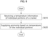
- FIG. 6 is a schematic flowchart describing a determination of an ammonia supply amount based on an individual partial temperature of a cracker in a system for controlling an ammonia reactor in accordance with embodiments of the present disclosure.
- the controller may receive temperature information of individual portions of the cracker (e.g., the cracker 100 of FIG. 1 ).
- the controller 120 may receive internal temperatures including the internal temperatures of the first portion and the second portion of the cracker 100.
- the sensor e.g., the sensor 110 in FIG. 2
- the sensor 110 of FIG. 2 may include a plurality of sensors and may collect temperature information of the first portion and the second portion of the cracker 100. That is, the sensor 110 of FIG. 2 may include, inter alia, a first temperature sensor for measuring the internal temperature of the first portion of the cracker 100, and a second temperature sensor for measuring the internal temperature of the second portion of the cracker 100.
- the first portion and the second portion of the cracker 100 may refer to parts of the cracker 100 that do not overlap with each other.
- the first portion and the second portion may be portions of a region where the ammonia supplier (e.g., the ammonia supplier 140 of FIG. 2 ) and the cracker are connected.
- the sensor 110 may measure the temperatures of individual portions at the inside of the cracker 100 including the first portion and the second portion of the cracker 100.
- the controller 120 may determine the second signal according to the temperatures of the individual portions at the inside of the cracker 100.
- the ammonia reactor control system 10 may change a pattern of a total supply amount of ammonia to the first portion and the second portion.
- the controller 120 may change a supply location of ammonia.
- the controller 120 may determine the supply amount of ammonia to the first portion and the supply amount of ammonia to the second portion among the total supply amount of ammonia differently through the second signal. For example, the controller 120 performs the control to induce the maximum ramping effect for efficiently decomposing or cracking ammonia while ensuring safety and product quality. For example, when the temperature of the first portion is relatively high, a smaller amount of ammonia may be controlled to be supplied to the first portion than that to the second portion.
- the controller 120 may determine the second signal based on the temperature information of the individual portions.
- the controller 120 may use the temperature information collected from each individual portion to adjust the supply amount of ammonia to the first portion and the second portion so that the maximum ramping effect may be achieved.
- the controller 120 may determine the first signal or the second signal based on the temperature information, the ammonia supply amount information and the hydrogen supply amount information. The controller 120 may adjust the supply amount of ammonia or hydrogen to generate the maximum ramping effect based on various information collected by the ammonia reactor control system 10.
- the controller 120 may set the total supply amount of ammonia or hydrogen to generate the maximum ramping effect based on the same information and may change the pattern of supplying ammonia or hydrogen to the cracker 100. For example, the controller 120 may maintain the appropriate internal temperature of the cracker 100 by increasing or decreasing the supply amount of ammonia and/or unreacted hydrogen depending on the temperature of the cracker 100. Additionally, the controller 120 may maintain the internal temperature of the cracker 100 in an appropriate range to reduce the residual ammonia amount.
- the disclosed embodiments may be implemented in the form of a recording medium storing instructions executable by a computer.
- the instructions may be stored in the form of a program code, and a program module may be generated by a processor to perform operations of the disclosed embodiments.
- the recording medium may be implemented in a computer-readable form.
- the computer-readable recording medium includes all types of recording media in which instructions that may be read by a computer are stored.
- the recording medium may include a read only memory (ROM), a random access memory (RAM), a magnetic tape, a magnetic disk, a flash memory, an optical data storage device (150), etc.
Landscapes
- Chemical & Material Sciences (AREA)
- Engineering & Computer Science (AREA)
- Organic Chemistry (AREA)
- Chemical Kinetics & Catalysis (AREA)
- General Chemical & Material Sciences (AREA)
- Sustainable Energy (AREA)
- Sustainable Development (AREA)
- Electrochemistry (AREA)
- Life Sciences & Earth Sciences (AREA)
- Manufacturing & Machinery (AREA)
- Combustion & Propulsion (AREA)
- Health & Medical Sciences (AREA)
- General Health & Medical Sciences (AREA)
- Inorganic Chemistry (AREA)
- Automation & Control Theory (AREA)
- General Physics & Mathematics (AREA)
- Physics & Mathematics (AREA)
- Fuel Cell (AREA)
Abstract
A system (10) for controlling an ammonia reactor includes a sensor (110) measuring an internal temperature of a cracker (100), a controller (120) configured to receive temperature information collected from the sensor (110), a hydrogen supplier (130 configured to determine a hydrogen supply amount into the cracker (100) according to a first signal from the controller (120), and an ammonia supplier (140) configured to determine an ammonia supply amount into the cracker (100) according to a second signal from the controller (120). The controller (120) is configured to receive ammonia supply amount information from the ammonia supplier (140), and to determine the first signal based on the temperature information and the ammonia supply amount information.
Description
- Embodiments of the present disclosure relate generally to a system and method for controlling an ammonia reactor and generating hydrogen.
- In a system for ammonia decomposition, the ammonia decomposition amount may variably depend on the state of a driving vehicle that may employ, e.g., a fuel cell, and the ammonia supply amount may be changed depending on the ammonia cracker temperature also referred to as the ammonia reactor) so that an ammonia decomposition ratio in the reactor due to a change in the reactor temperature can be stabilized.
- In the load-following operation process, when an ammonia supply into the reactor is increased in order to increase a hydrogen production within a short period, a temperature reduction in the reactor may be caused because the supplied ammonia is normally at room temperature.
- When an internal temperature of the reactor is temporarily lowered, the ammonia decomposition ratio may be decreased, which may cause a catalyst deactivation within an inside of the reactor or performance degradation of an entire apparatus. Accordingly, an amount of residual ammonia in the apparatus may be increased. The residual ammonia may be supplied to an adsorption tower or a fuel cell, thereby causing overall performance degradation or unexpected defects of the apparatus.
- According to an embodiment of the present disclosure, there is provided a system for controlling an ammonia reactor having improved process efficiency.
- According to an embodiment of the present disclosure, there is provided a method of generating hydrogen having improved process efficiency.
- The embodiments of the present disclosure are not specifically limited, and other embodiments that are not clearly mentioned will also be understood by those skilled in the art from the following descriptions.
- A system for controlling an ammonia reactor includes a sensor configured to measure an internal temperature of a cracker, a controller configured to receive temperature information collected from the sensor, a hydrogen supplier configured to determine a hydrogen supply amount into the cracker according to a first signal from the controller, and an ammonia supplier configured to determine an ammonia supply amount into the cracker according to a second signal from the controller. The controller is configured to receive ammonia supply amount information from the ammonia supplier, and to determine the first signal based on the temperature information and the ammonia supply amount information.
- In some embodiments, the system may further include a storage device configured to store a preset heat supply amount information to a fuel cell through the cracker. The controller may be configured to check the preset heat supply amount information from the storage device, and to calculate an internal heat absorption information of the cracker based on the temperature information.
- In some embodiments, the controller may be configured to compare the preset heat supply amount information with the internal heat absorption information of the cracker, and to temporarily lower a power of the fuel cell.
- In some embodiments, the reactor may further include a temperature sensor configured to detect a temperature of ammonia supplied into the cracker from the ammonia supplier, and a pre-heater for pre-heating ammonia supplied into the cracker according to a third signal from the controller.
- In some embodiments, the controller may be configured to receive an ammonia temperature information in the ammonia supplier from the temperature sensor, and to determine the third signal for operating the pre-heater based on the ammonia temperature information.
- In some embodiments, the controller may be configured to receive a hydrogen supply amount information from the hydrogen supplier, and to determine the second signal based on the temperature information and the hydrogen supply amount information.
- In some embodiments, the controller may be configured to determine the ammonia supply amount as a first capacity according to the second signal if a temperature of the cracker corresponds to a preset first temperature range, and to determine the ammonia supply amount as a second capacity according to the second signal if the temperature of the cracker corresponds to a preset second temperature range. A lower limit of the first temperature range may be greater than an upper limit of the second temperature range, and the first capacity may be less than the second capacity.
- In some embodiments, the sensor may be configured to measure temperatures of internal portions of the cracker including a first portion and a second portion of the cracker. The ammonia supplier may be connected to the first portion and the second portion. The controller may be configured to determine the second signal based on temperature information of the first portion and the second portion.
- In some embodiments, the controller may be configured to determine the first signal or the second signal based on the temperature information, the ammonia supply amount information and the hydrogen supply amount information.
- In a method of generating hydrogen from an ammonia feed, ammonia is fed to a cracker. Temperature information collected from a sensor that measures an internal temperature of the cracker is received. Ammonia supply amount information is received from an ammonia supplier that determines an ammonia supply amount into the cracker. A hydrogen supply amount information is received from a hydrogen supplier that determines a hydrogen supply amount into the cracker. A first signal or a second signal is provided to the hydrogen supplier or the ammonia supplier based on the temperature information, the ammonia supply amount information and the hydrogen supply amount information.
- According to the above-described embodiments, the ammonia reactor control system may be configured to increase or decrease a supply amount of ammonia and/or an unreacted hydrogen depending on a temperature of a cracker to maintain a proper internal temperature of the cracker. Accordingly, a reduction of a reaction rate in the cracker may be prevented.
- In some embodiments, the ammonia reactor control system may appropriately be configured to maintain an internal temperature in the cracker to reduce an amount of a residual ammonia. Accordingly, performance deterioration of the system due to the residual ammonia may be prevented.
- The effects of the embodiment of the present disclosure are not limited to those mentioned above, and other effects that are not specifically mentioned will be clearly understood by those skilled in the art from the following descriptions.
-
-
FIG. 1 is a block diagram of a system for controlling an ammonia reactor in accordance with embodiments of the present disclosure. -
FIG. 2 is a schematic block diagram illustrating components of a system for controlling an ammonia reactor in accordance with embodiments of the present disclosure. -
FIG. 3 is a schematic flowchart describing a method of controlling a system for controlling an ammonia reactor in accordance with embodiments of the present disclosure. -
FIG. 4 is a schematic flowchart describing an ammonia pre-heating in a system for controlling an ammonia reactor in accordance with embodiments of the present disclosure. -
FIG. 5 is a schematic flowchart describing determination of an ammonia supply amount in a system for controlling an ammonia reactor in accordance with embodiments of the present disclosure. -
FIG. 6 is a schematic flowchart describing determination of an ammonia supply amount based on an individual partial temperature of a cracker in a system for controlling an ammonia reactor in accordance with embodiments of the present disclosure. - Throughout the present disclosure, the same reference numerals refer to the same elements. The present disclosure does not describe all elements of the embodiments, and general contents in the technical field to which the present disclosure pertains or repeated contents between embodiments may be omitted. The terms "part," "module," "member," "block," and the like, when used herein may be implemented by software or hardware, and according to embodiments, a plurality of the "'part," "module," "member," "block," and the like, may be implemented as a single element, or may include a plurality of elements.
- Throughout the specification, when an element or portion is recited as being "connected" to another element or portion, the recitation includes a direct connection, and an indirect connection, and an indirect connection may include a wireless communication network.
- When an element is recited to "include" another element, the elements may include other elements, rather than excluding other elements, unless otherwise described.
- Throughout the specification, when an element is recited to be positioned "on" another element, the recitation includes a case where an element is in contact with another element, and a case where another element is present between the two elements.
- Terms such as "a first," "a second," and the like are used to distinguish one element from another element, and the elements are not limited by the terms.
- As used herein, the singular forms "a," "an" and "the" are intended to include the plural forms as well, unless the context clearly indicates otherwise.
- A reference numeral designating an operation is used for convenience of descriptions and is not intended to limit the order of the operation, and the operation may be performed differently from the specified order unless a specific order is clearly described herein.
- Hereinafter, operation mechanisms and embodiments of the present disclosure will be described with reference to the accompanying drawings.
- In the present specification, "the device (or an apparatus) according to the present disclosure" includes all various devices capable of performing arithmetic processing and providing a result to a user. For example, the device according to the present disclosure may include all of a computer, a server device and a portable terminal, or may include any one of the forms.
- Here, the computer may include, e.g., a notebook computer, a desktop, a laptop computer, a tablet PC, a slate PC, etc., equipped with a web browser.
- The server device is a server that processes information by communicating with an external device, and may include an application server, a computing server, a database server, a file server, a game server, a mail server, a proxy server, a web server, etc.
- For example, the portable terminal may be a wireless communication device having portability and mobility. The portable terminal may include all types of handheld-based wireless communication devices such as a personal communication system (PCS), a global system for mobile communications (GSM), a personal digital cell (PDC), a personal handy phone system (PHS), a personal digital assistant (PDA), an International Mobile Telecommunication (IMT)-2000, Code Division Multiple Access (CDMA)-2000, W-CDMA (W-Code Division Multiple Access), a wireless broadband Internet (WiBro) terminal, a smartphone, etc., and may include wearable devices such as a watch, a ring, a bracelet, an anklet, a necklace, glasses, contact lenses, or a head-mounted-device (HMD).
-
FIG. 1 is a block diagram of a system for controlling an ammonia reactor in accordance with embodiments of the present disclosure. - Referring to
FIG. 1 , a system for controlling an ammonia reactor system 10 (hereinafter, referred to as the ammonia reactor control system) includes acracker 100, an absorber 200 and afuel cell 300. Each of the components/nodes may exchange data with different components/nodes. The components/nodes may be connected to each other through a network. - The ammonia
reactor control system 10 according to embodiments of the present disclosure may receive and decompose ammonia (NH3) through thecracker 100. When an internal temperature of thecracker 100 is temporarily lowered, the ammonia decomposition ratio may be lowered due to catalyst deactivation or performance degradation in thecracker 100. Accordingly, the residual ammonia in thecracker 100 may be relatively increased. - In some embodiments, the
cracker 100 may receive ammonia to produce hydrogen (H2), nitrogen (N2) and ammonia (NH3) as decomposition products. Thereafter, hydrogen and nitrogen pass through theabsorber 200 and are supplied to thefuel cell 300 where the hydrogen and nitrogen are utilized to generate power which is supplied to a battery. Hence, the absorber may comprise an absorbent that preferentially absorbs ammonia while allowing the purified nitrogen and hydrogen to pass through. The purified mixture of hydrogen and nitrogen is then fed to thefuel cell 300. In thefuel cell 300 the hydrogen may serve as the fuel while the nitrogen may serve as the oxidizing agent. - In some embodiments, the
fuel cell 300 may completely combust an unconverted hydrogen by supplying nitrogen and the unconverted hydrogen back into thecracker 100. Accordingly, the ammoniareactor control system 10 may combust by-products generated by an imbalance between materials supplied into thecracker 100 again through a feedback. -
FIG. 2 is a schematic block diagram illustrating components of a system for controlling an ammonia reactor in accordance with embodiments of the present disclosure. - Referring to
FIG. 2 , the ammoniareactor control system 10 may include thecracker 100, asensor 110, acontroller 120, ahydrogen supplier 130, anammonia supplier 140 and astorage device 150. An internal structure included in the ammoniareactor control system 10 may include theabsorber 200 and thefuel cell 300 as shown inFIG. 1 but is the embodiments are not limited thereto. - In some embodiments, the function of the
controller 120 may be performed through a separate processing server or a cloud server instead of thecontroller 120. - In some embodiments, a reactor of the ammonia
reactor control system 10 may refer to an apparatus such as acracker 100. - The
controller 120 may receive ammonia supply amount information from theammonia supplier 140. Thecontroller 120 may receive hydrogen supply amount information from thehydrogen supplier 130. In some embodiments, thecontroller 120 may receive supply amounts of ammonia and hydrogen supplied into thecracker 100 of the ammoniareactor control system 10 from theammonia supplier 140 and thehydrogen supplier 130, respectively. - The
controller 120 may receive internal temperature information of thecracker 100 from thesensor 110. Thecontroller 120 may receive internal temperatures of a first portion and a second portion of thecracker 100. Thesensor 110 may include a plurality of sensors to collect the temperature information on the first and second portions of thecracker 100, respectively. The first portion and the second portion may refer to portions of thecracker 100 that may not overlap with each other. In some embodiments, the first portion and the second portion may be a portion of a part where theammonia supplier 140 and thecracker 100 may be connected. - In some embodiments, the
hydrogen supplier 130 may determine an amount of hydrogen supplied into thecracker 100 according to a first signal from thecontroller 120. The amount of hydrogen supplied to thecracker 100 may be adjusted according to the first signal from thecontroller 120. - In some embodiments, the
ammonia supplier 140 may determine an amount of ammonia supplied into thecracker 100 according to a second signal from thecontroller 120. The amount of ammonia supplied to thecracker 100 may be adjusted according to the second signal from thecontroller 120. - In some embodiments, the
storage device 150 may store data supporting various functions of the ammoniareactor control system 10 and a program for the operation of thecontroller 120. Thestorage device 150 may store input/output data (e.g., an image, a video, etc.). Thestorage device 150 may store an application program or an application driven in the ammoniareactor control system 10, and data and instructions for the operation of the ammoniareactor control system 10. At least one of the application programs may be downloaded from an external server through a wireless communication. - The
storage device 150 may include at least one type of storage media selected from a network attached storage (NAS), a flash memory type, a hard disk type, a solid state disk (SSD) type, a silicon disk drive (SSD) type, a multimedia card micro type, a card type memory (e.g., an SD or XD memory, etc.), a random access memory (RAM), a static random access memory (SRAM), a read-only memory (ROM), an electrically erasable programmable read-only memory (EEPROM), a programmable read-only memory (PROM), a magnetic memory, a magnetic disk and an optical disk. Thestorage device 150 may include a database separated from the ammoniareactor control system 10, and may be wire-connected or wireless-connected to the ammoniareactor control system 10. - The ammonia
reactor control system 10 may further include an output element (not illustrated). The output element may generate an output related to a visual sense, a hearing sense, or a touch sense, and may include a display device. - The display device may form a mutual-layered structure with a touch sensor or may be provided as an integral structure with the touch sensor to implement a touch screen. The touch screen may be provided as a user input element that provides an input interface between the ammonia
reactor control system 10 and the user, and may provide an output interface between the ammoniareactor control system 10 and the user. - The display device may display (output) information processed in the ammonia
reactor control system 10. For example, the display device may display an execution screen information of the application program (e.g., the application) driven in the ammoniareactor control system 10, or information of a user interface (UI) or graphic user interface (GUI) information according to the execution screen information. - At least one of the elements may be added or deleted corresponding to the performance of the elements shown in
FIG. 2 . Further, it may be easily understood by those ordinarily skilled in the art that mutual positions of the various elements may be changed corresponding to the performance or the structure of the ammoniareactor control system 10. - Each element shown in
FIG. 2 may be implemented via software and/or hardware such as a field programmable gate array (FPGA) and an application specific integrated circuit (ASIC). -
FIG. 3 is a schematic flowchart describing a method of controlling a system for controlling an ammonia reactor in accordance with embodiments of the present disclosure. - Referring to
FIG. 3 , an ammonia reactor control system (e.g., the ammoniareactor control system 10 ofFIG. 1 ) may calculate an internal heat absorption amount of thecracker 100 using an internal temperature information of a cracker (e.g.,cracker 100 ofFIG. 1 ) to temporarily lower a power of the fuel cell. - In an operation S310, a controller (e.g., the
controller 120 ofFIG. 2 ) may receive an ammonia supply amount (also referred to herein as ammonia supply amount information). Thecontroller 120 may receive the ammonia supply amount through an ammonia supplier (e.g., theammonia supplier 140 ofFIG. 2 ). Thecontroller 120 may receive the ammonia supply amount information from a separate flow-meter or a supply amount measurement device installed in theammonia supplier 140. Theammonia supplier 140 may include an ammonia supply line. - In an operation S320, the
controller 120 may check a preset heat supply amount information (also referred to as preset heat supply amount. The ammoniareactor control system 10 may differently adjust a hydrogen supply pattern using the first signal to induce an improved ramping effect in consideration of the stability of a hydrogen reaction. For example, the same total amount of hydrogen may be supplied by changing the pattern. - The
controller 120 may check the preset heat supply amount information from a storage device (e.g., thestorage device 150 inFIG. 2 ). In an operation S330, thecontroller 120 may calculate a heat absorption information in thecracker 100 based on a temperature information received from a sensor (e.g., thesensor 110 inFIG. 2 ). - In an operation S340, the
controller 120 may temporarily lower the power of thefuel cell 300 by comparing the preset heat supply amount information with the internal heat absorption information of thecracker 100. For example, a temporary period may be in a range from about 3 to 5 seconds and may vary depending on experimental values. The preset heat supply amount information may correspond to a threshold value of the internal heat absorption amount of thecracker 100. - In some embodiments, the preset heat supply amount may be set to a heat supply amount that can prevent a decrease of the internal temperature of the
cracker 100 due to excessive ammonia or excessive hydrogen. - The
controller 120 may determine the first signal based on the temperature information and the ammonia supply amount information. Using the first signal from thecontroller 120, the ramping effect in the cracker may be controlled through the preset heat supply amount information. - In some embodiments, if the internal heat absorption of the cracker is lower than the preset heat supply amount, the
controller 120 may increase the internal temperature of thecracker 100 by increasing the hydrogen supply amount through the first signal. Accordingly, the ramping effect in the ammoniareactor control system 10 may be amplified. - In some embodiments, the
controller 120 may increase the amount of hydrogen supplied from thefuel cell 300 as the temperature of thecracker 100 decreases. Accordingly, the temperature of thecracker 100 may be rapidly increased by thecontroller 120. In the determination of the hydrogen supply amount, thecontroller 120 may change the hydrogen supply pattern to generate a maximum ramping effect in consideration of the hydrogen reaction stability. -
FIG. 4 is a schematic flowchart describing an ammonia pre-heating in a system for controlling an ammonia reactor in accordance with embodiments of the present disclosure. - In an operation S410, the controller (e.g., the
controller 120 inFIG. 2 ) may receive a temperature information of ammonia supplied to the inside of the cracker (e.g., thecracker 100 inFIG. 1 ). Thecontroller 120 may receive the ammonia temperature information through aseparate temperature sensor 60 capable of detecting the temperature of ammonia supplied to the inside thecracker 100. - In an operation S420, the
controller 120 may determine a third signal based on the ammonia temperature information. Thecontroller 120 may pre-heat ammonia in advance before being supplied to the cracker through the third signal. The ammonia reactor control system (e.g., the ammoniareactor control system 10 ofFIG. 1 ) may further include a pre-heater 50 that may pre-heat ammonia being supplied into thecracker 100 according to the third signal. The pre-heater 50 may be located at an inside or an outside of an ammonia supplier (e.g., the ammonia supplier 140). The pre-heater 50 may be placed in any position capable of pre-heating ammonia in theammonia supplier 140. - In some embodiments, the
controller 120 may receive the ammonia temperature information in theammonia supplier 140 from thetemperature sensor 60. Accordingly, thecontroller 120 may check whether the temperature of ammonia to be supplied to thecracker 100 through theammonia supplier 140 is lower than a temperature of ammonia already existing in thecracker 100. - In an embodiment, when the ammonia temperature of the
ammonia supplier 140 is lower than the ammonia temperature in thecracker 100, thecontroller 120 may operate the pre-heater through the third signal to increase the ammonia temperature of theammonia supplier 140. - In an embodiment, when the temperature of the ammonia in the
ammonia supplier 140 to be supplied into thecracker 100 is low, thecontroller 120 may operate the pre-heater to increase the temperature of ammonia in theammonia supplier 140 in advance through the third signal. - As described above, factors causing the decrease of the internal temperature in the
cracker 100 may be controlled. For example, the temperature control may be performed using a mechanism that decomposes ammonia that is an endothermic reaction. - In some embodiments, the pre-heater may include a material having a high thermal conductivity and a large heat capacity. The pre-heater may be formed of a material capable of providing a uniform heat transfer when pre-heating ammonia.
-
FIG. 5 is a schematic flowchart describing a determination of an ammonia supply amount in a system for controlling an ammonia reactor in accordance with embodiments of the present disclosure. - In an operation S510, the controller (e.g., the
controller 120 ofFIG. 2 ) may receive a hydrogen supply amount (also referred to as hydrogen supply amount information) from the hydrogen supplier (e.g., thehydrogen supplier 130 ofFIG. 2 ). Thecontroller 120 may receive the hydrogen supply amount information through a separate flow-meter or a supply amount measurement apparatus installed in thehydrogen supplier 130. - In operation S520, the
controller 120 may determine an ammonia supply amount according to a preset temperature range. Thecontroller 120 may determine the ammonia supply amount in the cracker (e.g., thecracker 100 inFIG. 1 ) according to the second signal. - In some embodiments, the
controller 120 may check information on the preset temperature range from the storage device (e.g., thestorage device 150 ofFIG. 2 ). The preset temperature range may include a first temperature range and a second temperature range. For example, the first temperature range and the second temperature range may be continuous temperature ranges without overlapping each other. That is, a lower limit of the first temperature range may be greater than an upper limit of the second temperature range. - In an embodiment, when the temperature of the
cracker 100 is within the first preset temperature range, thecontroller 120 may determine the ammonia supply amount according to the second signal as a first capacity. In an embodiment, when the temperature of thecracker 100 is within the preset second temperature range, thecontroller 120 may determine the ammonia supply amount according to the second signal as a second capacity. The first capacity may be smaller than the second capacity. The first temperature range, the second temperature range, the first capacity and the second capacity may be experimental values and may be stored as preset values according to a user's experiment results. - In some embodiments, a threshold value may be used in which a time or a cost required to increase the internal temperature of the
cracker 100 is greater than a cost incurred by stopping the ammonia supply. When the threshold value is reached, thecontroller 120 may adjust the ammonia supply amount by reducing or blocking the ammonia supply. Thecontroller 120 may adjust the ammonia supply amount based on the second signal. According to the embodiment ofFIG. 5 , when reducing the ammonia supply amount, thecontroller 120 may change the ammonia supply amount reduction pattern according to a preset temperature range of thecracker 100 so that a maximum ramping effect may be achieved depending on the situation at the inside of thecracker 100. -
FIG. 6 is a schematic flowchart describing a determination of an ammonia supply amount based on an individual partial temperature of a cracker in a system for controlling an ammonia reactor in accordance with embodiments of the present disclosure. - In an operation S610, the controller (e.g., the
controller 120 ofFIG. 2 ) may receive temperature information of individual portions of the cracker (e.g., thecracker 100 ofFIG. 1 ). Thecontroller 120 may receive internal temperatures including the internal temperatures of the first portion and the second portion of thecracker 100. In some embodiments, the sensor (e.g., thesensor 110 inFIG. 2 ) may include a plurality of sensors and may collect temperature information of the first portion and the second portion of thecracker 100. That is, thesensor 110 ofFIG. 2 may include, inter alia, a first temperature sensor for measuring the internal temperature of the first portion of thecracker 100, and a second temperature sensor for measuring the internal temperature of the second portion of thecracker 100. - The first portion and the second portion of the
cracker 100 may refer to parts of thecracker 100 that do not overlap with each other. In some embodiments, the first portion and the second portion may be portions of a region where the ammonia supplier (e.g., theammonia supplier 140 ofFIG. 2 ) and the cracker are connected. - The
sensor 110 may measure the temperatures of individual portions at the inside of thecracker 100 including the first portion and the second portion of thecracker 100. Thecontroller 120 may determine the second signal according to the temperatures of the individual portions at the inside of thecracker 100. - According to the second signal, the ammonia
reactor control system 10 may change a pattern of a total supply amount of ammonia to the first portion and the second portion. - In an embodiment, the
controller 120 may change a supply location of ammonia. When the temperature of the first portion is higher than the temperature of the second portion, thecontroller 120 may determine the supply amount of ammonia to the first portion and the supply amount of ammonia to the second portion among the total supply amount of ammonia differently through the second signal. For example, thecontroller 120 performs the control to induce the maximum ramping effect for efficiently decomposing or cracking ammonia while ensuring safety and product quality. For example, when the temperature of the first portion is relatively high, a smaller amount of ammonia may be controlled to be supplied to the first portion than that to the second portion. - In an operation S620, the
controller 120 may determine the second signal based on the temperature information of the individual portions. Thecontroller 120 may use the temperature information collected from each individual portion to adjust the supply amount of ammonia to the first portion and the second portion so that the maximum ramping effect may be achieved. - In some embodiments, the
controller 120 may determine the first signal or the second signal based on the temperature information, the ammonia supply amount information and the hydrogen supply amount information. Thecontroller 120 may adjust the supply amount of ammonia or hydrogen to generate the maximum ramping effect based on various information collected by the ammoniareactor control system 10. - In an embodiment, the
controller 120 may set the total supply amount of ammonia or hydrogen to generate the maximum ramping effect based on the same information and may change the pattern of supplying ammonia or hydrogen to thecracker 100. For example, thecontroller 120 may maintain the appropriate internal temperature of thecracker 100 by increasing or decreasing the supply amount of ammonia and/or unreacted hydrogen depending on the temperature of thecracker 100. Additionally, thecontroller 120 may maintain the internal temperature of thecracker 100 in an appropriate range to reduce the residual ammonia amount. - In some embodiments, the disclosed embodiments may be implemented in the form of a recording medium storing instructions executable by a computer. The instructions may be stored in the form of a program code, and a program module may be generated by a processor to perform operations of the disclosed embodiments. The recording medium may be implemented in a computer-readable form.
- The computer-readable recording medium includes all types of recording media in which instructions that may be read by a computer are stored. For example, the recording medium may include a read only memory (ROM), a random access memory (RAM), a magnetic tape, a magnetic disk, a flash memory, an optical data storage device (150), etc.
Claims (10)
- A system (10) for controlling an ammonia reactor, the system (10) comprising:a sensor (110) configured to measure an internal temperature of a cracker (100);a controller (120) configured to receive temperature information collected from the sensor (110);a hydrogen supplier (130) configured to determine a hydrogen supply amount into the cracker (100) according to a first signal from the controller (120); andan ammonia supplier (140) configured to determine an ammonia supply amount into the cracker (100) according to a second signal from the controller (120),wherein the controller (120) is configured to receive ammonia supply amount information from the ammonia supplier (140), and to determine the first signal based on the temperature information and the ammonia supply amount information.
- The system (10) for controlling an ammonia reactor of claim 1, further comprising a storage device configured to store preset heat supply amount information to a fuel cell (300) through the cracker (100),
wherein the controller (120) is configured to check the preset heat supply amount information from the storage device (150), and to calculate internal heat absorption information of the cracker (100) based on the temperature information. - The system (10) for controlling an ammonia reactor of claim 2, wherein the controller (120) is configured to compare the preset heat supply amount information with the internal heat absorption information of the cracker (100), and to temporarily lower a power of the fuel cell (300).
- The system (10) for controlling an ammonia reactor of any one of claims 1 to 3, further comprising:a temperature sensor (60) configured to detect a temperature of ammonia supplied into the cracker (100) from the ammonia supplier (140); anda pre-heater configured to pre-heat ammonia supplied into the cracker (100) according to a third signal from the controller (120).
- The system (10) for controlling an ammonia reactor of claim 4, wherein the controller (120) is configured to receive ammonia temperature information in the ammonia supplier (140) from the temperature sensor (60), and to determine the third signal for operating the pre-heater based on the ammonia temperature information.
- The system (10) for controlling an ammonia reactor of any one of claims 1 to 5, wherein the controller (120) is configured to receive hydrogen supply amount information from the hydrogen supplier (130), and to determine the second signal based on the temperature information and the hydrogen supply amount information.
- The system (10) for controlling an ammonia reactor of claim 6, wherein the controller (120) is configured to determine the ammonia supply amount as a first capacity according to the second signal when a temperature of the cracker corresponds to a preset first temperature range, and to determine the ammonia supply amount as a second capacity according to the second signal when the temperature of the cracker corresponds to a preset second temperature range,
wherein a lower limit of the first temperature range is greater than an upper limit of the second temperature range, and the first capacity is less than the second capacity. - The system (10) for controlling an ammonia reactor of any one of claims 6 and 7, wherein the sensor is configured to measure temperatures of internal portions including a first portion and a second portion of the cracker (100),the ammonia supplier (140) is connected to the first portion and the second portion, andthe controller (120) is configured to determine the second signal based on temperature information of the first portion and the second portion.
- The system (10) for controlling an ammonia reactor of any one of claims 6 to 8, wherein the controller (120) is configured to determine the first signal or the second signal based on the temperature information, the ammonia supply amount information and the hydrogen supply amount information.
- A method of generating hydrogen from an ammonia feed, the method comprising:feeding ammonia to a cracker (100);receiving temperature information collected from a sensor (110) that measures an internal temperature of the cracker (100);receiving ammonia supply amount information from an ammonia supplier (140) that determines an ammonia supply amount into the cracker (100);receiving hydrogen supply amount information from a hydrogen supplier (130) that determines a hydrogen supply amount into the cracker (100); andproviding a first signal or a second signal to the hydrogen supplier (130) or the ammonia supplier (140) based on the temperature information, the ammonia supply amount information and the hydrogen supply amount information.
Applications Claiming Priority (1)
| Application Number | Priority Date | Filing Date | Title |
|---|---|---|---|
| KR1020230095551A KR102692663B1 (en) | 2023-07-21 | 2023-07-21 | System for controlling ammonia reactor based on gas ratio in cracker and method using the same |
Publications (1)
| Publication Number | Publication Date |
|---|---|
| EP4495058A1 true EP4495058A1 (en) | 2025-01-22 |
Family
ID=91899183
Family Applications (1)
| Application Number | Title | Priority Date | Filing Date |
|---|---|---|---|
| EP24187550.9A Pending EP4495058A1 (en) | 2023-07-21 | 2024-07-09 | System for controlling ammonia reactor and method of generating hydrogen |
Country Status (6)
| Country | Link |
|---|---|
| US (1) | US20250026634A1 (en) |
| EP (1) | EP4495058A1 (en) |
| JP (1) | JP2025016376A (en) |
| KR (1) | KR102692663B1 (en) |
| CN (1) | CN119336098A (en) |
| AU (1) | AU2024204976B2 (en) |
Citations (4)
| Publication number | Priority date | Publication date | Assignee | Title |
|---|---|---|---|---|
| US20110008694A1 (en) * | 2008-03-18 | 2011-01-13 | Toyota Jidosha Kabushiki Kaisha | Hydrogen generator, ammonia-burning internal combustion engine, and fuel cell |
| US20120167840A1 (en) * | 2010-12-30 | 2012-07-05 | Toyota Jidosha Kabushiki Kaisha | Hydrogen generator and internal combustion engine provided with hydrogen generator |
| WO2017154732A1 (en) * | 2016-03-07 | 2017-09-14 | 昭和電工株式会社 | Device for decomposing ammonia, and device for manufacturing hydrogen gas |
| CN115513502A (en) * | 2022-09-29 | 2022-12-23 | 佛山仙湖实验室 | PEMFC system for high-pressure ammonia cracking and front-mounted ammonia recovery and back-mounted hydrogen recovery and operation method |
Family Cites Families (3)
| Publication number | Priority date | Publication date | Assignee | Title |
|---|---|---|---|---|
| KR102256907B1 (en) * | 2019-12-24 | 2021-05-27 | (주)원익머트리얼즈 | On-site Hydrogen filling station |
| KR102920643B1 (en) * | 2020-07-02 | 2026-02-02 | 삼성중공업 주식회사 | Ammonia fuel power generating unit |
| KR102520201B1 (en) * | 2021-06-01 | 2023-04-11 | 대우조선해양 주식회사 | Fuel cell generation system and vessel including the same |
-
2023
- 2023-07-21 KR KR1020230095551A patent/KR102692663B1/en active Active
-
2024
- 2024-07-09 EP EP24187550.9A patent/EP4495058A1/en active Pending
- 2024-07-09 CN CN202410910886.7A patent/CN119336098A/en active Pending
- 2024-07-11 US US18/769,392 patent/US20250026634A1/en active Pending
- 2024-07-18 JP JP2024115003A patent/JP2025016376A/en active Pending
- 2024-07-19 AU AU2024204976A patent/AU2024204976B2/en active Active
Patent Citations (4)
| Publication number | Priority date | Publication date | Assignee | Title |
|---|---|---|---|---|
| US20110008694A1 (en) * | 2008-03-18 | 2011-01-13 | Toyota Jidosha Kabushiki Kaisha | Hydrogen generator, ammonia-burning internal combustion engine, and fuel cell |
| US20120167840A1 (en) * | 2010-12-30 | 2012-07-05 | Toyota Jidosha Kabushiki Kaisha | Hydrogen generator and internal combustion engine provided with hydrogen generator |
| WO2017154732A1 (en) * | 2016-03-07 | 2017-09-14 | 昭和電工株式会社 | Device for decomposing ammonia, and device for manufacturing hydrogen gas |
| CN115513502A (en) * | 2022-09-29 | 2022-12-23 | 佛山仙湖实验室 | PEMFC system for high-pressure ammonia cracking and front-mounted ammonia recovery and back-mounted hydrogen recovery and operation method |
Also Published As
| Publication number | Publication date |
|---|---|
| KR102692663B1 (en) | 2024-08-06 |
| JP2025016376A (en) | 2025-01-31 |
| AU2024204976B2 (en) | 2026-01-15 |
| CN119336098A (en) | 2025-01-21 |
| US20250026634A1 (en) | 2025-01-23 |
| AU2024204976A1 (en) | 2025-02-13 |
Similar Documents
| Publication | Publication Date | Title |
|---|---|---|
| EP2990927B1 (en) | Portable electronic device and method of controlling the display of information | |
| US9230507B2 (en) | System and method for transitioning an electronic device from a first power mode to a second power mode | |
| US9229567B2 (en) | Electronic device including touch-sensitive display | |
| KR101712846B1 (en) | Mechanism for facilitating efficent operations paths for storage devices in computing systems | |
| US10180780B2 (en) | Portable electronic device including touch-sensitive display and method of controlling selection of information | |
| JP2016118564A (en) | Device, method, and graphical user interface for location-based data collection | |
| US20140043247A1 (en) | Electronic device including touch-sensitive display and method of detecting touches | |
| JP2013106348A (en) | Apparatus and method for saving power in portable terminal | |
| CA2838769C (en) | Touch display with variable touch-scan rate | |
| US20140181726A1 (en) | Method and electronic device for providing quick launch access and storage medium | |
| EP3043302B1 (en) | Electronic device and method of controlling display of information | |
| US20150062059A1 (en) | Electronic device including touch-sensitive display and method of detecting touches | |
| US9214131B2 (en) | Non-volatile display accessory controlled and powered by a mobile device | |
| WO2021233291A1 (en) | Screen capture method and apparatus, and electronic device | |
| EP4495058A1 (en) | System for controlling ammonia reactor and method of generating hydrogen | |
| US20150317228A1 (en) | Mechanism for facilitating write tracking for following data eye movements across changing thermal conditions in memory systems | |
| US20160070297A1 (en) | Methods and systems for communication management between an electronic device and a wearable electronic device | |
| EP4495056A2 (en) | Hydrogen cracking apparatus, hydrogen cracking method using the same and energy generation system | |
| KR20210105720A (en) | Method for controlling wearable device and apparatus thereof | |
| EP4495057A2 (en) | System for decomposing ammonia and method of decomposing ammonia | |
| AU2024204975B2 (en) | Hydrogen cracking apparatus, hydrogen cracking method using the same and energy generation system | |
| KR102301843B1 (en) | Method for improving performance of a wireless communication system in accordance with a configuration and an electronic device implementing the same | |
| Conroy | Inside China's giant underground neutrino lab. | |
| US10122786B2 (en) | Electronic device and method of managing data transfer | |
| WO2017166067A1 (en) | Recharging system |
Legal Events
| Date | Code | Title | Description |
|---|---|---|---|
| PUAI | Public reference made under article 153(3) epc to a published international application that has entered the european phase |
Free format text: ORIGINAL CODE: 0009012 |
|
| STAA | Information on the status of an ep patent application or granted ep patent |
Free format text: STATUS: REQUEST FOR EXAMINATION WAS MADE |
|
| 17P | Request for examination filed |
Effective date: 20240709 |
|
| AK | Designated contracting states |
Kind code of ref document: A1 Designated state(s): AL AT BE BG CH CY CZ DE DK EE ES FI FR GB GR HR HU IE IS IT LI LT LU LV MC ME MK MT NL NO PL PT RO RS SE SI SK SM TR |