EP4495043A1 - Hoist and elevator - Google Patents
Hoist and elevator Download PDFInfo
- Publication number
- EP4495043A1 EP4495043A1 EP22932155.9A EP22932155A EP4495043A1 EP 4495043 A1 EP4495043 A1 EP 4495043A1 EP 22932155 A EP22932155 A EP 22932155A EP 4495043 A1 EP4495043 A1 EP 4495043A1
- Authority
- EP
- European Patent Office
- Prior art keywords
- housing
- main shaft
- hoist
- stators
- air
- Prior art date
- Legal status (The legal status is an assumption and is not a legal conclusion. Google has not performed a legal analysis and makes no representation as to the accuracy of the status listed.)
- Pending
Links
Images



Classifications
-
- B—PERFORMING OPERATIONS; TRANSPORTING
- B66—HOISTING; LIFTING; HAULING
- B66B—ELEVATORS; ESCALATORS OR MOVING WALKWAYS
- B66B11/00—Main component parts of lifts in, or associated with, buildings or other structures
- B66B11/04—Driving gear ; Details thereof, e.g. seals
- B66B11/043—Driving gear ; Details thereof, e.g. seals actuated by rotating motor; Details, e.g. ventilation
- B66B11/0438—Driving gear ; Details thereof, e.g. seals actuated by rotating motor; Details, e.g. ventilation with a gearless driving, e.g. integrated sheave, drum or winch in the stator or rotor of the cage motor
-
- H—ELECTRICITY
- H02—GENERATION; CONVERSION OR DISTRIBUTION OF ELECTRIC POWER
- H02K—DYNAMO-ELECTRIC MACHINES
- H02K5/00—Casings; Enclosures; Supports
- H02K5/04—Casings or enclosures characterised by the shape, form or construction thereof
- H02K5/20—Casings or enclosures characterised by the shape, form or construction thereof with channels or ducts for flow of cooling medium
- H02K5/207—Casings or enclosures characterised by the shape, form or construction thereof with channels or ducts for flow of cooling medium with openings in the casing specially adapted for ambient air
-
- H—ELECTRICITY
- H02—GENERATION; CONVERSION OR DISTRIBUTION OF ELECTRIC POWER
- H02K—DYNAMO-ELECTRIC MACHINES
- H02K9/00—Arrangements for cooling or ventilating
- H02K9/02—Arrangements for cooling or ventilating by ambient air flowing through the machine
- H02K9/04—Arrangements for cooling or ventilating by ambient air flowing through the machine having means for generating a flow of cooling medium
Definitions
- the present invention relates to a hoist and an elevator.
- a hoist for an elevator has been required to be downsized in recent years.
- a downsized hoist reduces the heat dissipation area of a motor.
- a hoist with an improved output increases the amount of heat generation.
- a downsized hoist causes a problem in stabilizing motor performance.
- a hoist that sends cooling air between a rotor and a stator is considered (see Patent Literature 1).
- the hoist described in Patent Literature 1 includes a blower blade on an end surface of a rotor. This causes the wind traveling in a rotation axis direction of the rotor with the rotation of the rotor to flow between the rotor and the stator.
- Patent Literature 1 JP 2016-220370 A
- An object of the present invention is to provide a hoist and an elevator capable of stabilizing a cooling effect in consideration of the above problems.
- a hoist includes a housing provided with a plurality of stators, a main shaft supported by the housing, and a rotating body supported by the main shaft.
- the rotating body includes a sheave around which a main rope is wound and a rotor facing the plurality of stators, and the rotating body rotates with respect to the housing.
- the rotating body has a boss portion fitted to the main shaft, a rotating plate portion, a peripheral wall portion, and a plurality of ribs.
- the rotating plate portion is formed in a ring shape continuous with an outer peripheral portion of the boss portion and concentric with the main shaft.
- the peripheral wall portion protrudes from the outer periphery of the rotating plate portion toward the housing.
- the plurality of ribs are provided on an inner surface that is a surface of the rotating plate portion on the housing side, and are radially disposed around the boss portion.
- the rotating plate portion has an intake hole for taking air from the outside to the housing side.
- the housing has an exhaust hole located outside the intake hole in the radial direction of the main shaft.
- An air guide portion that is a curved surface for guiding air entering the housing side from the intake hole to the stator side is formed at a corner portion formed by an inner surface of the rotating plate portion and an inner peripheral surface of the peripheral wall portion.
- An elevator includes a car, a counterweight linked to the car via a main rope, and the hoist around which the main rope is wound.
- the hoist and the elevator having the above configuration can stabilize the cooling effect.
- Fig. 1 is an overall configuration diagram of an elevator according to the first embodiment.
- an elevator 1 is installed in a hoistway 110 formed in a building structure.
- the elevator 1 includes a car 120 on which people and luggage are to be loaded, a main rope 130, a counterweight 140, and a hoist 100.
- a machine room 160 is provided at the top of the hoistway 110.
- the hoist 100 is disposed in the machine room 160.
- the main rope 130 is wound around the hoist 100.
- the hoist 100 is a device that winds up the main rope 130 to raise and lower the car 120.
- a diverting pulley 150 is provided near the hoist 100.
- the main rope 130 is loaded on the diverting pulley 150.
- the car 120 is formed in a substantially hollow rectangular parallelepiped shape.
- the car 120 is linked to the counterweight 140 via the main rope 130.
- the hoist 100 winds up the main rope 130, the car 120 and the counterweight 140 lift and lower in opposite directions.
- the mass of the counterweight 140 is set to be substantially the same as the mass of the car 120 with no load.
- the tension ratio between the main rope 130 on the car 120 side and the main rope 130 on the counterweight 140 side is 1. This makes it possible to suppress the output of the hoist 100 at the time of no load.
- Fig. 2 is a longitudinal sectional view of the hoist 100.
- Fig. 3 is a perspective view illustrating a main part of a rotating body in the hoist 100.
- the hoist 100 includes a housing 2, a main shaft 3, a rotating body 4, a sheave 5, a plurality of stators 6, a rotor 7, and a bearing 8.
- the rotating body 4 is rotatably supported by the housing 2 via the main shaft 3 and the bearing 8.
- the plurality of stator 6 disposed in an annular shape are attached to the housing 2.
- the rotor 7 having an annular shape is attached to the rotating body 4.
- the rotor 7 is disposed on the outer side with respect to the plurality of stators 6 in a radial direction. That is, the hoist 100 is an outer rotor type hoist.
- an axial direction of the main shaft 3 is referred to as an X direction.
- a vertical direction with respect to the axial direction of the main shaft 3 and a lifting and lowering direction of the car 120 is defined as a Y direction.
- a direction orthogonal to the X direction and the Y direction is defined as a Z direction.
- the housing 2 and the rotating body 4 face each other in the X direction. Further, in the X direction, the rotating body 4 side is defined as one side. In the X direction, the housing 2 side is defined as the other side.
- the housing 2 is supported by a support base 9.
- the support base 9 is fixed to the machine room 160 (see Fig. 1 ) provided in an upper portion of the hoistway 110.
- the housing 2 faces the rotating body 4 in the X direction.
- the housing 2 includes a shaft support portion 21 that rotatably supports the main shaft 3 via the bearing 8, a stator mounting portion 23 to which the plurality of stators 6 are attached, and a first connection portion 22 that connects the shaft support portion 21 and the stator mounting portion 23.
- the housing 2 includes an outer wall portion 25 covering an outer peripheral portion of the rotating body 4, and a second connection portion 24 connecting the stator mounting portion 23 and the outer wall portion 25.
- the shaft support portion 21 is positioned at a substantially central portion on the YZ plane of the housing 2.
- the shaft support portion 21 is formed in a cylindrical shape with the X direction as an axial direction.
- the stator mounting portion 23 is formed in a cylindrical shape with the X direction as an axial direction.
- An inner diameter of the stator mounting portion 23 is larger than an outer diameter of the shaft support portion 21.
- the stator mounting portion 23 is positioned on the outer side with respect to the shaft support portion 21 in a radial direction.
- the first connection portion 22 is formed of an annular plate body.
- the plane of the first connection portion 22 is substantially orthogonal to the X direction.
- the inner peripheral side of the first connection portion 22 is continuous with an end portion on one side of the shaft support portion 21 in the X direction.
- the outer peripheral side of the first connection portion 22 is continuous with an end portion on one side of the stator mounting portion 23 in the X direction.
- the outer wall portion 25 is formed in a cylindrical shape with the X direction as an axial direction. An inner diameter of the outer wall portion 25 is larger than an outer diameter of the stator mounting portion 23.
- the outer wall portion 25 is positioned on the outer side with respect to the stator mounting portion 23 in a radial direction.
- the inner peripheral portion of the outer wall portion 25 and the outer peripheral portion of the stator mounting portion 23 face each other with a predetermined distance therebetween in the radial direction.
- the plurality of stators 6 and the rotor 7 are disposed in a space between the outer wall portion 25 and the stator mounting portion 23.
- the second connection portion 24 is formed of an annular plate body.
- the plane of the second connection portion 24 is substantially orthogonal to the X direction.
- the inner peripheral side of the second connection portion 24 is continuous with an end portion on the other side of the stator mounting portion 23 in the X direction.
- the outer peripheral side of the second connection portion 24 is continuous with an end portion on the other side of the outer wall portion 25 in the X direction.
- a plurality of exhaust holes 241 are formed in the second connection portion 24.
- the plurality of exhaust holes 241 face a gap between the plurality of stators 6.
- the main shaft 3 is formed in a columnar shape with the X direction as an axial direction.
- the other side of the main shaft 3 in the X direction is rotatably supported by the housing 2 via the bearing 8.
- the rotating body 4 is fitted to one side of the main shaft 3 in the X direction.
- the bearing 8 is attached to an inner peripheral portion of the shaft support portion 21.
- the bearing 8 is formed in an annular shape.
- the rotating body 4 engages with the bearing 8.
- the rotating body 4 is rotatably supported by the main shaft 3 via the bearing 8.
- the rotating body 4 includes a boss portion 41 fitted to one side of the main shaft 3, a rotating plate portion 42 continuous with an outer peripheral portion of the boss portion 41, a peripheral wall portion 43 protruding from the outer peripheral portion of the rotating plate portion 42 toward the housing 2, and a flange portion 44 continuous with the peripheral wall portion 43.
- the boss portion 41 is provided at a substantially central portion on the YZ plane of the rotating body 4.
- the boss portion 41 is formed in a cylindrical shape with the X direction as an axial direction.
- the sheave 5 is attached to an outer peripheral portion of the boss portion 41.
- the rotating plate portion 42 is continuous with an intermediate portion of the boss portion 41 in the X direction.
- the rotating plate portion 42 is formed in a ring shape concentric with the boss portion 41 (main shaft 3).
- the surface of the rotating plate portion 42 facing one side in the X direction is an outer surface facing the outside of the hoist 100.
- the surface of the rotating plate portion 42 facing the other side in the X direction is an inner surface facing the inside of the hoist 100 (housing 2 side).
- the end surface of the sheave 5 on the other side in the X direction abuts on the outer surface of the rotating plate portion 42.
- the rotating plate portion 42 is provided with a plurality of intake holes 421.
- the plurality of intake holes 421 are arranged along a circumferential direction of the main shaft 3 (rotating plate portion 42). In the radial direction of the main shaft 3, the plurality of intake holes 421 are disposed closer to the main shaft 3 than the plurality of exhaust holes 241 of the housing 2. In other words, in the radial direction of the main shaft 3, the plurality of exhaust holes 241 are disposed on the outer side with respect to the plurality of intake holes 421.
- the plurality of intake holes 421 take air from the outside of the hoist 100 into the inside of the hoist 100 (housing 2 side).
- a plurality of ribs 45 are formed on the inner surface of the rotating plate portion 42.
- the plurality of ribs 45 are radially disposed around the boss portion 41 (see Fig. 3 ).
- the plurality of ribs 45 are arranged at equal angular intervals in the circumferential direction around the boss portion 41.
- the plurality of ribs 45 extend in the radial direction of the rotating plate portion 42.
- One end of each rib 45 is continuous with the boss portion 41.
- the other end of each rib 45 is continuous with the inner peripheral surface of the peripheral wall portion 43.
- the height of the plurality of ribs 45 (the height from the inner surface of the rotating plate portion) is lower than the height of the inner peripheral surface of the peripheral wall portion 43.
- the height of the plurality of ribs 45 is higher than a half of the height of the inner peripheral surface of the peripheral wall portion 43.
- the plurality of intake holes 421 described above is formed one by one between the ribs 45 adjacent in the circumferential direction.
- the peripheral wall portion 43 is formed in a cylindrical shape with the X direction as an axial direction.
- the inner diameter of the peripheral wall portion 43 is larger than the outer diameter of the boss portion 41.
- the peripheral wall portion 43 is positioned on the outer side with respect to the boss portion 41 in the radial direction (see Fig. 2 ).
- An end portion on one side of the peripheral wall portion 43 in the X direction is continuous with the inner surface of the rotating plate portion 42.
- a rotor fixing groove 431 for attaching the rotor 7 is provided on the end surface on the other side of the peripheral wall portion 43 in the X direction.
- the rotor fixing groove 431 is formed in an annular shape along the circumferential direction of the peripheral wall portion 43. The rotor 7 fits into the rotor fixing groove 431.
- the flange portion 44 is formed of a plate body protruding outward in the radial direction of the main shaft 3 from the end portion on the other side of the peripheral wall portion 43 in the X direction.
- the flange portion 44 faces a gap between the stator 6 attached to the housing 2 and the rotor 7 attached to the peripheral wall portion 43 in the X direction.
- the gap between the stator 6 and the rotor 7 is covered by the flange portion 44.
- a plurality of spaces surrounded by the ribs 45, the boss portion 41, and the peripheral wall portion 43 are formed on the inner surface side of the rotating plate portion 42.
- the plurality of spaces are air passages 47 through which air taken in from the plurality of intake holes 421 passes.
- An air guide portion 46 is formed at a corner portion formed by the inner surface of the rotating plate portion 42 and the inner peripheral surface of the peripheral wall portion 43.
- the air guide portion 46 is a curved surface for guiding the air entering the inner side of the hoist 100 (housing 2 side) from the plurality of intake holes 421 and passing through the air passage 47 to the stator 6 side.
- the air guide portion 46 is formed up to the height of the rib 45.
- the air guide portion 46 is formed axially symmetrically with respect to a center line of the boss portion 41.
- the air guide portion 46 smoothly continues to the inner surface of the rotating plate portion 42 and the inner peripheral surface of the peripheral wall portion 43.
- the shape of a longitudinal section (section parallel to the XY plane) of the air guide portion 46 is formed in, for example, an arc. In this case, the central angle of the arc is set within 90 degrees.
- the shape of the longitudinal section of the air guide portion 46 is not limited to an arc, and it may be a curved surface whose curvature is gradually changed.
- the height of the air guide portion 46 may be equal to or higher than a half of the height of the inner peripheral surface of the peripheral wall portion 43. This makes it possible to efficiently direct the air passing through the air passage 47 toward the stator 6. Then, the air in the air passage 47 can be prevented from stagnating.
- the air guide portion 46 is preferably formed on the entire inner peripheral surface of the peripheral wall portion 43.
- the sheave 5 is formed in a cylindrical shape with the X direction as an axial direction.
- the sheave 5 is fitted to an outer peripheral portion on one side of the boss portion 41 in the X direction.
- the end surface on the other side of the sheave 5 in the X direction abuts on the outer surface of the rotating plate portion 42.
- the plurality of intake holes 421 of the rotating plate portion 42 are provided at positions not overlapping with the sheave 5 when viewed from the X direction.
- the end surface on one side of the sheave 5 in the X direction forms the same plane as the end surface on one side of the boss portion 41 in the X direction.
- a plurality of grooves around which the main rope 130 is wound are formed on an outer peripheral surface of the sheave 5. The sheave 5 rotates together with the boss portion 41.
- the plurality of stators 6 are attached to an outer peripheral portion of the stator mounting portion 23 in the housing 2.
- the plurality of stators 6 are arranged at predetermined intervals along the circumferential direction of the stator mounting portion 23 (main shaft 3).
- Each stator 6 includes an iron core and a coil wound around the iron core.
- the plurality of exhaust holes 241 provided in the housing 2 face the gap between the plurality of stators 6.
- the air that has entered the inner side of the hoist 100 from the intake hole 421 of the rotating body 4 is exhausted to the outside of the hoist 100 from the plurality of exhaust holes 241 mainly through the gap between the plurality of stators 6.
- the rotor 7 is fixed to the rotor fixing groove 431 of the peripheral wall portion 43.
- the rotor 7 is formed in a cylindrical shape with the X direction as an axial direction.
- the rotor 7 is a magnetic body.
- the rotor 7 faces the plurality of stators 6 with an air gap interposed therebetween in the radial direction of the stator mounting portion 23 (main shaft 3).
- the plurality of intake holes 421 provided in the rotating body 4 are holes for taking air from the outer surface side to the inner surface side of the rotating plate portion 42. Each of the plurality of intake holes 421 is formed in a circular shape. The plurality of intake holes 421 are disposed on the circumference of a circle having a first radius R1 about the rotation axis of the main shaft 3. The plurality of intake holes 421 are disposed one by one between the ribs 45 adjacent to each other in the circumferential direction of the main shaft 3.
- Each intake hole 421 is positioned on the boss portion 41 side in the air passage 47 described above.
- the distance R1 from the center of the main shaft 3 to the intake hole 421 is shorter than a distance R2 from the center of the main shaft 3 to the exhaust hole 241.
- the plurality of intake holes 421 do not overlap with the plurality of exhaust holes 241 when viewed from the axial direction of the main shaft 3.
- the plurality of exhaust holes 241 provided in the housing 2 are holes for exhausting air to the opposite side of the housing 2 from the rotating body 4.
- the plurality of exhaust holes 241 are disposed on the circumference of a circle having a second radius R2 about the rotation axis of the main shaft 3.
- the plurality of exhaust holes 241 face the gap between the plurality of stators 6.
- the distance R2 from the center of the main shaft 3 to the exhaust hole 241 is larger than the distance R1 from the center of the main shaft 3 to the intake hole 421.
- the shapes of the plurality of exhaust holes 241 are not particularly limited.
- the plurality of exhaust holes 241 may be formed in, for example, a rectangular slit shape or formed to have a circular diameter similar to that of the intake hole 421.
- the plurality of exhaust holes 241 may have the same shape as the shape of the gap between the plurality of stators 6.
- the hoist 100 having such a configuration, when the rotating body 4 rotates, air outside the hoist 100 is sucked from the plurality of intake holes 421. Then, the air sucked from the plurality of intake holes 421 passes through the inside of the hoist 100 and is exhausted from the plurality of exhaust holes 241. With this configuration, the plurality of stators 6 and the like of the hoist 100 are cooled.
- the air flowing in the direction away from the boss portion 41 in the air passage 47 is guided by the air guide portion 46 to the housing 2 side (plurality of stators 6 side).
- the air flowing through the air passage 47 passes between the rotor 7 and the plurality of stators 6 or between the adjacent stators 6, and flows to the second connection portion 24 side of the housing 2.
- the pressure distribution of the air in the vicinity of the plurality of intake holes 421 and in the vicinity of the plurality of exhaust holes 241 does not depend on the rotation direction of the rotating body 4. That is, the same pressure distribution occurs regardless of whether the rotation direction of the rotating body 4 is clockwise or counterclockwise. Thus, the hoist 100 can cause stable cooling air to flow inside regardless of the rotation direction of the rotating body 4.
- the air guide portion 46 is provided at the corner portion formed by the inner surface of the rotating plate portion 42 and the inner peripheral surface of the peripheral wall portion 43. This makes it possible to efficiently direct the air moving toward the peripheral wall portion 43 because of the action of the centrifugal force toward the housing 2. Further, the air can be prevented from stagnating in the air passage 47. As a result, the cooling effect can be stabilized.
- the plurality of exhaust holes 241 face the gap between the adjacent stators 6. This makes it possible to efficiently exhaust the air heated by flowing between the adjacent stators 6. As a result, the cooling effect of the stator 6 can be enhanced.
- the plurality of ribs 45 are arranged at equal angular intervals in the circumferential direction around the boss portion 41. This causes the amount of air flowing through each air passage 47 to be equal. As a result, air can uniformly flow from the boss portion 41 side to the peripheral wall portion 43 side. Thus, the plurality of stators 6 can be uniformly cooled.
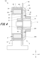
- Fig. 4 is a longitudinal sectional view of a hoist according to the second embodiment.
- Fig. 5 is a perspective view illustrating a main part of a housing in the hoist according to the second embodiment.
- a hoist 101 according to the second embodiment has the same configuration as the hoist 100 (see Fig. 2 ) according to the first embodiment.
- the hoist 101 is different from the hoist 100 in that a straightening plate 28 is provided. Therefore, here, the straightening plate 28 will be described.
- the same components of the hoist 101 as those of the hoist 100 are denoted by the same reference numerals, and the description thereof will be omitted.
- the hoist 101 includes a housing 12, the main shaft 3, the rotating body 4, the sheave 5, the plurality of stators 6, the rotor 7, and the bearing 8.
- the rotating body 4 is rotatably supported by the housing 12 via the main shaft 3 and the bearing 8.
- the housing 12 includes the shaft support portion 21, the first connection portion 22, the stator mounting portion 23, the second connection portion 24, the outer wall portion 25, and the straightening plate 28.
- the straightening plate 28 is attached to an end surface on one side of the shaft support portion 21 in the X direction and a plane on one side of the first connection portion 22.
- the straightening plate 28 is formed in a disk shape.
- a through hole 281 for avoiding interference with the main shaft 3 is provided in a central portion of the straightening plate 28.
- the center of the straightening plate 28 coincides with the center of the main shaft 3.
- the straightening plate 28 is set to a size facing the plurality of stators 6.
- the straightening plate 28 is set to a size in which the outer peripheral portion does not interfere with the rotating body 4 or the rotor 7.
- a plurality of passing holes 282 are provided in a region of the straightening plate 28 facing the plurality of stators 6.
- the air guided toward the plurality of stators 6 by the air guide portion 46 passes through the plurality of passing holes 282.
- the plurality of passing holes 282 face gaps between the plurality of stators 6. This makes it possible to efficiently direct the air guided toward the plurality of stators 6 by the air guide portion 46 to the gap between the plurality of stators 6. As a result, the plurality of stators 6 can be efficiently cooled.
- the plurality of passing holes 282 are arranged along a radial direction of the straightening plate 28. This makes it possible to cause the plurality of passing holes 282 to face the gap between the plurality of stators 6.
- the plurality of passing holes 282 are arranged along a circumferential direction of the straightening plate 28. Each of the plurality of passing holes 282 is formed in a substantially quadrangular shape. The plurality of passing holes 282 increase in size toward the outside in the radial direction. This makes it possible to increase the amount of air flowing toward the gap between the plurality of stators 6.
- the one positioned on the outermost side in the radial direction is open to the outer edge of the straightening plate 28. This makes it possible to prevent a thin plate piece which is easily damaged from being formed on the outer peripheral portion of the straightening plate 28. As a result, it is possible to increase the yield in the production of the hoist 101.
- Passing holes at the same position in the radial direction of the straightening plate 28 among the plurality of the passing holes 282 are set to have the same size. This makes it possible to unify the amount of air passing through the gap between the plurality of stators 6. As a result, unevenness can be prevented from occurring in the cooling effect of the plurality of stators 6.
- the straightening plate 28 is provided with a plurality of fins 283.
- the plurality of fins 283 are formed in a substantially quadrangular plate shape.
- the plurality of fins 283 protrude substantially perpendicularly from the side of the plurality of passing holes 282 intersecting with the radial direction of the straightening plate.
- the plurality of fins 283 protrude toward the plurality of stators 6.
- the plurality of fins 283 are formed by providing cutouts in the straightening plate 28 and bending the cutouts. When the plurality of fins 283 are formed, a plurality of passing holes 282 are formed. This makes it possible to easily form the plurality of passing holes 282 and the plurality of fins 283.
- the plurality of fins 283 guides the air that has passed through the plurality of passing holes 282 in the axial direction of the main shaft 3. This causes the air that has passed through the plurality of passing holes 282 to advance straight and pass through the gap between the plurality of stators 6. As a result, unevenness can be prevented from occurring in the air passing through the gap between the plurality of stators 6. Thus, the cooling effect can be stabilized.
- the hoist 100 of the above-described embodiment includes the housing 2 provided with the plurality of stators 6, the main shaft 3 supported by the housing 2, and the rotating body 4 supported by the main shaft 3.
- the rotating body 4 includes the sheave 5 around which the main rope 130 is wound, and the rotor 7 facing the plurality of stators 6, and the rotating body 4 rotates with respect to the housing 2.
- the rotating body 4 includes the boss portion 41 fitted to the main shaft 3, the rotating plate portion 42, the peripheral wall portion 43, and the plurality of ribs 45.
- the rotating plate portion 42 is formed in a ring shape continuous with an outer peripheral portion of the boss portion 41 and concentric with the main shaft 3.
- the peripheral wall portion 43 protrudes from the outer periphery of the rotating plate portion 42 toward the housing 2.
- the plurality of ribs 45 are provided on an inner surface that is a surface of the rotating plate portion 42 on the housing 2 side, and are radially disposed around the boss portion 41.
- the rotating plate portion 42 has the intake hole 421 for taking air from the outside to the housing 2 side.
- the housing 2 has the exhaust hole 241 disposed on the outer side with respect to the intake hole 421 in a radial direction of the main shaft 3.
- An air guide portion 46 that is a curved surface for guiding air entering the housing 2 side from the intake hole 421 to the stator 6 side is formed at a corner portion formed by the inner surface of the rotating plate portion 42 and the inner peripheral surface of the peripheral wall portion 43.
- the air taken in from the intake hole 421 moves toward the peripheral wall portion 43 because of the action of the centrifugal force.
- the air guide portion 46 can direct the air moving toward the peripheral wall portion 43 toward the stator 6. As a result, the cooling effect can be stabilized.
- the air guide portion 46 of the hoist 100 in the above-described embodiment is formed to reach a height equal to or higher than a half the height of the inner peripheral surface of the peripheral wall portion 43.
- the air guide portion 46 of the hoist 100 in the above-described embodiment is formed to reach the height of the plurality of ribs 45 or higher.
- the air guide portion 46 of the hoist 100 in the above-described embodiment is formed on the entire inner peripheral surface of the peripheral wall portion 43.
- the hoist 101 in the above-described embodiment further includes the straightening plate 28 disposed between the rotating plate portion 42 and the plurality of stators 6.
- the straightening plate 28 includes a plurality of passing holes 282 through which the air guided to the air guide portion 46 passes.
- the plurality of stators 6 of the hoist 101 in the above-described embodiment are arranged at predetermined intervals in the circumferential direction of the main shaft 3.
- the plurality of passing holes 282 of the straightening plate 28 face the gap between the plurality of stators 6.
- passing holes 282 of the straightening plate 28 of the hoist 101 are set to the same size.
- the plurality of passing holes 282 of the straightening plate 28 of the hoist 101 in the above-described embodiment are arranged in the radial direction of the main shaft 3 (straightening plate 28).
- the straightening plate 28 of the hoist 101 in the above-described embodiment includes the fins 283 protruding from the periphery of the plurality of passing holes 282 toward the plurality of stators 6.
- the elevator 1 includes the car 120, the counterweight 140 linked to the car 120 via the main rope 130, and the hoist 100 around which the main rope 130 is wound.
- the air taken in from the intake hole 421 moves toward the peripheral wall portion 43 because of the action of the centrifugal force.
- the air guide portion 46 can direct the air moving toward the peripheral wall portion 43 toward the stator 6. As a result, the cooling effect can be stabilized.
- the intake hole 421 is formed in a circular shape.
- the intake hole according to the present invention is not limited to a circular shape, but it can be formed in a rectangular shape or various other shapes.
- the size of the intake hole according to the present invention is not limited as long as the intake hole does not inhibit the generation of the differential pressure between the inner surface side and the outer surface side of the rotating body due to the centrifugal force caused by the rotation of the rotating body.
- the size of the intake hole according to the present invention is appropriately set according to the size of the exhaust hole and the like.
- the plurality of ribs 45 radially disposed around the boss portion 41 are arranged at equal angular intervals in the circumferential direction around the boss portion 41.
- the plurality of ribs according to the present invention do not have to be arranged at equal angular intervals in the circumferential direction around the boss portion 41.
- the shape and disposition of the plurality of ribs according to the present invention can be appropriately set as long as the ribs can guide air flowing from the boss portion 41 side toward the outside in the radial direction.
- the plurality of ribs 45 arranged at equal angular intervals in the circumferential direction around the boss portion 41 can make the amount of air uniform from the boss portion 41 side toward the outside in the radial direction in each air passage 47. As a result, air can efficiently flow toward the peripheral wall portion 43.
- the shape of the plurality of passing holes 282 in the straightening plate 28 is a substantially quadrangular shape.
- the shape of the plurality of passing holes in the straightening plate according to the present invention can be appropriately set to a circular shape, an elliptical shape, a polygonal shape other than a quadrangular shape, or the like.
- the plurality of fins 283 of the straightening plate 28 are formed in a substantially quadrangular plate shape.
- the shape is not limited as long as the plurality of fins of the straightening plate according to the present invention have a flat surface that guides the air that has passed through the plurality of passing holes 282 to the stator 6 side.
- the shape of the plurality of fins of the straightening plate according to the present invention can be appropriately set.
- the elevator 1 in which the machine room 160 is provided in the upper portion of the hoistway 110 has been described as an example.
- the elevator according to the present invention may be a so-called machine room-less elevator not having a machine room.
Landscapes
- Engineering & Computer Science (AREA)
- Power Engineering (AREA)
- Civil Engineering (AREA)
- Mechanical Engineering (AREA)
- Structural Engineering (AREA)
- Cage And Drive Apparatuses For Elevators (AREA)
Abstract
Description
- The present invention relates to a hoist and an elevator.
- A hoist for an elevator has been required to be downsized in recent years. A downsized hoist reduces the heat dissipation area of a motor. On the other hand, a hoist with an improved output increases the amount of heat generation. Thus, a downsized hoist causes a problem in stabilizing motor performance. Accordingly, a hoist that sends cooling air between a rotor and a stator is considered (see Patent Literature 1). The hoist described in
Patent Literature 1 includes a blower blade on an end surface of a rotor. This causes the wind traveling in a rotation axis direction of the rotor with the rotation of the rotor to flow between the rotor and the stator. - Patent Literature 1:
JP 2016-220370 A - However, in the hoist described in
Patent Literature 1, the cooling air that has passed through the rotor travels substantially perpendicularly to an inner wall plane of a housing. This causes the cooling air that has passed through the rotor to stagnate in the closed space inside the housing. As a result, there arises a problem that the cooling air does not flow efficiently and the cooling effect is not stable. - It is conceivable to provide a through hole for cooling air on the inner wall plane of the housing. However, the cooling air that has flowed through the rotor on the rotating body side passes through the through hole in the housing on the stationary portion side. Thus, the cooling air does not flow efficiently.
- An object of the present invention is to provide a hoist and an elevator capable of stabilizing a cooling effect in consideration of the above problems.
- To solve the above problems and achieve the object, a hoist includes a housing provided with a plurality of stators, a main shaft supported by the housing, and a rotating body supported by the main shaft. The rotating body includes a sheave around which a main rope is wound and a rotor facing the plurality of stators, and the rotating body rotates with respect to the housing. The rotating body has a boss portion fitted to the main shaft, a rotating plate portion, a peripheral wall portion, and a plurality of ribs. The rotating plate portion is formed in a ring shape continuous with an outer peripheral portion of the boss portion and concentric with the main shaft. The peripheral wall portion protrudes from the outer periphery of the rotating plate portion toward the housing. The plurality of ribs are provided on an inner surface that is a surface of the rotating plate portion on the housing side, and are radially disposed around the boss portion. The rotating plate portion has an intake hole for taking air from the outside to the housing side. The housing has an exhaust hole located outside the intake hole in the radial direction of the main shaft. An air guide portion that is a curved surface for guiding air entering the housing side from the intake hole to the stator side is formed at a corner portion formed by an inner surface of the rotating plate portion and an inner peripheral surface of the peripheral wall portion.
- An elevator includes a car, a counterweight linked to the car via a main rope, and the hoist around which the main rope is wound.
- The hoist and the elevator having the above configuration can stabilize the cooling effect.
- Problems, configurations, and effects other than those described above will be clarified by the following description of embodiments.
-
-
Fig. 1 is an overall configuration diagram of an elevator according to a first embodiment. -
Fig. 2 is a longitudinal sectional view of a hoist according to the first embodiment. -
Fig. 3 is a perspective view illustrating a main part of a rotating body in the hoist according to the first embodiment. -
Fig. 4 is a longitudinal sectional view of a hoist according to a second embodiment. -
Fig. 5 is a perspective view illustrating a main part of a housing in the hoist according to the second embodiment. - Hereinafter, embodiments of the present invention will be described in detail with reference to the drawings. In the present specification and the drawings, elements having substantially the same function or configuration are denoted by the same reference numerals, and redundant description is omitted.
- First, a configuration of an elevator according to a first embodiment of the present invention will be described with reference to
Fig. 1 . -
Fig. 1 is an overall configuration diagram of an elevator according to the first embodiment. - As illustrated in
Fig. 1 , anelevator 1 is installed in ahoistway 110 formed in a building structure. Theelevator 1 includes acar 120 on which people and luggage are to be loaded, amain rope 130, acounterweight 140, and ahoist 100. Amachine room 160 is provided at the top of thehoistway 110. - The
hoist 100 is disposed in themachine room 160. Themain rope 130 is wound around thehoist 100. Thehoist 100 is a device that winds up themain rope 130 to raise and lower thecar 120. Adiverting pulley 150 is provided near thehoist 100. Themain rope 130 is loaded on thediverting pulley 150. - The
car 120 is formed in a substantially hollow rectangular parallelepiped shape. Thecar 120 is linked to thecounterweight 140 via themain rope 130. When thehoist 100 winds up themain rope 130, thecar 120 and thecounterweight 140 lift and lower in opposite directions. - The mass of the
counterweight 140 is set to be substantially the same as the mass of thecar 120 with no load. Thus, when thecar 120 is with no load, the tension ratio between themain rope 130 on thecar 120 side and themain rope 130 on thecounterweight 140 side is 1. This makes it possible to suppress the output of thehoist 100 at the time of no load. - Next, a configuration of the
hoist 100 will be described with reference toFigs. 2 and3 . -
Fig. 2 is a longitudinal sectional view of thehoist 100.Fig. 3 is a perspective view illustrating a main part of a rotating body in thehoist 100. - As illustrated in
Fig. 2 , the hoist 100 includes ahousing 2, amain shaft 3, arotating body 4, asheave 5, a plurality ofstators 6, arotor 7, and abearing 8. Therotating body 4 is rotatably supported by thehousing 2 via themain shaft 3 and thebearing 8. The plurality ofstator 6 disposed in an annular shape are attached to thehousing 2. Therotor 7 having an annular shape is attached to therotating body 4. Therotor 7 is disposed on the outer side with respect to the plurality ofstators 6 in a radial direction. That is, the hoist 100 is an outer rotor type hoist. - In the following description, an axial direction of the
main shaft 3 is referred to as an X direction. A vertical direction with respect to the axial direction of themain shaft 3 and a lifting and lowering direction of thecar 120 is defined as a Y direction. A direction orthogonal to the X direction and the Y direction is defined as a Z direction. Thehousing 2 and therotating body 4 face each other in the X direction. Further, in the X direction, therotating body 4 side is defined as one side. In the X direction, thehousing 2 side is defined as the other side. - As illustrated in
Fig. 2 , thehousing 2 is supported by asupport base 9. Thesupport base 9 is fixed to the machine room 160 (seeFig. 1 ) provided in an upper portion of thehoistway 110. Thehousing 2 faces therotating body 4 in the X direction. - The
housing 2 includes ashaft support portion 21 that rotatably supports themain shaft 3 via thebearing 8, astator mounting portion 23 to which the plurality ofstators 6 are attached, and afirst connection portion 22 that connects theshaft support portion 21 and thestator mounting portion 23. Thehousing 2 includes anouter wall portion 25 covering an outer peripheral portion of therotating body 4, and asecond connection portion 24 connecting thestator mounting portion 23 and theouter wall portion 25. - The
shaft support portion 21 is positioned at a substantially central portion on the YZ plane of thehousing 2. Theshaft support portion 21 is formed in a cylindrical shape with the X direction as an axial direction. Thestator mounting portion 23 is formed in a cylindrical shape with the X direction as an axial direction. An inner diameter of thestator mounting portion 23 is larger than an outer diameter of theshaft support portion 21. Thestator mounting portion 23 is positioned on the outer side with respect to theshaft support portion 21 in a radial direction. - The
first connection portion 22 is formed of an annular plate body. The plane of thefirst connection portion 22 is substantially orthogonal to the X direction. The inner peripheral side of thefirst connection portion 22 is continuous with an end portion on one side of theshaft support portion 21 in the X direction. The outer peripheral side of thefirst connection portion 22 is continuous with an end portion on one side of thestator mounting portion 23 in the X direction. - The
outer wall portion 25 is formed in a cylindrical shape with the X direction as an axial direction. An inner diameter of theouter wall portion 25 is larger than an outer diameter of thestator mounting portion 23. Theouter wall portion 25 is positioned on the outer side with respect to thestator mounting portion 23 in a radial direction. The inner peripheral portion of theouter wall portion 25 and the outer peripheral portion of thestator mounting portion 23 face each other with a predetermined distance therebetween in the radial direction. The plurality ofstators 6 and therotor 7 are disposed in a space between theouter wall portion 25 and thestator mounting portion 23. - The
second connection portion 24 is formed of an annular plate body. The plane of thesecond connection portion 24 is substantially orthogonal to the X direction. The inner peripheral side of thesecond connection portion 24 is continuous with an end portion on the other side of thestator mounting portion 23 in the X direction. The outer peripheral side of thesecond connection portion 24 is continuous with an end portion on the other side of theouter wall portion 25 in the X direction. A plurality ofexhaust holes 241 are formed in thesecond connection portion 24. The plurality ofexhaust holes 241 face a gap between the plurality ofstators 6. - The
main shaft 3 is formed in a columnar shape with the X direction as an axial direction. The other side of themain shaft 3 in the X direction is rotatably supported by thehousing 2 via thebearing 8. Therotating body 4 is fitted to one side of themain shaft 3 in the X direction. - The
bearing 8 is attached to an inner peripheral portion of theshaft support portion 21. Thebearing 8 is formed in an annular shape. Therotating body 4 engages with thebearing 8. Therotating body 4 is rotatably supported by themain shaft 3 via thebearing 8. - The
rotating body 4 includes aboss portion 41 fitted to one side of themain shaft 3, arotating plate portion 42 continuous with an outer peripheral portion of theboss portion 41, aperipheral wall portion 43 protruding from the outer peripheral portion of therotating plate portion 42 toward thehousing 2, and aflange portion 44 continuous with theperipheral wall portion 43. - The
boss portion 41 is provided at a substantially central portion on the YZ plane of therotating body 4. Theboss portion 41 is formed in a cylindrical shape with the X direction as an axial direction. Thesheave 5 is attached to an outer peripheral portion of theboss portion 41. - The
rotating plate portion 42 is continuous with an intermediate portion of theboss portion 41 in the X direction. Therotating plate portion 42 is formed in a ring shape concentric with the boss portion 41 (main shaft 3). The surface of therotating plate portion 42 facing one side in the X direction is an outer surface facing the outside of the hoist 100. On the other hand, the surface of therotating plate portion 42 facing the other side in the X direction is an inner surface facing the inside of the hoist 100 (housing 2 side). The end surface of thesheave 5 on the other side in the X direction abuts on the outer surface of therotating plate portion 42. - The
rotating plate portion 42 is provided with a plurality of intake holes 421. The plurality ofintake holes 421 are arranged along a circumferential direction of the main shaft 3 (rotating plate portion 42). In the radial direction of themain shaft 3, the plurality ofintake holes 421 are disposed closer to themain shaft 3 than the plurality ofexhaust holes 241 of thehousing 2. In other words, in the radial direction of themain shaft 3, the plurality ofexhaust holes 241 are disposed on the outer side with respect to the plurality of intake holes 421. The plurality ofintake holes 421 take air from the outside of the hoist 100 into the inside of the hoist 100 (housing 2 side). - A plurality of
ribs 45 are formed on the inner surface of therotating plate portion 42. The plurality ofribs 45 are radially disposed around the boss portion 41 (seeFig. 3 ). The plurality ofribs 45 are arranged at equal angular intervals in the circumferential direction around theboss portion 41. The plurality ofribs 45 extend in the radial direction of therotating plate portion 42. One end of eachrib 45 is continuous with theboss portion 41. The other end of eachrib 45 is continuous with the inner peripheral surface of theperipheral wall portion 43. - The height of the plurality of ribs 45 (the height from the inner surface of the rotating plate portion) is lower than the height of the inner peripheral surface of the
peripheral wall portion 43. The height of the plurality ofribs 45 is higher than a half of the height of the inner peripheral surface of theperipheral wall portion 43. The plurality ofintake holes 421 described above is formed one by one between theribs 45 adjacent in the circumferential direction. - The
peripheral wall portion 43 is formed in a cylindrical shape with the X direction as an axial direction. The inner diameter of theperipheral wall portion 43 is larger than the outer diameter of theboss portion 41. Theperipheral wall portion 43 is positioned on the outer side with respect to theboss portion 41 in the radial direction (seeFig. 2 ). An end portion on one side of theperipheral wall portion 43 in the X direction is continuous with the inner surface of therotating plate portion 42. - A
rotor fixing groove 431 for attaching therotor 7 is provided on the end surface on the other side of theperipheral wall portion 43 in the X direction. Therotor fixing groove 431 is formed in an annular shape along the circumferential direction of theperipheral wall portion 43. Therotor 7 fits into therotor fixing groove 431. - The
flange portion 44 is formed of a plate body protruding outward in the radial direction of themain shaft 3 from the end portion on the other side of theperipheral wall portion 43 in the X direction. Theflange portion 44 faces a gap between thestator 6 attached to thehousing 2 and therotor 7 attached to theperipheral wall portion 43 in the X direction. Thus, when viewed from one side in the X direction, the gap between thestator 6 and therotor 7 is covered by theflange portion 44. - As illustrated in
Fig. 3 , a plurality of spaces surrounded by theribs 45, theboss portion 41, and theperipheral wall portion 43 are formed on the inner surface side of therotating plate portion 42. The plurality of spaces areair passages 47 through which air taken in from the plurality ofintake holes 421 passes. - An
air guide portion 46 is formed at a corner portion formed by the inner surface of therotating plate portion 42 and the inner peripheral surface of theperipheral wall portion 43. Theair guide portion 46 is a curved surface for guiding the air entering the inner side of the hoist 100 (housing 2 side) from the plurality ofintake holes 421 and passing through theair passage 47 to thestator 6 side. Theair guide portion 46 is formed up to the height of therib 45. - The
air guide portion 46 is formed axially symmetrically with respect to a center line of theboss portion 41. Theair guide portion 46 smoothly continues to the inner surface of therotating plate portion 42 and the inner peripheral surface of theperipheral wall portion 43. The shape of a longitudinal section (section parallel to the XY plane) of theair guide portion 46 is formed in, for example, an arc. In this case, the central angle of the arc is set within 90 degrees. The shape of the longitudinal section of theair guide portion 46 is not limited to an arc, and it may be a curved surface whose curvature is gradually changed. - The height of the
air guide portion 46 may be equal to or higher than a half of the height of the inner peripheral surface of theperipheral wall portion 43. This makes it possible to efficiently direct the air passing through theair passage 47 toward thestator 6. Then, the air in theair passage 47 can be prevented from stagnating. For the efficiency of guiding the air to thestator 6 side and reducing the stagnation of the air, theair guide portion 46 is preferably formed on the entire inner peripheral surface of theperipheral wall portion 43. - The
sheave 5 is formed in a cylindrical shape with the X direction as an axial direction. Thesheave 5 is fitted to an outer peripheral portion on one side of theboss portion 41 in the X direction. The end surface on the other side of thesheave 5 in the X direction abuts on the outer surface of therotating plate portion 42. The plurality ofintake holes 421 of therotating plate portion 42 are provided at positions not overlapping with thesheave 5 when viewed from the X direction. - The end surface on one side of the
sheave 5 in the X direction forms the same plane as the end surface on one side of theboss portion 41 in the X direction. A plurality of grooves around which themain rope 130 is wound are formed on an outer peripheral surface of thesheave 5. Thesheave 5 rotates together with theboss portion 41. - The plurality of
stators 6 are attached to an outer peripheral portion of thestator mounting portion 23 in thehousing 2. The plurality ofstators 6 are arranged at predetermined intervals along the circumferential direction of the stator mounting portion 23 (main shaft 3). Eachstator 6 includes an iron core and a coil wound around the iron core. - As described above, the plurality of
exhaust holes 241 provided in thehousing 2 face the gap between the plurality ofstators 6. Thus, the air that has entered the inner side of the hoist 100 from theintake hole 421 of therotating body 4 is exhausted to the outside of the hoist 100 from the plurality ofexhaust holes 241 mainly through the gap between the plurality ofstators 6. - The
rotor 7 is fixed to therotor fixing groove 431 of theperipheral wall portion 43. Therotor 7 is formed in a cylindrical shape with the X direction as an axial direction. Therotor 7 is a magnetic body. Therotor 7 faces the plurality ofstators 6 with an air gap interposed therebetween in the radial direction of the stator mounting portion 23 (main shaft 3). - The plurality of
intake holes 421 provided in therotating body 4 are holes for taking air from the outer surface side to the inner surface side of therotating plate portion 42. Each of the plurality ofintake holes 421 is formed in a circular shape. The plurality ofintake holes 421 are disposed on the circumference of a circle having a first radius R1 about the rotation axis of themain shaft 3. The plurality ofintake holes 421 are disposed one by one between theribs 45 adjacent to each other in the circumferential direction of themain shaft 3. - Each
intake hole 421 is positioned on theboss portion 41 side in theair passage 47 described above. The distance R1 from the center of themain shaft 3 to theintake hole 421 is shorter than a distance R2 from the center of themain shaft 3 to theexhaust hole 241. The plurality ofintake holes 421 do not overlap with the plurality ofexhaust holes 241 when viewed from the axial direction of themain shaft 3. - The plurality of
exhaust holes 241 provided in thehousing 2 are holes for exhausting air to the opposite side of thehousing 2 from therotating body 4. The plurality ofexhaust holes 241 are disposed on the circumference of a circle having a second radius R2 about the rotation axis of themain shaft 3. The plurality ofexhaust holes 241 face the gap between the plurality ofstators 6. The distance R2 from the center of themain shaft 3 to theexhaust hole 241 is larger than the distance R1 from the center of themain shaft 3 to theintake hole 421. - The shapes of the plurality of
exhaust holes 241 are not particularly limited. The plurality ofexhaust holes 241 may be formed in, for example, a rectangular slit shape or formed to have a circular diameter similar to that of theintake hole 421. The plurality ofexhaust holes 241 may have the same shape as the shape of the gap between the plurality ofstators 6. - In the hoist 100 having such a configuration, when the
rotating body 4 rotates, air outside the hoist 100 is sucked from the plurality of intake holes 421. Then, the air sucked from the plurality ofintake holes 421 passes through the inside of the hoist 100 and is exhausted from the plurality of exhaust holes 241. With this configuration, the plurality ofstators 6 and the like of the hoist 100 are cooled. - Next, a cooling action of the hoist 100 will be described. When the
rotating body 4 rotates, a centrifugal force acts on the air in theair passage 47 on the inner surface side of therotating plate portion 42. This causes air to move from theboss portion 41 side toward theperipheral wall portion 43 in theair passage 47. This movement of air occurs along the extending direction of the plurality ofribs 45. - When air moves in the
air passage 47, the pressure on theboss portion 41 side decreases in theair passage 47. This generates a difference in air pressure between the outer surface side and the inner surface side of therotating plate portion 42. That is, the air pressure in the vicinity of the plurality ofintake holes 421 on the inner surface side of therotating plate portion 42 becomes a negative pressure with respect to the air pressure on the outer surface side of therotating plate portion 42. As a result, air is sucked into the hoist 100 from the plurality of intake holes 421. - On the other hand, the air flowing in the direction away from the
boss portion 41 in theair passage 47 is guided by theair guide portion 46 to thehousing 2 side (plurality ofstators 6 side). As a result, the air flowing through theair passage 47 passes between therotor 7 and the plurality ofstators 6 or between theadjacent stators 6, and flows to thesecond connection portion 24 side of thehousing 2. - Then, in the vicinity of the plurality of
exhaust holes 241 of thesecond connection portion 24, air flows in from therotating body 4 side, whereby the air pressure increases. This generates a difference in air pressure between the outer surface side and the inner surface side of thesecond connection portion 24. That is, when therotating body 4 rotates, the air pressure in the vicinity of the plurality of exhaust holes 241 on the inner surface side of thesecond connection portion 24 becomes a positive pressure with respect to the air pressure on the outer surface side of thesecond connection portion 24. As a result, the air in the hoist 100 is exhausted from the plurality of exhaust holes 241. - In this manner, in the present embodiment, with the rotation of the
rotating body 4, the pressure in the vicinity of the plurality ofintake holes 421 of therotating plate portion 42 becomes a negative pressure with respect to the outside air, and the pressure in the vicinity of the plurality ofexhaust holes 241 of thehousing 2 becomes a positive pressure with respect to the outside air. Thus, while therotating body 4 is rotating, cooling air can always flow into the hoist 100. - The pressure distribution of the air in the vicinity of the plurality of
intake holes 421 and in the vicinity of the plurality of exhaust holes 241 does not depend on the rotation direction of therotating body 4. That is, the same pressure distribution occurs regardless of whether the rotation direction of therotating body 4 is clockwise or counterclockwise. Thus, the hoist 100 can cause stable cooling air to flow inside regardless of the rotation direction of therotating body 4. - In the present embodiment, the
air guide portion 46 is provided at the corner portion formed by the inner surface of therotating plate portion 42 and the inner peripheral surface of theperipheral wall portion 43. This makes it possible to efficiently direct the air moving toward theperipheral wall portion 43 because of the action of the centrifugal force toward thehousing 2. Further, the air can be prevented from stagnating in theair passage 47. As a result, the cooling effect can be stabilized. - In the present embodiment, the plurality of
exhaust holes 241 face the gap between theadjacent stators 6. This makes it possible to efficiently exhaust the air heated by flowing between theadjacent stators 6. As a result, the cooling effect of thestator 6 can be enhanced. - In the present embodiment, the plurality of
ribs 45 are arranged at equal angular intervals in the circumferential direction around theboss portion 41. This causes the amount of air flowing through eachair passage 47 to be equal. As a result, air can uniformly flow from theboss portion 41 side to theperipheral wall portion 43 side. Thus, the plurality ofstators 6 can be uniformly cooled. - Next, a hoist according to a second embodiment of the present invention will be described with reference to
Figs. 4 and5 . -
Fig. 4 is a longitudinal sectional view of a hoist according to the second embodiment.Fig. 5 is a perspective view illustrating a main part of a housing in the hoist according to the second embodiment. - As illustrated in
Fig. 4 , a hoist 101 according to the second embodiment has the same configuration as the hoist 100 (seeFig. 2 ) according to the first embodiment. The hoist 101 is different from the hoist 100 in that a straighteningplate 28 is provided. Therefore, here, the straighteningplate 28 will be described. The same components of the hoist 101 as those of the hoist 100 are denoted by the same reference numerals, and the description thereof will be omitted. - The hoist 101 includes a
housing 12, themain shaft 3, therotating body 4, thesheave 5, the plurality ofstators 6, therotor 7, and thebearing 8. Therotating body 4 is rotatably supported by thehousing 12 via themain shaft 3 and thebearing 8. - As illustrated in
Fig. 4 , thehousing 12 includes theshaft support portion 21, thefirst connection portion 22, thestator mounting portion 23, thesecond connection portion 24, theouter wall portion 25, and the straighteningplate 28. The straighteningplate 28 is attached to an end surface on one side of theshaft support portion 21 in the X direction and a plane on one side of thefirst connection portion 22. - The straightening
plate 28 is formed in a disk shape. A throughhole 281 for avoiding interference with themain shaft 3 is provided in a central portion of the straighteningplate 28. The center of the straighteningplate 28 coincides with the center of themain shaft 3. The straighteningplate 28 is set to a size facing the plurality ofstators 6. The straighteningplate 28 is set to a size in which the outer peripheral portion does not interfere with therotating body 4 or therotor 7. - As illustrated in
Fig. 5 , a plurality of passingholes 282 are provided in a region of the straighteningplate 28 facing the plurality ofstators 6. The air guided toward the plurality ofstators 6 by theair guide portion 46 passes through the plurality of passingholes 282. The plurality of passingholes 282 face gaps between the plurality ofstators 6. This makes it possible to efficiently direct the air guided toward the plurality ofstators 6 by theair guide portion 46 to the gap between the plurality ofstators 6. As a result, the plurality ofstators 6 can be efficiently cooled. - The plurality of passing
holes 282 are arranged along a radial direction of the straighteningplate 28. This makes it possible to cause the plurality of passingholes 282 to face the gap between the plurality ofstators 6. The plurality of passingholes 282 are arranged along a circumferential direction of the straighteningplate 28. Each of the plurality of passingholes 282 is formed in a substantially quadrangular shape. The plurality of passingholes 282 increase in size toward the outside in the radial direction. This makes it possible to increase the amount of air flowing toward the gap between the plurality ofstators 6. - Out of the plurality of passing
holes 282, the one positioned on the outermost side in the radial direction is open to the outer edge of the straighteningplate 28. This makes it possible to prevent a thin plate piece which is easily damaged from being formed on the outer peripheral portion of the straighteningplate 28. As a result, it is possible to increase the yield in the production of the hoist 101. - Passing holes at the same position in the radial direction of the straightening
plate 28 among the plurality of the passingholes 282 are set to have the same size. This makes it possible to unify the amount of air passing through the gap between the plurality ofstators 6. As a result, unevenness can be prevented from occurring in the cooling effect of the plurality ofstators 6. - The straightening
plate 28 is provided with a plurality offins 283. The plurality offins 283 are formed in a substantially quadrangular plate shape. The plurality offins 283 protrude substantially perpendicularly from the side of the plurality of passingholes 282 intersecting with the radial direction of the straightening plate. The plurality offins 283 protrude toward the plurality ofstators 6. - The plurality of
fins 283 are formed by providing cutouts in the straighteningplate 28 and bending the cutouts. When the plurality offins 283 are formed, a plurality of passingholes 282 are formed. This makes it possible to easily form the plurality of passingholes 282 and the plurality offins 283. - The plurality of
fins 283 guides the air that has passed through the plurality of passingholes 282 in the axial direction of themain shaft 3. This causes the air that has passed through the plurality of passingholes 282 to advance straight and pass through the gap between the plurality ofstators 6. As a result, unevenness can be prevented from occurring in the air passing through the gap between the plurality ofstators 6. Thus, the cooling effect can be stabilized. - As described above, the hoist 100 of the above-described embodiment includes the
housing 2 provided with the plurality ofstators 6, themain shaft 3 supported by thehousing 2, and therotating body 4 supported by themain shaft 3. Therotating body 4 includes thesheave 5 around which themain rope 130 is wound, and therotor 7 facing the plurality ofstators 6, and therotating body 4 rotates with respect to thehousing 2. Therotating body 4 includes theboss portion 41 fitted to themain shaft 3, therotating plate portion 42, theperipheral wall portion 43, and the plurality ofribs 45. Therotating plate portion 42 is formed in a ring shape continuous with an outer peripheral portion of theboss portion 41 and concentric with themain shaft 3. Theperipheral wall portion 43 protrudes from the outer periphery of therotating plate portion 42 toward thehousing 2. The plurality ofribs 45 are provided on an inner surface that is a surface of therotating plate portion 42 on thehousing 2 side, and are radially disposed around theboss portion 41. Therotating plate portion 42 has theintake hole 421 for taking air from the outside to thehousing 2 side. Thehousing 2 has theexhaust hole 241 disposed on the outer side with respect to theintake hole 421 in a radial direction of themain shaft 3. Anair guide portion 46 that is a curved surface for guiding air entering thehousing 2 side from theintake hole 421 to thestator 6 side is formed at a corner portion formed by the inner surface of therotating plate portion 42 and the inner peripheral surface of theperipheral wall portion 43. - With this configuration, when the
rotating body 4 rotates, the air taken in from theintake hole 421 moves toward theperipheral wall portion 43 because of the action of the centrifugal force. Theair guide portion 46 can direct the air moving toward theperipheral wall portion 43 toward thestator 6. As a result, the cooling effect can be stabilized. - The
air guide portion 46 of the hoist 100 in the above-described embodiment is formed to reach a height equal to or higher than a half the height of the inner peripheral surface of theperipheral wall portion 43. - This makes it possible to efficiently direct the air moving toward the
peripheral wall portion 43 toward thestator 6. - The
air guide portion 46 of the hoist 100 in the above-described embodiment is formed to reach the height of the plurality ofribs 45 or higher. - This makes it possible to efficiently direct the air moving toward the
peripheral wall portion 43 along the plurality ofribs 45 toward thestator 6. - The
air guide portion 46 of the hoist 100 in the above-described embodiment is formed on the entire inner peripheral surface of theperipheral wall portion 43. - This makes it possible to efficiently direct the air moving toward the
peripheral wall portion 43 toward thestator 6. - The hoist 101 in the above-described embodiment further includes the straightening
plate 28 disposed between therotating plate portion 42 and the plurality ofstators 6. The straighteningplate 28 includes a plurality of passingholes 282 through which the air guided to theair guide portion 46 passes. - This makes it possible to direct the air guided toward the plurality of
stators 6 by theair guide portion 46 to a predetermined portion related to the plurality ofstators 6. - The plurality of
stators 6 of the hoist 101 in the above-described embodiment are arranged at predetermined intervals in the circumferential direction of themain shaft 3. The plurality of passingholes 282 of the straighteningplate 28 face the gap between the plurality ofstators 6. - This makes it possible to efficiently direct the air guided toward the plurality of
stators 6 by theair guide portion 46 to the gap between the plurality ofstators 6. As a result, the plurality ofstators 6 can be efficiently cooled. - Among the plurality of passing
holes 282 of the straighteningplate 28 of the hoist 101 in the above-described embodiment, passingholes 282 at the same position in the radial direction of the main shaft 3 (straightening plate 28) are set to the same size. - This makes it possible to unify the amount of air passing through the gap between the plurality of
stators 6. As a result, unevenness can be prevented from occurring in the cooling effect of the plurality ofstators 6. - The plurality of passing
holes 282 of the straighteningplate 28 of the hoist 101 in the above-described embodiment are arranged in the radial direction of the main shaft 3 (straightening plate 28). - This makes it possible to cause the plurality of passing
holes 282 to face the gap between the plurality ofstators 6. - The straightening
plate 28 of the hoist 101 in the above-described embodiment includes thefins 283 protruding from the periphery of the plurality of passingholes 282 toward the plurality ofstators 6. - This makes it possible to guide the traveling direction of the air that has passed through the plurality of passing
holes 282. That is, the air that has passed through the plurality of passingholes 282 advances straight and passes through the gap between the plurality ofstators 6. As a result, unevenness can be prevented from occurring in the air passing through the gap between the plurality ofstators 6. - The
elevator 1 according to the above-described embodiment includes thecar 120, thecounterweight 140 linked to thecar 120 via themain rope 130, and the hoist 100 around which themain rope 130 is wound. - With this configuration, when the
rotating body 4 of the hoist 100 rotates, the air taken in from theintake hole 421 moves toward theperipheral wall portion 43 because of the action of the centrifugal force. Theair guide portion 46 can direct the air moving toward theperipheral wall portion 43 toward thestator 6. As a result, the cooling effect can be stabilized. - The hoist and the elevator of the present invention have been described above including the function effect thereof. However, the hoist and the elevator of the present invention are not limited to the above-described embodiments, and various modifications can be made without departing from the gist of the invention described in the claims.
- In the above-described embodiment, the
intake hole 421 is formed in a circular shape. However, the intake hole according to the present invention is not limited to a circular shape, but it can be formed in a rectangular shape or various other shapes. The size of the intake hole according to the present invention is not limited as long as the intake hole does not inhibit the generation of the differential pressure between the inner surface side and the outer surface side of the rotating body due to the centrifugal force caused by the rotation of the rotating body. The size of the intake hole according to the present invention is appropriately set according to the size of the exhaust hole and the like. - In the above-described embodiment, the plurality of
ribs 45 radially disposed around theboss portion 41 are arranged at equal angular intervals in the circumferential direction around theboss portion 41. However, the plurality of ribs according to the present invention do not have to be arranged at equal angular intervals in the circumferential direction around theboss portion 41. The shape and disposition of the plurality of ribs according to the present invention can be appropriately set as long as the ribs can guide air flowing from theboss portion 41 side toward the outside in the radial direction. The plurality ofribs 45 arranged at equal angular intervals in the circumferential direction around theboss portion 41 can make the amount of air uniform from theboss portion 41 side toward the outside in the radial direction in eachair passage 47. As a result, air can efficiently flow toward theperipheral wall portion 43. - In the embodiments described above, the shape of the plurality of passing
holes 282 in the straighteningplate 28 is a substantially quadrangular shape. However, the shape of the plurality of passing holes in the straightening plate according to the present invention can be appropriately set to a circular shape, an elliptical shape, a polygonal shape other than a quadrangular shape, or the like. - In the embodiments described above, the plurality of
fins 283 of the straighteningplate 28 are formed in a substantially quadrangular plate shape. However, the shape is not limited as long as the plurality of fins of the straightening plate according to the present invention have a flat surface that guides the air that has passed through the plurality of passingholes 282 to thestator 6 side. Thus, the shape of the plurality of fins of the straightening plate according to the present invention can be appropriately set. - In the embodiments described above, the
elevator 1 in which themachine room 160 is provided in the upper portion of thehoistway 110 has been described as an example. However, the elevator according to the present invention may be a so-called machine room-less elevator not having a machine room. - The embodiments described above have been described in detail in order to clearly describe the present invention, and are not necessarily limited to those having all the described configurations. It is possible to add, delete, and replace other configurations for a part of the configuration of the embodiments.
- In the present specification, words such as "parallel" and "orthogonal" are used, but these do not strictly mean only "parallel" and "orthogonal", but they may mean a state of "substantially parallel" or "substantially orthogonal" including "parallel" and "orthogonal" and in a range in which the function can be exhibited.
-
- 1
- elevator
- 2, 12
- housing
- 3
- main shaft
- 4
- rotating body
- 5
- sheave
- 6
- stator
- 7
- rotor
- 8
- bearing
- 9
- support base
- 21
- shaft support portion
- 22
- first connection portion
- 23
- stator mounting portion
- 24
- second connection portion
- 25
- outer wall portion
- 28
- straightening plate
- 41
- boss portion
- 42
- rotating plate portion
- 43
- peripheral wall portion
- 44
- flange portion
- 45
- rib
- 46
- air guide portion
- 47
- air passage
- 100, 101
- hoist
- 110
- hoistway
- 130
- main rope
- 150
- diverting pulley
- 160
- machine room
- 241
- exhaust hole
- 281
- through hole
- 282
- passing hole
- 283
- fin
- 421
- intake hole
- 431
- rotor fixing groove
Claims (10)
- A hoist comprising:a housing provided with a plurality of stators;a main shaft supported by the housing; anda rotating body supported by the main shaft, the rotating body including a sheave around which a main rope is wound and a rotor facing the plurality of stators, the rotating body rotating with respect to the housing, whereinthe rotating body includes:a boss portion that fits to the main shaft; a rotating plate portion continuous with an outer peripheral portion of the boss portion and formed in a ring shape concentric with the main shaft; a peripheral wall portion protruding from an outer periphery of the rotating plate portion toward the housing; and a plurality of ribs provided on an inner surface that is a surface of the rotating plate portion on the housing side, the plurality of ribs being radially disposed around the boss portion,the rotating plate portion includes an intake hole through which air is taken from an outside toward the housing,the housing includes an exhaust hole disposed on an outer side with respect to the intake hole in a radial direction of the main shaft, andan air guide portion that is a curved surface for guiding air entering the housing side from the intake hole to the stator side is formed at a corner portion formed by an inner surface of the rotating plate portion and an inner peripheral surface of the peripheral wall portion.
- The hoist according to claim 1, wherein
the air guide portion is formed to reach a height equal to or higher than a half of a height of an inner peripheral surface of the peripheral wall portion. - The hoist according to claim 1, wherein
the air guide portion is formed to reach a height equal to or higher than a height of the plurality of ribs. - The hoist according to claim 1, wherein
the air guide portion is formed on an entire inner peripheral surface of the peripheral wall portion. - The hoist according to claim 1, further comprising
a straightening plate disposed between the rotating plate portion and the plurality of stators and including a plurality of passing holes through which air guided to the air guide portion passes. - The hoist according to claim 5, whereinthe plurality of stators are arranged at predetermined intervals in a circumferential direction of the main shaft, andthe plurality of passing holes of the straightening plate face a gap between the plurality of stators.
- The hoist according to claim 6, wherein
passing holes at a same position in the radial direction of the main shaft among the plurality of passing holes are set to have a same size. - The hoist according to claim 6, wherein
the plurality of passing holes are arranged in the radial direction of the main shaft. - The hoist according to claim 5, wherein
the straightening plate includes a fin protruding from a periphery of the plurality of passing holes toward the plurality of stators. - An elevator comprising:a car;a counterweight linked to the car via a main rope; anda hoist around which the main rope is wound, whereinthe hoist includes:a housing provided with a plurality of stators;a main shaft supported by the housing; anda rotating body supported by the main shaft, the rotating body including a sheave around which the main rope is wound and a rotor facing the stators, the rotating body rotating with respect to the housing,the rotating body includes:a boss portion that fits to the main shaft; a rotating plate portion continuous with an outer peripheral portion of the boss portion and formed in a ring shape concentric with the main shaft; a peripheral wall portion protruding from an outer periphery of the rotating plate portion toward the housing; and a plurality of ribs provided on an inner surface that is a surface of the rotating plate portion on the housing side, the plurality of ribs being radially disposed around the boss portion,the rotating plate portion includes an intake hole through which air is taken from an outside toward the housing,the housing includes an exhaust hole disposed on an outer side with respect to the intake hole in a radial direction of the main shaft, andan air guide portion that is a curved surface for guiding air entering the housing side from the intake hole to the stator side is formed at a corner portion formed by an inner surface of the rotating plate portion and an inner peripheral surface of the peripheral wall portion.
Applications Claiming Priority (1)
| Application Number | Priority Date | Filing Date | Title |
|---|---|---|---|
| PCT/JP2022/012556 WO2023175882A1 (en) | 2022-03-18 | 2022-03-18 | Hoist and elevator |
Publications (2)
| Publication Number | Publication Date |
|---|---|
| EP4495043A1 true EP4495043A1 (en) | 2025-01-22 |
| EP4495043A4 EP4495043A4 (en) | 2026-01-21 |
Family
ID=88022929
Family Applications (1)
| Application Number | Title | Priority Date | Filing Date |
|---|---|---|---|
| EP22932155.9A Pending EP4495043A4 (en) | 2022-03-18 | 2022-03-18 | WINCHES AND LIFT |
Country Status (4)
| Country | Link |
|---|---|
| EP (1) | EP4495043A4 (en) |
| JP (1) | JP7673320B2 (en) |
| CN (1) | CN118574783A (en) |
| WO (1) | WO2023175882A1 (en) |
Family Cites Families (8)
| Publication number | Priority date | Publication date | Assignee | Title |
|---|---|---|---|---|
| JPH09117101A (en) * | 1995-10-13 | 1997-05-02 | Toshiba Corp | Rotating electric machine |
| JP3583884B2 (en) * | 1997-01-31 | 2004-11-04 | 東芝テック株式会社 | Rotating electric machine and electric blower |
| DE19958545C1 (en) * | 1999-12-04 | 2001-04-05 | System Antriebstechnik Dresden | Elevator direct drive with synchronous external rotor electric motor has dished stator with wound stator laminations packet and dished rotor fitted to rotor shaft supported by stator bearing flange and bearing plate |
| JP2006081305A (en) | 2004-09-09 | 2006-03-23 | Mitsubishi Electric Corp | Toroidal winding motor for elevator |
| JP5710396B2 (en) * | 2011-06-22 | 2015-04-30 | 株式会社日立製作所 | Elevator hoisting machine |
| JP2016105668A (en) | 2014-12-01 | 2016-06-09 | 株式会社日立製作所 | Motor and hoist for elevator device |
| JP6525313B2 (en) | 2015-05-19 | 2019-06-05 | 三菱電機株式会社 | motor |
| CN215207968U (en) * | 2021-07-30 | 2021-12-17 | 菱王电梯有限公司 | Traction machine rotors, traction machines and elevator systems |
-
2022
- 2022-03-18 JP JP2024507388A patent/JP7673320B2/en active Active
- 2022-03-18 EP EP22932155.9A patent/EP4495043A4/en active Pending
- 2022-03-18 WO PCT/JP2022/012556 patent/WO2023175882A1/en not_active Ceased
- 2022-03-18 CN CN202280088851.9A patent/CN118574783A/en active Pending
Also Published As
| Publication number | Publication date |
|---|---|
| CN118574783A (en) | 2024-08-30 |
| JPWO2023175882A1 (en) | 2023-09-21 |
| JP7673320B2 (en) | 2025-05-08 |
| EP4495043A4 (en) | 2026-01-21 |
| WO2023175882A1 (en) | 2023-09-21 |
Similar Documents
| Publication | Publication Date | Title |
|---|---|---|
| JP6480832B2 (en) | Rotating electric machine and elevator hoisting machine and elevator using the same | |
| EP4007132A1 (en) | Device for reducing circumferential temperature difference between coil and core of large-diameter motor | |
| US20230155429A1 (en) | Stator core, magnetic levitation bearing, and motor | |
| JP6841711B2 (en) | Abduction type rotary electric machine and elevator hoisting machine using this | |
| CN110454416A (en) | A fan and a vacuum cleaner | |
| JP5881921B1 (en) | Rotating electric machine | |
| CN110011472A (en) | A kind of compressor and its motor and rotor balance | |
| US11898565B2 (en) | Vacuum pump and linked-type thread groove spacer | |
| JP7673320B2 (en) | Hoists and elevators | |
| EP1100182A1 (en) | Fan cooled electric motors with increased thermal dissipation | |
| JP2017219034A (en) | Blower device | |
| US11542960B1 (en) | Centrifugal fan noise-lowering structure | |
| CN210440243U (en) | Fan and dust collector | |
| JP7591067B2 (en) | Hoists and elevators | |
| JP7537514B2 (en) | Rotating Electric Machine | |
| JP6473128B2 (en) | Synchronous rotating electrical machine and field winding end holding structure | |
| CN211009173U (en) | Fan and dust collector | |
| CN1304203A (en) | Heat-sinking capability enhanced electric motor cooled by fan | |
| CN110566477A (en) | Fan and dust collector | |
| CN211230879U (en) | Fan and dust collector | |
| CN116097550A (en) | Rotary electric machine | |
| JP7504320B1 (en) | motor | |
| CN220302370U (en) | High-speed dryer motor and dryer | |
| CN221177435U (en) | High-speed brushless motor and fan with same | |
| CN222668440U (en) | Air outlet device |
Legal Events
| Date | Code | Title | Description |
|---|---|---|---|
| STAA | Information on the status of an ep patent application or granted ep patent |
Free format text: STATUS: THE INTERNATIONAL PUBLICATION HAS BEEN MADE |
|
| PUAI | Public reference made under article 153(3) epc to a published international application that has entered the european phase |
Free format text: ORIGINAL CODE: 0009012 |
|
| STAA | Information on the status of an ep patent application or granted ep patent |
Free format text: STATUS: REQUEST FOR EXAMINATION WAS MADE |
|
| 17P | Request for examination filed |
Effective date: 20241018 |
|
| AK | Designated contracting states |
Kind code of ref document: A1 Designated state(s): AL AT BE BG CH CY CZ DE DK EE ES FI FR GB GR HR HU IE IS IT LI LT LU LV MC MK MT NL NO PL PT RO RS SE SI SK SM TR |
|
| DAV | Request for validation of the european patent (deleted) | ||
| DAX | Request for extension of the european patent (deleted) | ||
| A4 | Supplementary search report drawn up and despatched |
Effective date: 20251222 |
|
| RIC1 | Information provided on ipc code assigned before grant |
Ipc: B66B 11/04 20060101AFI20251216BHEP Ipc: B66B 11/08 20060101ALI20251216BHEP Ipc: H02K 9/04 20060101ALI20251216BHEP |