EP4495006A1 - Aircraft powerplant with electric transmission(s) - Google Patents
Aircraft powerplant with electric transmission(s) Download PDFInfo
- Publication number
- EP4495006A1 EP4495006A1 EP24189895.6A EP24189895A EP4495006A1 EP 4495006 A1 EP4495006 A1 EP 4495006A1 EP 24189895 A EP24189895 A EP 24189895A EP 4495006 A1 EP4495006 A1 EP 4495006A1
- Authority
- EP
- European Patent Office
- Prior art keywords
- rotor
- stator
- propulsor
- electric
- engine
- Prior art date
- Legal status (The legal status is an assumption and is not a legal conclusion. Google has not performed a legal analysis and makes no representation as to the accuracy of the status listed.)
- Pending
Links
Images




Classifications
-
- B—PERFORMING OPERATIONS; TRANSPORTING
- B64—AIRCRAFT; AVIATION; COSMONAUTICS
- B64D—EQUIPMENT FOR FITTING IN OR TO AIRCRAFT; FLIGHT SUITS; PARACHUTES; ARRANGEMENT OR MOUNTING OF POWER PLANTS OR PROPULSION TRANSMISSIONS IN AIRCRAFT
- B64D27/00—Arrangement or mounting of power plants in aircraft; Aircraft characterised by the type or position of power plants
- B64D27/02—Aircraft characterised by the type or position of power plants
- B64D27/30—Aircraft characterised by electric power plants
- B64D27/33—Hybrid electric aircraft
-
- F—MECHANICAL ENGINEERING; LIGHTING; HEATING; WEAPONS; BLASTING
- F02—COMBUSTION ENGINES; HOT-GAS OR COMBUSTION-PRODUCT ENGINE PLANTS
- F02C—GAS-TURBINE PLANTS; AIR INTAKES FOR JET-PROPULSION PLANTS; CONTROLLING FUEL SUPPLY IN AIR-BREATHING JET-PROPULSION PLANTS
- F02C6/00—Plural gas-turbine plants; Combinations of gas-turbine plants with other apparatus; Adaptations of gas-turbine plants for special use
- F02C6/20—Adaptations of gas-turbine plants for driving vehicles
-
- B—PERFORMING OPERATIONS; TRANSPORTING
- B64—AIRCRAFT; AVIATION; COSMONAUTICS
- B64D—EQUIPMENT FOR FITTING IN OR TO AIRCRAFT; FLIGHT SUITS; PARACHUTES; ARRANGEMENT OR MOUNTING OF POWER PLANTS OR PROPULSION TRANSMISSIONS IN AIRCRAFT
- B64D27/00—Arrangement or mounting of power plants in aircraft; Aircraft characterised by the type or position of power plants
- B64D27/02—Aircraft characterised by the type or position of power plants
- B64D27/04—Aircraft characterised by the type or position of power plants of piston type
-
- B—PERFORMING OPERATIONS; TRANSPORTING
- B64—AIRCRAFT; AVIATION; COSMONAUTICS
- B64D—EQUIPMENT FOR FITTING IN OR TO AIRCRAFT; FLIGHT SUITS; PARACHUTES; ARRANGEMENT OR MOUNTING OF POWER PLANTS OR PROPULSION TRANSMISSIONS IN AIRCRAFT
- B64D27/00—Arrangement or mounting of power plants in aircraft; Aircraft characterised by the type or position of power plants
- B64D27/02—Aircraft characterised by the type or position of power plants
- B64D27/10—Aircraft characterised by the type or position of power plants of gas-turbine type
-
- B—PERFORMING OPERATIONS; TRANSPORTING
- B64—AIRCRAFT; AVIATION; COSMONAUTICS
- B64D—EQUIPMENT FOR FITTING IN OR TO AIRCRAFT; FLIGHT SUITS; PARACHUTES; ARRANGEMENT OR MOUNTING OF POWER PLANTS OR PROPULSION TRANSMISSIONS IN AIRCRAFT
- B64D35/00—Transmitting power from power plants to propellers or rotors; Arrangements of transmissions
- B64D35/02—Transmitting power from power plants to propellers or rotors; Arrangements of transmissions specially adapted for specific power plants
-
- B—PERFORMING OPERATIONS; TRANSPORTING
- B64—AIRCRAFT; AVIATION; COSMONAUTICS
- B64D—EQUIPMENT FOR FITTING IN OR TO AIRCRAFT; FLIGHT SUITS; PARACHUTES; ARRANGEMENT OR MOUNTING OF POWER PLANTS OR PROPULSION TRANSMISSIONS IN AIRCRAFT
- B64D35/00—Transmitting power from power plants to propellers or rotors; Arrangements of transmissions
- B64D35/02—Transmitting power from power plants to propellers or rotors; Arrangements of transmissions specially adapted for specific power plants
- B64D35/021—Transmitting power from power plants to propellers or rotors; Arrangements of transmissions specially adapted for specific power plants for electric power plants
- B64D35/022—Transmitting power from power plants to propellers or rotors; Arrangements of transmissions specially adapted for specific power plants for electric power plants of hybrid-electric type
-
- F—MECHANICAL ENGINEERING; LIGHTING; HEATING; WEAPONS; BLASTING
- F01—MACHINES OR ENGINES IN GENERAL; ENGINE PLANTS IN GENERAL; STEAM ENGINES
- F01D—NON-POSITIVE DISPLACEMENT MACHINES OR ENGINES, e.g. STEAM TURBINES
- F01D15/00—Adaptations of machines or engines for special use; Combinations of engines with devices driven thereby
- F01D15/10—Adaptations for driving, or combinations with, electric generators
-
- F—MECHANICAL ENGINEERING; LIGHTING; HEATING; WEAPONS; BLASTING
- F02—COMBUSTION ENGINES; HOT-GAS OR COMBUSTION-PRODUCT ENGINE PLANTS
- F02C—GAS-TURBINE PLANTS; AIR INTAKES FOR JET-PROPULSION PLANTS; CONTROLLING FUEL SUPPLY IN AIR-BREATHING JET-PROPULSION PLANTS
- F02C7/00—Features, components parts, details or accessories, not provided for in, or of interest apart form groups F02C1/00 - F02C6/00; Air intakes for jet-propulsion plants
- F02C7/36—Power transmission arrangements between the different shafts of the gas turbine plant, or between the gas-turbine plant and the power user
-
- F—MECHANICAL ENGINEERING; LIGHTING; HEATING; WEAPONS; BLASTING
- F02—COMBUSTION ENGINES; HOT-GAS OR COMBUSTION-PRODUCT ENGINE PLANTS
- F02K—JET-PROPULSION PLANTS
- F02K5/00—Plants including an engine, other than a gas turbine, driving a compressor or a ducted fan
-
- F—MECHANICAL ENGINEERING; LIGHTING; HEATING; WEAPONS; BLASTING
- F05—INDEXING SCHEMES RELATING TO ENGINES OR PUMPS IN VARIOUS SUBCLASSES OF CLASSES F01-F04
- F05D—INDEXING SCHEME FOR ASPECTS RELATING TO NON-POSITIVE-DISPLACEMENT MACHINES OR ENGINES, GAS-TURBINES OR JET-PROPULSION PLANTS
- F05D2220/00—Application
- F05D2220/70—Application in combination with
- F05D2220/76—Application in combination with an electrical generator
-
- Y—GENERAL TAGGING OF NEW TECHNOLOGICAL DEVELOPMENTS; GENERAL TAGGING OF CROSS-SECTIONAL TECHNOLOGIES SPANNING OVER SEVERAL SECTIONS OF THE IPC; TECHNICAL SUBJECTS COVERED BY FORMER USPC CROSS-REFERENCE ART COLLECTIONS [XRACs] AND DIGESTS
- Y02—TECHNOLOGIES OR APPLICATIONS FOR MITIGATION OR ADAPTATION AGAINST CLIMATE CHANGE
- Y02T—CLIMATE CHANGE MITIGATION TECHNOLOGIES RELATED TO TRANSPORTATION
- Y02T50/00—Aeronautics or air transport
- Y02T50/60—Efficient propulsion technologies, e.g. for aircraft
Definitions
- This disclosure relates generally to an aircraft and, more particularly, to transmitting power between rotating elements of a propulsion system for the aircraft.
- a mechanical transmission such as an epicyclic geartrain may mechanically link one rotating element to another rotating element. While these known power transmission systems and methods have various benefits, there is still room in the art for improvement.
- a system for an aircraft.
- This system includes a propulsor rotor and a powerplant configured to drive rotation of the propulsor rotor.
- the powerplant includes a turbo-compounded intermittent internal combustion engine and a dual rotor electric machine.
- the turbo-compounded intermittent internal combustion engine includes a turbine rotor operatively coupled to the propulsor rotor through the dual rotor electric machine.
- the dual rotor electric machine includes a first rotor, a second rotor, a first stator and a second stator. The first stator and the second stator are arranged radially between and axially aligned with the first rotor and the second rotor.
- this system includes an internal combustion engine, a turbine section and an electric transmission.
- the internal combustion engine includes an engine rotating assembly.
- the turbine section is configured to receive combustion products from the internal combustion engine.
- the turbine section includes a turbine rotor.
- the electric transmission is operatively coupling the turbine rotor to the engine rotating assembly.
- the electric transmission includes a dual rotor electric machine.
- This system includes an internal combustion engine, a turbine section and an electric transmission.
- the internal combustion engine includes an engine rotating assembly.
- the turbine section is configured to receive combustion products from the internal combustion engine.
- the turbine section includes a turbine rotor.
- the electric transmission is operatively coupling the turbine rotor to the engine rotating assembly.
- the electric transmission includes an electric generator and an electric motor electrically coupled to the electric generator.
- the electric generator includes a generator rotor configured to be rotatably driven by the turbine rotor.
- the electric motor includes a motor rotor configured to drive rotation of the engine rotating assembly.
- the electric transmission may include a generator stator and a motor stator.
- the generator stator may be between the motor stator and the generator rotor.
- the motor stator may be between the generator stator and the motor rotor.
- the motor rotor and the motor stator may form the electric motor.
- the generator rotor and the generator stator may form the electric generator which is configured to generate electricity for powering the electric motor.
- the dual rotor electric machine may include a first rotor, a second rotor, a first stator and a second stator.
- the first stator and the second stator may be arranged between and aligned with the first rotor and the second rotor.
- the system may also include a propulsor rotor.
- the engine rotating assembly may be operatively coupled to and configured to drive rotation of the propulsor rotor.
- the first rotor and the first stator may form an electric motor.
- the second rotor and the second stator may form an electric generator configured to generate electricity for powering the electric motor.
- the system may also include a power source configured to selectively provide additional electricity to the electric motor to boost a mechanical power output of the electric motor.
- the first rotor may be configured to drive rotation of the propulsor rotor.
- the turbine rotor may be configured to drive rotation of the second rotor.
- the first rotor may circumscribe the first stator.
- the first stator may circumscribe the second stator.
- the second stator may circumscribe the second rotor.
- the second rotor may circumscribe the second stator.
- the second stator may circumscribe the first stator.
- the first stator may circumscribe the first rotor.
- the turbo-compounded intermittent internal combustion engine may also include an internal combustion engine.
- the internal combustion engine may include an engine rotating assembly.
- the turbine rotor may be operatively coupled to the engine rotating assembly through the dual rotor electric machine.
- the dual rotor electric machine may be configured as a transmission between the turbine rotor and the engine rotating assembly during a first mode of operation.
- the dual rotor electric machine may be configured as a starter motor for the internal combustion engine during a second mode of operation.
- the internal combustion engine may be configured as or otherwise include a rotary engine.
- the powerplant may also include an electric gearbox.
- the engine rotating assembly may be operatively coupled to the propulsor rotor through the electric gearbox.
- the electric gearbox may be configured as or otherwise include a second dual rotor electric machine.
- the turbo-compounded intermittent internal combustion engine may also include an internal combustion engine.
- the internal combustion engine may include an engine rotating assembly.
- the engine rotating assembly may be operatively coupled to the propulsor rotor through the dual rotor electric machine.
- the dual rotor electric machine may be configured as a transmission between the engine rotating assembly and the propulsor rotor during a first mode of operation.
- the dual rotor electric machine may be configured as a starter motor for the internal combustion engine during a second mode of operation.
- the internal combustion engine may be configured as or otherwise include a rotary engine.
- the propulsor rotor may be an un-ducted propulsor rotor.
- the propulsor rotor may be a ducted propulsor rotor.
- the propulsor rotor may be the only propulsor rotor rotatably driven by the powerplant.
- the present disclosure may include any one or more of the individual features disclosed above and/or below alone or in any combination thereof.
- FIG. 1 illustrates a propulsion system 10 for an aircraft.
- the aircraft may be an airplane, a helicopter, a drone (e.g., an unmanned aerial vehicle (UAV)) or any other manned or unmanned aerial vehicle or system.
- the aircraft propulsion system 10 of FIG. 1 includes a propulsor rotor 12 and an aircraft powerplant 14 configured to drive rotation of the propulsor rotor 12.
- the propulsor rotor 12 is an air mover operable to generate thrust and/or lift for the aircraft.
- This propulsor rotor 12 may be configured as an open, un-ducted propulsor rotor or a ducted propulsor rotor.
- Examples of the un-ducted propulsor rotor include a propeller rotor for a propeller propulsion system (e.g., a turboprop propulsion system), a rotorcraft rotor (e.g., a main helicopter rotor) for a rotorcraft propulsion system (e.g., a turboshaft propulsion system), a propfan rotor for a propfan propulsion system, and a pusher fan rotor for a pusher fan propulsion system.
- a propeller rotor for a propeller propulsion system
- a rotorcraft rotor e.g., a main helicopter rotor
- a propfan rotor for a propfan propulsion system
- the ducted propulsor rotor is a fan rotor for a turbofan propulsion system.
- the present disclosure is not limited to the foregoing exemplary un-ducted and ducted propulsor rotors.
- the propulsor rotor 12 of FIG. 1 includes a propulsor rotor base (e.g., a disk or a hub) and a plurality of propulsor rotor blades (e.g., airfoils).
- the propulsor rotor blades are arranged circumferentially around the propulsor rotor base in an array.
- Each of the propulsor rotor blades is connected to (e.g., formed integral with or mechanically fastened, welded, brazed and/or otherwise attached to) and projects radially out from the propulsor rotor base.
- the aircraft powerplant 14 may be configured as a turbo-compounded heat engine.
- the aircraft powerplant 14 of FIG. 1 for example, includes a heat engine 16, a powerplant compressor section 18, a powerplant turbine section 20 and one or more transmissions 22 and 24; e.g., speed change devices.
- the aircraft powerplant 14 also includes a powerplant flowpath 26 and a fuel system 28.
- the heat engine 16 may be configured as or otherwise include an intermittent internal combustion (IC) engine 30 ("intermittent combustion engine”).
- the intermittent combustion engine 30 is an internal combustion (IC) engine in which a mixture of fuel and air is intermittently (e.g., periodically) deflagration within one or more combustion zones 32.
- Each combustion zone 32 may be configured as or otherwise include a combustion chamber, a piston bore and/or the like within the intermittent combustion engine 30 (the heat engine 16).
- the deflagration of the fuel-air mixture within the combustion zones 32 drives rotation of an internal engine rotating assembly 34 of the intermittent combustion engine 30 (the heat engine 16).
- This engine rotating assembly 34 may include one or more pistons and/or rotors in and/or along the combustion zones 32, and is rotatable about an engine axis 36.
- Examples of the intermittent combustion engine 30 include, but are not limited to, a reciprocating piston engine (e.g., an inline (I) engine, a V-engine, a W-engine, etc.) and a rotary engine (e.g., a Wankel engine).
- a reciprocating piston engine e.g., an inline (I) engine, a V-engine, a W-engine, etc.
- a rotary engine e.g., a Wankel engine.
- the present disclosure is not limited to intermittent combustion engine applications.
- the compressor section 18 includes a bladed compressor rotor 38.
- This compressor rotor 38 may be configured as a radial flow compressor rotor; e.g., an axial inflow-radial outflow compressor rotor, a centrifugal compressor rotor, a compressor impeller, etc.
- the compressor rotor 38 may be configured as an axial flow compressor rotor; e.g., an axial inflow-axial outflow compressor rotor.
- the compressor rotor 38 of FIG. 1 includes a compressor rotor base (e.g., a disk or a hub) and a plurality of compressor rotor blades (e.g., airfoils, vanes, etc.).
- the compressor rotor blades are arranged circumferentially around the compressor rotor base in an array.
- Each of the compressor rotor blades is connected to (e.g., formed integral with or mechanically fastened, welded, brazed and/or otherwise attached to) and projects radially out from the compressor rotor base.
- the compressor rotor 38 is rotatable about a compressor axis 40.
- the turbine section 20 includes a bladed turbine rotor 42.
- This turbine rotor 42 may be configured as a radial flow turbine rotor; e.g., a radial inflow-axial outflow turbine rotor, a centrifugal turbine rotor, a turbine wheel, etc.
- the turbine rotor 42 may be configured as an axial flow turbine rotor; e.g., an axial inflow-axial outflow turbine rotor.
- the turbine rotor 42 of FIG. 1 includes a turbine rotor base (e.g., a disk or a hub) and a plurality of turbine rotor blades (e.g., airfoils, vanes, etc.).
- the turbine rotor blades are arranged circumferentially around the turbine rotor base in an array.
- Each of the turbine rotor blades is connected to (e.g., formed integral with or mechanically fastened, welded, brazed and/or otherwise attached to) and projects radially out from the turbine rotor base.
- the turbine rotor 42 is rotatable about a turbine axis 44, which turbine axis 44 may be parallel (e.g., coaxial) with the compressor axis 40.
- the turbine rotor 42 may be coupled to the compressor rotor 38 through a turbo-compressor shaft 46. At least (or only) the compressor rotor 38, the turbine rotor 42 and the turbo-compressor shaft 46 may collectively form a turbo-compressor rotating assembly 48; e.g., a spool.
- the turbo-compressor rotating assembly 48 and its turbine rotor 42 are operatively coupled to and rotatable with the engine rotating assembly 34 through the turbine transmission 22. With this arrangement, the turbo-compressor rotating assembly 48 and its turbine rotor 42 may rotate at a different (e.g., faster) rotational velocity than the engine rotating assembly 34.
- the engine rotating assembly 34 is operatively coupled to and rotatable with the propulsor rotor 12 through the propulsor transmission 24. With this arrangement, the engine rotating assembly 34 may rotate at a different (e.g., faster) rotational velocity than the propulsor rotor 12.
- turbo-compressor rotating assembly 48 and its turbine rotor 42 are thereby also operatively coupled to and rotatable with the propulsor rotor 12 (e.g., sequentially) through the turbine transmission 22, the engine rotating assembly 34 and the propulsor transmission 24.
- the powerplant flowpath 26 of FIG. 1 longitudinally extends sequentially through the compressor section 18 (e.g., across the compressor rotor 38), the heat engine 16 (e.g., along / across the pistons and/or the rotors of the engine rotating assembly 34) and the turbine section 20 (e.g., across the turbine rotor 42) from an airflow inlet 50 into the powerplant flowpath 26 to a combustion products exhaust 52 from the powerplant flowpath 26.
- the flowpath inlet 50 may also be an airflow inlet into the aircraft powerplant 14.
- the flowpath exhaust 52 may also be a combustion products exhaust from the aircraft powerplant 14.
- the fuel system 28 is configured to deliver fuel to the combustion zones 32 within the heat engine 16; e.g., the intermittent combustion engine 30.
- the fuel system 28 of FIG. 1 for example, includes a fuel circuit 54, a fuel reservoir 56, a fuel regulator 58 and one or more fuel injectors 60.
- the fuel circuit 54 is fluidly coupled with an outlet of the fuel reservoir 56. This fuel circuit 54 extends longitudinally through the fuel regulator 58 to the fuel injectors 60. The fuel circuit 54 thereby fluidly couples the fuel reservoir 56 and its reservoir outlet to the fuel injectors 60 through the fuel regulator 58.
- the fuel reservoir 56 is configured to store fuel before, during and/or after aircraft powerplant operation.
- the fuel reservoir 56 may be configured as or otherwise include a tank, a cylinder, a pressure vessel, a bladder or any other type of fuel storage container.
- the fuel regulator 58 is configured to selectively direct and/or meter a flow of the fuel from the fuel reservoir 56 to one or more of the fuel injectors 60.
- the fuel regulator 58 may be configured as or otherwise include a fuel pump and/or a valve (or valve system).
- the fuel injectors 60 are arranged with (e.g., on, along, in, etc.) the combustion zones 32. These fuel injectors 60 are configured to direct (e.g., inject) the fuel into the combustion zones 32 to mix with compressed air for subsequent combustion.
- the fuel system 28 delivers (e.g., injects) fuel into the combustion zones 32.
- the fuel is mixed with compressed air within the combustion zones 32.
- This fuel-air mixture is ignited, and combustion products generated therefrom drive rotation of the engine rotating assembly 34.
- the rotation of the engine rotating assembly 34 drives rotation of the propulsor rotor 12 through the propulsor transmission 24, and the rotating propulsor rotor 12 generates aircraft thrust and/or lift.
- the combustion products further flow out of the heat engine 16 (e.g., the intermittent combustion engine 30) into the turbine section 20 and drive rotation of the turbine rotor 42.
- the outer rotor 66 also extends circumferentially about (e.g., circumscribes) the inner rotor 64.
- the outer rotor 66 includes an outer hub 82 (e.g., tubular hub) and one or more outer permanent magnets 84 distributed circumferentially about the transmission axis 70 in an annular array.
- Each of these outer permanent magnets 84 is disposed at the outer rotor inner side 78, where the outer hub 82 is radially outward of and circumscribes the array of the outer permanent magnets 84.
- Each of the outer permanent magnets 84 is fixed to the outer hub 82.
- the inner stator 67 of FIG. 3 is arranged radially between and is axially aligned with the inner rotor 64 and the outer rotor 66. This inner stator 67 extends axially along the transmission axis 70.
- the inner stator 67 of FIG. 3 also extend axially along (e.g., at least partially or completely overlapping) the inner rotor 64 and the outer rotor 66.
- the inner stator 67 extends radially between and to an inner side 85 of the inner stator 67 and an outer side 86 of the inner stator 67.
- the inner stator inner side 85 is disposed radially opposite (e.g., faces) and is (e.g., slightly) spaced from the inner rotor outer side 72.
- the inner stator 68 includes one or more inner electrical coils 90 distributed circumferentially about the transmission axis 70.
- the outer stator 68 extends radially between and to an inner side 87 of the outer stator 68 and an outer side 88 of the outer stator 68.
- the outer stator inner side 87 is disposed radially opposite (e.g., faces) and is (e.g., slightly) spaced from the inner rotor outer side 72.
- the outer stator inner side 87 is disposed radially opposite (e.g., faces) and is spaced from the inner stator outer side 86.
- the outer stator outer side 88 is disposed radially opposite (e.g., faces) and is (e.g., slightly) spaced from the outer rotor inner side 78.
- the outer stator 68 includes one or more outer electrical coils 92 distributed circumferentially about the transmission axis 70.
- the inner rotor 64 of FIG. 3 is mechanically coupled to the engine rotating assembly 34.
- the engine rotating assembly 34 is thereby operatively coupled to the turbine transmission 22 through its inner rotor 64.
- the outer rotor 66 of FIG. 3 is mechanically coupled to the turbo-compressor rotating assembly 48 and its turbine rotor 42.
- the turbo-compressor rotating assembly 48 is thereby operatively coupled to the turbine transmission 22 through its outer rotor 66.
- Each of the stators 67 and 68 is fixed to a stationary support structure (e.g., a housing) of the aircraft powerplant 14.
- the turbine electric transmission 62 may be operated in various modes of operation. Examples of these modes include, but are not limited to, a transmission mode, a power boost mode, a power generator mode and a starter mode.
- the outer rotor 66 and the outer stator 68 are collectively operated as an electric generator 94 and (b) at least (or only) the inner rotor 64 and the inner stator 67 are collectively operated as an electric motor 96.
- the electric generator 94 is operated to convert mechanical power received from the turbo-compressor rotating assembly 48 and its turbine rotor 42 into electricity.
- the turbo-compressor rotating assembly 48 and its turbine rotor 42 may drive rotation of the outer rotor 66.
- the rotation of the outer rotor 66 may generate a rotating magnetic field 98 with the outer stator 68, and the outer stator 68 may convert energy from the rotating magnetic field 98 into an electric potential and current - the electricity.
- the electric generator 94 may then provide at least some this electricity through an electric power system 99 to the electric motor 96 for further use.
- the power system 99 of FIG. 3 includes a rectifier 99A and an inverter 99B.
- the rectifier 99A is configured to convert alternating current (AC) electricity received from the electric generator 94 into direct current (DC) electricity.
- the inverter 99B is configured to convert the DC electricity back into AC current for powering the electric motor 96.
- the power system 99 may also include (or otherwise be electrically coupled to) an energy storage 99C (e.g., a battery, a battery bank, one or more capacitors, etc.), which energy storage 99C may be utilized to smooth out the electrical current through the power system 99.
- an energy storage 99C e.g., a battery, a battery bank, one or more capacitors, etc.
- the electric motor 96 Upon receiving the AC electricity, the electric motor 96 is operated to convert the electricity into mechanical power.
- the inner stator 67 may generate a rotating magnetic field 100 with the inner rotor 64 using the electricity. This rotating magnetic field 100 may drive rotation of the inner rotor 64.
- the inner rotor 64 may thereby drive rotation of the engine rotating assembly 34.
- This mechanical power may be provided to the engine rotating assembly 34 to boost mechanical power generated by combustion within the heat engine 16 (see FIG. 1 ).
- the turbine electric transmission 62 may provide a speed change device (e.g., a differential) between the turbo-compressor rotating assembly 48 and the engine rotating assembly 34.
- the power system 99 may be operated to regulate the electrical current provided to the electric motor 96.
- the turbine electric transmission 62 may also accommodate a rotational velocity mismatch across the turbine electric transmission 62 between the turbo-compressor rotating assembly 48 and the engine rotating assembly 34 since there is no direct mechanical coupling between the turbo-compressor rotating assembly 48 and the engine rotating assembly 34.
- the turbine electric transmission 62 may provide an integrated clutch functionality.
- the electricity generated by the electric generator 94 may be directed to the energy storage 99C and/or one or more other devices rather than the electric motor 96.
- the power system members 99A, 99B and/or 99C may be electrically coupled to the electric generator 94 and/or the electric motor 96 (or more generally the turbine electric transmission 62) through electrical circuitry; e.g., a power bus.
- This electrical circuitry may include one or more electrical leads 106 (e.g., high voltage lines) and one or more additional electrical devices (not shown for ease of illustration) for conditioning, metering, regulating and/or otherwise controlling electrical power transfer between the electric machine and the energy storage 99C. Examples of the electrical devices include, but are not limited to, switches, current regulators, converters and buffers.
- the turbine electric transmission 62 may generally operate as described above with respect to the transmission mode.
- the electric motor 96 may receive additional electricity from the energy storage 99C in addition to the electricity generated by the electric generator 94. This additional electricity is provided to the electric motor 96 to boost a mechanical power output of the electric motor 96 and its inner rotor 64 to the engine rotating assembly 34.
- the turbine electric transmission 62 may generally operate as described above with respect to the transmission mode. In the power generator mode, however, some of the electricity generated by the electric generator 94 may be directed to the electric motor 96 for powering the electric motor 96, and some of the electricity generated by the electric generator 94 may be directed to the energy storage 99C for storage and/or to one or more other aircraft systems.
- the starter mode at least (or only) the inner rotor 64 and the inner stator 67 are collectively operated as the electric motor 96 as described above with respect to the transmission mode.
- the electricity delivered to the electric motor 96 for operation may be provided (e.g., solely) by the energy storage 99C.
- both the engine rotating assembly 34 and the turbo-compressor rotating assembly 48 may be stationary.
- the electric motor 96 may be used to drive rotation of the engine rotating assembly 34 to facilitate startup of the heat engine 16; e.g., the intermittent combustion engine 30 of FIG. 1 . It is contemplated therefore the turbine electric transmission 62 may replace a traditional dedicated starter motor for the heat engine 16.
- the inner rotor 64 may be mechanically coupled to the engine rotating assembly 34 and the outer rotor 66 may be mechanically coupled to the turbo-compressor rotating assembly 48 as described above.
- the inner rotor 64 may alternatively be mechanically coupled to the turbo-compressor rotating assembly 48 and the outer rotor 66 may alternatively be mechanically coupled to the engine rotating assembly 34.
- the propulsor transmission 24 of FIG. 1 may be configured as a mechanical transmission.
- the propulsor transmission 24, for example, may be configured as or otherwise include a reduction gearbox, an epicyclic geartrain, etc.
- an additional electric motor 108 may be provided to further (e.g., selectively) drive rotation of the propulsor rotor 12.
- the propulsor transmission 24, for example, may couple both the heat engine 16 and the additional electric motor 108 to the propulsor rotor 12 (e.g., in parallel).
- the propulsor transmission 24 may alternatively be configured as a propulsor electric transmission 110.
- the propulsor electric transmission 110 may be configured as or otherwise include a dual rotor electric machine.
- This propulsor electric transmission 110 may have a similar (or the same) configuration as the turbine electric transmission 62 of FIGS. 2 and 3 described above.
- an inner electric machine rotor 112 (“inner rotor") of the propulsor electric transmission 110 is mechanically or otherwise coupled to the propulsor rotor 12
- an outer electric machine rotor 114 (“outer rotor") of the propulsor electric transmission 110 is mechanically or otherwise coupled to the engine rotating assembly 34.
- the engine rotating assembly 34 may mechanically power the electric generator 118, and the electric motor 120 may be powered by electricity generated by the electric generator 118 to drive rotation of the propulsor rotor 12.
- the electric motor 120 may receive additional electricity from the energy storage 99C.
- a power generator mode at least some of the electricity generated by the electric generator 118 may be directed to the energy storage 99C and/or elsewhere.
- a mode of the electric generator 118 may be reversed (e.g., operated as an electric motor) in order to drive rotation of the engine rotating assembly 34 to facilitate startup of the heat engine 16.
- each electric transmission 62, 110 is described above as a dual rotor electric machine. More particularly, each dual rotor electric machine is described above as a radial dual rotor electric machine where the respective stators 67 and 68, 115 and 116 are radially between and axially aligned with the respective inner rotor 64, 112 and the respective outer rotor 66, 114. It is contemplated, however, the dual rotor electric machine may alternatively be an axial dual rotor electric machine where the respective stators 67 and 68, 115 and 116 are axially between and radially aligned with the respective rotors 64 and 66, 112 and 114.
- the electric transmissions 62 and 110 may alternatively be configured as another type of electric machine with an electric generator powered by a mechanical input (e.g., 48, 34) and an electric motor electrically powered by electricity from the electric generator for driving rotation of another device (e.g., 34, 12).
- a mechanical input e.g. 48, 34
- an electric motor electrically powered by electricity from the electric generator for driving rotation of another device (e.g., 34, 12).
- the present disclosure therefore is not limited to any particular type or configuration of electric transmission.
- the turbine transmission 22 may alternatively be configured as or otherwise include a mechanical transmission.
Landscapes
- Engineering & Computer Science (AREA)
- Mechanical Engineering (AREA)
- Aviation & Aerospace Engineering (AREA)
- General Engineering & Computer Science (AREA)
- Chemical & Material Sciences (AREA)
- Combustion & Propulsion (AREA)
- Connection Of Motors, Electrical Generators, Mechanical Devices, And The Like (AREA)
Abstract
Description
- This disclosure relates generally to an aircraft and, more particularly, to transmitting power between rotating elements of a propulsion system for the aircraft.
- Various systems and methods are known in the art for transmitting power between rotating elements of an aircraft propulsion system. For example, a mechanical transmission such as an epicyclic geartrain may mechanically link one rotating element to another rotating element. While these known power transmission systems and methods have various benefits, there is still room in the art for improvement.
- According to an aspect of the present disclosure, a system is provided for an aircraft. This system includes a propulsor rotor and a powerplant configured to drive rotation of the propulsor rotor. The powerplant includes a turbo-compounded intermittent internal combustion engine and a dual rotor electric machine. The turbo-compounded intermittent internal combustion engine includes a turbine rotor operatively coupled to the propulsor rotor through the dual rotor electric machine. The dual rotor electric machine includes a first rotor, a second rotor, a first stator and a second stator. The first stator and the second stator are arranged radially between and axially aligned with the first rotor and the second rotor.
- According to another aspect of the present disclosure, another system is provided for an aircraft. This system includes an internal combustion engine, a turbine section and an electric transmission. The internal combustion engine includes an engine rotating assembly. The turbine section is configured to receive combustion products from the internal combustion engine. The turbine section includes a turbine rotor. The electric transmission is operatively coupling the turbine rotor to the engine rotating assembly. The electric transmission includes a dual rotor electric machine.
- According to still another aspect of the present disclosure, another system is provided for an aircraft. This system includes an internal combustion engine, a turbine section and an electric transmission. The internal combustion engine includes an engine rotating assembly. The turbine section is configured to receive combustion products from the internal combustion engine. The turbine section includes a turbine rotor. The electric transmission is operatively coupling the turbine rotor to the engine rotating assembly. The electric transmission includes an electric generator and an electric motor electrically coupled to the electric generator. The electric generator includes a generator rotor configured to be rotatably driven by the turbine rotor. The electric motor includes a motor rotor configured to drive rotation of the engine rotating assembly.
- The electric transmission may include a generator stator and a motor stator. The generator stator may be between the motor stator and the generator rotor. The motor stator may be between the generator stator and the motor rotor. The motor rotor and the motor stator may form the electric motor. The generator rotor and the generator stator may form the electric generator which is configured to generate electricity for powering the electric motor.
- The dual rotor electric machine may include a first rotor, a second rotor, a first stator and a second stator. The first stator and the second stator may be arranged between and aligned with the first rotor and the second rotor.
- The system may also include a propulsor rotor. The engine rotating assembly may be operatively coupled to and configured to drive rotation of the propulsor rotor.
- The first rotor and the first stator may form an electric motor. The second rotor and the second stator may form an electric generator configured to generate electricity for powering the electric motor.
- The system may also include a power source configured to selectively provide additional electricity to the electric motor to boost a mechanical power output of the electric motor.
- The first rotor may be configured to drive rotation of the propulsor rotor. The turbine rotor may be configured to drive rotation of the second rotor.
- The first rotor may circumscribe the first stator. The first stator may circumscribe the second stator. The second stator may circumscribe the second rotor.
- The second rotor may circumscribe the second stator. The second stator may circumscribe the first stator. The first stator may circumscribe the first rotor.
- The turbo-compounded intermittent internal combustion engine may also include an internal combustion engine. The internal combustion engine may include an engine rotating assembly. The turbine rotor may be operatively coupled to the engine rotating assembly through the dual rotor electric machine.
- The dual rotor electric machine may be configured as a transmission between the turbine rotor and the engine rotating assembly during a first mode of operation. The dual rotor electric machine may be configured as a starter motor for the internal combustion engine during a second mode of operation.
- The internal combustion engine may be configured as or otherwise include a rotary engine.
- The powerplant may also include an electric gearbox. The engine rotating assembly may be operatively coupled to the propulsor rotor through the electric gearbox.
- The electric gearbox may be configured as or otherwise include a second dual rotor electric machine.
- The turbo-compounded intermittent internal combustion engine may also include an internal combustion engine. The internal combustion engine may include an engine rotating assembly. The engine rotating assembly may be operatively coupled to the propulsor rotor through the dual rotor electric machine.
- The dual rotor electric machine may be configured as a transmission between the engine rotating assembly and the propulsor rotor during a first mode of operation. The dual rotor electric machine may be configured as a starter motor for the internal combustion engine during a second mode of operation.
- The internal combustion engine may be configured as or otherwise include a rotary engine.
- The propulsor rotor may be an un-ducted propulsor rotor.
- The propulsor rotor may be a ducted propulsor rotor.
- The propulsor rotor may be the only propulsor rotor rotatably driven by the powerplant.
- The present disclosure may include any one or more of the individual features disclosed above and/or below alone or in any combination thereof.
- The foregoing features and the operation of the invention will become more apparent in light of the following description and the accompanying drawings.
-
-
FIG. 1 is a partial schematic illustration of an aircraft propulsion system. -
FIG. 2 is a cross-sectional illustration of a turbine electric transmission. -
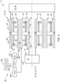
FIG. 3 is a partial schematic sectional illustration of an assembly for the aircraft propulsion system through the turbine electric transmission. -
FIG. 4 is a partial schematic sectional illustration of an alternative assembly for the aircraft propulsion system through the turbine electric transmission. -
FIG. 5 is a partial schematic sectional illustration of an assembly for the aircraft propulsion system through a propulsor electric transmission. -
FIG. 6 is a partial schematic sectional illustration of an alternative assembly for the aircraft propulsion system through the propulsor electric transmission. -
FIG. 1 illustrates apropulsion system 10 for an aircraft. The aircraft may be an airplane, a helicopter, a drone (e.g., an unmanned aerial vehicle (UAV)) or any other manned or unmanned aerial vehicle or system. Theaircraft propulsion system 10 ofFIG. 1 includes apropulsor rotor 12 and anaircraft powerplant 14 configured to drive rotation of thepropulsor rotor 12. - The
propulsor rotor 12 is an air mover operable to generate thrust and/or lift for the aircraft. Thispropulsor rotor 12 may be configured as an open, un-ducted propulsor rotor or a ducted propulsor rotor. Examples of the un-ducted propulsor rotor include a propeller rotor for a propeller propulsion system (e.g., a turboprop propulsion system), a rotorcraft rotor (e.g., a main helicopter rotor) for a rotorcraft propulsion system (e.g., a turboshaft propulsion system), a propfan rotor for a propfan propulsion system, and a pusher fan rotor for a pusher fan propulsion system. An example of the ducted propulsor rotor is a fan rotor for a turbofan propulsion system. The present disclosure, however, is not limited to the foregoing exemplary un-ducted and ducted propulsor rotors. Thepropulsor rotor 12 ofFIG. 1 includes a propulsor rotor base (e.g., a disk or a hub) and a plurality of propulsor rotor blades (e.g., airfoils). The propulsor rotor blades are arranged circumferentially around the propulsor rotor base in an array. Each of the propulsor rotor blades is connected to (e.g., formed integral with or mechanically fastened, welded, brazed and/or otherwise attached to) and projects radially out from the propulsor rotor base. - The
aircraft powerplant 14 may be configured as a turbo-compounded heat engine. Theaircraft powerplant 14 ofFIG. 1 , for example, includes a heat engine 16, apowerplant compressor section 18, a powerplant turbine section 20 and one or more transmissions 22 and 24; e.g., speed change devices. Theaircraft powerplant 14 also includes apowerplant flowpath 26 and afuel system 28. - The heat engine 16 may be configured as or otherwise include an intermittent internal combustion (IC) engine 30 ("intermittent combustion engine"). The intermittent combustion engine 30 is an internal combustion (IC) engine in which a mixture of fuel and air is intermittently (e.g., periodically) deflagration within one or
more combustion zones 32. Eachcombustion zone 32 may be configured as or otherwise include a combustion chamber, a piston bore and/or the like within the intermittent combustion engine 30 (the heat engine 16). The deflagration of the fuel-air mixture within thecombustion zones 32 drives rotation of an internalengine rotating assembly 34 of the intermittent combustion engine 30 (the heat engine 16). Thisengine rotating assembly 34 may include one or more pistons and/or rotors in and/or along thecombustion zones 32, and is rotatable about anengine axis 36. Examples of the intermittent combustion engine 30 include, but are not limited to, a reciprocating piston engine (e.g., an inline (I) engine, a V-engine, a W-engine, etc.) and a rotary engine (e.g., a Wankel engine). The present disclosure, however, is not limited to intermittent combustion engine applications. - The
compressor section 18 includes abladed compressor rotor 38. Thiscompressor rotor 38 may be configured as a radial flow compressor rotor; e.g., an axial inflow-radial outflow compressor rotor, a centrifugal compressor rotor, a compressor impeller, etc. Alternatively, thecompressor rotor 38 may be configured as an axial flow compressor rotor; e.g., an axial inflow-axial outflow compressor rotor. Thecompressor rotor 38 ofFIG. 1 includes a compressor rotor base (e.g., a disk or a hub) and a plurality of compressor rotor blades (e.g., airfoils, vanes, etc.). The compressor rotor blades are arranged circumferentially around the compressor rotor base in an array. Each of the compressor rotor blades is connected to (e.g., formed integral with or mechanically fastened, welded, brazed and/or otherwise attached to) and projects radially out from the compressor rotor base. Thecompressor rotor 38 is rotatable about acompressor axis 40. - The turbine section 20 includes a bladed
turbine rotor 42. Thisturbine rotor 42 may be configured as a radial flow turbine rotor; e.g., a radial inflow-axial outflow turbine rotor, a centrifugal turbine rotor, a turbine wheel, etc. Alternatively, theturbine rotor 42 may be configured as an axial flow turbine rotor; e.g., an axial inflow-axial outflow turbine rotor. Theturbine rotor 42 ofFIG. 1 includes a turbine rotor base (e.g., a disk or a hub) and a plurality of turbine rotor blades (e.g., airfoils, vanes, etc.). The turbine rotor blades are arranged circumferentially around the turbine rotor base in an array. Each of the turbine rotor blades is connected to (e.g., formed integral with or mechanically fastened, welded, brazed and/or otherwise attached to) and projects radially out from the turbine rotor base. Theturbine rotor 42 is rotatable about aturbine axis 44, whichturbine axis 44 may be parallel (e.g., coaxial) with thecompressor axis 40. - The
turbine rotor 42 may be coupled to thecompressor rotor 38 through a turbo-compressor shaft 46. At least (or only) thecompressor rotor 38, theturbine rotor 42 and the turbo-compressor shaft 46 may collectively form a turbo-compressor rotating assembly 48; e.g., a spool. - The turbo-
compressor rotating assembly 48 and itsturbine rotor 42 are operatively coupled to and rotatable with theengine rotating assembly 34 through the turbine transmission 22. With this arrangement, the turbo-compressor rotating assembly 48 and itsturbine rotor 42 may rotate at a different (e.g., faster) rotational velocity than theengine rotating assembly 34. Theengine rotating assembly 34 is operatively coupled to and rotatable with thepropulsor rotor 12 through the propulsor transmission 24. With this arrangement, theengine rotating assembly 34 may rotate at a different (e.g., faster) rotational velocity than thepropulsor rotor 12. The turbo-compressor rotating assembly 48 and itsturbine rotor 42 are thereby also operatively coupled to and rotatable with the propulsor rotor 12 (e.g., sequentially) through the turbine transmission 22, theengine rotating assembly 34 and the propulsor transmission 24. - The
powerplant flowpath 26 ofFIG. 1 longitudinally extends sequentially through the compressor section 18 (e.g., across the compressor rotor 38), the heat engine 16 (e.g., along / across the pistons and/or the rotors of the engine rotating assembly 34) and the turbine section 20 (e.g., across the turbine rotor 42) from anairflow inlet 50 into thepowerplant flowpath 26 to a combustion products exhaust 52 from thepowerplant flowpath 26. Theflowpath inlet 50 may also be an airflow inlet into theaircraft powerplant 14. Theflowpath exhaust 52 may also be a combustion products exhaust from theaircraft powerplant 14. - The
fuel system 28 is configured to deliver fuel to thecombustion zones 32 within the heat engine 16; e.g., the intermittent combustion engine 30. Thefuel system 28 ofFIG. 1 , for example, includes afuel circuit 54, afuel reservoir 56, afuel regulator 58 and one ormore fuel injectors 60. - The
fuel circuit 54 is fluidly coupled with an outlet of thefuel reservoir 56. Thisfuel circuit 54 extends longitudinally through thefuel regulator 58 to thefuel injectors 60. Thefuel circuit 54 thereby fluidly couples thefuel reservoir 56 and its reservoir outlet to thefuel injectors 60 through thefuel regulator 58. - The
fuel reservoir 56 is configured to store fuel before, during and/or after aircraft powerplant operation. Thefuel reservoir 56, for example, may be configured as or otherwise include a tank, a cylinder, a pressure vessel, a bladder or any other type of fuel storage container. - The
fuel regulator 58 is configured to selectively direct and/or meter a flow of the fuel from thefuel reservoir 56 to one or more of thefuel injectors 60. Thefuel regulator 58, for example, may be configured as or otherwise include a fuel pump and/or a valve (or valve system). - The
fuel injectors 60 are arranged with (e.g., on, along, in, etc.) thecombustion zones 32. Thesefuel injectors 60 are configured to direct (e.g., inject) the fuel into thecombustion zones 32 to mix with compressed air for subsequent combustion. - During operation, the
fuel system 28 delivers (e.g., injects) fuel into thecombustion zones 32. The fuel is mixed with compressed air within thecombustion zones 32. This fuel-air mixture is ignited, and combustion products generated therefrom drive rotation of theengine rotating assembly 34. The rotation of theengine rotating assembly 34 drives rotation of thepropulsor rotor 12 through the propulsor transmission 24, and therotating propulsor rotor 12 generates aircraft thrust and/or lift. The combustion products further flow out of the heat engine 16 (e.g., the intermittent combustion engine 30) into the turbine section 20 and drive rotation of theturbine rotor 42. The rotation of theturbine rotor 42 drives rotation of thecompressor rotor 38, and therotating compressor rotor 38 compresses air entering theaircraft powerplant 14 and itspowerplant flowpath 26 through theflowpath inlet 50 to provide the compressed air to the heat engine 16. The rotation of theturbine rotor 42 also drives rotation of (e.g., boosts mechanical power to) theengine rotating assembly 34 through the turbine transmission 22. The rotation of theturbine rotor 42 may thereby also drive rotation of (e.g., boost mechanical power to) thepropulsor rotor 12 through thepowerplant members 22, 34 and 24. - As described above, the turbine transmission 22 facilitates operation of the turbo-
compressor rotating assembly 48 at a different rotational velocity than theengine rotating assembly 34. The propulsor transmission 24 facilitates operation of theengine rotating assembly 34 at a different rotational velocity than thepropulsor rotor 12. Thesepropulsion system members - Under certain conditions, there may be a rotational velocity mismatch across the turbine transmission 22 between the turbo-
compressor rotating assembly 48 and theengine rotating assembly 34. This mismatch may be accommodated using a mechanical transmission, where the mechanical transmission includes a transmission geartrain (e.g., a reduction gearbox, an epicyclic geartrain, etc.) paired with a variable speed drive (VSD) (e.g., a hydraulic continuously variable transmission (CVT)). Such a mechanical transmission, however, may be relatively complex as well as increase lubrication and cooling demands on powerplant lubrication and cooling systems. Therefore, to reduce system complexity as well as to reduce lubrication and cooling demands, the turbine transmission 22 may be configured as a turbine electric transmission 62; e.g., an electric geartrain. - Referring to
FIGS. 2 and3 , the turbine electric transmission 62 may be configured as or otherwise include a dual rotor electric machine. The turbine electric transmission 62 ofFIGS. 2 and3 , for example, includes an inner electric machine rotor 64 ("inner rotor"), an outer electric machine rotor 66 ("outer rotor"), an inner electric machine stator 67 ("inner stator") and an outer electric machine stator 68 ("outer stator"). Theinner rotor 64 and theouter rotor 66 are each rotatable about a common (the same)transmission axis 70, whichtransmission axis 70 may be an axial centerline of one or more of theelectric machine members transmission axis 70 ofFIG. 3 may also be coaxial with one or more of theaxes FIG. 1 . - The
inner rotor 64 ofFIG. 3 extends axially along thetransmission axis 70. Theinner rotor 64 extends radially to anouter side 72 of theinner rotor 64. Theinner rotor 64 extends circumferentially about (e.g., completely around) thetransmission axis 70. Theinner rotor 64 includes an inner hub 74 (e.g., tubular or cylindrical hub) and one or more innerpermanent magnets 76 distributed circumferentially about theinner hub 74 and thetransmission axis 70 in an array. Each of these innerpermanent magnets 76 is disposed at the inner rotorouter side 72. Each of the innerpermanent magnets 76 is fixed to theinner hub 74. An inner magnet retention device (not shown for ease of illustration) such as a sleeve or a carbon fiber wrap may be arranged circumferentially over outer surfaces of innerpermanent magnets 76. This inner magnet retention device may thereby form theouter side 72 of theinner rotor 64. - The
outer rotor 66 extends axially along thetransmission axis 70. Theouter rotor 66 ofFIG. 3 also extends axially along (e.g., at least partially or completely overlapping) theinner rotor 64. Theouter rotor 66 extends radially between and to aninner side 78 of theouter rotor 66 and anouter side 80 of theouter rotor 66. The outer rotorinner side 78 is disposed radially opposite (e.g., faces) and spaced radially from the inner rotorouter side 72. Theouter rotor 66 extends circumferentially about (e.g., completely around) thetransmission axis 70. Theouter rotor 66 also extends circumferentially about (e.g., circumscribes) theinner rotor 64. Theouter rotor 66 includes an outer hub 82 (e.g., tubular hub) and one or more outerpermanent magnets 84 distributed circumferentially about thetransmission axis 70 in an annular array. Each of these outerpermanent magnets 84 is disposed at the outer rotorinner side 78, where theouter hub 82 is radially outward of and circumscribes the array of the outerpermanent magnets 84. Each of the outerpermanent magnets 84 is fixed to theouter hub 82. - The
inner stator 67 ofFIG. 3 is arranged radially between and is axially aligned with theinner rotor 64 and theouter rotor 66. Thisinner stator 67 extends axially along thetransmission axis 70. Theinner stator 67 ofFIG. 3 also extend axially along (e.g., at least partially or completely overlapping) theinner rotor 64 and theouter rotor 66. Theinner stator 67 extends radially between and to aninner side 85 of theinner stator 67 and anouter side 86 of theinner stator 67. The inner statorinner side 85 is disposed radially opposite (e.g., faces) and is (e.g., slightly) spaced from the inner rotorouter side 72. Theinner stator 68 includes one or more innerelectrical coils 90 distributed circumferentially about thetransmission axis 70. - The
outer stator 68 ofFIG. 3 is arranged radially between and is axially aligned with theinner rotor 64 and theouter rotor 66. More particularly, theouter stator 68 ofFIG. 3 is arranged radially between and is axially aligned with theinner stator 67 and theouter rotor 66. Thisouter stator 68 extends axially along thetransmission axis 70. Theouter stator 68 ofFIG. 3 also extend axially along (e.g., at least partially or completely overlapping) theinner rotor 64, theouter rotor 66 and theinner stator 67. Theouter stator 68 extends radially between and to aninner side 87 of theouter stator 68 and anouter side 88 of theouter stator 68. The outer statorinner side 87 is disposed radially opposite (e.g., faces) and is (e.g., slightly) spaced from the inner rotorouter side 72. The outer statorinner side 87 is disposed radially opposite (e.g., faces) and is spaced from the inner statorouter side 86. The outer statorouter side 88 is disposed radially opposite (e.g., faces) and is (e.g., slightly) spaced from the outer rotorinner side 78. Theouter stator 68 includes one or more outerelectrical coils 92 distributed circumferentially about thetransmission axis 70. - The
inner rotor 64 ofFIG. 3 is mechanically coupled to theengine rotating assembly 34. Theengine rotating assembly 34 is thereby operatively coupled to the turbine transmission 22 through itsinner rotor 64. Theouter rotor 66 ofFIG. 3 is mechanically coupled to the turbo-compressor rotating assembly 48 and itsturbine rotor 42. The turbo-compressor rotating assembly 48 is thereby operatively coupled to the turbine transmission 22 through itsouter rotor 66. Each of thestators aircraft powerplant 14. - The turbine electric transmission 62 may be operated in various modes of operation. Examples of these modes include, but are not limited to, a transmission mode, a power boost mode, a power generator mode and a starter mode.
- During the transmission mode, (a) at least (or only) the
outer rotor 66 and theouter stator 68 are collectively operated as anelectric generator 94 and (b) at least (or only) theinner rotor 64 and theinner stator 67 are collectively operated as anelectric motor 96. Theelectric generator 94 is operated to convert mechanical power received from the turbo-compressor rotating assembly 48 and itsturbine rotor 42 into electricity. The turbo-compressor rotating assembly 48 and itsturbine rotor 42, for example, may drive rotation of theouter rotor 66. The rotation of theouter rotor 66 may generate a rotatingmagnetic field 98 with theouter stator 68, and theouter stator 68 may convert energy from the rotatingmagnetic field 98 into an electric potential and current - the electricity. Theelectric generator 94 may then provide at least some this electricity through anelectric power system 99 to theelectric motor 96 for further use. Thepower system 99 ofFIG. 3 includes arectifier 99A and aninverter 99B. Therectifier 99A is configured to convert alternating current (AC) electricity received from theelectric generator 94 into direct current (DC) electricity. Theinverter 99B is configured to convert the DC electricity back into AC current for powering theelectric motor 96. Thepower system 99 may also include (or otherwise be electrically coupled to) anenergy storage 99C (e.g., a battery, a battery bank, one or more capacitors, etc.), whichenergy storage 99C may be utilized to smooth out the electrical current through thepower system 99. Upon receiving the AC electricity, theelectric motor 96 is operated to convert the electricity into mechanical power. Theinner stator 67, for example, may generate a rotatingmagnetic field 100 with theinner rotor 64 using the electricity. This rotatingmagnetic field 100 may drive rotation of theinner rotor 64. Theinner rotor 64 may thereby drive rotation of theengine rotating assembly 34. This mechanical power may be provided to theengine rotating assembly 34 to boost mechanical power generated by combustion within the heat engine 16 (seeFIG. 1 ). - With the foregoing arrangement, the turbine electric transmission 62 may provide a speed change device (e.g., a differential) between the turbo-
compressor rotating assembly 48 and theengine rotating assembly 34. Thepower system 99 may be operated to regulate the electrical current provided to theelectric motor 96. Referring toFIG. 3 , the turbine electric transmission 62 may also accommodate a rotational velocity mismatch across the turbine electric transmission 62 between the turbo-compressor rotating assembly 48 and theengine rotating assembly 34 since there is no direct mechanical coupling between the turbo-compressor rotating assembly 48 and theengine rotating assembly 34. - In addition to the foregoing, the turbine electric transmission 62 may provide an integrated clutch functionality. For example, to decouple the turbo-
compressor rotating assembly 48 from theengine rotating assembly 34, the electricity generated by theelectric generator 94 may be directed to theenergy storage 99C and/or one or more other devices rather than theelectric motor 96. - The
power system members electric generator 94 and/or the electric motor 96 (or more generally the turbine electric transmission 62) through electrical circuitry; e.g., a power bus. This electrical circuitry may include one or more electrical leads 106 (e.g., high voltage lines) and one or more additional electrical devices (not shown for ease of illustration) for conditioning, metering, regulating and/or otherwise controlling electrical power transfer between the electric machine and theenergy storage 99C. Examples of the electrical devices include, but are not limited to, switches, current regulators, converters and buffers. - During the power boost mode, the turbine electric transmission 62 may generally operate as described above with respect to the transmission mode. In the power boost mode, however, the
electric motor 96 may receive additional electricity from theenergy storage 99C in addition to the electricity generated by theelectric generator 94. This additional electricity is provided to theelectric motor 96 to boost a mechanical power output of theelectric motor 96 and itsinner rotor 64 to theengine rotating assembly 34. - During the power generator mode, the turbine electric transmission 62 may generally operate as described above with respect to the transmission mode. In the power generator mode, however, some of the electricity generated by the
electric generator 94 may be directed to theelectric motor 96 for powering theelectric motor 96, and some of the electricity generated by theelectric generator 94 may be directed to theenergy storage 99C for storage and/or to one or more other aircraft systems. - During the starter mode, at least (or only) the
inner rotor 64 and theinner stator 67 are collectively operated as theelectric motor 96 as described above with respect to the transmission mode. In the starter mode, however, the electricity delivered to theelectric motor 96 for operation may be provided (e.g., solely) by theenergy storage 99C. For example, during a cold start of theaircraft powerplant 14, both theengine rotating assembly 34 and the turbo-compressor rotating assembly 48 may be stationary. Theelectric motor 96 may be used to drive rotation of theengine rotating assembly 34 to facilitate startup of the heat engine 16; e.g., the intermittent combustion engine 30 ofFIG. 1 . It is contemplated therefore the turbine electric transmission 62 may replace a traditional dedicated starter motor for the heat engine 16. - In some embodiments, referring to
FIG. 3 , theinner rotor 64 may be mechanically coupled to theengine rotating assembly 34 and theouter rotor 66 may be mechanically coupled to the turbo-compressor rotating assembly 48 as described above. In other embodiments however, referring toFIG. 4 , theinner rotor 64 may alternatively be mechanically coupled to the turbo-compressor rotating assembly 48 and theouter rotor 66 may alternatively be mechanically coupled to theengine rotating assembly 34. With such an arrangement, (a) at least (or only) theinner rotor 64 and theinner stator 67 are collectively operated as theelectric generator 94 and (b) at least (or only) theouter rotor 66 and theouter stator 68 are collectively operated as theelectric motor 96. - In some embodiments, the propulsor transmission 24 of
FIG. 1 may be configured as a mechanical transmission. The propulsor transmission 24, for example, may be configured as or otherwise include a reduction gearbox, an epicyclic geartrain, etc. With such an arrangement, an additionalelectric motor 108 may be provided to further (e.g., selectively) drive rotation of thepropulsor rotor 12. The propulsor transmission 24, for example, may couple both the heat engine 16 and the additionalelectric motor 108 to the propulsor rotor 12 (e.g., in parallel). - In some embodiments, the propulsor transmission 24 may alternatively be configured as a propulsor electric transmission 110. Referring to
FIG. 5 , the propulsor electric transmission 110 may be configured as or otherwise include a dual rotor electric machine. This propulsor electric transmission 110 may have a similar (or the same) configuration as the turbine electric transmission 62 ofFIGS. 2 and3 described above. However, an inner electric machine rotor 112 ("inner rotor") of the propulsor electric transmission 110 is mechanically or otherwise coupled to thepropulsor rotor 12, and an outer electric machine rotor 114 ("outer rotor") of the propulsor electric transmission 110 is mechanically or otherwise coupled to theengine rotating assembly 34. Here, (a) at least (or only) theouter rotor 114 and an outer electric machine stator 116 ("outer stator") are collectively operated as anelectric generator 118 and (b) at least (or only) theinner rotor 112 and an inner electric machine stator 115 ("inner stator") are collectively operated as anelectric motor 120. Of course, it is contemplated couplings to therotors FIG. 6 . Referring again toFIG. 5 , the propulsor electric transmission 110 may also have a similar (or the same) operability as the turbine electric transmission 62 ofFIGS. 2 and3 described above. For example, in a transmission mode, theengine rotating assembly 34 may mechanically power theelectric generator 118, and theelectric motor 120 may be powered by electricity generated by theelectric generator 118 to drive rotation of thepropulsor rotor 12. In a power boost mode, theelectric motor 120 may receive additional electricity from theenergy storage 99C. In a power generator mode, at least some of the electricity generated by theelectric generator 118 may be directed to theenergy storage 99C and/or elsewhere. In a starter mode, a mode of theelectric generator 118 may be reversed (e.g., operated as an electric motor) in order to drive rotation of theengine rotating assembly 34 to facilitate startup of the heat engine 16. - Each electric transmission 62, 110 is described above as a dual rotor electric machine. More particularly, each dual rotor electric machine is described above as a radial dual rotor electric machine where the
respective stators inner rotor outer rotor respective stators respective rotors aircraft powerplant 14 includes the propulsor electric transmission 110, it is contemplated the turbine transmission 22 may alternatively be configured as or otherwise include a mechanical transmission. - While various embodiments of the present disclosure have been described, it will be apparent to those of ordinary skill in the art that many more embodiments and implementations are possible within the scope of the disclosure. For example, the present disclosure as described herein includes several aspects and embodiments that include particular features. Although these features may be described individually, it is within the scope of the present disclosure that some or all of these features may be combined with any one of the aspects and remain within the scope of the disclosure. Accordingly, the present disclosure is not to be restricted except in light of the attached claims and their equivalents.
Claims (14)
- A system (10) for an aircraft, comprising:a propulsor rotor (12); anda powerplant (14) configured to drive rotation of the propulsor rotor (12), the powerplant (14) including a turbo-compounded intermittent internal combustion engine (16) and a dual rotor electric machine (22, 62);the turbo-compounded intermittent internal combustion engine (16) comprising a turbine rotor (42) operatively coupled to the propulsor rotor (12) through the dual rotor electric machine (22, 62); andthe dual rotor electric machine (22, 62) including a first rotor (64, 66), a second rotor (64, 66), a first stator (67, 68) and a second stator (67, 68), and the first stator (67, 68) and the second stator (67, 68) arranged radially between and axially aligned with the first rotor (64, 66) and the second rotor (64, 66).
- The system of claim 1, whereinthe first rotor (64, 66) and the first stator (67, 68) form an electric motor (96); andthe second rotor (64, 66) and the second stator (67, 68) form an electric generator (94) configured to generate electricity for powering the electric motor (96).
- The system of claim 2, further comprising a power source (99C) configured to selectively provide additional electricity to the electric motor (96) to boost a mechanical power output of the electric motor (96).
- The system of claim 2 or 3, whereinthe first rotor (66) circumscribes the first stator (68);the first stator (68) circumscribes the second stator (67); andthe second stator (67) circumscribes the second rotor (64).
- The system of claim 2 or 3, whereinthe second rotor (66) circumscribes the second stator (68);the second stator (68) circumscribes the first stator (67); andthe first stator (67) circumscribes the first rotor (64).
- The system of any preceding claim, whereinthe turbo-compounded intermittent internal combustion engine (16) further comprises an internal combustion engine (30);the internal combustion engine (30) comprises an engine rotating assembly (34); andthe turbine rotor (42) is operatively coupled to the engine rotating assembly (34) through the dual rotor electric machine (22, 62).
- The system of claim 6, whereinthe dual rotor electric machine (22, 62) is configured as a transmission between the turbine rotor (42) and the engine rotating assembly (34) during a first mode of operation; andthe dual rotor electric machine (22, 62) is configured as a starter motor for the internal combustion engine (30) during a second mode of operation.
- The system of claim 6 or 7, wherein the internal combustion engine (30) comprises a rotary engine.
- The system of claim 6, 7 or 8, whereinthe powerplant (14) further includes an electric gearbox (24, 110); andthe engine rotating assembly (34) is operatively coupled to the propulsor rotor (12) through the electric gearbox (24, 110).
- The system of claim 9, wherein the electric gearbox (24, 110) comprises a second dual rotor electric machine.
- The system of any of claims 6 to 10, whereinthe turbo-compounded intermittent internal combustion engine (16) further comprises an/the internal combustion engine (30);the internal combustion engine (30) comprises an/the engine rotating assembly (34); andthe engine rotating assembly (34) is operatively coupled to the propulsor rotor (12) through the dual rotor electric machine (22, 62).
- The system of any of claims 6 to 11, whereinthe dual rotor electric machine (22, 62) is configured as a transmission between the engine rotating assembly (34) and the propulsor rotor (12) during a first mode of operation; andthe dual rotor electric machine (22, 62) is configured as a starter motor for the internal combustion engine (30) during a second mode of operation.
- The system of any preceding claim, wherein the propulsor rotor (12) is an un-ducted propulsor rotor.
- The system of any of claims 1 to 12, wherein the propulsor rotor (12) is a ducted propulsor rotor.
Applications Claiming Priority (1)
| Application Number | Priority Date | Filing Date | Title |
|---|---|---|---|
| US18/224,942 US12163468B1 (en) | 2023-07-21 | 2023-07-21 | Aircraft powerplant with electric transmission(s) |
Publications (1)
| Publication Number | Publication Date |
|---|---|
| EP4495006A1 true EP4495006A1 (en) | 2025-01-22 |
Family
ID=91961770
Family Applications (1)
| Application Number | Title | Priority Date | Filing Date |
|---|---|---|---|
| EP24189895.6A Pending EP4495006A1 (en) | 2023-07-21 | 2024-07-19 | Aircraft powerplant with electric transmission(s) |
Country Status (3)
| Country | Link |
|---|---|
| US (1) | US12163468B1 (en) |
| EP (1) | EP4495006A1 (en) |
| CA (1) | CA3248885A1 (en) |
Citations (6)
| Publication number | Priority date | Publication date | Assignee | Title |
|---|---|---|---|---|
| US20080174194A1 (en) * | 2006-12-07 | 2008-07-24 | General Electric Company | Double-Sided Starter/Generator for Aircrafts |
| US20130174533A1 (en) * | 2012-01-06 | 2013-07-11 | Hamilton Sundstrand Corporation | Magnetically coupled contra-rotating propulsion stages |
| EP3348821B1 (en) * | 2017-01-16 | 2020-03-04 | Pratt & Whitney Canada Corp. | Turbofan engine assembly with intercooler |
| US20200277066A1 (en) * | 2019-03-01 | 2020-09-03 | Pratt & Whitney Canada Corp. | Engine layouts and associated compartmentalization for aircraft having hybrid-electric propulsion system |
| US20210355881A1 (en) * | 2020-05-15 | 2021-11-18 | Pratt & Whitney Canada Corp. | Through-flow gas turbine engine with electric motor and electric generator |
| US20220003128A1 (en) * | 2020-07-06 | 2022-01-06 | General Electric Company | Dual rotor electric machine |
Family Cites Families (8)
| Publication number | Priority date | Publication date | Assignee | Title |
|---|---|---|---|---|
| US7791235B2 (en) | 2006-12-22 | 2010-09-07 | General Electric Company | Variable magnetic coupling of rotating machinery |
| US7690188B2 (en) * | 2007-03-02 | 2010-04-06 | United Technologies Corporation | Combination engines for aircraft |
| DE102009022168A1 (en) | 2009-05-20 | 2010-12-02 | Daimler Ag | Hybrid drive for vehicle, has combustion engine and electrical machine that is operated as electric motor or generator, where electrical machine has inner rotor and outer rotor |
| DE202014002486U1 (en) | 2014-03-21 | 2015-06-26 | Claus-Georg Müller | Rotary piston engine and hybrid drive with such a rotary piston engine |
| US10253726B2 (en) * | 2015-08-07 | 2019-04-09 | Pratt & Whitney Canada Corp. | Engine assembly with combined engine and cooling exhaust |
| US11735988B2 (en) | 2019-01-31 | 2023-08-22 | General Electric Company | Dual rotor electric machine |
| DE102021101408A1 (en) * | 2021-01-22 | 2022-07-28 | Feaam Gmbh | ELECTRICAL MACHINE, POWER SYSTEM AND ITS USE |
| CN115158647B (en) | 2022-07-15 | 2026-01-20 | 中国航发北京航空材料研究院 | A coaxial dual-rotor thrust system based on magnetic gears |
-
2023
- 2023-07-21 US US18/224,942 patent/US12163468B1/en active Active
-
2024
- 2024-07-16 CA CA3248885A patent/CA3248885A1/en active Pending
- 2024-07-19 EP EP24189895.6A patent/EP4495006A1/en active Pending
Patent Citations (6)
| Publication number | Priority date | Publication date | Assignee | Title |
|---|---|---|---|---|
| US20080174194A1 (en) * | 2006-12-07 | 2008-07-24 | General Electric Company | Double-Sided Starter/Generator for Aircrafts |
| US20130174533A1 (en) * | 2012-01-06 | 2013-07-11 | Hamilton Sundstrand Corporation | Magnetically coupled contra-rotating propulsion stages |
| EP3348821B1 (en) * | 2017-01-16 | 2020-03-04 | Pratt & Whitney Canada Corp. | Turbofan engine assembly with intercooler |
| US20200277066A1 (en) * | 2019-03-01 | 2020-09-03 | Pratt & Whitney Canada Corp. | Engine layouts and associated compartmentalization for aircraft having hybrid-electric propulsion system |
| US20210355881A1 (en) * | 2020-05-15 | 2021-11-18 | Pratt & Whitney Canada Corp. | Through-flow gas turbine engine with electric motor and electric generator |
| US20220003128A1 (en) * | 2020-07-06 | 2022-01-06 | General Electric Company | Dual rotor electric machine |
Also Published As
| Publication number | Publication date |
|---|---|
| US12163468B1 (en) | 2024-12-10 |
| CA3248885A1 (en) | 2025-06-05 |
Similar Documents
| Publication | Publication Date | Title |
|---|---|---|
| EP3957843B1 (en) | Hybrid through-flow gas turbine engine with electric motor and electric generator | |
| EP4464602A2 (en) | Mechanical disconnects for parallel power lanes in hybrid electric propulsion systems | |
| US12291347B2 (en) | Containment zone for an electric machine in a hybrid powerplant for an aircraft | |
| EP4390063A1 (en) | Exhaust duct for hybrid aircraft powerplant | |
| CN119957366A (en) | Aircraft engine fuel supply circuit | |
| EP4286657A1 (en) | Gas turbine engine with electric machine in engine core | |
| US20240243632A1 (en) | Electrical energy system having different axial lengths for efficient power generation | |
| US12017790B2 (en) | Aircraft auxiliary power unit | |
| US12163468B1 (en) | Aircraft powerplant with electric transmission(s) | |
| EP4442982A1 (en) | Boosting gas turbine engine power with fluid motor | |
| EP4509703A1 (en) | Aircraft powerplant with electric powertrain | |
| EP4389605A2 (en) | Electric aircraft propulsion unit(s) with multiple propulsor rotors | |
| US12523161B1 (en) | Aircraft powerplant gearbox with selectable power coupler | |
| US12404811B1 (en) | Aircraft powerplant gearbox with selectable power coupler | |
| US11933218B2 (en) | System with multiple forced induction engines | |
| US20260139629A1 (en) | Accessory gearbox with multiple power transfer systems | |
| US12116899B2 (en) | Variable speed pumping system with electric pump motor generator | |
| EP4506257A1 (en) | Power management between a heat engine and an electric machine for an aircraft powerplant | |
| US20250038619A1 (en) | Air-cooled electric machine | |
| EP4653681A2 (en) | Differential geartrain for aircraft propulsion system | |
| US20250043733A1 (en) | Hybrid turbofan engine with a planetary gearset for blending power between an electric output and variable-thrust bypass fan |
Legal Events
| Date | Code | Title | Description |
|---|---|---|---|
| PUAI | Public reference made under article 153(3) epc to a published international application that has entered the european phase |
Free format text: ORIGINAL CODE: 0009012 |
|
| STAA | Information on the status of an ep patent application or granted ep patent |
Free format text: STATUS: THE APPLICATION HAS BEEN PUBLISHED |
|
| AK | Designated contracting states |
Kind code of ref document: A1 Designated state(s): AL AT BE BG CH CY CZ DE DK EE ES FI FR GB GR HR HU IE IS IT LI LT LU LV MC ME MK MT NL NO PL PT RO RS SE SI SK SM TR |
|
| STAA | Information on the status of an ep patent application or granted ep patent |
Free format text: STATUS: REQUEST FOR EXAMINATION WAS MADE |
|
| 17P | Request for examination filed |
Effective date: 20250722 |
|
| STAA | Information on the status of an ep patent application or granted ep patent |
Free format text: STATUS: EXAMINATION IS IN PROGRESS |
|
| 17Q | First examination report despatched |
Effective date: 20260225 |