EP4494941A1 - Lamp electronic control unit - Google Patents
Lamp electronic control unit Download PDFInfo
- Publication number
- EP4494941A1 EP4494941A1 EP23770730.2A EP23770730A EP4494941A1 EP 4494941 A1 EP4494941 A1 EP 4494941A1 EP 23770730 A EP23770730 A EP 23770730A EP 4494941 A1 EP4494941 A1 EP 4494941A1
- Authority
- EP
- European Patent Office
- Prior art keywords
- lamp
- power supply
- pin
- output
- additional
- Prior art date
- Legal status (The legal status is an assumption and is not a legal conclusion. Google has not performed a legal analysis and makes no representation as to the accuracy of the status listed.)
- Pending
Links
Images


Classifications
-
- H—ELECTRICITY
- H05—ELECTRIC TECHNIQUES NOT OTHERWISE PROVIDED FOR
- H05B—ELECTRIC HEATING; ELECTRIC LIGHT SOURCES NOT OTHERWISE PROVIDED FOR; CIRCUIT ARRANGEMENTS FOR ELECTRIC LIGHT SOURCES, IN GENERAL
- H05B47/00—Circuit arrangements for operating light sources in general, i.e. where the type of light source is not relevant
- H05B47/10—Controlling the light source
- H05B47/17—Operational modes, e.g. switching from manual to automatic mode or prohibiting specific operations
-
- B—PERFORMING OPERATIONS; TRANSPORTING
- B60—VEHICLES IN GENERAL
- B60Q—ARRANGEMENT OF SIGNALLING OR LIGHTING DEVICES, THE MOUNTING OR SUPPORTING THEREOF OR CIRCUITS THEREFOR, FOR VEHICLES IN GENERAL
- B60Q1/00—Arrangement of optical signalling or lighting devices, the mounting or supporting thereof or circuits therefor
- B60Q1/02—Arrangement of optical signalling or lighting devices, the mounting or supporting thereof or circuits therefor the devices being primarily intended to illuminate the way ahead or to illuminate other areas of way or environments
-
- H—ELECTRICITY
- H05—ELECTRIC TECHNIQUES NOT OTHERWISE PROVIDED FOR
- H05B—ELECTRIC HEATING; ELECTRIC LIGHT SOURCES NOT OTHERWISE PROVIDED FOR; CIRCUIT ARRANGEMENTS FOR ELECTRIC LIGHT SOURCES, IN GENERAL
- H05B41/00—Circuit arrangements or apparatus for igniting or operating discharge lamps
- H05B41/14—Circuit arrangements
- H05B41/26—Circuit arrangements in which the lamp is fed by power derived from DC by means of a converter, e.g. by high-voltage DC
- H05B41/28—Circuit arrangements in which the lamp is fed by power derived from DC by means of a converter, e.g. by high-voltage DC using static converters
- H05B41/282—Circuit arrangements in which the lamp is fed by power derived from DC by means of a converter, e.g. by high-voltage DC using static converters with semiconductor devices
- H05B41/285—Arrangements for protecting lamps or circuits against abnormal operating conditions
- H05B41/2851—Arrangements for protecting lamps or circuits against abnormal operating conditions for protecting the circuit against abnormal operating conditions
- H05B41/2855—Arrangements for protecting lamps or circuits against abnormal operating conditions for protecting the circuit against abnormal operating conditions against abnormal lamp operating conditions
-
- H—ELECTRICITY
- H05—ELECTRIC TECHNIQUES NOT OTHERWISE PROVIDED FOR
- H05B—ELECTRIC HEATING; ELECTRIC LIGHT SOURCES NOT OTHERWISE PROVIDED FOR; CIRCUIT ARRANGEMENTS FOR ELECTRIC LIGHT SOURCES, IN GENERAL
- H05B47/00—Circuit arrangements for operating light sources in general, i.e. where the type of light source is not relevant
- H05B47/10—Controlling the light source
- H05B47/175—Controlling the light source by remote control
- H05B47/18—Controlling the light source by remote control via data-bus transmission
-
- B—PERFORMING OPERATIONS; TRANSPORTING
- B60—VEHICLES IN GENERAL
- B60Q—ARRANGEMENT OF SIGNALLING OR LIGHTING DEVICES, THE MOUNTING OR SUPPORTING THEREOF OR CIRCUITS THEREFOR, FOR VEHICLES IN GENERAL
- B60Q1/00—Arrangement of optical signalling or lighting devices, the mounting or supporting thereof or circuits therefor
- B60Q1/02—Arrangement of optical signalling or lighting devices, the mounting or supporting thereof or circuits therefor the devices being primarily intended to illuminate the way ahead or to illuminate other areas of way or environments
- B60Q1/04—Arrangement of optical signalling or lighting devices, the mounting or supporting thereof or circuits therefor the devices being primarily intended to illuminate the way ahead or to illuminate other areas of way or environments the devices being headlights
- B60Q1/06—Arrangement of optical signalling or lighting devices, the mounting or supporting thereof or circuits therefor the devices being primarily intended to illuminate the way ahead or to illuminate other areas of way or environments the devices being headlights adjustable, e.g. remotely-controlled from inside vehicle
- B60Q1/08—Arrangement of optical signalling or lighting devices, the mounting or supporting thereof or circuits therefor the devices being primarily intended to illuminate the way ahead or to illuminate other areas of way or environments the devices being headlights adjustable, e.g. remotely-controlled from inside vehicle automatically
- B60Q1/12—Arrangement of optical signalling or lighting devices, the mounting or supporting thereof or circuits therefor the devices being primarily intended to illuminate the way ahead or to illuminate other areas of way or environments the devices being headlights adjustable, e.g. remotely-controlled from inside vehicle automatically due to steering position
-
- B—PERFORMING OPERATIONS; TRANSPORTING
- B60—VEHICLES IN GENERAL
- B60Q—ARRANGEMENT OF SIGNALLING OR LIGHTING DEVICES, THE MOUNTING OR SUPPORTING THEREOF OR CIRCUITS THEREFOR, FOR VEHICLES IN GENERAL
- B60Q1/00—Arrangement of optical signalling or lighting devices, the mounting or supporting thereof or circuits therefor
- B60Q1/02—Arrangement of optical signalling or lighting devices, the mounting or supporting thereof or circuits therefor the devices being primarily intended to illuminate the way ahead or to illuminate other areas of way or environments
- B60Q1/04—Arrangement of optical signalling or lighting devices, the mounting or supporting thereof or circuits therefor the devices being primarily intended to illuminate the way ahead or to illuminate other areas of way or environments the devices being headlights
- B60Q1/14—Arrangement of optical signalling or lighting devices, the mounting or supporting thereof or circuits therefor the devices being primarily intended to illuminate the way ahead or to illuminate other areas of way or environments the devices being headlights having dimming means
- B60Q1/1407—General lighting circuits comprising dimming circuits
-
- B—PERFORMING OPERATIONS; TRANSPORTING
- B60—VEHICLES IN GENERAL
- B60Q—ARRANGEMENT OF SIGNALLING OR LIGHTING DEVICES, THE MOUNTING OR SUPPORTING THEREOF OR CIRCUITS THEREFOR, FOR VEHICLES IN GENERAL
- B60Q1/00—Arrangement of optical signalling or lighting devices, the mounting or supporting thereof or circuits therefor
- B60Q1/26—Arrangement of optical signalling or lighting devices, the mounting or supporting thereof or circuits therefor the devices being primarily intended to indicate the vehicle, or parts thereof, or to give signals, to other traffic
- B60Q1/34—Arrangement of optical signalling or lighting devices, the mounting or supporting thereof or circuits therefor the devices being primarily intended to indicate the vehicle, or parts thereof, or to give signals, to other traffic for indicating change of drive direction
- B60Q1/38—Arrangement of optical signalling or lighting devices, the mounting or supporting thereof or circuits therefor the devices being primarily intended to indicate the vehicle, or parts thereof, or to give signals, to other traffic for indicating change of drive direction using immovably-mounted light sources, e.g. fixed flashing lamps
-
- B—PERFORMING OPERATIONS; TRANSPORTING
- B60—VEHICLES IN GENERAL
- B60Q—ARRANGEMENT OF SIGNALLING OR LIGHTING DEVICES, THE MOUNTING OR SUPPORTING THEREOF OR CIRCUITS THEREFOR, FOR VEHICLES IN GENERAL
- B60Q2400/00—Special features or arrangements of exterior signal lamps for vehicles
- B60Q2400/30—Daytime running lights [DRL], e.g. circuits or arrangements therefor
Definitions
- the present disclosure relates to a lamp used for a vehicle such as an automobile.
- a head lamp is provided with a plurality of lamps having different roles, such as a low beam, a high beam, a turn signal lamp, a position lamp, and a daytime running lamp.
- cornering lamp side illumination lamp
- the cornering lamp is provided in association with the head lamp and irradiates the turning direction.
- Patent Literature 1 JP 2014-82147
- the interface of the cornering lamp has several different specifications.
- a lamp electronic control unit (ECU) incorporated in the head lamp has been designed for each specification of the cornering lamp. That is, an automobile manufacturer needs to select and design a different lamp ECU for each specification of the cornering lamp.
- the present disclosure has been made in view of such a problem, and an exemplary object of an aspect of the present disclosure is to provide a lamp ECU that can support an additional lamp having a different interface.
- a lamp electronic control unit capable of controlling an additional lamp.
- a lamp electronic control unit includes a connector including a power supply pin that receives battery voltage from a vehicle, a communication pin connected to a vehicle bus, and an output pin to be connected to the additional lamp, a power supply circuit including an output node connected to the output pin and structured to output power supply voltage from the output node in an enabled state, a first controller structured to control, in a first mode, the enabled state and a disabled state of the power supply circuit according to a turn-on/off instruction for the additional lamp received via the vehicle bus, an output interface circuit including an output node connected to the output pin, and a second controller structured to control, in a second mode, the output interface circuit according to the turn-on/off instruction.
- an additional lamp having a different interface can be controlled.
- a lamp electronic control unit can control an additional lamp.
- the lamp electronic control unit includes a connector including a power supply pin that receives battery voltage from a vehicle, a communication pin connected to a vehicle bus, and an output pin to be connected to the additional lamp, a power supply circuit including an output node connected to the output pin and structured to output power supply voltage from the output node in an enabled state, a first controller structured to control, in a first mode, the enabled state and a disabled state of the power supply circuit according to a turn-on/off instruction for the additional lamp received via the vehicle bus, an output interface circuit including an output node connected to the output pin, and a second controller structured to control, in a second mode, the output interface circuit according to the turn-on/off instruction.
- the function of the output pin in the connector can be switched between two states. That is, the additional lamp having different interfaces can be supported.
- two pins having different functions are integrated into one pin, an increase in cost can be avoided.
- the power supply circuit may include a switch provided between the power supply pin and the output pin.
- the first controller may control on and off of the switch in the first mode.
- the additional lamp may be a cornering lamp.
- the additional lamp may be a turn lamp.
- the additional lamp may be a daytime running light.
- the additional lamp may be a clearance lamp.
- a state in which a member A is connected to a member B includes not only a case where the member A and the member B are physically and directly connected to each other, but also a case where the member A and the member B are indirectly connected to each other via another member which does not substantially affect an electric connection state between the member A and the member B or which does not impair a function or an effect exhibited by coupling between the member A and the member B.
- a state in which a member C is connected (provided) between the member A and the member B includes not only a case where the member A and the member C, or the member B and the member C are directly connected to each other, but also a case where the members are indirectly connected to each other via another member which does not substantially affect an electric connection state between the members or which does not impair a function or an effect exhibited by the connection between the members.
- an electric signal such as a voltage signal or a current signal, or a sign attached to a circuit element such as a resistor, a capacitor, or an inductor represents a voltage value, a current value, or a circuit constant (a resistance value, a capacitance value, or an inductance) thereof as necessary.
- Fig. 1 is a block diagram of a lamp system 100 according to one embodiment.
- the lamp system 100 includes a vehicle electronic control unit (ECU) 110, a head lamp 200, and an additional lamp 300.
- ECU vehicle electronic control unit
- the head lamp 200 includes a low beam unit 210, a high beam unit 220, and a lamp ECU 400 that controls the low beam unit 210 and the high beam unit 220.
- the low beam unit 210 includes a light emitting element such as an LED, a driver module that drives the LED, and the like.
- the high beam unit 220 also has a similar configuration.
- the vehicle ECU 110 and the head lamp 200 are connected via a vehicle bus 120 such as a controller area network (CAN) or a local interconnect network (LIN).
- vehicle bus 120 such as a controller area network (CAN) or a local interconnect network (LIN).
- the vehicle ECU 110 transmits a turn-on/off instruction for the low beam unit 210 and the high beam unit 220 to the lamp ECU 400 via the vehicle bus 120.
- the lamp ECU 400 controls the turn-on/off operation of the low beam unit 210 and the high beam unit 220 according to the instruction from the vehicle ECU 110.
- the additional lamp 300 is incorporated in a housing independent of the head lamp 200.
- the head lamp 200 is a cornering lamp, and is attached to a bumper or the like.
- the turn-on/off instruction for the additional lamp 300 is not directly transmitted from the vehicle ECU 110 to the additional lamp 300, but is transmitted via the head lamp 200. That is, the lamp ECU 400 of the head lamp 200 is structured to receive the turn-on/off instruction for the additional lamp 300 and control the additional lamp 300 according to the turn-on/off instruction.
- a set including the head lamp 200 and the additional lamp 300 is provided on each of the right and left sides.
- the entire configuration of the lamp system 100 has been described above.
- Figs. 2(a) and 2(b) are diagrams illustrating the additional lamps 300 having different interfaces.
- An additional lamp 300A in Fig. 2(a) has a power supply terminal PWR and a ground terminal GND. The ground terminal GND is grounded.
- the power supply terminal PWR is connected to the lamp ECU 400 of the head lamp 200.
- the additional lamp 300A is turned on when power supply voltage V PS is supplied to the power supply terminal PWR, and is turned off when the power supply voltage V PS is cut off.
- An additional lamp 300B in Fig. 2(b) includes a control terminal CTRL, a battery terminal BAT, and a ground terminal GND. Power supply voltage (battery voltage) IGR from the vehicle is supplied to the battery terminal VBAT. The ground terminal GND is grounded.
- the control terminal CTRL is a terminal for receiving a control signal V CTRL from the head lamp 200.
- the control signal V CTRL is a digital binary signal and has, for example, two states including a high state and a low state.
- the additional lamp 300B is turned on when the control terminal CTRL is at a first level (for example, a low state), and is turned off when the control terminal CTRL is at a second level (for example, a high state).
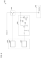
- Fig. 3 is a block diagram of the lamp ECU 400 according to one embodiment.
- the lamp ECU 400 includes a connector 410, a power supply circuit 420, a microcontroller 430, and an output interface circuit 440.
- the connector 410 is connected to a harness (not illustrated) on the vehicle side.
- the connector 410 includes a power supply pin ECUB, a communication pin CAN, and an output pin ECUOUT.
- the power supply pin ECUB receives battery voltage ECUB from the vehicle.
- the communication pin CAN is connected to the vehicle bus 120.
- the output pin ECUOUT is connected to the additional lamp 300.
- the power supply circuit 420 is structured to be switchable between an enabled (on) state and a disabled (off) state.
- An input node of the power supply circuit 420 is connected to the power supply pin ECUB, and an output node thereof is connected to the output pin ECUOUT.
- the power supply circuit 420 In the enabled state, the power supply circuit 420 outputs the power supply voltage V PS from its output node.
- the lamp ECU 400 is switchable between a first mode and a second mode depending on the type of the additional lamp 300 to be combined.
- the microcontroller 430 receives a turn-on/off instruction S1 for the additional lamp 300 via the vehicle bus 120.
- the microcontroller 430 includes a first controller 432 and a second controller 434.
- the first controller 432 controls the enabled and disabled states of the power supply circuit 420 according to the turn-on/off instruction S1 for the additional lamp 300 received via the vehicle bus 120.
- An output node of the output interface circuit 440 is connected to the output pin ECUOUT.
- the output interface circuit 440 changes the state of the output pin ECUOUT into one of two states including a high state and a low state (or a low impedance state and a high impedance state).
- the output interface circuit 440 may be an open drain circuit, an open collector circuit, a CMOS inverter, or the like.
- the second controller 434 controls the output interface circuit 440 according to the turn-on/off instruction S1.
- Fig. 4 is a diagram illustrating a specific configuration example of the lamp ECU 400.
- the power supply circuit 420 includes a switch SW1 provided between the power supply pin ECUB and the output pin ECUOUT.
- the first controller 432 controls on and off of the switch SW1 in the first mode. Specifically, when the turn-on/off instruction S1 instructs the additional lamp 300 to be turned on, the switch SW1 is turned on, and when the turn-on/off instruction S1 instructs the additional lamp 300 to be turned off, the switch SW1 is turned off.
- the configuration of the power supply circuit 420 is not limited to the aforementioned one, and the power supply circuit 420 may be a linear regulator or the like.
- the output interface circuit 440 is an open drain circuit and includes a transistor 442, resistors R11 and R12, an inductor 444, and a varistor 446.
- the second controller 434 controls on and off of the transistor 442 in the second mode. Specifically, the second controller 434 turns on the transistor 442 when the turn-on/off instruction S1 instructs the additional lamp 300 to be turned on. At this time, the output pin ECUOUT becomes low. Also, the second controller 434 turns off the transistor 442 when the turn-on/off instruction S1 instructs the additional lamp 300 to be turned off. At this time, the output pin ECUOUT becomes high (in a high impedance state).
- the varistor 446 is a protective element provided to absorb a surge from the outside.
- a ceramic capacitor or a Zener diode can be used instead of the varistor 446.
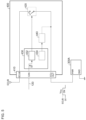
- Fig. 5 is a diagram for explaining connection between the lamp ECU 400 and the additional lamp 300A in Fig. 2(a) .
- the output pin ECUOUT is connected to the power supply pin PWR of the additional lamp 300A.
- the lamp ECU 400 is set to the first mode.
- the first controller 432 controls the power supply circuit 420 according to the turn-on/off instruction S1. When the power supply circuit 420 is enabled, the power supply voltage V PS is supplied to the additional lamp 300A, and the additional lamp 300A is turned on.
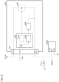
- Fig. 6 is a diagram for explaining connection between the lamp ECU 400 and the additional lamp 300B in Fig. 2(b) .
- the output pin ECUOUT is connected to the control terminal CTRL of the additional lamp 300B.
- the lamp ECU 400 is set to the second mode.
- the second controller 434 controls the output interface circuit 440 according to the turn-on/off instruction S1. When the output interface circuit 440 outputs a low state, the control pin CTRL of the additional lamp 300B becomes low, and the additional lamp 300B is turned on.
- the configuration of the lamp ECU 400 has been described above. According to the lamp ECU 400, by switching the mode of the lamp ECU 400 according to the interface of the additional lamp 300, the function of the output pin ECUOUT in the connector 410 can be switched between two states, and the additional lamps 300A and 300B having different interfaces can be supported.
- the additional lamp 300 is a cornering lamp, but the present invention is not limited thereto, and other lamps may be used.
- the additional lamp 300 may be a turn lamp, a daytime running lamp (DRL), or a clearance lamp.
- DRL daytime running lamp
- the present disclosure relates to a lamp used for a vehicle such as an automobile.
- 100 lamp system 110 vehicle ECU, 120 vehicle bus, 200 head lamp, 210 low beam unit, 220 high beam unit, 300 additional lamp, 400 lamp ECU, 410 connector, 420 power supply circuit, 430 microcontroller, 432 first controller, 434 second controller, 440 output interface circuit
Landscapes
- Engineering & Computer Science (AREA)
- Mechanical Engineering (AREA)
- Lighting Device Outwards From Vehicle And Optical Signal (AREA)
Abstract
Description
- The present disclosure relates to a lamp used for a vehicle such as an automobile.
- In recent years, vehicle lamps have been enhanced in functionality, and a head lamp is provided with a plurality of lamps having different roles, such as a low beam, a high beam, a turn signal lamp, a position lamp, and a daytime running lamp.
- As one of the lamps, there is a cornering lamp (side illumination lamp). The cornering lamp is provided in association with the head lamp and irradiates the turning direction.
- Patent Literature 1:
JP 2014-82147 - The interface of the cornering lamp has several different specifications. Conventionally, a lamp electronic control unit (ECU) incorporated in the head lamp has been designed for each specification of the cornering lamp. That is, an automobile manufacturer needs to select and design a different lamp ECU for each specification of the cornering lamp.
- The present disclosure has been made in view of such a problem, and an exemplary object of an aspect of the present disclosure is to provide a lamp ECU that can support an additional lamp having a different interface.
- An aspect of the present disclosure relates to a lamp electronic control unit capable of controlling an additional lamp. A lamp electronic control unit includes a connector including a power supply pin that receives battery voltage from a vehicle, a communication pin connected to a vehicle bus, and an output pin to be connected to the additional lamp, a power supply circuit including an output node connected to the output pin and structured to output power supply voltage from the output node in an enabled state, a first controller structured to control, in a first mode, the enabled state and a disabled state of the power supply circuit according to a turn-on/off instruction for the additional lamp received via the vehicle bus, an output interface circuit including an output node connected to the output pin, and a second controller structured to control, in a second mode, the output interface circuit according to the turn-on/off instruction.
- Note that freely-selected combination of the above components, and mutual substitution of the components and expressions among a method, an apparatus, a system, and the like are valid as aspects of the present invention or the present disclosure. Furthermore, the description of this section (SOLUTION TO PROBLEM) does not describe all essential features of the present invention, and thus subcombinations of these features described may also be the present invention.
- According to an aspect of the present disclosure, an additional lamp having a different interface can be controlled.
-
- [
Fig. 1] Fig. 1 is a block diagram of a lamp system according to one embodiment. - [
Fig. 2] Figs. 2(a) and 2(b) are views illustrating additional lamps having different interfaces. - [
Fig. 3] Fig. 3 is a block diagram of a lamp ECU according to one embodiment. - [
Fig. 4] Fig. 4 is a diagram illustrating a specific configuration example of the lamp ECU. - [
Fig. 5] Fig. 5 is a diagram for explaining connection between the lamp ECU and the additional lamp inFig. 2(a) . - [
Fig. 6] Fig. 6 is a diagram for explaining connection between the lamp ECU and the additional lamp inFig. 2(b) . - An overview of some example embodiments of the present disclosure will be described. This overview describes some concepts of one or more embodiments in a simplified manner for the purpose of basic understanding of the embodiments before providing the detailed description that follows, and does not limit the scope of the invention or disclosure. This overview is not a comprehensive overview of all possible embodiments, and is not intended to identify key elements of all embodiments or define the scope of some or all aspects. For convenience, "one embodiment" may be used to refer to one embodiment (example or modification) or a plurality of embodiments (examples or modifications) disclosed in the present specification.
- A lamp electronic control unit according to one embodiment can control an additional lamp. The lamp electronic control unit includes a connector including a power supply pin that receives battery voltage from a vehicle, a communication pin connected to a vehicle bus, and an output pin to be connected to the additional lamp, a power supply circuit including an output node connected to the output pin and structured to output power supply voltage from the output node in an enabled state, a first controller structured to control, in a first mode, the enabled state and a disabled state of the power supply circuit according to a turn-on/off instruction for the additional lamp received via the vehicle bus, an output interface circuit including an output node connected to the output pin, and a second controller structured to control, in a second mode, the output interface circuit according to the turn-on/off instruction.
- According to this configuration, by switching the mode of the lamp electronic control unit according to the interface of the additional lamp, the function of the output pin in the connector can be switched between two states. That is, the additional lamp having different interfaces can be supported. In addition, since two pins having different functions are integrated into one pin, an increase in cost can be avoided.
- In one embodiment, the power supply circuit may include a switch provided between the power supply pin and the output pin. The first controller may control on and off of the switch in the first mode.
- In one embodiment, the additional lamp may be a cornering lamp.
- In one embodiment, the additional lamp may be a turn lamp.
- In one embodiment, the additional lamp may be a daytime running light.
- In one embodiment, the additional lamp may be a clearance lamp.
- Hereinbelow, preferred embodiments will be described with reference to the drawings. Similar or identical components, members, and processes illustrated in the respective figures are labeled with the same reference signs, and description of the duplicate components is omitted as needed. Further, the embodiments are not intended to limit the disclosure and the invention, but are merely examples, and all features described in the embodiments and combinations thereof are not necessarily essential to the disclosure and the invention.
- In the present specification, "a state in which a member A is connected to a member B" includes not only a case where the member A and the member B are physically and directly connected to each other, but also a case where the member A and the member B are indirectly connected to each other via another member which does not substantially affect an electric connection state between the member A and the member B or which does not impair a function or an effect exhibited by coupling between the member A and the member B.
- Similarly, "a state in which a member C is connected (provided) between the member A and the member B" includes not only a case where the member A and the member C, or the member B and the member C are directly connected to each other, but also a case where the members are indirectly connected to each other via another member which does not substantially affect an electric connection state between the members or which does not impair a function or an effect exhibited by the connection between the members.
- In addition, in the present specification, an electric signal such as a voltage signal or a current signal, or a sign attached to a circuit element such as a resistor, a capacitor, or an inductor represents a voltage value, a current value, or a circuit constant (a resistance value, a capacitance value, or an inductance) thereof as necessary.
-
Fig. 1 is a block diagram of alamp system 100 according to one embodiment. Thelamp system 100 includes a vehicle electronic control unit (ECU) 110, ahead lamp 200, and anadditional lamp 300. - The
head lamp 200 includes alow beam unit 210, ahigh beam unit 220, and alamp ECU 400 that controls thelow beam unit 210 and thehigh beam unit 220. Thelow beam unit 210 includes a light emitting element such as an LED, a driver module that drives the LED, and the like. Thehigh beam unit 220 also has a similar configuration. - The vehicle ECU 110 and the
head lamp 200 are connected via avehicle bus 120 such as a controller area network (CAN) or a local interconnect network (LIN). The vehicle ECU 110 transmits a turn-on/off instruction for thelow beam unit 210 and thehigh beam unit 220 to the lamp ECU 400 via thevehicle bus 120. The lamp ECU 400 controls the turn-on/off operation of thelow beam unit 210 and thehigh beam unit 220 according to the instruction from the vehicle ECU 110. - The
additional lamp 300 is incorporated in a housing independent of thehead lamp 200. For example, thehead lamp 200 is a cornering lamp, and is attached to a bumper or the like. - The turn-on/off instruction for the
additional lamp 300 is not directly transmitted from thevehicle ECU 110 to theadditional lamp 300, but is transmitted via thehead lamp 200. That is, thelamp ECU 400 of thehead lamp 200 is structured to receive the turn-on/off instruction for theadditional lamp 300 and control theadditional lamp 300 according to the turn-on/off instruction. - In an actual vehicle, a set including the
head lamp 200 and theadditional lamp 300 is provided on each of the right and left sides. The entire configuration of thelamp system 100 has been described above. - Next, the interface of the
additional lamp 300 will be described. -
Figs. 2(a) and 2(b) are diagrams illustrating theadditional lamps 300 having different interfaces. Anadditional lamp 300A inFig. 2(a) has a power supply terminal PWR and a ground terminal GND. The ground terminal GND is grounded. The power supply terminal PWR is connected to thelamp ECU 400 of thehead lamp 200. Theadditional lamp 300A is turned on when power supply voltage VPS is supplied to the power supply terminal PWR, and is turned off when the power supply voltage VPS is cut off. - An
additional lamp 300B inFig. 2(b) includes a control terminal CTRL, a battery terminal BAT, and a ground terminal GND. Power supply voltage (battery voltage) IGR from the vehicle is supplied to the battery terminal VBAT. The ground terminal GND is grounded. The control terminal CTRL is a terminal for receiving a control signal VCTRL from thehead lamp 200. The control signal VCTRL is a digital binary signal and has, for example, two states including a high state and a low state. Theadditional lamp 300B is turned on when the control terminal CTRL is at a first level (for example, a low state), and is turned off when the control terminal CTRL is at a second level (for example, a high state). - Next, the
lamp ECU 400 connectable to theadditional lamp Fig. 2(a) or 2(b) will be described. -
Fig. 3 is a block diagram of thelamp ECU 400 according to one embodiment. - The
lamp ECU 400 includes aconnector 410, apower supply circuit 420, amicrocontroller 430, and anoutput interface circuit 440. - The
connector 410 is connected to a harness (not illustrated) on the vehicle side. Theconnector 410 includes a power supply pin ECUB, a communication pin CAN, and an output pin ECUOUT. The power supply pin ECUB receives battery voltage ECUB from the vehicle. The communication pin CAN is connected to thevehicle bus 120. The output pin ECUOUT is connected to theadditional lamp 300. - The
power supply circuit 420 is structured to be switchable between an enabled (on) state and a disabled (off) state. An input node of thepower supply circuit 420 is connected to the power supply pin ECUB, and an output node thereof is connected to the output pin ECUOUT. In the enabled state, thepower supply circuit 420 outputs the power supply voltage VPS from its output node. - The
lamp ECU 400 is switchable between a first mode and a second mode depending on the type of theadditional lamp 300 to be combined. - The
microcontroller 430 receives a turn-on/off instruction S1 for theadditional lamp 300 via thevehicle bus 120. Themicrocontroller 430 includes afirst controller 432 and asecond controller 434. - In the first mode, the
first controller 432 controls the enabled and disabled states of thepower supply circuit 420 according to the turn-on/off instruction S1 for theadditional lamp 300 received via thevehicle bus 120. - An output node of the
output interface circuit 440 is connected to the output pin ECUOUT. Theoutput interface circuit 440 changes the state of the output pin ECUOUT into one of two states including a high state and a low state (or a low impedance state and a high impedance state). As described below, theoutput interface circuit 440 may be an open drain circuit, an open collector circuit, a CMOS inverter, or the like. - In the second mode, the
second controller 434 controls theoutput interface circuit 440 according to the turn-on/off instruction S1. -
Fig. 4 is a diagram illustrating a specific configuration example of thelamp ECU 400. Thepower supply circuit 420 includes a switch SW1 provided between the power supply pin ECUB and the output pin ECUOUT. Thefirst controller 432 controls on and off of the switch SW1 in the first mode. Specifically, when the turn-on/off instruction S1 instructs theadditional lamp 300 to be turned on, the switch SW1 is turned on, and when the turn-on/off instruction S1 instructs theadditional lamp 300 to be turned off, the switch SW1 is turned off. - Note that the configuration of the
power supply circuit 420 is not limited to the aforementioned one, and thepower supply circuit 420 may be a linear regulator or the like. - The
output interface circuit 440 is an open drain circuit and includes atransistor 442, resistors R11 and R12, aninductor 444, and avaristor 446. - The
second controller 434 controls on and off of thetransistor 442 in the second mode. Specifically, thesecond controller 434 turns on thetransistor 442 when the turn-on/off instruction S1 instructs theadditional lamp 300 to be turned on. At this time, the output pin ECUOUT becomes low. Also, thesecond controller 434 turns off thetransistor 442 when the turn-on/off instruction S1 instructs theadditional lamp 300 to be turned off. At this time, the output pin ECUOUT becomes high (in a high impedance state). - The
varistor 446 is a protective element provided to absorb a surge from the outside. As the protective element, a ceramic capacitor or a Zener diode can be used instead of thevaristor 446. - The configuration example of the
lamp ECU 400 has been described above. -
Fig. 5 is a diagram for explaining connection between thelamp ECU 400 and theadditional lamp 300A inFig. 2(a) . The output pin ECUOUT is connected to the power supply pin PWR of theadditional lamp 300A. Thelamp ECU 400 is set to the first mode. Thefirst controller 432 controls thepower supply circuit 420 according to the turn-on/off instruction S1. When thepower supply circuit 420 is enabled, the power supply voltage VPS is supplied to theadditional lamp 300A, and theadditional lamp 300A is turned on. -
Fig. 6 is a diagram for explaining connection between thelamp ECU 400 and theadditional lamp 300B inFig. 2(b) . The output pin ECUOUT is connected to the control terminal CTRL of theadditional lamp 300B. Thelamp ECU 400 is set to the second mode. Thesecond controller 434 controls theoutput interface circuit 440 according to the turn-on/off instruction S1. When theoutput interface circuit 440 outputs a low state, the control pin CTRL of theadditional lamp 300B becomes low, and theadditional lamp 300B is turned on. - The configuration of the
lamp ECU 400 has been described above. According to thelamp ECU 400, by switching the mode of thelamp ECU 400 according to the interface of theadditional lamp 300, the function of the output pin ECUOUT in theconnector 410 can be switched between two states, and theadditional lamps - Since two pins having different functions are integrated and assembled into one output pin ECUOUT, an increase in cost can be avoided.
- It is understood by those skilled in the art that the above-described embodiments are examples, and various modifications can be made to combinations of the respective components and the respective processes. Hereinbelow, such modifications will be described.
- In the aforementioned embodiment, the
additional lamp 300 is a cornering lamp, but the present invention is not limited thereto, and other lamps may be used. For example, theadditional lamp 300 may be a turn lamp, a daytime running lamp (DRL), or a clearance lamp. - Although the embodiment according to the present disclosure has been described using specific terms, this description is merely an example for facilitating understanding, and does not limit the present disclosure or the claims. The scope of the present invention is defined by the claims, and therefore, embodiments, examples, and modifications that are not described herein are also included in the scope of the present invention.
- The present disclosure relates to a lamp used for a vehicle such as an automobile.
- 100 lamp system, 110 vehicle ECU, 120 vehicle bus, 200 head lamp, 210 low beam unit, 220 high beam unit, 300 additional lamp, 400 lamp ECU, 410 connector, 420 power supply circuit, 430 microcontroller, 432 first controller, 434 second controller, 440 output interface circuit
Claims (4)
- A lamp electronic control unit capable of controlling an additional lamp, the lamp electronic control unit comprising:a connector including a power supply pin that receives battery voltage from a vehicle, a communication pin connected to a vehicle bus, and an output pin to be connected to the additional lamp;a power supply circuit including an output node connected to the output pin and structured to output power supply voltage from the output node in an enabled state;a first controller structured to control, in a first mode, the enabled state and a disabled state of the power supply circuit according to a turn-on/off instruction for the additional lamp received via the vehicle bus;an output interface circuit including an output node connected to the output pin; anda second controller structured to control, in a second mode, the output interface circuit according to the turn-on/off instruction.
- The lamp electronic control unit according to claim 1, whereinthe power supply circuit includes a switch provided between the power supply pin and the output pin, andthe first controller controls on and off of the switch in the first mode.
- The lamp electronic control unit according to claim 1 or 2, wherein the output interface circuit is an open drain circuit.
- The lamp electronic control unit according to claim 1 or 2, wherein the additional lamp is a cornering lamp.
Applications Claiming Priority (2)
| Application Number | Priority Date | Filing Date | Title |
|---|---|---|---|
| JP2022039624 | 2022-03-14 | ||
| PCT/JP2023/009620 WO2023176775A1 (en) | 2022-03-14 | 2023-03-13 | Lamp electronic control unit |
Publications (2)
| Publication Number | Publication Date |
|---|---|
| EP4494941A1 true EP4494941A1 (en) | 2025-01-22 |
| EP4494941A4 EP4494941A4 (en) | 2025-07-16 |
Family
ID=88023779
Family Applications (1)
| Application Number | Title | Priority Date | Filing Date |
|---|---|---|---|
| EP23770730.2A Pending EP4494941A4 (en) | 2022-03-14 | 2023-03-13 | ELECTRONIC LAMP CONTROL UNIT |
Country Status (5)
| Country | Link |
|---|---|
| US (1) | US20250008628A1 (en) |
| EP (1) | EP4494941A4 (en) |
| JP (1) | JPWO2023176775A1 (en) |
| CN (1) | CN118871321A (en) |
| WO (1) | WO2023176775A1 (en) |
Families Citing this family (1)
| Publication number | Priority date | Publication date | Assignee | Title |
|---|---|---|---|---|
| JP2025062169A (en) * | 2023-10-02 | 2025-04-14 | 株式会社小糸製作所 | Lighting circuit and lighting device |
Family Cites Families (4)
| Publication number | Priority date | Publication date | Assignee | Title |
|---|---|---|---|---|
| JP6073637B2 (en) | 2012-10-18 | 2017-02-01 | 株式会社小糸製作所 | Electronic unit |
| JP5749238B2 (en) * | 2012-11-09 | 2015-07-15 | 古河電気工業株式会社 | Lamp control unit for vehicle |
| WO2017217318A1 (en) * | 2016-06-13 | 2017-12-21 | 株式会社小糸製作所 | Load driving device, and vehicular lighting fixture |
| KR101850324B1 (en) * | 2016-08-29 | 2018-04-19 | 엘지전자 주식회사 | Lamp and Autonomous Vehicle |
-
2023
- 2023-03-13 CN CN202380027813.7A patent/CN118871321A/en active Pending
- 2023-03-13 WO PCT/JP2023/009620 patent/WO2023176775A1/en not_active Ceased
- 2023-03-13 JP JP2024508155A patent/JPWO2023176775A1/ja active Pending
- 2023-03-13 EP EP23770730.2A patent/EP4494941A4/en active Pending
-
2024
- 2024-09-13 US US18/884,211 patent/US20250008628A1/en active Pending
Also Published As
| Publication number | Publication date |
|---|---|
| CN118871321A (en) | 2024-10-29 |
| WO2023176775A1 (en) | 2023-09-21 |
| JPWO2023176775A1 (en) | 2023-09-21 |
| EP4494941A4 (en) | 2025-07-16 |
| US20250008628A1 (en) | 2025-01-02 |
Similar Documents
| Publication | Publication Date | Title |
|---|---|---|
| CN100423148C (en) | Modular switch and control system for use in a motor vehicle | |
| US6982648B2 (en) | Lighting or indicating light unit for a vehicle and lighting or indicating system equipped with at least one such light unit | |
| EP3785992B1 (en) | Rear turn lamp | |
| US10124721B2 (en) | System to augment automotive factory lights with warning light function | |
| JP2006103404A (en) | Lighting control circuit for vehicular lamp | |
| US20250008628A1 (en) | Lamp electronic control unit | |
| KR101209799B1 (en) | Switch identification system for vehicle | |
| KR19990083237A (en) | Electronic blinker | |
| KR20190080460A (en) | LED driving apparatus for vehicle lamp | |
| CN111381527B (en) | Vehicle load control circuit and method | |
| CN103072532A (en) | Load control device | |
| US10492281B2 (en) | Selective power supply device for incandescent lamp or light-emitting diode | |
| KR20010051048A (en) | Electronic driver circuit for use in an electronic system, and method | |
| US11407313B2 (en) | Power supply circuit | |
| EP4668679A1 (en) | System and method for controlling vehicle lamps | |
| CN108366465B (en) | Light source control circuit and lighting device | |
| CN224225013U (en) | Combined switch module, vehicle operation module and vehicle | |
| CN224152886U (en) | A self-defining button controlling means and general steering wheel for car steering wheel | |
| JP4983242B2 (en) | Vehicle wiring system | |
| US20230202384A1 (en) | Device for controlling an auxiliary light mounted to a vehicle | |
| EP4613559A1 (en) | Rear turn lamp | |
| EP4601909A1 (en) | Vehicle driving light with internal voltage sensor receiving hi-beam signal | |
| WO2025015439A1 (en) | A flexible dc-dc converter | |
| CN217088216U (en) | N-1 short circuit protection module of LED with net structure | |
| KR101360687B1 (en) | Switch identification system for vehicle |
Legal Events
| Date | Code | Title | Description |
|---|---|---|---|
| STAA | Information on the status of an ep patent application or granted ep patent |
Free format text: STATUS: THE INTERNATIONAL PUBLICATION HAS BEEN MADE |
|
| PUAI | Public reference made under article 153(3) epc to a published international application that has entered the european phase |
Free format text: ORIGINAL CODE: 0009012 |
|
| STAA | Information on the status of an ep patent application or granted ep patent |
Free format text: STATUS: REQUEST FOR EXAMINATION WAS MADE |
|
| 17P | Request for examination filed |
Effective date: 20240903 |
|
| AK | Designated contracting states |
Kind code of ref document: A1 Designated state(s): AL AT BE BG CH CY CZ DE DK EE ES FI FR GB GR HR HU IE IS IT LI LT LU LV MC ME MK MT NL NO PL PT RO RS SE SI SK SM TR |
|
| DAV | Request for validation of the european patent (deleted) | ||
| DAX | Request for extension of the european patent (deleted) | ||
| A4 | Supplementary search report drawn up and despatched |
Effective date: 20250617 |
|
| RIC1 | Information provided on ipc code assigned before grant |
Ipc: B60Q 1/00 20060101AFI20250611BHEP Ipc: B60Q 1/04 20060101ALI20250611BHEP Ipc: B60Q 1/24 20060101ALI20250611BHEP Ipc: H05B 45/30 20200101ALI20250611BHEP Ipc: B60Q 1/18 20060101ALI20250611BHEP Ipc: H05B 47/17 20200101ALI20250611BHEP Ipc: B60Q 1/12 20060101ALI20250611BHEP Ipc: B60Q 1/14 20060101ALI20250611BHEP Ipc: B60Q 1/38 20060101ALI20250611BHEP |