EP4494934A2 - Long rail assembly with internal power driving system - Google Patents
Long rail assembly with internal power driving system Download PDFInfo
- Publication number
- EP4494934A2 EP4494934A2 EP24209245.0A EP24209245A EP4494934A2 EP 4494934 A2 EP4494934 A2 EP 4494934A2 EP 24209245 A EP24209245 A EP 24209245A EP 4494934 A2 EP4494934 A2 EP 4494934A2
- Authority
- EP
- European Patent Office
- Prior art keywords
- rail assembly
- long rail
- lower channel
- channel
- upper channel
- Prior art date
- Legal status (The legal status is an assumption and is not a legal conclusion. Google has not performed a legal analysis and makes no representation as to the accuracy of the status listed.)
- Granted
Links
Images


Classifications
-
- B—PERFORMING OPERATIONS; TRANSPORTING
- B60—VEHICLES IN GENERAL
- B60N—SEATS SPECIALLY ADAPTED FOR VEHICLES; VEHICLE PASSENGER ACCOMMODATION NOT OTHERWISE PROVIDED FOR
- B60N2/00—Seats specially adapted for vehicles; Arrangement or mounting of seats in vehicles
- B60N2/02—Seats specially adapted for vehicles; Arrangement or mounting of seats in vehicles the seat or part thereof being movable, e.g. adjustable
- B60N2/04—Seats specially adapted for vehicles; Arrangement or mounting of seats in vehicles the seat or part thereof being movable, e.g. adjustable the whole seat being movable
- B60N2/06—Seats specially adapted for vehicles; Arrangement or mounting of seats in vehicles the seat or part thereof being movable, e.g. adjustable the whole seat being movable slidable
-
- B—PERFORMING OPERATIONS; TRANSPORTING
- B60—VEHICLES IN GENERAL
- B60N—SEATS SPECIALLY ADAPTED FOR VEHICLES; VEHICLE PASSENGER ACCOMMODATION NOT OTHERWISE PROVIDED FOR
- B60N2/00—Seats specially adapted for vehicles; Arrangement or mounting of seats in vehicles
- B60N2/02—Seats specially adapted for vehicles; Arrangement or mounting of seats in vehicles the seat or part thereof being movable, e.g. adjustable
- B60N2/0224—Non-manual adjustments, e.g. with electrical operation
- B60N2/02246—Electric motors therefor
-
- B—PERFORMING OPERATIONS; TRANSPORTING
- B60—VEHICLES IN GENERAL
- B60N—SEATS SPECIALLY ADAPTED FOR VEHICLES; VEHICLE PASSENGER ACCOMMODATION NOT OTHERWISE PROVIDED FOR
- B60N2/00—Seats specially adapted for vehicles; Arrangement or mounting of seats in vehicles
- B60N2/02—Seats specially adapted for vehicles; Arrangement or mounting of seats in vehicles the seat or part thereof being movable, e.g. adjustable
- B60N2/04—Seats specially adapted for vehicles; Arrangement or mounting of seats in vehicles the seat or part thereof being movable, e.g. adjustable the whole seat being movable
- B60N2/06—Seats specially adapted for vehicles; Arrangement or mounting of seats in vehicles the seat or part thereof being movable, e.g. adjustable the whole seat being movable slidable
- B60N2/07—Slide construction
-
- B—PERFORMING OPERATIONS; TRANSPORTING
- B60—VEHICLES IN GENERAL
- B60N—SEATS SPECIALLY ADAPTED FOR VEHICLES; VEHICLE PASSENGER ACCOMMODATION NOT OTHERWISE PROVIDED FOR
- B60N2/00—Seats specially adapted for vehicles; Arrangement or mounting of seats in vehicles
- B60N2/02—Seats specially adapted for vehicles; Arrangement or mounting of seats in vehicles the seat or part thereof being movable, e.g. adjustable
- B60N2/04—Seats specially adapted for vehicles; Arrangement or mounting of seats in vehicles the seat or part thereof being movable, e.g. adjustable the whole seat being movable
- B60N2/06—Seats specially adapted for vehicles; Arrangement or mounting of seats in vehicles the seat or part thereof being movable, e.g. adjustable the whole seat being movable slidable
- B60N2/07—Slide construction
- B60N2/0702—Slide construction characterised by its cross-section
- B60N2/0705—Slide construction characterised by its cross-section omega-shaped
-
- B—PERFORMING OPERATIONS; TRANSPORTING
- B60—VEHICLES IN GENERAL
- B60N—SEATS SPECIALLY ADAPTED FOR VEHICLES; VEHICLE PASSENGER ACCOMMODATION NOT OTHERWISE PROVIDED FOR
- B60N2/00—Seats specially adapted for vehicles; Arrangement or mounting of seats in vehicles
- B60N2/02—Seats specially adapted for vehicles; Arrangement or mounting of seats in vehicles the seat or part thereof being movable, e.g. adjustable
- B60N2/04—Seats specially adapted for vehicles; Arrangement or mounting of seats in vehicles the seat or part thereof being movable, e.g. adjustable the whole seat being movable
- B60N2/06—Seats specially adapted for vehicles; Arrangement or mounting of seats in vehicles the seat or part thereof being movable, e.g. adjustable the whole seat being movable slidable
- B60N2/07—Slide construction
- B60N2/0702—Slide construction characterised by its cross-section
- B60N2/0715—C or U-shaped
-
- B—PERFORMING OPERATIONS; TRANSPORTING
- B60—VEHICLES IN GENERAL
- B60N—SEATS SPECIALLY ADAPTED FOR VEHICLES; VEHICLE PASSENGER ACCOMMODATION NOT OTHERWISE PROVIDED FOR
- B60N2/00—Seats specially adapted for vehicles; Arrangement or mounting of seats in vehicles
- B60N2/02—Seats specially adapted for vehicles; Arrangement or mounting of seats in vehicles the seat or part thereof being movable, e.g. adjustable
- B60N2/0224—Non-manual adjustments, e.g. with electrical operation
- B60N2/02246—Electric motors therefor
- B60N2/02253—Electric motors therefor characterised by the transmission between the electric motor and the seat or seat parts
Definitions
- the present invention relates to a long rail assembly that adjusts a seat assembly's position within a vehicle.
- adjustable seat assemblies in vehicles incorporate various parts that take the mechanical energy generated by a motor and use it to move the seat.
- These systems include gearboxes, racks, pinions and other mechanical parts that are often integrated with the floor of the vehicle's interior.
- dirt or debris brought into the vehicle collect on the floor and within these systems. The buildup of dirt and debris can cause these systems to become less efficient or simply stop working altogether. It is desirable to have a system capable of power adjustment wherein the mechanical parts are mostly sheltered from this eventual buildup.
- a long rail assembly for use in a vehicle comprising a lower channel, an inverted U-shaped upper channel, a gearbox, a rack, a pinion, a drive shaft, and a motor.
- the lower channel is adapted to extend longitudinally along a floor of the vehicle.
- the upper channel is slidably coupled to the lower channel.
- the gearbox is fixedly secured to and housed within the upper channel.
- the rack is fixedly coupled to the lower channel and includes gear teeth extending along the rack in a longitudinal direction.
- the pinion is meshingly engaged with the gear teeth.
- the drive shaft operatively couples the gearbox to the pinion.
- the motor is operatively coupled to the gearbox to power drive the upper channel along the lower channel.
- a long rail assembly for use in a vehicle comprising a lower channel, an upper channel, a plurality of gears, a rack, a pinion, a drive shaft, and a motor.
- the lower channel is adapted to extend longitudinally along a floor of the vehicle.
- the lower channel includes opposing sidewalls, a bottom wall and a top wall extending between the opposing sidewalls.
- the top wall has an elongated opening extending in a longitudinal direction.
- the upper channel is slidably coupled to the lower channel.
- the plurality of gears is operatively coupled to the upper channel.
- the rack is fixedly coupled to the top wall of the lower channel and includes gear teeth extending along the rack in a longitudinal direction.
- the gear teeth are oriented toward the bottom wall of the lower channel.
- the pinion is meshingly engaged with the gear teeth.
- the drive shaft operatively couples the plurality of gears to the pinion.
- the motor is operatively coupled to the plurality of gears to power drive the upper channel along the lower channel.
- FIG. 1 illustrates an interior 11 of a vehicle with a plurality of long rail assemblies 10 configured to reposition a plurality of seat assemblies 12 along a floor 30 of the vehicle according to embodiments described herein.
- Each seat assembly 12 includes a seat cushion 16 and a seat back 14 operatively coupled to the seat cushion 16 for supporting a seat occupant in a generally upright seating position.
- Each seat assembly 12 also includes a mounting structure 18 that supports the seat cushion 16 above the vehicle floor 30.
- the mounting structure 18 includes a pair of rear legs 22, 24, and may also include front legs 20.
- Each long rail assembly 10 includes a pair of U-shaped lower channels 26, 26' adapted to be fixedly secured to the vehicle floor 30 and a plurality of rail drive assemblies 28 that are configured to travel along the U-shaped lower channels 26, 26'.
- the mounting structure 18 of the seat assembly 12 is adapted to be fixedly secured to the rail drive assembly 28.
- the seat assembly 12 may be adjusted among a plurality of fore/aft seating positions along the vehicle floor 30. For example, the seat assembly 12 may be repositioned from a first seat location 31 to a second seat location 32 by sliding the rail drive assembly 28 that is secured to the seat assembly 12 along the U-shaped lower channels 26, 26'.
- the U-shaped lower channel 26 includes opposing sidewalls 40, 41 a top wall 42 and a bottom wall 44 extending between the opposing sidewalls 40, 41.
- the top wall 42 includes an elongated opening 46 extending in a longitudinal direction.
- Each sidewall 40, 41 of the lower channel 26 is bent into a C-shaped cross-section in profile to form tracks 48, 49 respectively.
- the bottom wall 44 of the lower channel 26 is configured to be fixedly attached to the vehicle floor 30.
- the rail drive assembly 28 includes an inverted U-shaped upper channel 58 slidably coupled to the lower channel 26.
- the upper channel 58 includes a pair of opposing sidewalls 80, 81 and a top wall 82 extending therebetween.
- the rail drive assembly 28 also includes stability rollers 64 projecting from the sidewalls 80, 81 of the upper channel 58 and a torsion spring 92 to bias the stability rollers 64 against the respective sidewalls 40, 41 of the lower channel 26.
- the stability rollers 64 may project from the sidewalls 80, 81 at an angle to counteract both vertical and lateral tolerance variations between the upper channel 58 and the lower channel 26 within the long rail assembly 10.
- the rail drive assembly 28 further includes front and rear axles 60, 62 operatively coupled to the side walls 80, 81 of the upper channel 58 and opposing wheels 110 that are coupled to the ends of each axle 60, 62.
- the wheels 110 are configured to travel along the tracks 48, 49 of the lower channel 26.
- the rail drive assembly 28 further includes a gearbox 66 fixedly secured to and housed within the upper channel 58.
- the gearbox 66 includes a vertically oriented worm gear 150 meshingly engaged with a worm wheel 152 within a gearbox housing 120.
- a mounting structure 122 is fixedly attached to an outer surface 126 of the gearbox housing 120 and mounts the gearbox 66 to the top wall 82 of the upper channel 58 via bolts, rivets, fasteners, or welds.
- the side walls 80, 81 of the upper channel 58 may extend above the height of the top wall 42 of the lower channel 26.
- the taller upper channel 58 creates enough space for a horizontally oriented worm gear 151.
- the horizontally oriented worm gear 151 is meshingly engaged with the worm wheel 152 within the gearbox housing 120.
- the horizontal orientation of the worm gear 151 allows for alternative packaging arrangements as will be discussed further hereinbelow.
- the rail drive assembly 28 also includes a drive shaft 68 and a pinion 70.
- a first end 130 of the drive shaft 68 is fixedly coupled to the worm wheel 152, and an opposite second end 132 of the drive shaft 68 is fixedly coupled to the pinion 70.
- the drive shaft 68 extends out of the gearbox 66 through an opening 134 in the sidewall 80 of the upper channel 58
- the long rail assembly 10 further includes a rack 160 fixedly coupled to the top wall 42 of the lower channel 26.
- the rack 160 includes a plurality of generally equally spaced apart gear teeth 162 extending along the length of the rack 160 in a longitudinal direction.
- the gear teeth 162 are oriented towards or facing the bottom wall 44 of the lower channel 26.
- the pinion 70 is oriented in a vertical position to meshingly engage with the gear teeth 162 of the rack 160.
- the gearbox 66, the rack 160 and pinion 70 are packaged inside the long rail assembly 10 to conceal it from any dirt and debris that may accumulate on the vehicle floor 30.
- the gearbox 66 is mounted within the upper channel 58, the upper channel 58 will prevent any dirt or debris from falling directly into gearbox 66.
- the rack 160 is mounted within the lower channel 26 and the gear teeth 162 of the rack 160 are facing downward, any dirt or debris that enters the lower channel 26 will not settle on the gear teeth 162.
- the gearbox 66, the rack 160 and the pinion 70 are elevated above the bottom wall 44 of the lower channel 26, they are not likely to collect any dirt or debris that may accumulate in the lower channel 26.
- the long rail assembly 10 further includes an electric motor 170.
- a flexible shaft 180 operatively couples an output shaft 172 of the motor 170 to the worm gear 150.
- the flexible shaft 180 extends from the output shaft 172 through an opening 182 in the top wall 82 of the upper channel 58 and an opening 184 in the gearbox 66 to the vertically oriented worm gear 150.
- the flexible shaft 180 extends from the output shaft 172 through an opening 185 in either of the side walls 80, 81 of the upper channel 58 and an opening 187 in the gearbox 66 to the horizontally oriented worm gear 151. This alternative arrangement eliminates some of the bends in the flexible shaft 180 thereby increasing the efficiency and torque of the motor 170.
- the output shaft 172 of the motor 170 can extend directly to the horizontally oriented worm gear 151 through the opening 185 in the upper channel and the opening 187 in the gearbox 66 eliminating the need for the flexible shaft 180 altogether.
- the motor 170 may be mounted anywhere on the seat assembly 12.
- the motor 170 may be mounted to the bottom of the seat cushion 16.
- the motor 170 preferably includes two output shafts 172 to allow a single motor 170 to provide power to both rail drive assemblies 28, 28'. Alternatively, each rail drive assembly 28, 28' may be powered by separate motors 170.
- the output shaft 172 rotates the flexible shaft 180 causing the worm gear 150, 151 to rotate.
- Rotation of the worm gear 150, 151 is transferred to the worm wheel 152 through their meshing engagement.
- the drive shaft 68 transfers the rotation of the worm wheel 152 to the pinion 70.
- the rotation of the pinion 70 along the rack 160 transposes the rail drive assembly 28 along the lower channel 26, thereby moving the seat assembly 12 along the long rail assembly 10 in a first direction.
- Reversing the rotational direction of the motor 170 results in the pinion 70 rotating in an opposite direction along the rack 160, thus moving the rail drive assembly 28 and the corresponding seat assembly 12 along the lower channel 26 in an opposite direction.
- pulse width modulation of the motor 170 may provide a more comfortable adjustment speed when the seat assembly 12 is occupied, and a quicker adjustment speed when the seat assembly 12 is unoccupied.
Landscapes
- Engineering & Computer Science (AREA)
- Aviation & Aerospace Engineering (AREA)
- Transportation (AREA)
- Mechanical Engineering (AREA)
- Seats For Vehicles (AREA)
- Transmission Devices (AREA)
Abstract
Description
- This application claims priority to and all the benefits of
U.S. Provisional Patent Application No. 62/818,370, filed March 14, 2019 - The present invention relates to a long rail assembly that adjusts a seat assembly's position within a vehicle.
- Many vehicles today have systems that give seats the capability of power adjustment. For example, adjustable seat assemblies in vehicles incorporate various parts that take the mechanical energy generated by a motor and use it to move the seat. These systems include gearboxes, racks, pinions and other mechanical parts that are often integrated with the floor of the vehicle's interior. Often times dirt or debris brought into the vehicle collect on the floor and within these systems. The buildup of dirt and debris can cause these systems to become less efficient or simply stop working altogether. It is desirable to have a system capable of power adjustment wherein the mechanical parts are mostly sheltered from this eventual buildup.
- According to one embodiment, there is provided a long rail assembly for use in a vehicle comprising a lower channel, an inverted U-shaped upper channel, a gearbox, a rack, a pinion, a drive shaft, and a motor. The lower channel is adapted to extend longitudinally along a floor of the vehicle. The upper channel is slidably coupled to the lower channel. The gearbox is fixedly secured to and housed within the upper channel. The rack is fixedly coupled to the lower channel and includes gear teeth extending along the rack in a longitudinal direction. The pinion is meshingly engaged with the gear teeth. The drive shaft operatively couples the gearbox to the pinion. The motor is operatively coupled to the gearbox to power drive the upper channel along the lower channel.
- According to another embodiment, there is provided a long rail assembly for use in a vehicle comprising a lower channel, an upper channel, a plurality of gears, a rack, a pinion, a drive shaft, and a motor. The lower channel is adapted to extend longitudinally along a floor of the vehicle. The lower channel includes opposing sidewalls, a bottom wall and a top wall extending between the opposing sidewalls. The top wall has an elongated opening extending in a longitudinal direction. The upper channel is slidably coupled to the lower channel. The plurality of gears is operatively coupled to the upper channel. The rack is fixedly coupled to the top wall of the lower channel and includes gear teeth extending along the rack in a longitudinal direction. The gear teeth are oriented toward the bottom wall of the lower channel. The pinion is meshingly engaged with the gear teeth. The drive shaft operatively couples the plurality of gears to the pinion. Finally, the motor is operatively coupled to the plurality of gears to power drive the upper channel along the lower channel.
- The following is a numbered list of aspects of the invention:
- 1. A long rail assembly for use in a vehicle comprising:
- a lower channel adapted to extend longitudinally along a floor of the vehicle;
- an inverted U-shaped upper channel slidably coupled to the lower channel;
- a gearbox fixedly secured to and housed within the upper channel;
- a rack fixedly coupled to the lower channel, wherein the rack includes gear teeth extending along the rack in a longitudinal direction;
- a pinion meshingly engaged with the gear teeth;
- a drive shaft operatively coupling the gearbox to the pinion; and
- a motor operatively coupled to the gearbox to power drive the upper channel along the lower channel.
- 2. The long rail assembly as set forth in aspect 1 wherein the upper channel includes opposing sidewalls and a top wall extending between the opposing sidewalls and the gearbox is secured to the top wall of the upper channel between the sidewalls.
- 3. The long rail assembly as set forth in aspect 2 wherein the lower channel includes opposing sidewalls, a bottom wall and a top wall extending between the opposing sidewalls, wherein the top wall has an elongated opening extending in a longitudinal direction and wherein the rack is fixedly coupled to the top wall of the lower channel and the gear teeth are oriented toward the bottom wall of the lower channel.
- 4. The long rail assembly as set forth in aspect 3 wherein the gearbox comprises a housing, a worm wheel and a worm gear, wherein the worm wheel is meshingly engaged with the worm gear, and the worm wheel and worm gear are housed within the housing.
- 5. The long rail assembly as set forth in aspect 4 wherein the drive shaft operatively couples the worm wheel to the pinion.
- 6. The long rail assembly as set forth in aspect 5 further comprising a flexible drive shaft operatively coupling the motor to the gearbox.
- 7. The long rail assembly as set forth in aspect 6 wherein rotational output from the motor leads to transpositional rotation of the pinion along the rack to slide the upper channel along the lower channel.
- 8. A long rail assembly for use in a vehicle comprising:
- a lower channel adapted to extend longitudinally along a floor of the vehicle, wherein the lower channel includes opposing sidewalls, a bottom wall and a top wall extending between the opposing sidewalls, wherein the top wall has an elongated opening extending in a longitudinal direction;
- an upper channel slidably coupled to the lower channel;
- a plurality of gears operatively coupled to the upper channel;
- a rack fixedly coupled to the top wall of the lower channel, wherein the rack includes gear teeth extending along the rack in a longitudinal direction and the gear teeth are oriented toward the bottom wall of the lower channel;
- a pinion meshingly engaged with the gear teeth;
- a drive shaft operatively coupling the plurality of gears to the pinion; and
- a motor operatively coupled to the plurality of gears to power drive the upper channel along the lower channel.
- 9. The long rail assembly as set forth in aspect 8 wherein the plurality of gears are housed within a housing and the housing is fixedly secured to the upper channel.
- 10. The long rail assembly as set forth in aspect 9 wherein the upper channel includes opposing sidewalls and a top wall extending between the opposing sidewalls and the housing is secured to the top wall of the upper channel.
- 11. The long rail assembly as set forth in
aspect 10 further comprising a flexible drive shaft operatively coupling the motor to the plurality of gears. - 12. The long rail assembly as set forth in
aspect 11
wherein the plurality of gears comprises a worm wheel meshingly engaged with a worm gear. - 13. The long rail assembly as set forth in
aspect 12
wherein the drive shaft operatively couples the worm wheel to the pinion. - 14. The long rail assembly as set forth in aspect 13
wherein rotational output from the motor leads to transpositional rotation of the pinion along the rack to slide the upper channel along the lower channel. - Advantages of the present disclosure will be readily appreciated as the same becomes better understood by reference to the following detailed description when considered in connection with the accompanying drawings wherein:
-
Figure 1 is a fragmentary perspective view of a seat assembly and a long rail assembly in a vehicle interior according to one embodiment of the present invention; -
Figure 2 is an end view of the long rail assembly according to one embodiment of the present invention; -
Figure 3 is an end view of the long rail assembly according to one embodiment of the present invention; -
Figure 4 is a partially transparent perspective view of the long rail assembly according to an alternative embodiment of the present invention; -
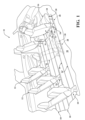
Figure 5 is a partially transparent perspective view of an internal power driving system of the long rail assembly according to one embodiment of the present invention; and -
Figure 6 is an end view of a motor and the long rail assembly according to one embodiment of the present invention. -
Figure 1 illustrates an interior 11 of a vehicle with a plurality oflong rail assemblies 10 configured to reposition a plurality ofseat assemblies 12 along afloor 30 of the vehicle according to embodiments described herein. Eachseat assembly 12 includes aseat cushion 16 and a seat back 14 operatively coupled to theseat cushion 16 for supporting a seat occupant in a generally upright seating position. Eachseat assembly 12 also includes a mountingstructure 18 that supports theseat cushion 16 above thevehicle floor 30. The mountingstructure 18 includes a pair ofrear legs front legs 20. - Each
long rail assembly 10 includes a pair of U-shapedlower channels 26, 26' adapted to be fixedly secured to thevehicle floor 30 and a plurality ofrail drive assemblies 28 that are configured to travel along the U-shapedlower channels 26, 26'. The mountingstructure 18 of theseat assembly 12 is adapted to be fixedly secured to therail drive assembly 28. Theseat assembly 12 may be adjusted among a plurality of fore/aft seating positions along thevehicle floor 30. For example, theseat assembly 12 may be repositioned from afirst seat location 31 to asecond seat location 32 by sliding therail drive assembly 28 that is secured to theseat assembly 12 along the U-shapedlower channels 26, 26'. Although described in terms of the components for the inboard long rail assembly, the present invention includes corresponding structures on the outboard long rail assembly represented by like primed reference numerals. Additional details regarding long rail assemblies for use in automotive vehicles are fully set forth in Applicant's co-pending application no.PCT/US19/62212, entitled "Removable Seat Used with a Long Rail Assembly," filed November 19, 2019 , and co-pending application no.PCT/US19/55835, entitled "Long Rail Assembly for Vehicle Seat Adjustment," filed October 11, 2019 , the disclosures of which are hereby incorporated by reference in their entirety. - Referring to
Figures 2 ,3 ,4 and6 , the U-shapedlower channel 26 includes opposingsidewalls 40, 41 atop wall 42 and abottom wall 44 extending between the opposingsidewalls top wall 42 includes anelongated opening 46 extending in a longitudinal direction. Eachsidewall lower channel 26 is bent into a C-shaped cross-section in profile to formtracks bottom wall 44 of thelower channel 26 is configured to be fixedly attached to thevehicle floor 30. - Referring to
Figures 2-6 , therail drive assembly 28 includes an inverted U-shapedupper channel 58 slidably coupled to thelower channel 26. Theupper channel 58 includes a pair of opposingsidewalls top wall 82 extending therebetween. Therail drive assembly 28 also includesstability rollers 64 projecting from thesidewalls upper channel 58 and atorsion spring 92 to bias thestability rollers 64 against therespective sidewalls lower channel 26. Thestability rollers 64 may project from thesidewalls upper channel 58 and thelower channel 26 within thelong rail assembly 10. - The
rail drive assembly 28 further includes front andrear axles side walls upper channel 58 and opposingwheels 110 that are coupled to the ends of eachaxle wheels 110 are configured to travel along thetracks lower channel 26. - Referring to
Figures 2 and5 therail drive assembly 28 further includes agearbox 66 fixedly secured to and housed within theupper channel 58. Thegearbox 66 includes a vertically orientedworm gear 150 meshingly engaged with aworm wheel 152 within agearbox housing 120. A mountingstructure 122 is fixedly attached to anouter surface 126 of thegearbox housing 120 and mounts thegearbox 66 to thetop wall 82 of theupper channel 58 via bolts, rivets, fasteners, or welds. In an alternative embodiment shown inFigure 3 , theside walls upper channel 58 may extend above the height of thetop wall 42 of thelower channel 26. The tallerupper channel 58 creates enough space for a horizontally orientedworm gear 151. The horizontally orientedworm gear 151 is meshingly engaged with theworm wheel 152 within thegearbox housing 120. The horizontal orientation of theworm gear 151 allows for alternative packaging arrangements as will be discussed further hereinbelow. - The
rail drive assembly 28 also includes adrive shaft 68 and apinion 70. Afirst end 130 of thedrive shaft 68 is fixedly coupled to theworm wheel 152, and an oppositesecond end 132 of thedrive shaft 68 is fixedly coupled to thepinion 70. Thedrive shaft 68 extends out of thegearbox 66 through anopening 134 in thesidewall 80 of theupper channel 58 - Referring to
Figures 2-6 , thelong rail assembly 10 further includes arack 160 fixedly coupled to thetop wall 42 of thelower channel 26. Therack 160 includes a plurality of generally equally spaced apart gearteeth 162 extending along the length of therack 160 in a longitudinal direction. Thegear teeth 162 are oriented towards or facing thebottom wall 44 of thelower channel 26. Thepinion 70 is oriented in a vertical position to meshingly engage with thegear teeth 162 of therack 160. - The
gearbox 66, therack 160 andpinion 70, are packaged inside thelong rail assembly 10 to conceal it from any dirt and debris that may accumulate on thevehicle floor 30. In particular, because thegearbox 66 is mounted within theupper channel 58, theupper channel 58 will prevent any dirt or debris from falling directly intogearbox 66. Similarly, because therack 160 is mounted within thelower channel 26 and thegear teeth 162 of therack 160 are facing downward, any dirt or debris that enters thelower channel 26 will not settle on thegear teeth 162. Moreover, because thegearbox 66, therack 160 and thepinion 70 are elevated above thebottom wall 44 of thelower channel 26, they are not likely to collect any dirt or debris that may accumulate in thelower channel 26. - Referring to
Figures 4-6 , thelong rail assembly 10 further includes anelectric motor 170. Aflexible shaft 180 operatively couples anoutput shaft 172 of themotor 170 to theworm gear 150. Theflexible shaft 180 extends from theoutput shaft 172 through anopening 182 in thetop wall 82 of theupper channel 58 and anopening 184 in thegearbox 66 to the vertically orientedworm gear 150. In the alternative embodiment ofFigure 3 , theflexible shaft 180 extends from theoutput shaft 172 through anopening 185 in either of theside walls upper channel 58 and an opening 187 in thegearbox 66 to the horizontally orientedworm gear 151. This alternative arrangement eliminates some of the bends in theflexible shaft 180 thereby increasing the efficiency and torque of themotor 170. In yet another embodiment, theoutput shaft 172 of themotor 170 can extend directly to the horizontally orientedworm gear 151 through theopening 185 in the upper channel and the opening 187 in thegearbox 66 eliminating the need for theflexible shaft 180 altogether. Themotor 170 may be mounted anywhere on theseat assembly 12. For example, themotor 170 may be mounted to the bottom of theseat cushion 16. Themotor 170 preferably includes twooutput shafts 172 to allow asingle motor 170 to provide power to bothrail drive assemblies 28, 28'. Alternatively, eachrail drive assembly 28, 28' may be powered byseparate motors 170. - In operation, when the
motor 170 is energized to rotate in a first rotational direction, theoutput shaft 172 rotates theflexible shaft 180 causing theworm gear worm gear worm wheel 152 through their meshing engagement. Thedrive shaft 68 transfers the rotation of theworm wheel 152 to thepinion 70. The rotation of thepinion 70 along therack 160 transposes therail drive assembly 28 along thelower channel 26, thereby moving theseat assembly 12 along thelong rail assembly 10 in a first direction. Reversing the rotational direction of themotor 170 results in thepinion 70 rotating in an opposite direction along therack 160, thus moving therail drive assembly 28 and thecorresponding seat assembly 12 along thelower channel 26 in an opposite direction. Finally, pulse width modulation of themotor 170 may provide a more comfortable adjustment speed when theseat assembly 12 is occupied, and a quicker adjustment speed when theseat assembly 12 is unoccupied. - The invention has been described in an illustrative manner, and it is to be understood that the terminology, which has been used, is intended to be in the nature of words of description rather than of limitation. Many modifications and variations of the present invention are possible in light of the above teachings. It is, therefore, to be understood that within the scope of the appended claims, the invention may be practiced other than as specifically described.
Claims (7)
- A long rail assembly (10) for use in a vehicle comprising:a lower channel (26, 26') adapted to extend longitudinally along a floor (30) of the vehicle, wherein the lower channel (26, 26') includes opposing sidewalls (40, 41), a bottom wall (44) and a top wall (42) extending between the opposing sidewalls (40, 41), wherein the top wall (42) has an elongated opening (46) extending in a longitudinal direction;an upper channel (59) slidably coupled to the lower channel (26, 26');a plurality of gears operatively coupled to the upper channel (59);a rack (160) fixedly coupled to the top wall (42) of the lower channel (26, 26'), wherein the rack (160) includes gear teeth (162) extending along the rack (160) in a longitudinal direction and the gear teeth (162) are oriented toward the bottom wall (44) of the lower channel (26, 26');a pinion (70) meshingly engaged with the gear teeth (162);a drive shaft (68) operatively coupling the plurality of gears to the pinion (70); anda motor (170) operatively coupled to the plurality of gears to power drive the upper channel (59) along the lower channel (26, 26').
- The long rail assembly (10) as set forth in claim 8, wherein the plurality of gears are housed within a housing (120) and the housing (120) is fixedly secured to the upper channel (59).
- The long rail assembly (10) as set forth in claim 9, wherein the upper channel (59) includes opposing sidewalls (40, 41) and a top wall (42) extending between the opposing sidewalls (40, 41) and the housing (120) is secured to the top wall (42) of the upper channel (59).
- The long rail assembly (10) as set forth in claim 10, further comprising a flexible drive shaft (180) operatively coupling the motor (170) to the plurality of gears.
- The long rail assembly (10) as set forth in claim 11, wherein the plurality of gears comprises a worm wheel (152) meshingly engaged with a worm gear (150).
- The long rail assembly (10) as set forth in claim 12, wherein the drive shaft (68) operatively couples the worm wheel (152) to the pinion (70).
- The long rail assembly (10) as set forth in claim 13, wherein rotational output from the motor (170) leads to transpositional rotation of the pinion (70) along the rack (160) to slide the upper channel (59) along the lower channel (26, 26').
Applications Claiming Priority (3)
| Application Number | Priority Date | Filing Date | Title |
|---|---|---|---|
| US201962818370P | 2019-03-14 | 2019-03-14 | |
| PCT/US2020/022908 WO2020186259A1 (en) | 2019-03-14 | 2020-03-16 | Long rail assembly with internal power driving system |
| EP20717516.7A EP3902702B1 (en) | 2019-03-14 | 2020-03-16 | Long rail assembly with internal power driving system |
Related Parent Applications (1)
| Application Number | Title | Priority Date | Filing Date |
|---|---|---|---|
| EP20717516.7A Division EP3902702B1 (en) | 2019-03-14 | 2020-03-16 | Long rail assembly with internal power driving system |
Publications (3)
| Publication Number | Publication Date |
|---|---|
| EP4494934A2 true EP4494934A2 (en) | 2025-01-22 |
| EP4494934A3 EP4494934A3 (en) | 2025-03-26 |
| EP4494934B1 EP4494934B1 (en) | 2025-11-05 |
Family
ID=70190236
Family Applications (2)
| Application Number | Title | Priority Date | Filing Date |
|---|---|---|---|
| EP20717516.7A Active EP3902702B1 (en) | 2019-03-14 | 2020-03-16 | Long rail assembly with internal power driving system |
| EP24209245.0A Active EP4494934B1 (en) | 2019-03-14 | 2020-03-16 | Long rail assembly with internal power driving system |
Family Applications Before (1)
| Application Number | Title | Priority Date | Filing Date |
|---|---|---|---|
| EP20717516.7A Active EP3902702B1 (en) | 2019-03-14 | 2020-03-16 | Long rail assembly with internal power driving system |
Country Status (5)
| Country | Link |
|---|---|
| US (1) | US12071044B2 (en) |
| EP (2) | EP3902702B1 (en) |
| CN (1) | CN113710534B (en) |
| CA (1) | CA3133461A1 (en) |
| WO (1) | WO2020186259A1 (en) |
Families Citing this family (12)
| Publication number | Priority date | Publication date | Assignee | Title |
|---|---|---|---|---|
| CA3115975A1 (en) * | 2018-10-11 | 2020-04-16 | Magna Seating Inc. | Long rail assembly for vehicle seat adjustment |
| CA3123867A1 (en) * | 2018-12-17 | 2020-06-25 | Magna Seating Inc. | Loop latch release for power long rail assembly |
| US12071044B2 (en) * | 2019-03-14 | 2024-08-27 | Magna Seating Inc. | Long rail assembly with internal power driving system |
| CA3138998A1 (en) * | 2019-05-03 | 2020-11-12 | Magna Seating Inc. | Long rail assembly with triple rail configuration |
| WO2021155338A1 (en) * | 2020-01-31 | 2021-08-05 | Magna Seating Inc. | Spring loaded gearbox for power long rail assembly |
| CA3166931A1 (en) | 2020-02-07 | 2021-08-12 | Magna Seating Inc. | Transmission system for power long rail assembly |
| US12330537B2 (en) | 2020-09-25 | 2025-06-17 | Magna Seating Inc. | Stability rollers for a long rail assembly |
| DE102021200454B4 (en) | 2021-01-19 | 2024-03-14 | Brose Fahrzeugteile SE & Co. Kommanditgesellschaft, Coburg | Assembly having a guide rail connected to a floor assembly |
| DE102021200455A1 (en) | 2021-01-19 | 2022-07-21 | Brose Fahrzeugteile SE & Co. Kommanditgesellschaft, Coburg | Adjusting device for longitudinal adjustment of a vehicle functional assembly |
| US12022949B2 (en) * | 2022-10-13 | 2024-07-02 | Hidden Lake 822, Llc | Drive motor-linear actuator system for powered lift or powered reclining chairs |
| US20250187499A1 (en) * | 2023-12-07 | 2025-06-12 | Lear Corporation | Track assembly |
| DE102024111380A1 (en) * | 2024-04-23 | 2025-10-23 | Brose Fahrzeugteile SE & Co. Kommanditgesellschaft, Coburg | Adjustment device for longitudinal adjustment of a vehicle functional assembly |
Family Cites Families (49)
| Publication number | Priority date | Publication date | Assignee | Title |
|---|---|---|---|---|
| DE2808884A1 (en) | 1978-03-02 | 1979-09-13 | Keiper Automobiltechnik Gmbh | ADJUSTABLE SEAT TO BE ARRANGED IN A VEHICLE, PREFERABLY A CAR |
| DE3130781A1 (en) * | 1981-08-04 | 1983-02-24 | Keiper Automobiltechnik Gmbh & Co Kg, 5630 Remscheid | Device for adjusting a vehicle seat longitudinally |
| DE3427467A1 (en) * | 1984-07-25 | 1986-02-06 | Brose Fahrzeugteile GmbH & Co KG, 8630 Coburg | SEAT LENGTH ADJUSTMENT |
| JPS6338049A (en) | 1986-07-31 | 1988-02-18 | Oi Seisakusho Co Ltd | Power seat sliding device |
| JPS63147331A (en) | 1986-12-11 | 1988-06-20 | Fujitsu Ltd | Hot-wall epitaxial growth system |
| JPH0428260Y2 (en) * | 1987-03-20 | 1992-07-08 | ||
| JPH0639229B2 (en) * | 1988-08-29 | 1994-05-25 | 株式会社大井製作所 | Power seat slide device |
| JPH0732249Y2 (en) | 1990-05-29 | 1995-07-26 | 池田物産株式会社 | Power seat slide device |
| JPH04252744A (en) * | 1991-01-29 | 1992-09-08 | Oi Seisakusho Co Ltd | Power seat slide device |
| US6499712B1 (en) | 1999-02-03 | 2002-12-31 | Tecla Company, Inc. | Electric seat slide and actuator system |
| JP3678191B2 (en) | 2001-11-12 | 2005-08-03 | アイシン精機株式会社 | Seat slide device |
| WO2003093053A1 (en) | 2002-05-03 | 2003-11-13 | Intier Automotive Inc. | Internal reinforcement bracket for a seat track assembly |
| DE102004013009B4 (en) * | 2004-03-16 | 2008-03-20 | Ims Gear Gmbh | Drive for an adjusting device within a vehicle, in particular a seat adjustment device within a motor vehicle and method for producing such a drive |
| KR100590963B1 (en) | 2004-05-07 | 2006-06-19 | 기아자동차주식회사 | Long slide rails for removable seats for vehicles |
| KR101406672B1 (en) * | 2006-10-23 | 2014-06-11 | 인티어 오토모티브, 인크. | Power seat track drive assembly |
| KR100803305B1 (en) | 2006-10-31 | 2008-02-13 | 현대자동차주식회사 | Seat sliding device of vehicle |
| KR101034307B1 (en) | 2008-09-22 | 2011-05-16 | 현대다이모스(주) | Power long slide rear seat of car |
| JP5662056B2 (en) * | 2010-05-24 | 2015-01-28 | シロキ工業株式会社 | Power slide device |
| JP5621472B2 (en) | 2010-09-28 | 2014-11-12 | アイシン精機株式会社 | Slide device for vehicle and rolling element circulation unit for slide device |
| DE102012212142B4 (en) * | 2012-04-20 | 2014-02-27 | Johnson Controls Gmbh | Device for the electric drive of a longitudinal adjustment device of a vehicle seat |
| DE102012107102A1 (en) * | 2012-08-02 | 2014-02-06 | Dewertokin Gmbh | Electromotive furniture drive |
| CN203391641U (en) * | 2013-06-24 | 2014-01-15 | 富卓汽车内饰(安徽)有限公司 | Hexagonally-adjustable vehicle seat base device |
| US11766956B2 (en) * | 2016-09-08 | 2023-09-26 | Fisher & Company, Incorporated | Open architecture power length adjuster assembly for a vehicle seat and method of manufacturing the same |
| US10953772B2 (en) * | 2016-09-08 | 2021-03-23 | Fisher & Company, Incorporated | Open architecture power length adjuster assembly for a vehicle seat and method of manufacturing the same |
| JP2018075993A (en) | 2016-11-10 | 2018-05-17 | トヨタ紡織株式会社 | Slide device for seat |
| JP2018193007A (en) * | 2017-05-19 | 2018-12-06 | トヨタ紡織株式会社 | Sliding device |
| EP3652018B1 (en) * | 2017-07-14 | 2021-04-14 | Adient Engineering and IP GmbH | Longitudinal adjuster for a vehicle seat, and vehicle seat |
| JP2019098916A (en) * | 2017-12-01 | 2019-06-24 | トヨタ紡織株式会社 | Slide device |
| CN109050353B (en) * | 2018-08-28 | 2020-07-24 | 延锋安道拓座椅机械部件有限公司 | Transmission system of electric long slide rail |
| JP7017490B2 (en) * | 2018-09-27 | 2022-02-08 | トヨタ自動車株式会社 | Vehicle seat structure |
| US11584264B2 (en) * | 2018-10-09 | 2023-02-21 | Magna Seating Inc | Long rail assembly with side opening for vehicle seat adjustment |
| CA3115975A1 (en) * | 2018-10-11 | 2020-04-16 | Magna Seating Inc. | Long rail assembly for vehicle seat adjustment |
| EP3844020B1 (en) * | 2018-10-19 | 2023-08-23 | Magna Seating Inc. | Removable seat used with a long rail assembly |
| EP3907104B1 (en) * | 2019-01-03 | 2025-08-20 | TS Tech Co., Ltd. | Electrically powered slide rail and vehicle seat provided with electrically powered slide rail |
| US11760233B2 (en) * | 2019-02-20 | 2023-09-19 | Fisher & Company, Incorporated | Ultra-compact power length adjuster with anti-back drive capability and pinion-rack output for a vehicle seat |
| US12071044B2 (en) * | 2019-03-14 | 2024-08-27 | Magna Seating Inc. | Long rail assembly with internal power driving system |
| CA3138998A1 (en) * | 2019-05-03 | 2020-11-12 | Magna Seating Inc. | Long rail assembly with triple rail configuration |
| US10894488B2 (en) * | 2019-05-23 | 2021-01-19 | Ford Global Technologies, Llc | Seat adjustment assembly |
| US10960826B2 (en) * | 2019-06-13 | 2021-03-30 | Ford Global Technologies, Llc | Vehicle having a track assembly and a carriage assembly |
| JP7275997B2 (en) * | 2019-08-26 | 2023-05-18 | トヨタ紡織株式会社 | gear box |
| CN110626224B (en) | 2019-10-31 | 2025-08-05 | 湖北航嘉麦格纳座椅系统有限公司 | Seat assembly and electric slide rail |
| EP4010221B1 (en) * | 2019-11-06 | 2023-05-31 | Magna Seating Inc. | Gearbox quick connection for long rail assembly |
| CA3098743A1 (en) * | 2019-11-11 | 2021-05-11 | Magna Seating Inc. | Long rail assembly with retention latch |
| WO2021125343A1 (en) * | 2019-12-20 | 2021-06-24 | テイ・エス テック株式会社 | Slide lock structure of slide rail device |
| WO2021155338A1 (en) * | 2020-01-31 | 2021-08-05 | Magna Seating Inc. | Spring loaded gearbox for power long rail assembly |
| CA3166931A1 (en) * | 2020-02-07 | 2021-08-12 | Magna Seating Inc. | Transmission system for power long rail assembly |
| US11485255B2 (en) * | 2020-05-01 | 2022-11-01 | Fisher & Company, Incorporated | Gearbox for vehicle seat adjustment mechanism |
| CN113665442A (en) * | 2020-05-14 | 2021-11-19 | 李尔公司 | Track assembly |
| CN114537229B (en) * | 2022-03-18 | 2026-04-21 | 湖北航嘉麦格纳座椅系统有限公司 | A slide rail transmission device and a vehicle |
-
2020
- 2020-03-16 US US17/439,211 patent/US12071044B2/en active Active
- 2020-03-16 EP EP20717516.7A patent/EP3902702B1/en active Active
- 2020-03-16 EP EP24209245.0A patent/EP4494934B1/en active Active
- 2020-03-16 CN CN202080020500.5A patent/CN113710534B/en active Active
- 2020-03-16 CA CA3133461A patent/CA3133461A1/en active Pending
- 2020-03-16 WO PCT/US2020/022908 patent/WO2020186259A1/en not_active Ceased
Also Published As
| Publication number | Publication date |
|---|---|
| EP4494934B1 (en) | 2025-11-05 |
| US20220161691A1 (en) | 2022-05-26 |
| US12071044B2 (en) | 2024-08-27 |
| CN113710534A (en) | 2021-11-26 |
| WO2020186259A1 (en) | 2020-09-17 |
| CN113710534B (en) | 2023-08-04 |
| CA3133461A1 (en) | 2020-09-17 |
| EP3902702A1 (en) | 2021-11-03 |
| EP3902702B1 (en) | 2024-10-30 |
| EP4494934A3 (en) | 2025-03-26 |
Similar Documents
| Publication | Publication Date | Title |
|---|---|---|
| EP3902702B1 (en) | Long rail assembly with internal power driving system | |
| EP3924216B1 (en) | Long rail assembly with triple rail configuration | |
| JP7355823B2 (en) | Front-rear adjuster for vehicle seat and vehicle seat | |
| US7503537B2 (en) | Power seat slide apparatus | |
| EP4054889B1 (en) | Transmission system for power long rail assembly | |
| US6431298B1 (en) | Drive unit assembly for an electrically driven vehicle | |
| KR20150006858A (en) | Device for electrically driving a longitudinal adjustment mechanism for a vehicle seat | |
| KR101987006B1 (en) | Electric-powered sliding console for vehicle | |
| EP4269170A1 (en) | Slide rail transmission apparatus and vehicle | |
| EP4011694A1 (en) | Seat frame | |
| US5018696A (en) | Power seat adjuster with floating drive mechanism | |
| JP5733095B2 (en) | Power seat slide device | |
| WO2018029919A1 (en) | Vehicle seat | |
| JP2001105939A (en) | Vehicle seat position adjustment device | |
| KR102530211B1 (en) | Sliding apparatus of seat for vehicle | |
| EP4541651A1 (en) | Automobile seat and automobile having same | |
| KR20220013617A (en) | Efficient dual-motor electric seat track | |
| WO2011150489A1 (en) | Power drive assembly for a seat track assembly featuring compressible ribs | |
| CN222629177U (en) | Handle device of vehicle and vehicle | |
| CN113147527B (en) | Electric long sliding rail of automobile seat and transmission method thereof | |
| JP2013226921A (en) | Slide device | |
| JPH0611227Y2 (en) | Power unit for seat | |
| JPH0635030U (en) | Power seat device with seat lifter | |
| JP2003220861A (en) | Power seat truck |
Legal Events
| Date | Code | Title | Description |
|---|---|---|---|
| PUAI | Public reference made under article 153(3) epc to a published international application that has entered the european phase |
Free format text: ORIGINAL CODE: 0009012 |
|
| STAA | Information on the status of an ep patent application or granted ep patent |
Free format text: STATUS: THE APPLICATION HAS BEEN PUBLISHED |
|
| AC | Divisional application: reference to earlier application |
Ref document number: 3902702 Country of ref document: EP Kind code of ref document: P |
|
| AK | Designated contracting states |
Kind code of ref document: A2 Designated state(s): AL AT BE BG CH CY CZ DE DK EE ES FI FR GB GR HR HU IE IS IT LI LT LU LV MC MK MT NL NO PL PT RO RS SE SI SK SM TR |
|
| REG | Reference to a national code |
Ref country code: DE Ref legal event code: R079 Free format text: PREVIOUS MAIN CLASS: B60N0002070000 Ipc: B60N0002060000 Ref country code: DE Ref legal event code: R079 Ref document number: 602020061990 Country of ref document: DE Free format text: PREVIOUS MAIN CLASS: B60N0002070000 Ipc: B60N0002060000 |
|
| PUAL | Search report despatched |
Free format text: ORIGINAL CODE: 0009013 |
|
| AK | Designated contracting states |
Kind code of ref document: A3 Designated state(s): AL AT BE BG CH CY CZ DE DK EE ES FI FR GB GR HR HU IE IS IT LI LT LU LV MC MK MT NL NO PL PT RO RS SE SI SK SM TR |
|
| RIC1 | Information provided on ipc code assigned before grant |
Ipc: B60N 2/07 20060101ALI20250218BHEP Ipc: B60N 2/06 20060101AFI20250218BHEP |
|
| STAA | Information on the status of an ep patent application or granted ep patent |
Free format text: STATUS: REQUEST FOR EXAMINATION WAS MADE |
|
| 17P | Request for examination filed |
Effective date: 20250412 |
|
| GRAP | Despatch of communication of intention to grant a patent |
Free format text: ORIGINAL CODE: EPIDOSNIGR1 |
|
| STAA | Information on the status of an ep patent application or granted ep patent |
Free format text: STATUS: GRANT OF PATENT IS INTENDED |
|
| GRAJ | Information related to disapproval of communication of intention to grant by the applicant or resumption of examination proceedings by the epo deleted |
Free format text: ORIGINAL CODE: EPIDOSDIGR1 |
|
| STAA | Information on the status of an ep patent application or granted ep patent |
Free format text: STATUS: REQUEST FOR EXAMINATION WAS MADE |
|
| INTG | Intention to grant announced |
Effective date: 20250701 |
|
| INTC | Intention to grant announced (deleted) | ||
| GRAP | Despatch of communication of intention to grant a patent |
Free format text: ORIGINAL CODE: EPIDOSNIGR1 |
|
| STAA | Information on the status of an ep patent application or granted ep patent |
Free format text: STATUS: GRANT OF PATENT IS INTENDED |
|
| GRAS | Grant fee paid |
Free format text: ORIGINAL CODE: EPIDOSNIGR3 |
|
| GRAA | (expected) grant |
Free format text: ORIGINAL CODE: 0009210 |
|
| STAA | Information on the status of an ep patent application or granted ep patent |
Free format text: STATUS: THE PATENT HAS BEEN GRANTED |
|
| INTG | Intention to grant announced |
Effective date: 20250904 |
|
| AC | Divisional application: reference to earlier application |
Ref document number: 3902702 Country of ref document: EP Kind code of ref document: P |
|
| AK | Designated contracting states |
Kind code of ref document: B1 Designated state(s): AL AT BE BG CH CY CZ DE DK EE ES FI FR GB GR HR HU IE IS IT LI LT LU LV MC MK MT NL NO PL PT RO RS SE SI SK SM TR |
|
| REG | Reference to a national code |
Ref country code: CH Ref legal event code: F10 Free format text: ST27 STATUS EVENT CODE: U-0-0-F10-F00 (AS PROVIDED BY THE NATIONAL OFFICE) Effective date: 20251105 Ref country code: GB Ref legal event code: FG4D |
|
| P01 | Opt-out of the competence of the unified patent court (upc) registered |
Free format text: CASE NUMBER: UPC_APP_9292_4494934/2025 Effective date: 20251008 |
|
| REG | Reference to a national code |
Ref country code: DE Ref legal event code: R096 Ref document number: 602020061990 Country of ref document: DE |
|
| REG | Reference to a national code |
Ref country code: IE Ref legal event code: FG4D |
|
| PGFP | Annual fee paid to national office [announced via postgrant information from national office to epo] |
Ref country code: FR Payment date: 20251231 Year of fee payment: 7 |
|
| REG | Reference to a national code |
Ref country code: NL Ref legal event code: MP Effective date: 20251105 |
|
| PG25 | Lapsed in a contracting state [announced via postgrant information from national office to epo] |
Ref country code: ES Free format text: LAPSE BECAUSE OF FAILURE TO SUBMIT A TRANSLATION OF THE DESCRIPTION OR TO PAY THE FEE WITHIN THE PRESCRIBED TIME-LIMIT Effective date: 20251105 |
|
| REG | Reference to a national code |
Ref country code: LT Ref legal event code: MG9D |
|
| PG25 | Lapsed in a contracting state [announced via postgrant information from national office to epo] |
Ref country code: NO Free format text: LAPSE BECAUSE OF FAILURE TO SUBMIT A TRANSLATION OF THE DESCRIPTION OR TO PAY THE FEE WITHIN THE PRESCRIBED TIME-LIMIT Effective date: 20260205 |
|
| PGFP | Annual fee paid to national office [announced via postgrant information from national office to epo] |
Ref country code: DE Payment date: 20260102 Year of fee payment: 7 |
|
| PG25 | Lapsed in a contracting state [announced via postgrant information from national office to epo] |
Ref country code: AT Free format text: LAPSE BECAUSE OF FAILURE TO SUBMIT A TRANSLATION OF THE DESCRIPTION OR TO PAY THE FEE WITHIN THE PRESCRIBED TIME-LIMIT Effective date: 20251105 Ref country code: FI Free format text: LAPSE BECAUSE OF FAILURE TO SUBMIT A TRANSLATION OF THE DESCRIPTION OR TO PAY THE FEE WITHIN THE PRESCRIBED TIME-LIMIT Effective date: 20251105 Ref country code: HR Free format text: LAPSE BECAUSE OF FAILURE TO SUBMIT A TRANSLATION OF THE DESCRIPTION OR TO PAY THE FEE WITHIN THE PRESCRIBED TIME-LIMIT Effective date: 20251105 |
|
| REG | Reference to a national code |
Ref country code: AT Ref legal event code: MK05 Ref document number: 1854013 Country of ref document: AT Kind code of ref document: T Effective date: 20251105 |
|
| PG25 | Lapsed in a contracting state [announced via postgrant information from national office to epo] |
Ref country code: NL Free format text: LAPSE BECAUSE OF FAILURE TO SUBMIT A TRANSLATION OF THE DESCRIPTION OR TO PAY THE FEE WITHIN THE PRESCRIBED TIME-LIMIT Effective date: 20251105 |
|
| PG25 | Lapsed in a contracting state [announced via postgrant information from national office to epo] |
Ref country code: RS Free format text: LAPSE BECAUSE OF FAILURE TO SUBMIT A TRANSLATION OF THE DESCRIPTION OR TO PAY THE FEE WITHIN THE PRESCRIBED TIME-LIMIT Effective date: 20260205 |
|
| PG25 | Lapsed in a contracting state [announced via postgrant information from national office to epo] |
Ref country code: IS Free format text: LAPSE BECAUSE OF FAILURE TO SUBMIT A TRANSLATION OF THE DESCRIPTION OR TO PAY THE FEE WITHIN THE PRESCRIBED TIME-LIMIT Effective date: 20260305 |
|
| PG25 | Lapsed in a contracting state [announced via postgrant information from national office to epo] |
Ref country code: PT Free format text: LAPSE BECAUSE OF FAILURE TO SUBMIT A TRANSLATION OF THE DESCRIPTION OR TO PAY THE FEE WITHIN THE PRESCRIBED TIME-LIMIT Effective date: 20260305 |
|
| PG25 | Lapsed in a contracting state [announced via postgrant information from national office to epo] |
Ref country code: PL Free format text: LAPSE BECAUSE OF FAILURE TO SUBMIT A TRANSLATION OF THE DESCRIPTION OR TO PAY THE FEE WITHIN THE PRESCRIBED TIME-LIMIT Effective date: 20251105 |
|
| PG25 | Lapsed in a contracting state [announced via postgrant information from national office to epo] |
Ref country code: LV Free format text: LAPSE BECAUSE OF FAILURE TO SUBMIT A TRANSLATION OF THE DESCRIPTION OR TO PAY THE FEE WITHIN THE PRESCRIBED TIME-LIMIT Effective date: 20251105 |