EP4494907A1 - Vehicle-mounted battery pack locking system, method and device, and storage medium - Google Patents
Vehicle-mounted battery pack locking system, method and device, and storage medium Download PDFInfo
- Publication number
- EP4494907A1 EP4494907A1 EP22931806.8A EP22931806A EP4494907A1 EP 4494907 A1 EP4494907 A1 EP 4494907A1 EP 22931806 A EP22931806 A EP 22931806A EP 4494907 A1 EP4494907 A1 EP 4494907A1
- Authority
- EP
- European Patent Office
- Prior art keywords
- battery pack
- vehicle
- locking
- battery
- wedge
- Prior art date
- Legal status (The legal status is an assumption and is not a legal conclusion. Google has not performed a legal analysis and makes no representation as to the accuracy of the status listed.)
- Pending
Links
Images




Classifications
-
- H—ELECTRICITY
- H01—ELECTRIC ELEMENTS
- H01M—PROCESSES OR MEANS, e.g. BATTERIES, FOR THE DIRECT CONVERSION OF CHEMICAL ENERGY INTO ELECTRICAL ENERGY
- H01M50/00—Constructional details or processes of manufacture of the non-active parts of electrochemical cells other than fuel cells, e.g. hybrid cells
- H01M50/20—Mountings; Secondary casings or frames; Racks, modules or packs; Suspension devices; Shock absorbers; Transport or carrying devices; Holders
- H01M50/249—Mountings; Secondary casings or frames; Racks, modules or packs; Suspension devices; Shock absorbers; Transport or carrying devices; Holders specially adapted for aircraft or vehicles, e.g. cars or trains
-
- B—PERFORMING OPERATIONS; TRANSPORTING
- B60—VEHICLES IN GENERAL
- B60K—ARRANGEMENT OR MOUNTING OF PROPULSION UNITS OR OF TRANSMISSIONS IN VEHICLES; ARRANGEMENT OR MOUNTING OF PLURAL DIVERSE PRIME-MOVERS IN VEHICLES; AUXILIARY DRIVES FOR VEHICLES; INSTRUMENTATION OR DASHBOARDS FOR VEHICLES; ARRANGEMENTS IN CONNECTION WITH COOLING, AIR INTAKE, GAS EXHAUST OR FUEL SUPPLY OF PROPULSION UNITS IN VEHICLES
- B60K1/00—Arrangement or mounting of electrical propulsion units
- B60K1/04—Arrangement or mounting of electrical propulsion units of the electric storage means for propulsion
-
- B—PERFORMING OPERATIONS; TRANSPORTING
- B60—VEHICLES IN GENERAL
- B60L—PROPULSION OF ELECTRICALLY-PROPELLED VEHICLES; SUPPLYING ELECTRIC POWER FOR AUXILIARY EQUIPMENT OF ELECTRICALLY-PROPELLED VEHICLES; ELECTRODYNAMIC BRAKE SYSTEMS FOR VEHICLES IN GENERAL; MAGNETIC SUSPENSION OR LEVITATION FOR VEHICLES; MONITORING OPERATING VARIABLES OF ELECTRICALLY-PROPELLED VEHICLES; ELECTRIC SAFETY DEVICES FOR ELECTRICALLY-PROPELLED VEHICLES
- B60L50/00—Electric propulsion with power supplied within the vehicle
- B60L50/50—Electric propulsion with power supplied within the vehicle using propulsion power supplied by batteries or fuel cells
- B60L50/60—Electric propulsion with power supplied within the vehicle using propulsion power supplied by batteries or fuel cells using power supplied by batteries
- B60L50/64—Constructional details of batteries specially adapted for electric vehicles
-
- B—PERFORMING OPERATIONS; TRANSPORTING
- B60—VEHICLES IN GENERAL
- B60L—PROPULSION OF ELECTRICALLY-PROPELLED VEHICLES; SUPPLYING ELECTRIC POWER FOR AUXILIARY EQUIPMENT OF ELECTRICALLY-PROPELLED VEHICLES; ELECTRODYNAMIC BRAKE SYSTEMS FOR VEHICLES IN GENERAL; MAGNETIC SUSPENSION OR LEVITATION FOR VEHICLES; MONITORING OPERATING VARIABLES OF ELECTRICALLY-PROPELLED VEHICLES; ELECTRIC SAFETY DEVICES FOR ELECTRICALLY-PROPELLED VEHICLES
- B60L50/00—Electric propulsion with power supplied within the vehicle
- B60L50/50—Electric propulsion with power supplied within the vehicle using propulsion power supplied by batteries or fuel cells
- B60L50/60—Electric propulsion with power supplied within the vehicle using propulsion power supplied by batteries or fuel cells using power supplied by batteries
- B60L50/66—Arrangements of batteries
-
- B—PERFORMING OPERATIONS; TRANSPORTING
- B60—VEHICLES IN GENERAL
- B60L—PROPULSION OF ELECTRICALLY-PROPELLED VEHICLES; SUPPLYING ELECTRIC POWER FOR AUXILIARY EQUIPMENT OF ELECTRICALLY-PROPELLED VEHICLES; ELECTRODYNAMIC BRAKE SYSTEMS FOR VEHICLES IN GENERAL; MAGNETIC SUSPENSION OR LEVITATION FOR VEHICLES; MONITORING OPERATING VARIABLES OF ELECTRICALLY-PROPELLED VEHICLES; ELECTRIC SAFETY DEVICES FOR ELECTRICALLY-PROPELLED VEHICLES
- B60L53/00—Methods of charging batteries, specially adapted for electric vehicles; Charging stations or on-board charging equipment therefor; Exchange of energy storage elements in electric vehicles
- B60L53/80—Exchanging energy storage elements, e.g. removable batteries
-
- H—ELECTRICITY
- H01—ELECTRIC ELEMENTS
- H01M—PROCESSES OR MEANS, e.g. BATTERIES, FOR THE DIRECT CONVERSION OF CHEMICAL ENERGY INTO ELECTRICAL ENERGY
- H01M50/00—Constructional details or processes of manufacture of the non-active parts of electrochemical cells other than fuel cells, e.g. hybrid cells
- H01M50/20—Mountings; Secondary casings or frames; Racks, modules or packs; Suspension devices; Shock absorbers; Transport or carrying devices; Holders
- H01M50/244—Secondary casings; Racks; Suspension devices; Carrying devices; Holders characterised by their mounting method
-
- H—ELECTRICITY
- H01—ELECTRIC ELEMENTS
- H01M—PROCESSES OR MEANS, e.g. BATTERIES, FOR THE DIRECT CONVERSION OF CHEMICAL ENERGY INTO ELECTRICAL ENERGY
- H01M50/00—Constructional details or processes of manufacture of the non-active parts of electrochemical cells other than fuel cells, e.g. hybrid cells
- H01M50/20—Mountings; Secondary casings or frames; Racks, modules or packs; Suspension devices; Shock absorbers; Transport or carrying devices; Holders
- H01M50/262—Mountings; Secondary casings or frames; Racks, modules or packs; Suspension devices; Shock absorbers; Transport or carrying devices; Holders with fastening means, e.g. locks
- H01M50/264—Mountings; Secondary casings or frames; Racks, modules or packs; Suspension devices; Shock absorbers; Transport or carrying devices; Holders with fastening means, e.g. locks for cells or batteries, e.g. straps, tie rods or peripheral frames
-
- B—PERFORMING OPERATIONS; TRANSPORTING
- B60—VEHICLES IN GENERAL
- B60K—ARRANGEMENT OR MOUNTING OF PROPULSION UNITS OR OF TRANSMISSIONS IN VEHICLES; ARRANGEMENT OR MOUNTING OF PLURAL DIVERSE PRIME-MOVERS IN VEHICLES; AUXILIARY DRIVES FOR VEHICLES; INSTRUMENTATION OR DASHBOARDS FOR VEHICLES; ARRANGEMENTS IN CONNECTION WITH COOLING, AIR INTAKE, GAS EXHAUST OR FUEL SUPPLY OF PROPULSION UNITS IN VEHICLES
- B60K1/00—Arrangement or mounting of electrical propulsion units
- B60K1/04—Arrangement or mounting of electrical propulsion units of the electric storage means for propulsion
- B60K2001/0405—Arrangement or mounting of electrical propulsion units of the electric storage means for propulsion characterised by their position
- B60K2001/0438—Arrangement under the floor
-
- B—PERFORMING OPERATIONS; TRANSPORTING
- B60—VEHICLES IN GENERAL
- B60K—ARRANGEMENT OR MOUNTING OF PROPULSION UNITS OR OF TRANSMISSIONS IN VEHICLES; ARRANGEMENT OR MOUNTING OF PLURAL DIVERSE PRIME-MOVERS IN VEHICLES; AUXILIARY DRIVES FOR VEHICLES; INSTRUMENTATION OR DASHBOARDS FOR VEHICLES; ARRANGEMENTS IN CONNECTION WITH COOLING, AIR INTAKE, GAS EXHAUST OR FUEL SUPPLY OF PROPULSION UNITS IN VEHICLES
- B60K1/00—Arrangement or mounting of electrical propulsion units
- B60K1/04—Arrangement or mounting of electrical propulsion units of the electric storage means for propulsion
- B60K2001/0455—Removal or replacement of the energy storages
-
- B—PERFORMING OPERATIONS; TRANSPORTING
- B60—VEHICLES IN GENERAL
- B60K—ARRANGEMENT OR MOUNTING OF PROPULSION UNITS OR OF TRANSMISSIONS IN VEHICLES; ARRANGEMENT OR MOUNTING OF PLURAL DIVERSE PRIME-MOVERS IN VEHICLES; AUXILIARY DRIVES FOR VEHICLES; INSTRUMENTATION OR DASHBOARDS FOR VEHICLES; ARRANGEMENTS IN CONNECTION WITH COOLING, AIR INTAKE, GAS EXHAUST OR FUEL SUPPLY OF PROPULSION UNITS IN VEHICLES
- B60K1/00—Arrangement or mounting of electrical propulsion units
- B60K1/04—Arrangement or mounting of electrical propulsion units of the electric storage means for propulsion
- B60K2001/0455—Removal or replacement of the energy storages
- B60K2001/0461—Removal or replacement of the energy storages from the side
-
- B—PERFORMING OPERATIONS; TRANSPORTING
- B60—VEHICLES IN GENERAL
- B60K—ARRANGEMENT OR MOUNTING OF PROPULSION UNITS OR OF TRANSMISSIONS IN VEHICLES; ARRANGEMENT OR MOUNTING OF PLURAL DIVERSE PRIME-MOVERS IN VEHICLES; AUXILIARY DRIVES FOR VEHICLES; INSTRUMENTATION OR DASHBOARDS FOR VEHICLES; ARRANGEMENTS IN CONNECTION WITH COOLING, AIR INTAKE, GAS EXHAUST OR FUEL SUPPLY OF PROPULSION UNITS IN VEHICLES
- B60K1/00—Arrangement or mounting of electrical propulsion units
- B60K1/04—Arrangement or mounting of electrical propulsion units of the electric storage means for propulsion
- B60K2001/0455—Removal or replacement of the energy storages
- B60K2001/0472—Removal or replacement of the energy storages from below
-
- B—PERFORMING OPERATIONS; TRANSPORTING
- B60—VEHICLES IN GENERAL
- B60K—ARRANGEMENT OR MOUNTING OF PROPULSION UNITS OR OF TRANSMISSIONS IN VEHICLES; ARRANGEMENT OR MOUNTING OF PLURAL DIVERSE PRIME-MOVERS IN VEHICLES; AUXILIARY DRIVES FOR VEHICLES; INSTRUMENTATION OR DASHBOARDS FOR VEHICLES; ARRANGEMENTS IN CONNECTION WITH COOLING, AIR INTAKE, GAS EXHAUST OR FUEL SUPPLY OF PROPULSION UNITS IN VEHICLES
- B60K1/00—Arrangement or mounting of electrical propulsion units
- B60K1/04—Arrangement or mounting of electrical propulsion units of the electric storage means for propulsion
- B60K2001/0455—Removal or replacement of the energy storages
- B60K2001/0494—Removal or replacement of the energy storages with arrangements for sliding
-
- H—ELECTRICITY
- H01—ELECTRIC ELEMENTS
- H01M—PROCESSES OR MEANS, e.g. BATTERIES, FOR THE DIRECT CONVERSION OF CHEMICAL ENERGY INTO ELECTRICAL ENERGY
- H01M2220/00—Batteries for particular applications
- H01M2220/20—Batteries in motive systems, e.g. vehicle, ship, plane
-
- Y—GENERAL TAGGING OF NEW TECHNOLOGICAL DEVELOPMENTS; GENERAL TAGGING OF CROSS-SECTIONAL TECHNOLOGIES SPANNING OVER SEVERAL SECTIONS OF THE IPC; TECHNICAL SUBJECTS COVERED BY FORMER USPC CROSS-REFERENCE ART COLLECTIONS [XRACs] AND DIGESTS
- Y02—TECHNOLOGIES OR APPLICATIONS FOR MITIGATION OR ADAPTATION AGAINST CLIMATE CHANGE
- Y02T—CLIMATE CHANGE MITIGATION TECHNOLOGIES RELATED TO TRANSPORTATION
- Y02T10/00—Road transport of goods or passengers
- Y02T10/60—Other road transportation technologies with climate change mitigation effect
- Y02T10/70—Energy storage systems for electromobility, e.g. batteries
-
- Y—GENERAL TAGGING OF NEW TECHNOLOGICAL DEVELOPMENTS; GENERAL TAGGING OF CROSS-SECTIONAL TECHNOLOGIES SPANNING OVER SEVERAL SECTIONS OF THE IPC; TECHNICAL SUBJECTS COVERED BY FORMER USPC CROSS-REFERENCE ART COLLECTIONS [XRACs] AND DIGESTS
- Y02—TECHNOLOGIES OR APPLICATIONS FOR MITIGATION OR ADAPTATION AGAINST CLIMATE CHANGE
- Y02T—CLIMATE CHANGE MITIGATION TECHNOLOGIES RELATED TO TRANSPORTATION
- Y02T10/00—Road transport of goods or passengers
- Y02T10/60—Other road transportation technologies with climate change mitigation effect
- Y02T10/7072—Electromobility specific charging systems or methods for batteries, ultracapacitors, supercapacitors or double-layer capacitors
Definitions
- the present disclosure relates to the field of battery swap for large new energy vehicles, and more particularly to a vehicle-mounted battery pack locking system, a method, a device and a storage medium.
- a group of connecting rods arranged parallel to the first direction are provided at a bottom portion of the battery pack, and the second wedge blocks are respectively provided at two ends of each connecting rod, the slope of the second wedge block faces upward, and the slope of the first wedge block faces downward, the slope of the first wedge block is in surface contact with the slope of the second wedge block to fit together for self-locking, a locking force of the limit slider along the first direction is converted into a downward pressure that presses the battery pack against a bottom plate of the battery position, so that the battery pack is limited to the battery position between the second wedge blocks at the two ends of the battery position, and the first direction is a width direction of the battery swap vehicle.
- the locking assembly further includes linear limit assemblies respectively arranged on the locking assemblies and a vehicle body of the battery swap vehicle.
- the linear limit assembly includes a dovetail groove arranged at a bottom portion of the limit slider and a dovetail tenon fixed at the battery position in the vehicle body, and the dovetail groove is slidable in the dovetail tenon along the first direction.
- the locking assembly further includes a cylinder configured to drive the limit slider to move along the first direction through a cylinder rod.
- the locking assembly further includes a spring configured to push the limit slider toward the second wedge block of the battery pack, wherein the spring and the cylinder are respectively arranged on two sides of the limit slider along the first direction.
- the battery position when the cylinder overcomes a thrust of the spring and pushes the limit slider away from the second wedge block, the battery position is in an unlocked state for inserting or removing the battery pack.
- the purpose of the present disclosure is to provide a vehicle-mounted battery pack locking system, a method, a device and a storage medium, to spatially lock the battery pack and provide double locking protection in the insertion direction of the battery pack, which can not only be unlocked quickly, but also provide a strong locking effect.
- the certain device When a certain device is “on” another device, the certain device may be directly on the other device, or other devices may be interposed therebetween. By comparison, when a device is referred to as being “directly on” another device, there are no intervening devices.
- first, second, etc. are used herein to refer to various elements in some examples, these elements should not be limited by these terms. These terms are only used to distinguish one element from another. For example, a first interface and a second interface are indicated.
- singular forms “a”, “an” and “the” are intended to include the plural forms as well, unless the context indicates otherwise.
- the terms “comprises” and “includes” indicate the existence of features, steps, operations, elements, components, items, types, and/or groups, but do not exclude the existence, occurrence, or addition of one or more other features, steps, operations, elements, components, items, types, and/or groups.
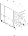
- FIG. 1 is a schematic view of a vehicle-mounted battery pack locking system of the present disclosure.
- FIG. 2 is a schematic view of the vehicle-mounted battery pack locking system and a battery pack in an unlocked state of the present disclosure.
- FIG. 3 is an enlarged view of A area in FIG. 2 .
- FIG. 4 is a schematic view of the vehicle-mounted battery pack locking system and a battery pack in a locked state of the present disclosure.
- FIG. 5 is an enlarged view of B area in FIG. 4 .
- the vehicle-mounted battery pack locking system of the present disclosure is particularly suitable for large new energy vehicles equipped with large battery packs.
- the vehicle-mounted battery pack locking system includes: a battery swap passage and at least two locking components 3.
- the battery swap passage allows the battery pack 4 to enter and exit the battery position 2 of the battery swap vehicle 1 along a first direction.
- a group of connecting rods 41 parallel to the first direction are arranged at the bottom of the battery pack 4.
- At least one second wedge block 42 is provided at each of two ends of each connecting rod 41.
- the wedge-shaped slope of the second wedge block 42 extends along the first direction.
- Four locking assemblies 3 are respectively arranged at two ends of the battery position 2 along the first direction.
- Each locking assembly 3 at least includes a first wedge block 31, a limit slider 32 and a linear limit assembly respectively arranged on the locking assembly 3 and a vehicle body of the battery swap vehicle 1.
- the limit slider 32 is limited to linearly moveable only along the first direction.
- the first wedge block 31 is connected to one side of the limit slider 32.
- the limit sliders 32 at the two ends are respectively pushed toward the battery pack 4 by a bias force.
- the wedge-shaped slope 38 of the first wedge block 31 is respectively fitted and self-locked with the corresponding second wedge block 42, to bidirectionally limit the position of the battery pack along the first direction.
- a second wedge block 42 is respectively provided at each of the two ends of each connecting rod 41, the slope surface of the second wedge block 42 faces upward, the slope surface of the first wedge block 31 faces downward, and the first direction is a width direction of the battery-swap vehicle 1.
- the first direction (Y direction, a width direction of the vehicle body) is perpendicular to the length direction (X direction, a length direction of the vehicle body) of the battery-swap vehicle 1.
- a battery swap robot 5 takes out the battery pack 4 from a container battery compartment 6, and inserts the battery pack 4 into the battery position 2 of the battery swap vehicle 1 along the width direction of the vehicle body, and firmly locks the battery pack 4 in the battery position 2 with the locking assembly 3 to prevent the battery pack from shaking in the vertical direction, the length direction and the width direction of the vehicle when the vehicle is driving.
- the program code for performing the operations of the present disclosure may be written in any combination of one or more programming languages, which may include a target-oriented programming language, such as the Java and C++, or may include conventional formula programming language, such as "C" language or similar programming language.
- the program code may be entirely executed on the user computing device, partly executed on the user device, executed as an independent software package, partly executed on the user computing device and partly executed on a remote computing device, or entirely executed on the remote computing device or server.
- the remote computing device may be connected to the user computing device through any kind of network, including a local area network (LAN) or a wide area network (WAN), or may be connected to an external computing device (e.g., through connection via the Internet using Internet service provider).
- LAN local area network
- WAN wide area network
Landscapes
- Engineering & Computer Science (AREA)
- Chemical & Material Sciences (AREA)
- Chemical Kinetics & Catalysis (AREA)
- Electrochemistry (AREA)
- General Chemical & Material Sciences (AREA)
- Mechanical Engineering (AREA)
- Transportation (AREA)
- Power Engineering (AREA)
- Sustainable Energy (AREA)
- Sustainable Development (AREA)
- Life Sciences & Earth Sciences (AREA)
- Aviation & Aerospace Engineering (AREA)
- Combustion & Propulsion (AREA)
- Battery Mounting, Suspending (AREA)
- Arrangement Or Mounting Of Propulsion Units For Vehicles (AREA)
Abstract
Description
- The present disclosure relates to the field of battery swap for large new energy vehicles, and more particularly to a vehicle-mounted battery pack locking system, a method, a device and a storage medium.
- In a battery swap station system, after the battery pack is swapped, the battery pack needs to be locked to be prevented from moving, but the battery pack also needs to be able to be unlocked and locked quickly. Some existing locking devices have complex structures and complicated operations, which cannot be unlocked quickly. Some existing locking devices require a large space, don't have enough strength, and are easy to loosen. Furthermore, most locking devices lack double protection.
- Especially in the battery swap scenario currently used in large trucks and other heavy new energy vehicles, the battery pack is very heavy. If the battery pack cannot be stably fixed in the car, once the battery pack needs to be swapped, the center of gravity of the vehicle will be affected and the stability of the driving state (especially when turning or accelerating) will be destroyed. In severe cases, driving safety will be affected.
- Concerning the problems in the prior art, the purpose of the present disclosure is to provide a vehicle-mounted battery pack locking system, a method, a device and a storage medium, to overcome the difficulties of the prior art, spatially lock the battery pack, and provide double locking protection in the insertion direction of the battery pack, which can not only be unlocked quickly, but also provide a strong locking effect.
- An embodiment of the present disclosure provides a vehicle-mounted battery pack locking system including:
- a battery swap passage for a battery pack to enter and exit a battery position of a battery swap vehicle along a first direction, wherein at least one second wedge block is provided at each of two ends of the battery pack, and a wedge-shaped slope of the second wedge block is configured to extend along the first direction; and
- at least two locking assemblies respectively arranged at two ends of the battery position along the first direction, wherein each locking assembly at least includes one limit slider and a first wedge block, the limit slider is limited to be linearly movable only along the first direction, the first wedge block is connected to one side of the limit slider, the limit sliders at the two ends of the battery position are pushed toward the battery pack by a bias force, and a wedge-shaped slope of each first wedge block is respectively fitted and self-locked with the corresponding second wedge block, to bidirectionally limit the position of the battery pack along the first direction.
- In some embodiments, a group of connecting rods arranged parallel to the first direction are provided at a bottom portion of the battery pack, and the second wedge blocks are respectively provided at two ends of each connecting rod, the slope of the second wedge block faces upward, and the slope of the first wedge block faces downward, the slope of the first wedge block is in surface contact with the slope of the second wedge block to fit together for self-locking, a locking force of the limit slider along the first direction is converted into a downward pressure that presses the battery pack against a bottom plate of the battery position, so that the battery pack is limited to the battery position between the second wedge blocks at the two ends of the battery position, and the first direction is a width direction of the battery swap vehicle.
- In some embodiments, the locking assembly further includes linear limit assemblies respectively arranged on the locking assemblies and a vehicle body of the battery swap vehicle.
- In some embodiments, the linear limit assembly includes a dovetail groove arranged at a bottom portion of the limit slider and a dovetail tenon fixed at the battery position in the vehicle body, and the dovetail groove is slidable in the dovetail tenon along the first direction.
- In some embodiments, the locking assembly further includes a cylinder configured to drive the limit slider to move along the first direction through a cylinder rod.
- In some embodiments, the locking assembly further includes a spring configured to push the limit slider toward the second wedge block of the battery pack, wherein the spring and the cylinder are respectively arranged on two sides of the limit slider along the first direction.
- In some embodiments, when the cylinder overcomes a thrust of the spring and pushes the limit slider away from the second wedge block, the battery position is in an unlocked state for inserting or removing the battery pack.
- In some embodiments, when the cylinder pulls the limit slider toward the second wedge block, the cylinder and the spring together provide a combined force to limit the battery pack.
- In some embodiments, the limit sliders are respectively located on outer sides of the connecting rods, the first wedge blocks are respectively located on inner sides of the limit sliders, and moving strokes of the first wedge blocks are respectively located on extension lines of the two ends of the connecting rods.
- The present disclosure further provides a vehicle-mounted battery pack locking method realized by the vehicle-mounted battery pack locking system, wherein the method includes:
- limiting the battery pack to the battery position by a guide member extending along a vertical direction;
- the first wedge blocks of the locking assemblies overcoming the bias force and respectively separating from the second wedge blocks at the two ends of the battery pack to unlock the battery pack;
- lifting the battery pack to separate from the battery position;
- placing another battery pack into the battery position; and
- pressing the first wedge blocks of the locking assemblies against the second wedge blocks at the two ends of the battery pack, and limiting the battery pack to the battery position together with the bias force.
- The embodiment of the present disclosure further provides a vehicle-mounted battery pack locking device including:
- a processor;
- a memory configured to store executable instructions of the processor;
- wherein the processor is configured to execute the steps of the vehicle-mounted battery pack locking method by executing the executable instructions.
- The embodiment of the present disclosure further provides a computer-readable storage medium used for storing program, wherein the vehicle-mounted battery pack locking method is realized when the program is executed by a processor.
- The purpose of the present disclosure is to provide a vehicle-mounted battery pack locking system, a method, a device and a storage medium, to spatially lock the battery pack and provide double locking protection in the insertion direction of the battery pack, which can not only be unlocked quickly, but also provide a strong locking effect.
- The foregoing and other features, and advantages of the present disclosure are apparent from the following detailed description taken in conjunction with the accompanying drawings.
-
FIG. 1 is a schematic view of a vehicle-mounted battery pack locking system of the present disclosure. -
FIG. 2 is a schematic view of the vehicle-mounted battery pack locking system and a battery pack in an unlocked state of the present disclosure. -
FIG. 3 is an enlarged view of A area inFIG. 2 . -
FIG. 4 is a schematic view of the vehicle-mounted battery pack locking system and a battery pack in a locked state of the present disclosure. -
FIG. 5 is an enlarged view of B area inFIG. 4 . -
FIG. 6 is a flow chart of a vehicle-mounted battery pack locking method of the present disclosure. -
FIG. 7 is a structural schematic view of a vehicle-mounted battery pack locking device of the present disclosure. -
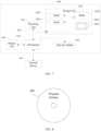
FIG. 8 is a structural schematic view of a computer-readable storage medium according to an embodiment of the present disclosure. - The following describes the implementation methods of the present disclosure through specific examples. Those skilled in the art can easily understand other advantages and effects of the present disclosure from the contents disclosed in the present disclosure. The present disclosure may also be implemented or applied through other specific implementation methods, and the details in the present disclosure may also be modified or changed in various ways according to different viewpoints and disclosure systems without departing from the spirit of the present disclosure. It should be noted that, in the absence of conflict, the embodiments and features in the embodiments of the present disclosure may be combined with each other.
- The following is a detailed description of the embodiments of the present disclosure with reference to the accompanying drawings, for those skilled in the art of the present disclosure to easily implement. The present disclosure can be embodied in many different forms and is not limited to the embodiments described herein.
- In the description of the present disclosure, terms such as "one embodiment", "some embodiments", "example", "specific example", or "some examples" means that the specific features, structures, materials or characteristics described in combination with the embodiment or example are included in at least one embodiment or example of the present disclosure. Furthermore, the particular features, structures, materials, or characteristics shown may be combined in any suitable manner in any one or more embodiments or examples. Furthermore, those skilled in the art may combine and associate different embodiments or examples and features of different embodiments or examples described in the present disclosure without mutual contradiction.
- In addition, the terms "first" and "second" are used for descriptive purposes only and cannot be understood as indicating or implying relative importance or implicitly indicating the quantity of the indicated technical features. Therefore, features defined as "first" or "second" may explicitly or implicitly refer to at least one of these features. In the description of the present disclosure, "multiple" means two or more, unless the number is clearly and specifically defined.
- To clearly describe the present disclosure, components not relative to the description are omitted, and the same reference numbers are used for the same or similar components throughout the description.
- Throughout the specification, when a certain device is described as be "connected" to another device, the connection may not only be "direct connection" but also "indirect connection" with other elements interposed therebetween. Furthermore, when a certain device is described as "including" a certain component, unless otherwise stated, the description does not exclude other components but means that other components may also be included.
- When a certain device is "on" another device, the certain device may be directly on the other device, or other devices may be interposed therebetween. By comparison, when a device is referred to as being "directly on" another device, there are no intervening devices.
- Although the terms first, second, etc. are used herein to refer to various elements in some examples, these elements should not be limited by these terms. These terms are only used to distinguish one element from another. For example, a first interface and a second interface are indicated. Furthermore, as used herein, the singular forms "a", "an" and "the" are intended to include the plural forms as well, unless the context indicates otherwise. It should be further understood that the terms "comprises" and "includes" indicate the existence of features, steps, operations, elements, components, items, types, and/or groups, but do not exclude the existence, occurrence, or addition of one or more other features, steps, operations, elements, components, items, types, and/or groups. The terms "or" and "and/or" used herein are to be interpreted as inclusive, or including any one or any combination. Thus, "A, B or C" or "A, B and/or C" means "any of the following: A; B; C; A and B; A and C; B and C; A, B and C." An exception to this definition only occurs when a combination of elements, functions, steps or operations are inherently mutually exclusive in some cases.
- The technical terms used herein are only used to refer to specific embodiments and are not intended to limit the present disclosure. The singular form used herein also includes the plural form unless the description clearly indicates otherwise. The term "comprising" as used in the description means to specify certain characteristics, regions, integers, steps, operations, elements and/or components, but does not exclude the existence or addition of other characteristics, regions, integers, steps, operations, elements and/or components.
- Although not defined differently, all terms, including technical and scientific terms used herein, have the same meaning as generally understood by one of those skilled in the art of the present disclosure. Terms defined in commonly used dictionaries are additionally interpreted as having a meaning consistent with the content of the relevant technical literature and the current disclosure, and unless otherwise defined, shall not be overly interpreted as having an ideal or very formal meaning.
-
FIG. 1 is a schematic view of a vehicle-mounted battery pack locking system of the present disclosure.FIG. 2 is a schematic view of the vehicle-mounted battery pack locking system and a battery pack in an unlocked state of the present disclosure.FIG. 3 is an enlarged view of A area inFIG. 2 .FIG. 4 is a schematic view of the vehicle-mounted battery pack locking system and a battery pack in a locked state of the present disclosure.FIG. 5 is an enlarged view of B area inFIG. 4 . As shown inFIGS. 1-5 , the vehicle-mounted battery pack locking system of the present disclosure is particularly suitable for large new energy vehicles equipped with large battery packs. The vehicle-mounted battery pack locking system includes: a battery swap passage and at least two lockingcomponents 3. The battery swap passage allows thebattery pack 4 to enter and exit thebattery position 2 of the battery swap vehicle 1 along a first direction. A group of connectingrods 41 parallel to the first direction are arranged at the bottom of thebattery pack 4. At least onesecond wedge block 42 is provided at each of two ends of each connectingrod 41. The wedge-shaped slope of thesecond wedge block 42 extends along the first direction. Fourlocking assemblies 3 are respectively arranged at two ends of thebattery position 2 along the first direction. Each lockingassembly 3 at least includes afirst wedge block 31, alimit slider 32 and a linear limit assembly respectively arranged on the lockingassembly 3 and a vehicle body of the battery swap vehicle 1. Thelimit slider 32 is limited to linearly moveable only along the first direction. Thefirst wedge block 31 is connected to one side of thelimit slider 32. Thelimit sliders 32 at the two ends are respectively pushed toward thebattery pack 4 by a bias force. The wedge-shapedslope 38 of thefirst wedge block 31 is respectively fitted and self-locked with the correspondingsecond wedge block 42, to bidirectionally limit the position of the battery pack along the first direction. Asecond wedge block 42 is respectively provided at each of the two ends of each connectingrod 41, the slope surface of thesecond wedge block 42 faces upward, the slope surface of thefirst wedge block 31 faces downward, and the first direction is a width direction of the battery-swap vehicle 1. The slope surface of thefirst wedge block 31 and the slope surface of thesecond wedge block 42 are in surface contact and self-locked with each other, converting a locking force of thelimit slider 32 along the first direction into a downward pressure that presses thebattery pack 4 against a bottom plate of thebattery position 2, thereby limiting thebattery pack 4 to thebattery position 2 between the second wedge blocks 42 at the two ends. The first direction is the width direction of the battery swap vehicle 1. The linear limit assembly includes adovetail groove 33 arranged at a bottom portion of thelimit slider 32 and adovetail tenon 37 fixed in thebattery position 2 in the vehicle body. Thedovetail groove 33 is slidable in thedovetail tenon 37 along a first direction. The first direction (Y direction, a width direction of the vehicle body) is perpendicular to the length direction (X direction, a length direction of the vehicle body) of the battery-swap vehicle 1. When swapping the battery pack through the vehicle-mounted battery pack locking system of the present disclosure, abattery swap robot 5 takes out thebattery pack 4 from acontainer battery compartment 6, and inserts thebattery pack 4 into thebattery position 2 of the battery swap vehicle 1 along the width direction of the vehicle body, and firmly locks thebattery pack 4 in thebattery position 2 with the lockingassembly 3 to prevent the battery pack from shaking in the vertical direction, the length direction and the width direction of the vehicle when the vehicle is driving. Wherein, the present disclosure can prevent thelimit slider 32 from moving in the vertical direction and the length direction of the vehicle through the cooperation between thedovetail groove 33 at the bottom portion of thelimit slider 32 and thedovetail tenon 37 fixed to thebattery position 2 in the vehicle body, in combination with the bias force and the self-locking between thewedge slope 38 of thefirst wedge block 31 and thesecond wedge block 42. The wedge angle of thewedge slope 38 and the slope of thesecond wedge block 42 in the present disclosure ranges from 3° to 6° (but not limited to this). The mutual cooperation of the two wedge surfaces at such an angle realizes a self-locking function, thereby effectively preventing thelimit slider 32 from moving in the width direction of the vehicle, thereby realizing the spatial locking of thebattery pack 4. - In a selective embodiment, when the
cylinder 34 pulls thelimit slider 32 toward thesecond wedge block 42, thecylinder 34 and thespring 36 together provide a combined force to limit thebattery pack 4, but the present disclosure is not limited to this. - In a selective embodiment, the locking
assembly 3 further includes acylinder 34 configured to drive thelimit slider 32 to move along the first direction through acylinder rod 35. The lockingassembly 3 further includes aspring 36 for pushing thelimit slider 32 toward thesecond wedge block 42 of thebattery pack 4. Thespring 36 and thecylinder 34 are respectively distributed on two sides of thelimit slider 32 along the first direction. Through the mutual cooperation between the wedge-shapedslope 38 of thefirst wedge block 31 and the slope of thesecond wedge block 42, the real-time locking force of thelimit slider 32 along the first direction (which can be a combined force provided by thecylinder 34 and thespring 36 to limit thebattery pack 4, or only the thrust of the limitingbattery pack 4 provided by the spring 36) is converted into a downward pressure that presses thebattery pack 4 against the bottom plate of thebattery position 2. In the present disclosure, thefirst wedge block 31 can firmly press thefirst wedge block 31 through the mechanical power of thecylinder 34 and the biasing force provided by thespring 36, thereby realizing a double locking function. In this embodiment, due to the mutual cooperation between thefirst wedge block 31 and thesecond wedge block 42, when thecylinder 34 further increases the pulling force on thelimit slider 32, the cooperation between the wedge blocks will provide a greater downward pressure to thebattery pack 4, ensuring that thebattery pack 4 is fixed in thebattery position 2. - In a selective embodiment, when the
cylinder 34 overcomes the thrust of thespring 36 and pushes thelimit slider 32 away from thesecond wedge block 42, thebattery position 2 is in an unlocked state for inserting or removing thebattery pack 4, but the present disclosure is not limited to this. - In a selective embodiment, the
limit sliders 32 are located on outer sides of the connectingrods 41, the first wedge blocks 31 are located on inner sides of thelimit sliders 32, and moving strokes of the first wedge blocks 31 are located on extension lines of the two ends of the connectingrods 41, but the present disclosure is not limited to this. - In a selective embodiment, the
battery position 2 is further provided with at least two positioning guide rods (not shown in the drawings) extending vertically upward, and thebattery pack 4 is first positioned in the vertical direction through the cooperation of vertical through holes (not shown in the drawings) of thebattery pack 4 and the positioning guide rods, and then falls to the bottom of thebattery position 2, and then thelimit sliders 32 on two sides of the bottom of thebattery position 2 clamp thesecond wedge block 42 after being horizontally moved to fix the horizontal position of thebattery pack 4. Through the cooperation among the vertical through holes, the positioning guide rods, thelimit sliders 32 and thesecond wedge block 42, thebattery pack 4 is completely fixed on thebattery position 2 in the three-dimensional directions. At this time, the displacement of thebattery pack 4 in each of the three-dimensional directions relative to thebattery position 2 is 0. - The vehicle-mounted battery pack locking system of the present disclosure can spatially lock the battery pack and provide double locking protection in the insertion direction of the battery pack, which can not only be unlocked quickly, but also provide a strong locking effect. The
cylinder 34 can drive thefirst wedge block 31 to perform a single reciprocating motion along thedovetail groove 33. Thedovetail groove 33 not only guides thefirst wedge block 31, but also can bear a lateral force to prevent thefirst wedge block 31 from separating from thedovetail groove 33. Furthermore, under the action of thecylinder 34, thefirst wedge block 31 and thesecond wedge block 42 fit closely together, thus locking the battery pack. The wedge clamping structure is widely applied as having a simple structure, a large force amplification ratio and a good self-locking performance. When thecylinder 34 fails and cannot provide the pulling force, thefirst wedge block 31 can still firmly press thesecond wedge block 42 under the rebound force of the spring 36 (for example, a compression spring). Therefore, the system has a double locking function. - Based on the above technical features, the vehicle-mounted battery pack locking system of the present disclosure has the following advantages.
- 1. The system needs simple power as being driven by a cylinder.
- 2. The structure is simple and arranged horizontally, requiring little mounting space.
- 3. The dovetail groove design is adopted to effectively prevent loosening.
- 4. The action is simple and the battery pack is locked with a single horizontal movement.
- 5. Double protection is adopted, that is, a mechanical locking mechanism is added. Even if the cylinder fails, the battery pack can still be locked through the rebound force of the spring.
-
FIG. 6 is a flow chart of a method for locking a vehicle-mounted battery pack according to the present disclosure. As shown inFIG. 6 , the vehicle-mounted battery pack locking method of the present disclosure is realized by the above-mentioned vehicle-mounted battery pack locking system and includes the following steps: - S100, limiting the
battery pack 4 at thebattery position 2 by a guide member (for example, a positioning guide rod) along a vertical direction. - S110, the
first wedge block 31 of the lockingassembly 3 overcoming the biasing force and respectively separating from the second wedge blocks 42 at the two ends of thebattery pack 4 to unlock. - S120, lifting the
battery pack 4 to separate from thebattery position 2. - S130, placing another
battery pack 4 into thebattery position 2. and - S140, pressing the
first wedge block 31 of the lockingassembly 3 against the second wedge blocks 42 at the two ends of thebattery pack 4, and limiting thebattery pack 4 to thebattery position 2 together with the bias force. - As shown in
FIGS. 1-5 , the main process of implementing the vehicle battery pack locking method of the present disclosure is as follows. - When the battery pack is unlocked, the
cylinder 34 provides a thrust to overcome the elastic force of thespring 36, so that thefirst wedge block 31 and thesecond wedge block 42 are separated. The battery-swappingrobot 5 lifts thebattery pack 4 to separate from thebattery position 2, then carries another fully-chargedbattery pack 4 into thebattery position 2 and puts thebattery pack 4 down. When thebattery pack 4 falls into thebattery position 2 on the vehicle base, the system recognizes the signal and sends a command to thecylinder 34 to operate. Themovable wedge block 4 is pulled toward the cylinder, and thefirst wedge block 31 and thesecond wedge block 42 fit tightly. In this embodiment, when the wedge angle of the wedge surfaces is less than 4.5 degrees, the wedge surfaces are self-locked. In addition, the spring at the end maintains an elastic state, thereby realizing a double locking function. Assuming that thecylinder 34 fails and cannot provide a pulling force, under the action of the restoring force of thespring 36, thefirst wedge block 31 can still be firmly pressed against thesecond wedge block 42. - The vehicle-mounted battery pack locking method of the present disclosure can spatially lock the battery pack and provide double locking protection in the insertion direction of the battery pack, which can not only be unlocked quickly, but also provide a strong locking effect.
- The present disclosure further provides a vehicle-mounted battery pack locking device including: a processor; a memory configured to store executable instructions of the processor. Wherein the processor is configured to execute the steps of the vehicle-mounted battery pack locking method by executing executable instructions.
- As stated above, the vehicle-mounted battery pack locking method of the present disclosure can spatially lock the battery pack and provide double locking protection in the insertion direction of the battery pack, which can not only be unlocked quickly, but also provide a strong locking effect.
- Those skilled in the art can understand that various aspects of the present disclosure can be implemented as a system, a method, or a program product. Therefore, various aspects of the present disclosure may be specifically implemented in the form of: a complete hardware implementation, a complete software implementation (including firmware, microcode, etc.), or a combination of hardware and software implementations, which may be collectively referred to herein as "circuit", "module" or "platform".
-
FIG. 7 is a structural schematic view of a vehicle-mounted battery pack locking device according to the embodiment of the present disclosure. Theelectronic device 600 according to this embodiment of the present disclosure will be described below with reference toFIG. 7 . Theelectronic device 600 shown inFIG. 7 is only an example, and should not imply any limitation to the functions and usage scope of the embodiments of the present disclosure. - As shown in
FIG. 7 , theelectronic device 600 is represented in the form of a general-purpose computing device. The components of theelectronic device 600 may include, but are not limited to: at least oneprocessing unit 610, at least onestorage unit 620, and abus 630 connecting different system components (including thestorage unit 620 and the processing unit 610). - In an embodiment, the storage unit stores program codes which, when being executed by the
processing unit 610, causes theprocessing unit 610 to implement steps of various exemplary embodiments described in the forgoing part describing the vehicle-mounted battery pack locking method of the description. For example, theprocessing unit 610 may be configured to perform, as shown inFIG. 6 . - The
storage unit 620 may include a readable medium in the form of a transitory storage unit, such as a random access storage unit (RAM) 6201 and/or a high-speedcache storage unit 6202, and may further include a read-only storage unit (ROM) 6203. - The
storage unit 620 may further include a program/utility tool 6204 having a set of (at least one)program module 6205.Such program module 6205 includes, but not limited to, an operating system, one or more disclosure programs, other program modules, and program data. Each of these examples or some combination thereof may include an implementation of network environment. - The
bus 630 may be one or more of several types of bus structures, including a storage unit bus or a storage unit controller, a peripheral bus, a graphics acceleration port, a processing unit, or a local area using any of a variety of bus structures bus. - The
electronic device 600 may also communicate with one or more external devices 700 (e.g., keyboard, pointing device, Bluetooth device, etc.), and may also communicate with one or more devices that enable a user to interact with theelectronic device 600, and/or any device (e.g., router, modem, etc.) that enables theelectronic device 600 to communicate with one or more other computing devices. This communication can be performed through an input/output (I/O)interface 650. Moreover, theelectronic device 600 can also communicate with one or more networks (e.g., local area network (LAN), wide area network (WAN), and/or a public network such as the Internet) through anetwork adapter 660. As shown in the drawing, thenetwork adapter 660 communicates with other modules of theelectronic device 600 through thebus 630. It should be understood that, although not shown in the drawing, other hardware and/or software modules may be used in conjunction with theelectronic device 600, including but not limited to, microcode, device driver, redundant processing unit, external disk drive array, RAID system, tape driver and data backup storage system. - The embodiment of the present disclosure further provides a computer-readable storage medium on which a program product capable of implementing the above method of the disclosure is stored. In some possible implementation manners, various aspects of the present disclosure may also be implemented in the form of a program product, including program code which, when being executed by a terminal device, causes the terminal device to implement steps of various exemplary embodiments described in the forgoing vehicle-mounted battery pack locking method.
- When the program in the computer-readable storage medium is executed, the point cloud information of LiDAR and the image information of camera can be fully utilized, and the shortcomings of existing technology that cannot combine a fast recognition speed and high accuracy can be overcome. The present disclosure realizes real-time 3D target detection with higher accuracy, and significantly improves the detection accuracy of small targets. The present disclosure increases the speed and accuracy of 3D target recognition, which helps to provide safer and more reliable environmental perception information for unmanned vehicles.
-
FIG. 8 is a structural schematic view of a computer-readable storage medium according to the embodiment of the present disclosure. Referring toFIG. 8 , aprogram product 800 for implementing the above method according to an embodiment of the present disclosure is described. It may be implemented using a portable compact disk read-only memory (CD-ROM) and include a program code, and may be executed by a terminal device, for example, a personal computer. However, the program product of the present disclosure is not limited thereto. In the present disclosure, the readable storage medium may be any tangible medium containing or storing a program, which may be used by or in combination with an instruction execution system, apparatus, or device. - The program product may employ any combination of one or more readable medium. The readable medium may be a readable signal medium or a readable storage medium. The readable storage medium may be, for example but not limited to, an electrical, magnetic, optical, electromagnetic, infrared, or semiconductor system, apparatus, or device, or any combination thereof. More specific examples of readable storage medium (non-exhaustive list) may include: electrical connections with one or more wires, portable disks, hard disks, random access memory (RAM), read-only memory (ROM), erasable programmable read-only memory (EPROM or flash memory), optical fiber, portable compact disk read-only memory (CD-ROM), optical storage device, magnetic storage device, or any suitable combination of the foregoing.
- The computer-readable signal medium may include a data signal that is transmitted in baseband or as part of a carrier wave, in which readable program code is carried. This transmitted data signal can take many forms, including but not limited to electromagnetic signals, optical signals, or any suitable combination of the above. The readable signal medium may also be any readable medium other than a readable storage medium, and the readable medium may send, propagate, or transmit a program for use by or in combination with an instruction execution system, apparatus, or device. The program code contained on the readable medium may be transmitted using any appropriate medium, including but not limited to wireless, wired, optical fiber cable, RF, etc., or any suitable combination of the foregoing.
- The program code for performing the operations of the present disclosure may be written in any combination of one or more programming languages, which may include a target-oriented programming language, such as the Java and C++, or may include conventional formula programming language, such as "C" language or similar programming language. The program code may be entirely executed on the user computing device, partly executed on the user device, executed as an independent software package, partly executed on the user computing device and partly executed on a remote computing device, or entirely executed on the remote computing device or server. In situations involving a remote computing device, the remote computing device may be connected to the user computing device through any kind of network, including a local area network (LAN) or a wide area network (WAN), or may be connected to an external computing device (e.g., through connection via the Internet using Internet service provider).
- Above all, the purpose of the present disclosure is to provide a vehicle-mounted battery pack locking system, a method, a device, and a storage medium, that can spatially lock the battery pack and provide double locking protection in the insertion direction of the battery pack, unlock the battery quickly and provide strong locking effect.
- The above is a detailed description of the present disclosure in connection with the specific preferred embodiments, and the specific embodiments of the present disclosure are not limited to the description. Modifications and substitutions can be made without departing from the scope of the present disclosure.
Claims (12)
- A vehicle-mounted battery pack locking system comprising:a battery swap passage for a battery pack to enter and exit a battery position of a battery swap vehicle along a first direction, wherein at least one second wedge block is provided at each of two ends of the battery pack, and a wedge-shaped slope of the second wedge block is configured to extend along the first direction; andat least two locking assemblies respectively arranged at two ends of the battery position along the first direction, wherein each locking assembly at least includes one limit slider and a first wedge block, the limit slider is limited to be linearly movable only along the first direction, the first wedge block is connected to one side of the limit slider, the limit sliders at the two ends of the battery position are pushed toward the battery pack by a bias force, and a wedge-shaped slope of each first wedge block is respectively fitted and self-locked with the corresponding second wedge block, to bidirectionally limit the position of the battery pack along the first direction.
- The vehicle-mounted battery pack locking system of claim 1, wherein a group of connecting rods arranged parallel to the first direction are provided at a bottom portion of the battery pack, and the second wedge blocks are respectively provided at two ends of each connecting rod, the slope of the second wedge block faces upward, and the slope of the first wedge block faces downward, the slope of the first wedge block is in surface contact with the slope of the second wedge block to fit together for self-locking, a locking force of the limit slider along the first direction is converted into a downward pressure that presses the battery pack against a bottom plate of the battery position, so that the battery pack is limited to the battery position between the second wedge blocks at the two ends of the battery position, and the first direction is a width direction of the battery swap vehicle.
- The vehicle-mounted battery pack locking system of claim 2, wherein the locking assembly further includes linear limit assemblies respectively arranged on the locking assemblies and a vehicle body of the battery swap vehicle.
- The vehicle-mounted battery pack locking system of claim 3, wherein the linear limit assembly includes a dovetail groove arranged at a bottom portion of the limit slider and a dovetail tenon fixed at the battery position in the vehicle body, and the dovetail groove is slidable in the dovetail tenon along the first direction.
- The vehicle-mounted battery pack locking system of claim 2, wherein the locking assembly further includes a cylinder configured to drive the limit slider to move along the first direction through a cylinder rod.
- The vehicle-mounted battery pack locking system of claim 5, wherein the locking assembly further includes a spring configured to push the limit slider toward the second wedge block of the battery pack, wherein the spring and the cylinder are respectively arranged on two sides of the limit slider along the first direction.
- The vehicle-mounted battery pack locking system of claim 6, wherein when the cylinder overcomes a thrust of the spring and pushes the limit slider away from the second wedge block, the battery position is in an unlocked state for inserting or removing the battery pack.
- The vehicle-mounted battery pack locking system of claim 6, wherein when the cylinder pulls the limit slider toward the second wedge block, the cylinder and the spring together provide a combined force to limit the battery pack.
- The vehicle-mounted battery pack locking system of claim 2, wherein the limit sliders are respectively located on outer sides of the connecting rods, the first wedge blocks are respectively located on inner sides of the limit sliders, and moving strokes of the first wedge blocks are respectively located on extension lines of the two ends of the connecting rods.
- A vehicle-mounted battery pack locking method realized by the vehicle-mounted battery pack locking system of claim 1, wherein the method comprises:limiting the battery pack to the battery position by a guide member extending along a vertical direction;the first wedge blocks of the locking assemblies overcoming the bias force and respectively separating from the second wedge blocks at the two ends of the battery pack to unlock the battery pack;lifting the battery pack to separate from the battery position;placing another battery pack into the battery position; andpressing the first wedge blocks of the locking assemblies against the second wedge blocks at the two ends of the battery pack, and limiting the battery pack to the battery position together with the bias force.
- A vehicle-mounted battery pack locking device comprising:a processor;a memory configured to store executable instructions of the processor;wherein the processor is configured to execute the steps of the vehicle-mounted battery pack locking method of claim 10 by executing the executable instructions.
- A computer-readable storage medium used for storing program, wherein the vehicle-mounted battery pack locking method of claim 10 is realized when the program is executed by a processor.
Applications Claiming Priority (2)
| Application Number | Priority Date | Filing Date | Title |
|---|---|---|---|
| CN202210255679.3A CN114701343B (en) | 2022-03-15 | 2022-03-15 | Vehicle-mounted battery pack locking system, method, equipment and storage medium |
| PCT/CN2022/133466 WO2023173795A1 (en) | 2022-03-15 | 2022-11-22 | Vehicle-mounted battery pack locking system, method and device, and storage medium |
Publications (2)
| Publication Number | Publication Date |
|---|---|
| EP4494907A1 true EP4494907A1 (en) | 2025-01-22 |
| EP4494907A4 EP4494907A4 (en) | 2025-07-23 |
Family
ID=82168753
Family Applications (1)
| Application Number | Title | Priority Date | Filing Date |
|---|---|---|---|
| EP22931806.8A Pending EP4494907A4 (en) | 2022-03-15 | 2022-11-22 | VEHICLE-MOUNTED BATTERY PACK LOCKING SYSTEM, METHOD AND APPARATUS, AND STORAGE MEDIUM |
Country Status (3)
| Country | Link |
|---|---|
| EP (1) | EP4494907A4 (en) |
| CN (1) | CN114701343B (en) |
| WO (1) | WO2023173795A1 (en) |
Families Citing this family (2)
| Publication number | Priority date | Publication date | Assignee | Title |
|---|---|---|---|---|
| CN114701343B (en) * | 2022-03-15 | 2025-12-23 | 上海西井科技股份有限公司 | Vehicle-mounted battery pack locking system, method, equipment and storage medium |
| CN115117480A (en) * | 2022-07-06 | 2022-09-27 | 上海西井信息科技有限公司 | Collecting card battery replacing bag and battery replacing method thereof |
Family Cites Families (13)
| Publication number | Priority date | Publication date | Assignee | Title |
|---|---|---|---|---|
| CN105083236B (en) * | 2015-05-29 | 2017-08-29 | 谢子聪 | Control system for replacing power battery of electric passenger vehicle |
| CN105584346B (en) * | 2016-03-16 | 2017-12-12 | 杭州莱本科技有限公司 | Fast changing battery self-locking device and the vehicle with the fast changing battery self-locking device |
| DE102016225662A1 (en) * | 2016-12-20 | 2018-06-21 | Volkswagen Aktiengesellschaft | Fastening arrangement on a battery housing and battery housing with such a fastening arrangement |
| CN209981303U (en) * | 2019-05-06 | 2020-01-21 | 上海蔚来汽车有限公司 | Battery pack clamping device, battery bin and battery replacing system |
| CN110614935A (en) * | 2019-07-12 | 2019-12-27 | 北自精工机械(常州)有限公司 | Lock body assembly and automobile battery quick locking device with same |
| CN211684629U (en) * | 2019-10-24 | 2020-10-16 | 北京新能源汽车股份有限公司 | Locking subassembly, installation device and vehicle |
| WO2021128826A1 (en) * | 2019-12-25 | 2021-07-01 | 上海玖行能源科技有限公司 | Battery-replaceable load-bearing motion apparatus |
| CN111204254A (en) * | 2020-01-20 | 2020-05-29 | 浙江吉智新能源汽车科技有限公司 | Battery pack locking mechanism, battery pack unlocking mechanism, battery pack and vehicle |
| CN215042022U (en) * | 2021-02-04 | 2021-12-07 | 博众精工科技股份有限公司 | Vehicle-mounted battery assembly and electric vehicle |
| CN113043906B (en) * | 2021-05-12 | 2024-04-26 | 安徽华菱汽车有限公司 | Electricity changing type pure electric heavy-duty card electricity changing system structure |
| CN113183823B (en) * | 2021-06-01 | 2022-08-12 | 常州科研试制中心有限公司 | Battery replacement system and method for mining explosion-proof electric vehicle |
| CN217197757U (en) * | 2022-03-15 | 2022-08-16 | 上海西井信息科技有限公司 | Vehicle-mounted battery pack locking system |
| CN114701343B (en) * | 2022-03-15 | 2025-12-23 | 上海西井科技股份有限公司 | Vehicle-mounted battery pack locking system, method, equipment and storage medium |
-
2022
- 2022-03-15 CN CN202210255679.3A patent/CN114701343B/en active Active
- 2022-11-22 EP EP22931806.8A patent/EP4494907A4/en active Pending
- 2022-11-22 WO PCT/CN2022/133466 patent/WO2023173795A1/en not_active Ceased
Also Published As
| Publication number | Publication date |
|---|---|
| WO2023173795A1 (en) | 2023-09-21 |
| EP4494907A4 (en) | 2025-07-23 |
| CN114701343A (en) | 2022-07-05 |
| CN114701343B (en) | 2025-12-23 |
Similar Documents
| Publication | Publication Date | Title |
|---|---|---|
| EP4494907A1 (en) | Vehicle-mounted battery pack locking system, method and device, and storage medium | |
| EP3955039B1 (en) | Blind mate thermal cooling solution for small form factor pluggable transceiver | |
| DE202021004381U1 (en) | Battery pack, vehicle and electronic device with such a pack | |
| US20220274488A1 (en) | Battery architecture without low voltage battery | |
| CN217740666U (en) | Battery pack and electronic device | |
| US7646613B2 (en) | Multi-point latch mechanism with a single control | |
| CN217197757U (en) | Vehicle-mounted battery pack locking system | |
| HK40074944A (en) | Locking system, method, device and storage medium for vehicle battery packs | |
| HK40074944B (en) | Locking system, method, device and storage medium for vehicle battery packs | |
| CN108751040A (en) | A kind of vehicle-mounted synchronization lifting mechanisms of AGV and AGV vehicles | |
| US12610494B2 (en) | Chassis and electronic host | |
| EP3751635B1 (en) | Battery package including fixing member, a device including the same and manufacturing method of battery package | |
| CN114872570A (en) | Charging mechanism, power receiving mechanism and charging method | |
| CN105059920A (en) | Air-suction type sample storing and taking device | |
| CN216619037U (en) | Screen linear movement device and mobile terminal | |
| CN118249030A (en) | Battery module and electric equipment | |
| CN109114066B (en) | Actuating cylinder | |
| CN207985173U (en) | A kind of good unmanned plane undercarriage of cushion performance | |
| CN110856071B (en) | TWS earphone system, TWS earphone and earphone charging box | |
| CN110722597A (en) | Band-type brake device | |
| CN213271682U (en) | Retractable server mounting rack | |
| CN222355284U (en) | Battery box and energy storage device thereof | |
| CN220306382U (en) | Battery packs and electrical devices | |
| CN214173113U (en) | Missile cabin way multi-degree-of-freedom butt joint device | |
| US20260058281A1 (en) | Power storage device and method for manufacturing the same |
Legal Events
| Date | Code | Title | Description |
|---|---|---|---|
| STAA | Information on the status of an ep patent application or granted ep patent |
Free format text: STATUS: THE INTERNATIONAL PUBLICATION HAS BEEN MADE |
|
| PUAI | Public reference made under article 153(3) epc to a published international application that has entered the european phase |
Free format text: ORIGINAL CODE: 0009012 |
|
| STAA | Information on the status of an ep patent application or granted ep patent |
Free format text: STATUS: REQUEST FOR EXAMINATION WAS MADE |
|
| 17P | Request for examination filed |
Effective date: 20241014 |
|
| AK | Designated contracting states |
Kind code of ref document: A1 Designated state(s): AL AT BE BG CH CY CZ DE DK EE ES FI FR GB GR HR HU IE IS IT LI LT LU LV MC ME MK MT NL NO PL PT RO RS SE SI SK SM TR |
|
| DAV | Request for validation of the european patent (deleted) | ||
| DAX | Request for extension of the european patent (deleted) | ||
| A4 | Supplementary search report drawn up and despatched |
Effective date: 20250625 |
|
| RIC1 | Information provided on ipc code assigned before grant |
Ipc: B60K 1/04 20190101AFI20250618BHEP Ipc: B60L 50/00 20190101ALI20250618BHEP Ipc: H01M 50/244 20210101ALI20250618BHEP Ipc: H01M 50/249 20210101ALI20250618BHEP Ipc: H01M 50/264 20210101ALI20250618BHEP |