EP4494792A1 - End mill tool - Google Patents
End mill tool Download PDFInfo
- Publication number
- EP4494792A1 EP4494792A1 EP23186588.2A EP23186588A EP4494792A1 EP 4494792 A1 EP4494792 A1 EP 4494792A1 EP 23186588 A EP23186588 A EP 23186588A EP 4494792 A1 EP4494792 A1 EP 4494792A1
- Authority
- EP
- European Patent Office
- Prior art keywords
- cutting
- cutting edge
- transition
- end mill
- mill tool
- Prior art date
- Legal status (The legal status is an assumption and is not a legal conclusion. Google has not performed a legal analysis and makes no representation as to the accuracy of the status listed.)
- Pending
Links
Images

Classifications
-
- B—PERFORMING OPERATIONS; TRANSPORTING
- B23—MACHINE TOOLS; METAL-WORKING NOT OTHERWISE PROVIDED FOR
- B23C—MILLING
- B23C5/00—Milling-cutters
- B23C5/02—Milling-cutters characterised by the shape of the cutter
- B23C5/10—Shank-type cutters, i.e. with an integral shaft
-
- B—PERFORMING OPERATIONS; TRANSPORTING
- B23—MACHINE TOOLS; METAL-WORKING NOT OTHERWISE PROVIDED FOR
- B23C—MILLING
- B23C2210/00—Details of milling cutters
- B23C2210/04—Angles
- B23C2210/0407—Cutting angles
-
- B—PERFORMING OPERATIONS; TRANSPORTING
- B23—MACHINE TOOLS; METAL-WORKING NOT OTHERWISE PROVIDED FOR
- B23C—MILLING
- B23C2210/00—Details of milling cutters
- B23C2210/54—Configuration of the cutting part
Definitions
- the present invention relates to a an end mill tool for metal cutting.
- an end mill comprises a plurality of cutting edges, which extend axially along the tool and radially along a front end of the tool.
- the teeth have front cutting edges that cut a surface in an axial forward feed direction, and side cutting edges that cut a surface in a radial feed direction.
- a front cutting edge typically extends radially outward from a center of the tool toward a corner portion. The corner portion of the cutting edge connects the front cutting edge with the side cutting edge.
- a problem with such known end mills is that the corner portion is prone to wear and damage such as notch wear and chipping.
- End mill tools or in other words end milling tools, that have both an axially forward cutting front edge and a radially cutting side edge are usually provided with a chamfer at the transition of the front edge to side edge.
- the chamfer removes a sharp corner at the transition.
- a new sharp corner is created on the front cutting edge at a small distance radially inward from the periphery.
- the present end mill tool according to invention thanks to the cutting edge, along the chamfer, having a rake surface with an axial rake angle that is less of equal to the helix angle of the front end of the chip flute at the transition, any new sharp corner due to the convex clearance surface is avoided.
- a transition cutting edge with a positive axial rake angle is made stronger to better withstand wear and chipping.
- the present invention relates to an end mill tool for metal cutting.
- the end mill tool comprises a body with a cutting head.
- the end mill tool is of a type wherein the cutting head is a one-piece integral unit with a shaft, sometimes called "solid round tools".
- the end mill tool is a exchangeable head and is connectable to a shaft.
- the shaft optionally has a coupling at the rear end.
- the cutting head is connectable to a machine spindle or to an adapter for a machine spindle.
- the machine spindle typically is part of a machine, for example a CNC machine.
- the end mill tool comprises a wear resistant material such as for example coated or non-coated cemented carbide, cermet, ceramic or CBN.
- the cutting head is elongated in the longitudinal direction.
- the axial length of the cutting head is equal or smaller, preferably larger, than the diameter of the cutting circle.
- the cutting teeth are provided in the front end of the cutting head, which each extend radially outward from a central region at the longitudinal axis and each present a mainly axially forward cutting front cutting edge.
- the front cutting edge of a specific cutting tooth extends from the longitudinal axis or a from a point a distance radially outward therefrom.
- the front cutting edge of a specific cutting tooth extends mainly along a radius or along a chord, wherein the cutting edge optionally is straight or curved.
- all front cutting edges extend from the same radial distance from the longitudinal axis, or, from different radial distances.
- a number of the cutting edges start at a first, same radial distance and a number start at a second, same radial distance, which is different from the first radial distance.
- the front end of the cutting head preferably is an axially forwardly facing end surface of the end mill tool.
- the cutting teeth continue axially rearward from a radially outer region of the front end and each present a mainly radially cutting side cutting edge.
- the side cutting edges cut radially only.
- the teeth typically extend along a peripheral surface of the body of the cutting head.
- the side cutting edge of each of the cutting teeth extends with an angle to the longitudinal axis and preferably form a helix.
- the axial extension of the side cutting edge rearward from the front end is for example less than, equal to or longer than the cutting diameter, and preferably 1 - 5 times the cutting diameter.
- the side cutting edges are continuous.
- the side cutting edges are interrupted by grooves. In applications, grooves are beneficial for reducing the breadth of cut chips, or for creating additional minor cutting edges.
- the cutting head comprises a plurality of chip flutes, which, rotationally in front of a respective one of the plurality of cutting teeth, each extends axially rearward from the front end.
- the chip flutes typically extend along the peripheral surface of the body of the cutting head.
- Each chip flute extends with an angle to the longitudinal axis and preferably forms a helix.
- the angle is denominated "helix angle" also for chip flutes that are angled without forming a helix and is to be understood as the angle between a bottom of the chip flute and the longitudinal axis.
- the helix angle of a specific side cutting edge is equal to helix angle of the chip flute that is rotationally in front thereof.
- the helix angle of the chip flutes varies or is constant, for example, the helix angle decreases or increases axially rearward from the front end.
- the helix angle at the front end of the chip flute which is rotationally in front of the transition cutting edge, is at least 10° and at most 60°, preferably, at least 20° and at most 50°. Within this range, the chip flutes provide satisfactory chip evacuation and/or chip breaking for most applications.
- Each cutting edge of the plurality of teeth further comprises a transition cutting edge extending from the front cutting edge to the side cutting edge.
- the transition cutting edge has a radially inner end at the front end connecting to the front cutting edge and an axially rear end connecting to the side cutting edge at an axial front end of the side cutting edge.
- the transition cutting edge extends over the radially outer corner where the peripheral side surface meets the front end surface of the cutting head body.
- Each chip flute has a front end, which is a portion of the chip flute that is located at the corner portion with the transition cutting edge.
- the transition cutting edge extends at least partly along a chamfer in form of a clearance surface.
- the clearance surface of the translon cutting edge is convex in a direction of the extension of the transition cutting edge, i.e. in a radial direction along the front end.
- the convex curvature of the clearance surface can be seen in a plane that is normal to a tangent of a circle cut by a point on the transition cutting edge when the tool is rotated without feed.
- the clearance surface extends at a constant clearance angle.
- the axial rake angle along the side cutting edge is 0°.
- the axial rake angle is positive, and equal or less than the helix angle at the front end of the chip flute which is rotationally in front thereof.
- the axial rake angle is considered positive when the rake surface is inclined rotationally rearward in a direction axially rearward.
- the axial rake angle is maximally 10° less than the helix angle. Thereby it is ensured that the transition cutting edge is sufficiently smooth for most applications. For example, any corners are obtuse with having an angle of at least 170°.
- the axial rake angle is chosen such that the transition cutting edge is continuously curved.
- the front cutting edge comprises a central portion extending radially outward from the central region at the longitudinal axis, and a peripheral portion, extending radially outward from an inner end at the central portion to an outer end at the transition cutting edge.
- the axial rake angle transitions form the axial rake angle of the transition cutting edge at the outer end to the axial rake angle of the central portion at the inner end.
- the front cutting edge can be given any desired axial rake angle at the central portion without introducing sharp corners.
- the axial rake angle ⁇ is constant. Thereby grinding of the axial rake angle is easier.
- the transition of the axial rake angle of the peripheral portion is continuous.
- the transition cutting edge and the peripheral portion of the front cutting edge are continuous, for example continuously curved or straight.
- the axial rake angle of the central portion of the front cutting edge is constant. Thereby the grinding of the rake surface is easier.
- the axial rake angle of the central portion of the front cutting edge is positive.
- the axial rake angle is at least 5° and at most 30°. Large, positive rake angles provide a more pointed cutting edge which lowers cutting forces and heat generation. Smaller positive rake angles provide a blunter cutting edge, which is stronger an advantageous when cutting harder materials.
- the cutting head further comprises a web, wherein as seen in a front end view, the inner end of the peripheral portion of the front cutting edge is located at the intersection of the chip flute and the web.
- the grinding wheel is progressively tilted along the peripheral cutting edge. If the peripheral portion of the front cutting edge is outside of the web, such progressive tilting is easier as compared to griding inside the web.
- the space cut by the grinding wheel in the web is sometimes referred to as "gash".
- the inner end of the peripheral portion is located a radial distance of at least 25% and at most 30% of the cutting diameter from the cutting circle. It is easier to grind the changing rake surface at a distance from the center.
- the location of the inner end of the peripheral portion is also to the location of the outer end of the central portion of the front cutting edge.
- the outer end of the peripheral portion is located a radial distance of at least 37.5% and at most 42,5% of the cutting diameter from the longitudinal axis.
- the end mill tool is square end mill tool, a chamfer end mill tool, a tapered end mill tool or a corner end mill tool.
- a front end of the side cutting edge is located a distance of at most 5% of the cutting diameter axially rearward of a most forward front point of the cutting head.
- the most forward point is a radially outer point of a cutting edge or a tool tip at the central longitudinal axis.
- the most forward point may also be any point on a front cutting edge without axial extension.
- a corner radius of the transition cutting edge is less than 25% diameter of the cutting circle.
- the inventive axial rake angle of the transition cutting edge is especially advantageous for such tools. Due to a relative axially short corner portion of such tools, the transition edges with a small radius of curvature tend to be more prone to wear and chipping, especially at sharp corners introduced in the front cutting edge when gridding the chamfer/clearance surface.
- the front cutting edges may in embodiments have an inclination relative the longitudinal axis so that they cut a short axial distance in addition to their mainly axially forward cutting direction.
- two or more of the cutting edges meet in the axially most forward point forming a tip.
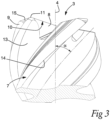
- the square end mill tool comprises a body 1, with a cutting head 2.
- the cutting head 2 has a front end 3, which is also the front end of the square end mill tool, and a central longitudinal axis 4 extending rearward from the front end 3.
- the front end 3 of the cutting head 2 is an axially forwardly facing end surface of the square end mill tool.
- the axis 4 is the central longitudinal axis of the square end mill tool.
- the square end mill tool has a rear end 5 at the axially opposite end to the front end 3.
- the cutting head comprises a plurality of cutting teeth 7, which each has a cutting edge formed at an intersection of a respective rake surface 8 and a respective clearance surface 9.
- the square end mill tool according to the embodiment comprises four cutting teeth 7.
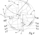
- the cutting edges each has radially most outer point at the same radial distance from the longitudinal axis 4.
- the cutting head 2 defines a cutting circle 12 formed by radially most outer points of the cutting edges when the square end mill tool is rotated one turn around the longitudinal axis 4 without being fed in any direction.
- the cutting circle 12 has a cutting diameter, which in the shown embodiment is 10 mm.
- Each tooth 7 presents a mainly axially forward cutting front cutting edge 10, wherein each front cutting edge 10 extends radially outward from a central region at the longitudinal axis 4. Two of the front the cutting edges 10 start at a same, first radial distance close to longitudinal axis 4, and the other two of the four front cutting edges 10 start at a same, second radial distance from the longitudinal axis 4, wherein the second radial distance is larger than the first radial distance.
- Each of the four front cutting edges 10 extend at the side of the longitudinal axis 4 generally along a chord of the cutting circle 12. Each front cutting edge 10 is straight both when viewed in a front end vies and in a side view, c.f. Fig. 4 and 3 , respectively.
- Each tooth 7 continues axially rearward from a radially outer region of the front end 2 and presents a mainly only radially cutting side cutting edge 14, which extend axially rearward from the front end 3 along a peripheral surface of the body of the cutting head 2.
- the side cutting edge 14 of each of the cutting teeth 7 extends with an angle to the longitudinal axis and forms a helix.
- the cutting head 2 comprises a plurality of chip flutes 13, which extend axially rearward from the front end 3 along a peripheral surface of the body of the cutting head 2. Each chip flute 13 extends rotationally in front of a respective one of the plurality of cutting teeth 7.
- Each chip flute 13 forms a helix and extends with an angle in form of a helix angle ⁇ to the longitudinal axis 4.
- the helix angle ⁇ is measured as the angle between a bottom of the chip flute 13 and the longitudinal axis, c.f. Fig. 3 .
- the helix angle of a side cutting edge 14 is equal to helix angle ⁇ of the chip flute that is rotationally in front thereof.
- Each cutting edge of the plurality of teeth 7 further comprises a transition cutting edge 11, which extends over the radially outer corner where the peripheral side surface meets the front end surface of the cutting head 2, c.f. Fig. 4 .
- the transition cutting edge 11 has a radially inner end connecting to the front cutting edge 10 and an axially rear end connecting to the side cutting edge 14.
- Each chip flute 13 has a front end, which is a portion of the chip flute that is located at the corner portion with the transition cutting edge.
- the helix angle ⁇ is the same for all chip flutes 13, and also constant along the axial length including the front end.
- the helix angle ⁇ is 48°.
- the transition cutting edge 11 extends at least partly along a chamfer 15 in form of a clearance surface 9.
- the clearance surface 15 of the translon cutting edge 11 is convex in a direction of the extension of the transition cutting edge 11, c.f. Fig. 3 .
- Each rake surface 8 of the cutting edges 10 has an axial rake angle ⁇ .
- the axial rake angle ⁇ is to be understood as the inclination of the rake surface 8 relative the longitudinal axis.
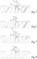
- the axial rake angle on a point of the cutting edge is measured in a plane that is parallel with the longitudinal axis and that comprises a tangent to a circle cut by the point when the tool is rotated without feed, c.f. the views of Figs. 5-8 .
- the axial rake angle ⁇ is positive, and equal or less than the helix angle at the front end of the chip flute which is rotationally in front thereof.
- the axial rake angle ⁇ is 5° less than the helix angle and thus 43°.
- the transition cutting edge 11 is continuously curved, c.f. Figs. 3 and 4 .
- Each front cutting edge 10 comprises a central portion 16 extending radially outward from the central region at the longitudinal axis 4, and a peripheral portion 17 extending radially outward from an inner end at the central portion 16 to an outer end at the transition cutting edge 11, c.f. Fig. 4 .
- the axial rake angle ⁇ of the central portion 16 of the front cutting edge 10 is constant and in the shown embodiment 10°.
- the axial rake angle ⁇ transitions form the axial rake angle ⁇ of the transition cutting edge 11 at the outer end to the axial rake angle ⁇ of the central portion 16 of the front cutting edge 10 at the inner end.
- the rake angle ⁇ transitions radially inward along the peripheral cutting edge 17 from 43° to 10°.
- the transition of the rake angle ⁇ along the peripheral portion 16 of the front cutting edge 10 is continuous.
- the cutting head further comprises a web 18, wherein as seen in a front end view, the inner end of the peripheral portion 17 of the front cutting edge 10 is located at the intersection 19 of the chip flute 13 and the web 18.
- the inner end of the peripheral portion 17 is located a radial distance of 30% of the cutting diameter of the cutting circle 12 from the longitudinal axis 4. In the shown embodiment, this radial distance from the central longitudinal axis 4 to the inner end of the peripheral portion is 3mm.
- the location of the inner end of the peripheral portion 17 is also to the location of the outer end of the central portion 16 of the front cutting edge 10.
- the outer end of the peripheral portion 17 is located a radial distance of 42,5% of the cutting diameter of the cutting circle 12 from the longitudinal axis 4.. In the shown embodiment, this radial distance from the central longitudinal axis 4 to the outer end of the peripheral portion is 4,25 mm. The location of the outer end of the peripheral portion 17 is also to the location of the inner end of the transition cutting edge 11.
- the radial length of the transition cutting edge 11 is equal for all four front cutting edges 10. Also, the radial length of the peripheral portion 17 of the front cutting edge 10 is equal for all four front cutting edges 10. Two of the front cutting edges 10 have a shorter central portion 16 than the other two.
- the cutting head 2 which as part of the square end mill tool, is rotatable around the longitudinal axis 4 in a direction of rotation 6, which is the direction of rotation when the square end mill tool is operated for normal cutting operation.
- the square end mill tool is operated for milling a surface at least partly limited by an approximately 90° thereto extending wall.
- the square end mill tool is rotated in the direction of rotation while being fed in a radial direction, and optionally in addition, in the axially forward direction.
- the square end mill tool is of a type wherein the cutting head 2 is a one-piece integral unit with a shaft 19, which is connectable to a spindle of a CNC machine.
Landscapes
- Engineering & Computer Science (AREA)
- Mechanical Engineering (AREA)
- Milling Processes (AREA)
Abstract
The present invention relates to an end mill tool for metal cutting comprising a cutting head (2), which is rotatable around a longitudinal axis (4) in a direction of rotation (6). The cutting head (2) comprises a plurality of cutting teeth (7), which each has a cutting edge formed at an intersection of a respective rake surface (8) and a respective clearance surface (9), and a plurality of chip flutes (13), which, rotationally in front of a respective one of the plurality of cutting teeth (7), each extends axially rearward from the front end (3), and which each has a respective helix angle α. The cutting edge of each of the plurality of cutting teeth (7) comprises at the front end (3), a front cutting edge (10) extending radially outward from a central region at the longitudinal axis (4) and a transition cutting edge (11) extending from the front cutting edge (10) to a side cutting edge (14). The clearance surface (9) of each of the cutting teeth (7) along the transition cutting edge (11), in a direction of the extension of the transition cutting edge (11), is convex. The rake surface (8) of each of the plurality of cutting teeth (7) has an axial rake angle β. Along the transition cutting edge (11), the axial rake angle β is positive, and equal or less than the helix angle α at the front end of the chip flute (13) which is rotationally in front thereof.
Description
- The present invention relates to a an end mill tool for metal cutting.
- A wide range of components are machined from many different types of material, such as metal, composites or combinations thereof. Accordingly, a variety of different cutting tools, and in particular milling tools such as end mills, have been developed. Conventionally, an end mill comprises a plurality of cutting edges, which extend axially along the tool and radially along a front end of the tool. The teeth have front cutting edges that cut a surface in an axial forward feed direction, and side cutting edges that cut a surface in a radial feed direction. A front cutting edge, typically extends radially outward from a center of the tool toward a corner portion. The corner portion of the cutting edge connects the front cutting edge with the side cutting edge.
- A problem with such known end mills is that the corner portion is prone to wear and damage such as notch wear and chipping.
- It is an object of the present invention to at least partly obviate the above mentioned problems. This object is achieved according to the invention by means of an end mill according to
claim 1. - The present invention relates to an end mill tool for metal cutting comprising a body with a cutting head, which cutting head has a front end and a central longitudinal axis extending rearward from the front end, wherein the end mill tool is rotatable around the longitudinal axis in a direction of rotation, and wherein the cutting head comprises
- a plurality of cutting teeth, which each has a cutting edge formed at an intersection of a respective rake surface and a respective clearance surface, and
- a plurality of chip flutes, which, rotationally in front of a respective one of the plurality of cutting teeth, each extends axially rearward from the front end, and which each has a respective helix angle,
wherein the cutting edge of each of the plurality of cutting teeth comprises - at the front end, a front cutting edge extending radially outward from a central region at the longitudinal axis,
- a side cutting edge extending axially rearward from a radially outer region of the front end, and
- a transition cutting edge extending from the front cutting edge to the
side cutting edge,
wherein - the clearance surface of each of the cutting teeth along the transition cutting edge, in a direction of the extension of the transition cutting edge, is convex, and
- the rake surface of each of the plurality of cutting teeth has an axial
rake angle, - positive, and
- equal or less than the helix angle at the front end of the chip flute which is rotationally in front thereof.
- End mill tools, or in other words end milling tools, that have both an axially forward cutting front edge and a radially cutting side edge are usually provided with a chamfer at the transition of the front edge to side edge. The chamfer removes a sharp corner at the transition. Thereby, in prior art end mills, a new sharp corner is created on the front cutting edge at a small distance radially inward from the periphery. In the present end mill tool according to invention, thanks to the cutting edge, along the chamfer, having a rake surface with an axial rake angle that is less of equal to the helix angle of the front end of the chip flute at the transition, any new sharp corner due to the convex clearance surface is avoided. Thereby a transition cutting edge with a positive axial rake angle is made stronger to better withstand wear and chipping.
- The present invention relates to an end mill tool for metal cutting. The end mill tool comprises a body with a cutting head. Optionally, the end mill tool is of a type wherein the cutting head is a one-piece integral unit with a shaft, sometimes called "solid round tools". Alternatively, the end mill tool is a exchangeable head and is connectable to a shaft. The shaft optionally has a coupling at the rear end. Thereby the cutting head is connectable to a machine spindle or to an adapter for a machine spindle. The machine spindle typically is part of a machine, for example a CNC machine. Preferably, the end mill tool comprises a wear resistant material such as for example coated or non-coated cemented carbide, cermet, ceramic or CBN.
- The cutting head has a front end and a central longitudinal axis extending rearward from the front end, wherein the end mill is rotatable around the longitudinal axis in a direction of rotation. The cutting head defines a cutting circle with a cutting diameter. The cutting circle is to be understood as the circle formed by the radially most outer point of any of the cutting edges when the endmill is rotated one turn around the longitudinal axis without feeding the tool in any direction. The direction of rotation is the direction that the end mill tool is rotated during normal cutting operation.
- According to an embodiment, the cutting head is elongated in the longitudinal direction. Optionally, the axial length of the cutting head is equal or smaller, preferably larger, than the diameter of the cutting circle.
- The cutting head comprises a plurality of cutting teeth, which each has a cutting edge formed at an intersection of a respective rake surface and a respective clearance surface. For example, the cutting head comprises at least 2, preferably at least 4 cutting teeth. For example, the cutting head comprises at most 10, preferably at most 6 cutting teeth.
- The cutting teeth are provided in the front end of the cutting head, which each extend radially outward from a central region at the longitudinal axis and each present a mainly axially forward cutting front cutting edge. Therein, optionally the front cutting edge of a specific cutting tooth extends from the longitudinal axis or a from a point a distance radially outward therefrom. Optionally, as seen in a front end view, the front cutting edge of a specific cutting tooth extends mainly along a radius or along a chord, wherein the cutting edge optionally is straight or curved. Optionally all front cutting edges extend from the same radial distance from the longitudinal axis, or, from different radial distances. For example, a number of the cutting edges start at a first, same radial distance and a number start at a second, same radial distance, which is different from the first radial distance. The front end of the cutting head preferably is an axially forwardly facing end surface of the end mill tool.
- The cutting teeth continue axially rearward from a radially outer region of the front end and each present a mainly radially cutting side cutting edge. Preferably, the side cutting edges cut radially only. The teeth typically extend along a peripheral surface of the body of the cutting head. The side cutting edge of each of the cutting teeth extends with an angle to the longitudinal axis and preferably form a helix. The axial extension of the side cutting edge rearward from the front end is for example less than, equal to or longer than the cutting diameter, and preferably 1 - 5 times the cutting diameter. According to a preferred embodiment, the side cutting edges are continuous. Alternatively, the side cutting edges are interrupted by grooves. In applications, grooves are beneficial for reducing the breadth of cut chips, or for creating additional minor cutting edges.
- The cutting head comprises a plurality of chip flutes, which, rotationally in front of a respective one of the plurality of cutting teeth, each extends axially rearward from the front end. The chip flutes typically extend along the peripheral surface of the body of the cutting head.
- Each chip flute extends with an angle to the longitudinal axis and preferably forms a helix. The angle is denominated "helix angle" also for chip flutes that are angled without forming a helix and is to be understood as the angle between a bottom of the chip flute and the longitudinal axis. Preferably, the helix angle of a specific side cutting edge is equal to helix angle of the chip flute that is rotationally in front thereof. Optionally the helix angle of the chip flutes varies or is constant, for example, the helix angle decreases or increases axially rearward from the front end. According to an embodiment, the helix angle at the front end of the chip flute, which is rotationally in front of the transition cutting edge, is at least 10° and at most 60°, preferably, at least 20° and at most 50°. Within this range, the chip flutes provide satisfactory chip evacuation and/or chip breaking for most applications.
- Each cutting edge of the plurality of teeth further comprises a transition cutting edge extending from the front cutting edge to the side cutting edge. Preferably, the transition cutting edge has a radially inner end at the front end connecting to the front cutting edge and an axially rear end connecting to the side cutting edge at an axial front end of the side cutting edge.
- For example, the transition cutting edge extends over the radially outer corner where the peripheral side surface meets the front end surface of the cutting head body. Each chip flute has a front end, which is a portion of the chip flute that is located at the corner portion with the transition cutting edge.
- The transition cutting edge extends at least partly along a chamfer in form of a clearance surface. The clearance surface of the translon cutting edge is convex in a direction of the extension of the transition cutting edge, i.e. in a radial direction along the front end. The convex curvature of the clearance surface can be seen in a plane that is normal to a tangent of a circle cut by a point on the transition cutting edge when the tool is rotated without feed. Preferably, as seen in the rotational direction behind the point on the transition cutting edge, i.e. along a portion of the circle cut by the point when the tool is rotated without feed, the clearance surface extends at a constant clearance angle.
- Each rake surface of the cutting edges has an axial rake angle. The axial rake angle is to be understood as the inclination of the rake surface relative the longitudinal axis. The axial rake angle on a point of the cutting edge may be measured in a plane that is parallel with the longitudinal axis and that comprises a tangent to a circle cut by the point when the tool is rotated without feed.
- Preferably, the axial rake angle along the side cutting edge is 0°.
- Along the transition cutting edge, the axial rake angle is positive, and equal or less than the helix angle at the front end of the chip flute which is rotationally in front thereof. The axial rake angle is considered positive when the rake surface is inclined rotationally rearward in a direction axially rearward. According to an embodiment, along the transition cutting edge, the axial rake angle is maximally 10° less than the helix angle. Thereby it is ensured that the transition cutting edge is sufficiently smooth for most applications. For example, any corners are obtuse with having an angle of at least 170°. Preferably, the axial rake angle is chosen such that the transition cutting edge is continuously curved.
- According to preferred embodiments, the front cutting edge comprises a central portion extending radially outward from the central region at the longitudinal axis, and a peripheral portion, extending radially outward from an inner end at the central portion to an outer end at the transition cutting edge.
- Over the length of the peripheral portion, the axial rake angle transitions form the axial rake angle of the transition cutting edge at the outer end to the axial rake angle of the central portion at the inner end. Thereby the front cutting edge can be given any desired axial rake angle at the central portion without introducing sharp corners. Preferably, along the transition cutting edge (11), the axial rake angle β is constant. Thereby grinding of the axial rake angle is easier. Preferably, the transition of the axial rake angle of the peripheral portion is continuous. Thereby, the transition cutting edge and the peripheral portion of the front cutting edge are continuous, for example continuously curved or straight.
- According to an embodiment, the axial rake angle of the central portion of the front cutting edge is constant. Thereby the grinding of the rake surface is easier. Preferably, the axial rake angle of the central portion of the front cutting edge is positive. For example, the axial rake angle is at least 5° and at most 30°. Large, positive rake angles provide a more pointed cutting edge which lowers cutting forces and heat generation. Smaller positive rake angles provide a blunter cutting edge, which is stronger an advantageous when cutting harder materials.
- Preferably, the cutting head further comprises a web, wherein as seen in a front end view, the inner end of the peripheral portion of the front cutting edge is located at the intersection of the chip flute and the web. When grinding the rake surface in embodiments wherein the axial rake angle transitions along the peripheral portion of the front cutting edge, the grinding wheel is progressively tilted along the peripheral cutting edge. If the peripheral portion of the front cutting edge is outside of the web, such progressive tilting is easier as compared to griding inside the web. The space cut by the grinding wheel in the web is sometimes referred to as "gash".
- According to an embodiment, as seen in a front end view, the inner end of the peripheral portion is located a radial distance of at least 25% and at most 30% of the cutting diameter from the cutting circle. It is easier to grind the changing rake surface at a distance from the center. The location of the inner end of the peripheral portion is also to the location of the outer end of the central portion of the front cutting edge.
- According to an embodiment, as seen in a front end view, the outer end of the peripheral portion is located a radial distance of at least 37.5% and at most 42,5% of the cutting diameter from the longitudinal axis. Thereby it is ensured that the transition cutting edge with the constant axial rake angel according to the invention is sufficiently long to ensure a smooth transition and front cutting edge. The location of the outer end of the peripheral portion is also to the location of the inner end of the transition cutting edge.
- According to embodiments, the end mill tool is square end mill tool, a chamfer end mill tool, a tapered end mill tool or a corner end mill tool. For example, a front end of the side cutting edge is located a distance of at most 5% of the cutting diameter axially rearward of a most forward front point of the cutting head. Optionally, the most forward point is a radially outer point of a cutting edge or a tool tip at the central longitudinal axis. The most forward point may also be any point on a front cutting edge without axial extension. For example, a corner radius of the transition cutting edge is less than 25% diameter of the cutting circle. The inventive axial rake angle of the transition cutting edge is especially advantageous for such tools. Due to a relative axially short corner portion of such tools, the transition edges with a small radius of curvature tend to be more prone to wear and chipping, especially at sharp corners introduced in the front cutting edge when gridding the chamfer/clearance surface.
- The front cutting edges may in embodiments have an inclination relative the longitudinal axis so that they cut a short axial distance in addition to their mainly axially forward cutting direction. Optionally, two or more of the cutting edges meet in the axially most forward point forming a tip.
- In the following, example embodiments will be described in greater detail and with reference to the accompanying drawings, in which:
-
Fig. 1 is a perspective view of an embodiment of an end mill tool for metal cutting according to the invention; -
Fig. 2 is a side view of the embodiment of the subject end mill; -
Fig. 3 is an enlarged view of a forward end of the end mill tool sown inFig. 2 ; -
Fig. 4 is a front end view of the embodiment of the subject end mill; -
Fig. 5 - 8 are cross sections over a front cutting edge as indicated inFig. 4 showing an axial rake angle. - All the figures are schematic, not necessarily to scale, and generally only show parts which are necessary in order to elucidate the respective embodiments, whereas other parts may be omitted or merely suggested. Unless otherwise indicated, like reference numerals refer to like parts in different figures.
- With reference to
Figs. 1 - 8 , an embodiment of the end mill in form of a square end mill tool is shown. The square end mill tool comprises abody 1, with a cuttinghead 2. The cuttinghead 2 has afront end 3, which is also the front end of the square end mill tool, and a centrallongitudinal axis 4 extending rearward from thefront end 3. Thefront end 3 of the cuttinghead 2 is an axially forwardly facing end surface of the square end mill tool. - The
axis 4 is the central longitudinal axis of the square end mill tool. The square end mill tool has arear end 5 at the axially opposite end to thefront end 3. - The cutting head comprises a plurality of cutting
teeth 7, which each has a cutting edge formed at an intersection of arespective rake surface 8 and arespective clearance surface 9. The square end mill tool according to the embodiment comprises four cuttingteeth 7. - The cutting edges each has radially most outer point at the same radial distance from the
longitudinal axis 4. The cuttinghead 2 defines a cuttingcircle 12 formed by radially most outer points of the cutting edges when the square end mill tool is rotated one turn around thelongitudinal axis 4 without being fed in any direction. The cuttingcircle 12 has a cutting diameter, which in the shown embodiment is 10 mm. - Each
tooth 7 presents a mainly axially forward cuttingfront cutting edge 10, wherein eachfront cutting edge 10 extends radially outward from a central region at thelongitudinal axis 4. Two of the front the cutting edges 10 start at a same, first radial distance close tolongitudinal axis 4, and the other two of the four front cutting edges 10 start at a same, second radial distance from thelongitudinal axis 4, wherein the second radial distance is larger than the first radial distance. Each of the four front cutting edges 10 extend at the side of thelongitudinal axis 4 generally along a chord of the cuttingcircle 12. Eachfront cutting edge 10 is straight both when viewed in a front end vies and in a side view, c.f.Fig. 4 and3 , respectively. - Each
tooth 7 continues axially rearward from a radially outer region of thefront end 2 and presents a mainly only radially cuttingside cutting edge 14, which extend axially rearward from thefront end 3 along a peripheral surface of the body of the cuttinghead 2. Theside cutting edge 14 of each of the cuttingteeth 7 extends with an angle to the longitudinal axis and forms a helix. - The cutting
head 2 comprises a plurality of chip flutes 13, which extend axially rearward from thefront end 3 along a peripheral surface of the body of the cuttinghead 2. Eachchip flute 13 extends rotationally in front of a respective one of the plurality of cuttingteeth 7. - Each
chip flute 13 forms a helix and extends with an angle in form of a helix angle α to thelongitudinal axis 4. The helix angle α is measured as the angle between a bottom of thechip flute 13 and the longitudinal axis, c.f.Fig. 3 . The helix angle of aside cutting edge 14 is equal to helix angle α of the chip flute that is rotationally in front thereof. - Each cutting edge of the plurality of
teeth 7 further comprises atransition cutting edge 11, which extends over the radially outer corner where the peripheral side surface meets the front end surface of the cuttinghead 2, c.f.Fig. 4 . Specifically, thetransition cutting edge 11 has a radially inner end connecting to thefront cutting edge 10 and an axially rear end connecting to theside cutting edge 14. - Each
chip flute 13 has a front end, which is a portion of the chip flute that is located at the corner portion with the transition cutting edge. In the shown embodiment, the helix angle α is the same for all chip flutes 13, and also constant along the axial length including the front end. The helix angle α is 48°. - The
transition cutting edge 11 extends at least partly along achamfer 15 in form of aclearance surface 9. Theclearance surface 15 of thetranslon cutting edge 11 is convex in a direction of the extension of thetransition cutting edge 11, c.f.Fig. 3 . - Each
rake surface 8 of the cutting edges 10 has an axial rake angle β. The axial rake angle β is to be understood as the inclination of therake surface 8 relative the longitudinal axis. The axial rake angle on a point of the cutting edge is measured in a plane that is parallel with the longitudinal axis and that comprises a tangent to a circle cut by the point when the tool is rotated without feed, c.f. the views ofFigs. 5-8 . - As can be seen in
Fig. 5 , along thetransition cutting edge 11, the axial rake angle β is positive, and equal or less than the helix angle at the front end of the chip flute which is rotationally in front thereof. Specifically, in the shown embodiment, the axial rake angle β is 5° less than the helix angle and thus 43°. Preferably, thetransition cutting edge 11 is continuously curved, c.f.Figs. 3 and4 . - Each
front cutting edge 10 comprises acentral portion 16 extending radially outward from the central region at thelongitudinal axis 4, and aperipheral portion 17 extending radially outward from an inner end at thecentral portion 16 to an outer end at thetransition cutting edge 11, c.f.Fig. 4 . - As can be seen in
Fig. 8 , the axial rake angle β of thecentral portion 16 of thefront cutting edge 10 is constant and in the shownembodiment 10°. - As can be seen in
Figs. 6 and 7 , over the length of theperipheral portion 17, the axial rake angle β transitions form the axial rake angle β of thetransition cutting edge 11 at the outer end to the axial rake angle β of thecentral portion 16 of thefront cutting edge 10 at the inner end. Thus, in the shown embodiment, the rake angle β transitions radially inward along theperipheral cutting edge 17 from 43° to 10°. The transition of the rake angle β along theperipheral portion 16 of thefront cutting edge 10 is continuous. - The cutting head further comprises a
web 18, wherein as seen in a front end view, the inner end of theperipheral portion 17 of thefront cutting edge 10 is located at theintersection 19 of thechip flute 13 and theweb 18. The inner end of theperipheral portion 17 is located a radial distance of 30% of the cutting diameter of the cuttingcircle 12 from thelongitudinal axis 4. In the shown embodiment, this radial distance from the centrallongitudinal axis 4 to the inner end of the peripheral portion is 3mm. The location of the inner end of theperipheral portion 17 is also to the location of the outer end of thecentral portion 16 of thefront cutting edge 10. - The outer end of the
peripheral portion 17 is located a radial distance of 42,5% of the cutting diameter of the cuttingcircle 12 from thelongitudinal axis 4.. In the shown embodiment, this radial distance from the centrallongitudinal axis 4 to the outer end of the peripheral portion is 4,25 mm. The location of the outer end of theperipheral portion 17 is also to the location of the inner end of thetransition cutting edge 11. - The radial length of the
transition cutting edge 11 is equal for all four front cutting edges 10. Also, the radial length of theperipheral portion 17 of thefront cutting edge 10 is equal for all four front cutting edges 10. Two of the front cutting edges 10 have a shortercentral portion 16 than the other two. - The cutting
head 2, which as part of the square end mill tool, is rotatable around thelongitudinal axis 4 in a direction ofrotation 6, which is the direction of rotation when the square end mill tool is operated for normal cutting operation. Typically, the square end mill tool is operated for milling a surface at least partly limited by an approximately 90° thereto extending wall. During operation, the square end mill tool is rotated in the direction of rotation while being fed in a radial direction, and optionally in addition, in the axially forward direction. - The cutting head has an elongated extension along the
longitudinal axis 4 and extends rearward from the front end is approximately 2 times the cutting diameter of the cuttingcircle 12. The rear end of the cutting head is the rear end of the side cutting edges 14. A front end of theside cutting edge 14 is located a distance of 3% of the cutting diameter axially rearward of a forwardmost front point of the cuttinghead 2. In the shown embodiment the axial distance from the most forward tip to the front end of theside cutting edge 14 is 0,3 mm. The forward most front point in the shown embodiment is any position on a front cutting edges 10. - The square end mill tool is of a type wherein the cutting
head 2 is a one-piece integral unit with ashaft 19, which is connectable to a spindle of a CNC machine.
along the transition cutting edge, the axial rake angle is
Claims (15)
- An end mill tool for metal cutting comprising a body (1) with a cutting head (2), which cutting head (2) has a front end (3) and a central longitudinal axis (4) extending rearward from the front end (3), wherein the end mill tool is rotatable around the longitudinal axis (4) in a direction of rotation (6), and wherein the cutting head (2) comprises- a plurality of cutting teeth (7), which each has a cutting edge formed at an intersection of a respective rake surface (8) and a respective clearance surface (9), and- a plurality of chip flutes (13), which, rotationally in front of a respective one of the plurality of cutting teeth (7), each extends axially rearward from the front end (3), and which each has a respective helix angle α,wherein the cutting edge of each of the plurality of cutting teeth (7) comprises- at the front end (3), a front cutting edge (10) extending radially outward from a central region at the longitudinal axis (4),- a side cutting edge (14) extending axially rearward from a radially outer region of the front end (3), and- a transition cutting edge (11) extending from the front cutting edge (10) to the side cutting edge (14),wherein- the clearance surface (9) of each of the cutting teeth (7) along the transition cutting edge (11), in a direction of the extension of the transition cutting edge (11), is convex, and- the rake surface (8) of each of the plurality of cutting teeth (7) has an axial rake angle β,characterized in that
along the transition cutting edge (11), the axial rake angle β is- positive, and- equal or less than the helix angle α at the front end of the chip flute (13) which is rotationally in front thereof. - The end mill tool as claimed in claim 1, wherein, along the transition cutting edge (11), the axial rake angle β is maximally 10° less than the helix angle α.
- The end mill tool as claimed in claim 1 or 2, wherein, along the transition cutting edge (11), the axial rake angle β is constant.
- The end mill tool as claimed in any preceding claim, wherein the transition cutting edge (11) is continuously curved.
- The end mill tool as claimed in any preceding claim, wherein the helix angle α at the front end of the chip flute (13) which is rotationally in front of the transition cutting edge (11) is at least 10° and at most 60°.
- The end mill tool as claimed in any preceding claim, wherein- the front cutting edge (10) comprises a central portion (16) extending radially outward from the central region at the longitudinal axis (4), and a peripheral portion (17), extending radially outward from an inner end at the central portion (16) to an outer end at the transition cutting edge (11), and- the cutting head (2) defines a cutting circle (12) with a cutting diameter.
- The end mill tool as claimed in claim 6, wherein, over the length of the peripheral portion (17), the axial rake angle β transitions form the axial rake angle β of the transition cutting edge (11) at the outer end to the axial rake angle β of the central portion (16) at the inner end.
- The end mill tool as claimed in claim 6 or 7, wherein the transition of the axial rake angle β of the peripheral (17) portion is continuous.
- The end mill tool claimed in any claim 6 - 8, wherein the axial rake angle β of the central portion (16) is constant.
- The end mill tool as claimed in claim 9, wherein the axial rake angle β of the central portion (16) is positive, and at least 5° and at most 30°.
- The end mill tool claimed in any claim 6- 10, wherein the cutting head (2) further comprises a web (18), wherein as seen in a front end view, the inner end of the peripheral portion (17) is located at the intersection of the chip flute (13) and the web (18).
- The end mill tool claimed in any claim 6 - 11, wherein, as seen in a front end view, the inner end of the peripheral portion (17) is located a radial distance of at least 25% and at most 30% of the cutting diameter of the cutting circle from the longitudinal axis (4).
- The end mill tool claimed in any claim 6 - 12, wherein, as seen in a front end view, the outer end of the peripheral portion (17) is located a radial distance of at least 37,5% and at most 42,5% of the cutting diameter from the longitudinal axis (4).
- The end mill tool claimed in any preceding claim, wherein the end mill tool is a square end mill.
- The end mill tool claimed in any claim 6 - 14, wherein a front end of the side cutting edge (14) is located a distance of at most 5% of the cutting diameter axially rearward of a forwardmost front tip of the cutting head (2).
Priority Applications (3)
| Application Number | Priority Date | Filing Date | Title |
|---|---|---|---|
| EP23186588.2A EP4494792A1 (en) | 2023-07-20 | 2023-07-20 | End mill tool |
| CN202480032261.3A CN121175138A (en) | 2023-07-20 | 2024-05-23 | Vertical milling cutter |
| PCT/EP2024/064154 WO2025016593A1 (en) | 2023-07-20 | 2024-05-23 | End mill tool |
Applications Claiming Priority (1)
| Application Number | Priority Date | Filing Date | Title |
|---|---|---|---|
| EP23186588.2A EP4494792A1 (en) | 2023-07-20 | 2023-07-20 | End mill tool |
Publications (1)
| Publication Number | Publication Date |
|---|---|
| EP4494792A1 true EP4494792A1 (en) | 2025-01-22 |
Family
ID=87426545
Family Applications (1)
| Application Number | Title | Priority Date | Filing Date |
|---|---|---|---|
| EP23186588.2A Pending EP4494792A1 (en) | 2023-07-20 | 2023-07-20 | End mill tool |
Country Status (3)
| Country | Link |
|---|---|
| EP (1) | EP4494792A1 (en) |
| CN (1) | CN121175138A (en) |
| WO (1) | WO2025016593A1 (en) |
Citations (3)
| Publication number | Priority date | Publication date | Assignee | Title |
|---|---|---|---|---|
| JPS59175915A (en) * | 1983-03-24 | 1984-10-05 | Kawasaki Heavy Ind Ltd | End mill |
| US20030180104A1 (en) * | 2002-03-25 | 2003-09-25 | Hitachi Tool Engineering Ltd. | Radius end mill having radius edge enhanced in resistance to chipping and fracture |
| US20080286056A1 (en) * | 2002-12-26 | 2008-11-20 | Mitsubishi Materials Corporation | Radius end mill |
-
2023
- 2023-07-20 EP EP23186588.2A patent/EP4494792A1/en active Pending
-
2024
- 2024-05-23 CN CN202480032261.3A patent/CN121175138A/en active Pending
- 2024-05-23 WO PCT/EP2024/064154 patent/WO2025016593A1/en active Pending
Patent Citations (3)
| Publication number | Priority date | Publication date | Assignee | Title |
|---|---|---|---|---|
| JPS59175915A (en) * | 1983-03-24 | 1984-10-05 | Kawasaki Heavy Ind Ltd | End mill |
| US20030180104A1 (en) * | 2002-03-25 | 2003-09-25 | Hitachi Tool Engineering Ltd. | Radius end mill having radius edge enhanced in resistance to chipping and fracture |
| US20080286056A1 (en) * | 2002-12-26 | 2008-11-20 | Mitsubishi Materials Corporation | Radius end mill |
Also Published As
| Publication number | Publication date |
|---|---|
| WO2025016593A1 (en) | 2025-01-23 |
| CN121175138A (en) | 2025-12-19 |
Similar Documents
| Publication | Publication Date | Title |
|---|---|---|
| EP3411174B1 (en) | Tool with right-hand and left-hand cutting features extending along the full length of the cutting zone | |
| EP0569451B1 (en) | Indexable insert drill and an insert with a symmetrical drill point and cutting edges of different lengths | |
| CN101247914B (en) | Arc head end mill and cutting method | |
| EP2650069B1 (en) | Cutting head with coolant channel and method of forming such a cutting head | |
| US20200108449A1 (en) | Cutting head having tip portion with radially extending front cutting edges provided with both negative and positive rake angles, and rotary cutting tool | |
| EP1807233A1 (en) | Helical flute end mill with multi-section cutting edge | |
| CN101557899A (en) | Rotary cutting tool | |
| US20250050434A1 (en) | End mill | |
| EP4494792A1 (en) | End mill tool | |
| CN210702770U (en) | Milling cutter with end chip grooves | |
| JP7727830B2 (en) | Drill and cutting process | |
| US11951553B2 (en) | Rotatable cutting head having tip portion with three radially extending cutting edges forming a rectilinear rotational profile | |
| US12109635B2 (en) | Rotatable cutting head having tip portion with radially extending cutting edges forming a cutting profile having concave and convex sub-portions | |
| KR20260036171A (en) | End mill tool | |
| US20030053870A1 (en) | Arc-ended cutting tools | |
| EP3981529A1 (en) | Drill point | |
| EP4509251A1 (en) | Milling tool | |
| JP6902284B2 (en) | Cutting tools | |
| EP3556496B1 (en) | A drilling tool | |
| CN216966540U (en) | Finish machining milling cutter for machining threads | |
| JP7706561B2 (en) | Rotary tool and method for manufacturing machined product | |
| US20240390991A1 (en) | Cutting Head Having Two Pairs of Cutting Arms with Unequal Cutting Diameters, and Rotary Cutting Tool | |
| CN217571034U (en) | Round nose milling cutter for processing low-sulfur stainless steel | |
| JPH06218614A (en) | End mill | |
| WO2025105312A1 (en) | Drill |
Legal Events
| Date | Code | Title | Description |
|---|---|---|---|
| PUAI | Public reference made under article 153(3) epc to a published international application that has entered the european phase |
Free format text: ORIGINAL CODE: 0009012 |
|
| STAA | Information on the status of an ep patent application or granted ep patent |
Free format text: STATUS: THE APPLICATION HAS BEEN PUBLISHED |
|
| AK | Designated contracting states |
Kind code of ref document: A1 Designated state(s): AL AT BE BG CH CY CZ DE DK EE ES FI FR GB GR HR HU IE IS IT LI LT LU LV MC ME MK MT NL NO PL PT RO RS SE SI SK SM TR |
|
| STAA | Information on the status of an ep patent application or granted ep patent |
Free format text: STATUS: REQUEST FOR EXAMINATION WAS MADE |
|
| 17P | Request for examination filed |
Effective date: 20250722 |