EP4494785A1 - Induction heating of a component during direct energy deposition repair - Google Patents
Induction heating of a component during direct energy deposition repair Download PDFInfo
- Publication number
- EP4494785A1 EP4494785A1 EP24186457.8A EP24186457A EP4494785A1 EP 4494785 A1 EP4494785 A1 EP 4494785A1 EP 24186457 A EP24186457 A EP 24186457A EP 4494785 A1 EP4494785 A1 EP 4494785A1
- Authority
- EP
- European Patent Office
- Prior art keywords
- component
- induction coil
- various embodiments
- controller
- electrical current
- Prior art date
- Legal status (The legal status is an assumption and is not a legal conclusion. Google has not performed a legal analysis and makes no representation as to the accuracy of the status listed.)
- Pending
Links
Images

Classifications
-
- H—ELECTRICITY
- H05—ELECTRIC TECHNIQUES NOT OTHERWISE PROVIDED FOR
- H05B—ELECTRIC HEATING; ELECTRIC LIGHT SOURCES NOT OTHERWISE PROVIDED FOR; CIRCUIT ARRANGEMENTS FOR ELECTRIC LIGHT SOURCES, IN GENERAL
- H05B6/00—Heating by electric, magnetic or electromagnetic fields
- H05B6/02—Induction heating
- H05B6/06—Control, e.g. of temperature, of power
-
- B—PERFORMING OPERATIONS; TRANSPORTING
- B22—CASTING; POWDER METALLURGY
- B22F—WORKING METALLIC POWDER; MANUFACTURE OF ARTICLES FROM METALLIC POWDER; MAKING METALLIC POWDER; APPARATUS OR DEVICES SPECIALLY ADAPTED FOR METALLIC POWDER
- B22F12/00—Apparatus or devices specially adapted for additive manufacturing; Auxiliary means for additive manufacturing; Combinations of additive manufacturing apparatus or devices with other processing apparatus or devices
- B22F12/90—Means for process control, e.g. cameras or sensors
-
- B—PERFORMING OPERATIONS; TRANSPORTING
- B22—CASTING; POWDER METALLURGY
- B22F—WORKING METALLIC POWDER; MANUFACTURE OF ARTICLES FROM METALLIC POWDER; MAKING METALLIC POWDER; APPARATUS OR DEVICES SPECIALLY ADAPTED FOR METALLIC POWDER
- B22F10/00—Additive manufacturing of workpieces or articles from metallic powder
- B22F10/20—Direct sintering or melting
- B22F10/25—Direct deposition of metal particles, e.g. direct metal deposition [DMD] or laser engineered net shaping [LENS]
-
- B—PERFORMING OPERATIONS; TRANSPORTING
- B22—CASTING; POWDER METALLURGY
- B22F—WORKING METALLIC POWDER; MANUFACTURE OF ARTICLES FROM METALLIC POWDER; MAKING METALLIC POWDER; APPARATUS OR DEVICES SPECIALLY ADAPTED FOR METALLIC POWDER
- B22F12/00—Apparatus or devices specially adapted for additive manufacturing; Auxiliary means for additive manufacturing; Combinations of additive manufacturing apparatus or devices with other processing apparatus or devices
- B22F12/10—Auxiliary heating means
-
- B—PERFORMING OPERATIONS; TRANSPORTING
- B22—CASTING; POWDER METALLURGY
- B22F—WORKING METALLIC POWDER; MANUFACTURE OF ARTICLES FROM METALLIC POWDER; MAKING METALLIC POWDER; APPARATUS OR DEVICES SPECIALLY ADAPTED FOR METALLIC POWDER
- B22F7/00—Manufacture of composite layers, workpieces, or articles, comprising metallic powder, by sintering the powder, with or without compacting wherein at least one part is obtained by sintering or compression
- B22F7/06—Manufacture of composite layers, workpieces, or articles, comprising metallic powder, by sintering the powder, with or without compacting wherein at least one part is obtained by sintering or compression of composite workpieces or articles from parts, e.g. to form tipped tools
- B22F7/062—Manufacture of composite layers, workpieces, or articles, comprising metallic powder, by sintering the powder, with or without compacting wherein at least one part is obtained by sintering or compression of composite workpieces or articles from parts, e.g. to form tipped tools involving the connection or repairing of preformed parts
-
- B—PERFORMING OPERATIONS; TRANSPORTING
- B23—MACHINE TOOLS; METAL-WORKING NOT OTHERWISE PROVIDED FOR
- B23K—SOLDERING OR UNSOLDERING; WELDING; CLADDING OR PLATING BY SOLDERING OR WELDING; CUTTING BY APPLYING HEAT LOCALLY, e.g. FLAME CUTTING; WORKING BY LASER BEAM
- B23K26/00—Working by laser beam, e.g. welding, cutting or boring
- B23K26/34—Laser welding for purposes other than joining
- B23K26/342—Build-up welding
-
- B—PERFORMING OPERATIONS; TRANSPORTING
- B23—MACHINE TOOLS; METAL-WORKING NOT OTHERWISE PROVIDED FOR
- B23K—SOLDERING OR UNSOLDERING; WELDING; CLADDING OR PLATING BY SOLDERING OR WELDING; CUTTING BY APPLYING HEAT LOCALLY, e.g. FLAME CUTTING; WORKING BY LASER BEAM
- B23K26/00—Working by laser beam, e.g. welding, cutting or boring
- B23K26/60—Preliminary treatment
-
- B—PERFORMING OPERATIONS; TRANSPORTING
- B33—ADDITIVE MANUFACTURING TECHNOLOGY
- B33Y—ADDITIVE MANUFACTURING, i.e. MANUFACTURING OF THREE-DIMENSIONAL [3D] OBJECTS BY ADDITIVE DEPOSITION, ADDITIVE AGGLOMERATION OR ADDITIVE LAYERING, e.g. BY 3D PRINTING, STEREOLITHOGRAPHY OR SELECTIVE LASER SINTERING
- B33Y10/00—Processes of additive manufacturing
-
- B—PERFORMING OPERATIONS; TRANSPORTING
- B33—ADDITIVE MANUFACTURING TECHNOLOGY
- B33Y—ADDITIVE MANUFACTURING, i.e. MANUFACTURING OF THREE-DIMENSIONAL [3D] OBJECTS BY ADDITIVE DEPOSITION, ADDITIVE AGGLOMERATION OR ADDITIVE LAYERING, e.g. BY 3D PRINTING, STEREOLITHOGRAPHY OR SELECTIVE LASER SINTERING
- B33Y30/00—Apparatus for additive manufacturing; Details thereof or accessories therefor
-
- B—PERFORMING OPERATIONS; TRANSPORTING
- B33—ADDITIVE MANUFACTURING TECHNOLOGY
- B33Y—ADDITIVE MANUFACTURING, i.e. MANUFACTURING OF THREE-DIMENSIONAL [3D] OBJECTS BY ADDITIVE DEPOSITION, ADDITIVE AGGLOMERATION OR ADDITIVE LAYERING, e.g. BY 3D PRINTING, STEREOLITHOGRAPHY OR SELECTIVE LASER SINTERING
- B33Y40/00—Auxiliary operations or equipment, e.g. for material handling
- B33Y40/10—Pre-treatment
-
- G—PHYSICS
- G05—CONTROLLING; REGULATING
- G05D—SYSTEMS FOR CONTROLLING OR REGULATING NON-ELECTRIC VARIABLES
- G05D23/00—Control of temperature
- G05D23/19—Control of temperature characterised by the use of electric means
- G05D23/1951—Control of temperature characterised by the use of electric means with control of the working time of a temperature controlling device
-
- H—ELECTRICITY
- H05—ELECTRIC TECHNIQUES NOT OTHERWISE PROVIDED FOR
- H05B—ELECTRIC HEATING; ELECTRIC LIGHT SOURCES NOT OTHERWISE PROVIDED FOR; CIRCUIT ARRANGEMENTS FOR ELECTRIC LIGHT SOURCES, IN GENERAL
- H05B6/00—Heating by electric, magnetic or electromagnetic fields
- H05B6/02—Induction heating
- H05B6/10—Induction heating apparatus, other than furnaces, for specific applications
- H05B6/101—Induction heating apparatus, other than furnaces, for specific applications for local heating of metal pieces
-
- H—ELECTRICITY
- H05—ELECTRIC TECHNIQUES NOT OTHERWISE PROVIDED FOR
- H05B—ELECTRIC HEATING; ELECTRIC LIGHT SOURCES NOT OTHERWISE PROVIDED FOR; CIRCUIT ARRANGEMENTS FOR ELECTRIC LIGHT SOURCES, IN GENERAL
- H05B6/00—Heating by electric, magnetic or electromagnetic fields
- H05B6/02—Induction heating
- H05B6/36—Coil arrangements
- H05B6/44—Coil arrangements having more than one coil or coil segment
-
- B—PERFORMING OPERATIONS; TRANSPORTING
- B22—CASTING; POWDER METALLURGY
- B22F—WORKING METALLIC POWDER; MANUFACTURE OF ARTICLES FROM METALLIC POWDER; MAKING METALLIC POWDER; APPARATUS OR DEVICES SPECIALLY ADAPTED FOR METALLIC POWDER
- B22F7/00—Manufacture of composite layers, workpieces, or articles, comprising metallic powder, by sintering the powder, with or without compacting wherein at least one part is obtained by sintering or compression
- B22F7/06—Manufacture of composite layers, workpieces, or articles, comprising metallic powder, by sintering the powder, with or without compacting wherein at least one part is obtained by sintering or compression of composite workpieces or articles from parts, e.g. to form tipped tools
- B22F7/062—Manufacture of composite layers, workpieces, or articles, comprising metallic powder, by sintering the powder, with or without compacting wherein at least one part is obtained by sintering or compression of composite workpieces or articles from parts, e.g. to form tipped tools involving the connection or repairing of preformed parts
- B22F2007/068—Manufacture of composite layers, workpieces, or articles, comprising metallic powder, by sintering the powder, with or without compacting wherein at least one part is obtained by sintering or compression of composite workpieces or articles from parts, e.g. to form tipped tools involving the connection or repairing of preformed parts repairing articles
-
- B—PERFORMING OPERATIONS; TRANSPORTING
- B22—CASTING; POWDER METALLURGY
- B22F—WORKING METALLIC POWDER; MANUFACTURE OF ARTICLES FROM METALLIC POWDER; MAKING METALLIC POWDER; APPARATUS OR DEVICES SPECIALLY ADAPTED FOR METALLIC POWDER
- B22F7/00—Manufacture of composite layers, workpieces, or articles, comprising metallic powder, by sintering the powder, with or without compacting wherein at least one part is obtained by sintering or compression
- B22F7/06—Manufacture of composite layers, workpieces, or articles, comprising metallic powder, by sintering the powder, with or without compacting wherein at least one part is obtained by sintering or compression of composite workpieces or articles from parts, e.g. to form tipped tools
- B22F7/08—Manufacture of composite layers, workpieces, or articles, comprising metallic powder, by sintering the powder, with or without compacting wherein at least one part is obtained by sintering or compression of composite workpieces or articles from parts, e.g. to form tipped tools with one or more parts not made from powder
Definitions
- the present disclosure relates generally to aerospace component repair and, more particularly, to induction heating of a component during direct energy deposition repair.
- Directed energy deposition which is an additive manufacturing process in which focused thermal energy is used to fuse materials by melting as they are being deposited, functions by guiding energy, which acts as a laser that focuses on a specific area where the metal powders or wire are heated up and deposited after melting. Accordingly, DED in relation to additive manufacturing technology utilizes powder or wire feedstocks. This DED is a process utilized for the repair of aerospace components.
- a method for repairing a component without further damaging the component is disclosed herein.
- a magnetic field is applied to the component via an induction coil thereby causing a temperature of the component to increase. Responsive to the component reaching a desired temperature, the component is repaired via a direct energy deposition process.
- the induction coil is powered via an electrical current and wherein the electrical current is at least one of a direct electrical current or an alternating electrical current.
- the induction coil is a single coil.
- the induction coil is a set of coils.
- the component is a high temperature capable metallic alloy component.
- an amount of the heat applied to the component is dependent on a type of metallic alloy of the high temperature capable metallic alloy component.
- the desired temperature is determined via a set of sensors monitoring a temperature of the component as the component is heated via the induction coil.
- the component is moved into and out the induction coil via a motor.
- the component is moved into and out an extruder of a direct energy deposition system via the motor.
- the movement of the component is at least one of a rotational movement or a translational movement. Also disclosed herein is a system.
- the system includes a direct energy deposition device; an induction coil; a controller; and a tangible, non-transitory memory configured to communicate with the controller, the tangible, non-transitory memory having instructions stored thereon that, in response to execution by the controller, cause the controller to perform operations comprising: commanding the induction coil to apply a magnetic field to a component thereby causing a temperature of the component to increase; and, responsive to the component reaching a desired temperature, commanding the direct energy deposition device to repair the component.
- the induction coil is powered via an electrical current and wherein the electrical current is at least one of a direct electrical current or an alternating electrical current.
- the induction coil is a single coil.
- the induction coil is a set of coils.
- the component is a high temperature capable metallic alloy component.
- an amount of the heat applied to the component is dependent on a type of metallic alloy of the high temperature capable metallic alloy component.
- the desired temperature is determined via a set of sensors monitoring a temperature of the component as the component is heated via the induction coil.
- the component is moved into and out the induction coil via a motor.
- the component is moved into and out an extruder of a direct energy deposition system via the motor.
- the movement of the component is at least one of a rotational movement or a translational movement.
- the present disclosure may include any one or more of the individual features disclosed above and/or below alone or in any combination thereof.
- directed energy deposition utilizes guiding energy, which acts as a laser that focuses on a specific area where metal powders or wire feedstocks are heated up and deposited after melting. That is, typically, a small, localized area of the surface of the substrate is melted by the laser and powder or push wire is fed into the melt pool.
- DED directed energy deposition
- certain high temperature capable metallic alloys used in aerospace that could be repaired using DED processing are known to crack during the DED processing. Accordingly, there is a need to control the processing temperature and environmental conditions during DED processing in order to prevent or reduce damage with certain high temperature capable metallic alloys during the DED processing.
- the heating is performed via induction heating.
- local heating of the component using a conforming induction heating coil enables processing for repair via DED.
- the heating of the substrate during DED processing allows metallic alloys with high temperature strength to be repaired with a reduced occurrence of presenting a defect, such as cracking.
- a geometry of the feature being processed will dictate the geometry of the induction coil.
- the geometry of the coil provides free rotation of an axisymmetric component during processing via DED. Referring now to FIG.
- the DED system 100 which may also be referred to as a DED device, includes a 3-axis positioning system 110, a nozzle 120, a computer numerical control (CNC) controlled table 150, a laser 130, and a controller 160.
- the nozzle 120 is co-axial with the laser 130 with the laser 130 in the center and powder delivery achieved via the nozzle 120 around the laser 130.
- the 3-axis positioning system 110 extends from a fixed end 112 to a moveable end 114.
- the nozzle 120 and laser 130 are coupled to the moveable end 114 and configured to move with the moveable end 114.
- the 3-axis positioning system 110 is in electrical or wireless communication with the controller 160, which is configured to control a position of the 3-axis positioning system 110 during DED processing.
- a component under repair 140 may be affixed to the CNC controlled table 150 and positioned under the nozzle 120 and laser 130 under the control of controller 160.
- the nozzle 120 and the laser 130 are disposed at the distal end of the 3-axis positioning system 110.
- the nozzle 120 may comprise an annulus 210.
- solid powder may be fed through the annulus 210 in the nozzle 120.
- melting of the powder occurs when the powder arrives at the melt pool on the substrate that is created by the laser 130.
- the powder may be introduced to the nozzle 120 from a hopper and is carried via a stream of gas to the melt pool.
- solid wire may be fed through the annulus 210 in the nozzle 120.
- melting of the wire occurs when the wire arrives at the melt pool on the substrate that is created by the laser 130.
- the wire may be introduced to the nozzle 120 via a reel and fed to the melt pool.
- feeding of the powder or the wire to the nozzle 120 is controlled by the controller 160 from FIG. 1 .
- the nozzle 120 described herein may be one of a plurality of nozzles with varying annulus diameters, so the nozzles of the DED system 100 from FIG. 2 may enable a higher deposition rate and/or an improved surface finish and feature resolution relative to typical additive manufacturing systems.
- the component may have a cross-sectional geometry, such as square or round, among others, and may have a lengthwise geometry, such as straight or curved, among others, along a length of the component 302.
- a cross-sectional geometry such as square or round
- a lengthwise geometry such as straight or curved, among others, along a length of the component 302.
- the component 302 is shown to have a square cross-sectional geometry and to have a curved lengthwise geometry along the length of the component 302.
- system 300 includes the DED system 100, an induction coil 304, a rotational motor 306, and a controller 160 that that is in communication with the DED system 100, the induction coil 304, and the rotational motor 306 and is configured to control the DED system 100, the induction coil 304, and the rotational motor 306.
- controller 160 may include one or more processors 308 configured to implement various logical operations in response to execution of instructions, for example, instructions stored on a non-transitory, tangible, computer-readable medium.
- the one or more processors can be a general-purpose processor, a microprocessor, a microcontroller, a digital signal processor (DSP), an application specific integrated circuit (ASIC), a field programmable gate array (FPGA) or other programmable logic device, discrete or transistor logic, discrete hardware components, or any combination thereof.
- Controller 160 may further include a memory 310 to store data, executable instructions, system program instructions, and/or controller instructions to implement the control logic of controller 160.
- Memory 310 may further store a database, a look up table, and/or other data objects for use by the executable instructions for implementing the control logic of controller 160.
- System program instructions and/or controller instructions may be loaded onto a non-transitory, tangible computer-readable medium having instructions stored thereon that, in response to execution by a controller, cause the controller to perform various operations.
- the term "non-transitory” is to be understood to remove only propagating transitory signals per se from the claim scope and does not relinquish rights to all standard computer-readable media that are not only propagating transitory signals per se.
- Controller 160 may further include an input 312.
- input 312 may be a bus or communication protocol with another device.
- input 312 may be a touch screen, keyboard, and/or other input device located on the DED system 100, the induction coil 304, and the rotational motor 306.
- input 312 may be a network connection for receiving inputs via a network connected device.
- Controller 160 is configured to communicate with and control the DED system 100, the induction coil 304, and the rotational motor 306. Controller 160 may send instructions to the DED system 100, the induction coil 304, and the rotational motor 306 to control the working parameters of the DED system 100, the induction coil 304, and the rotational motor 306.
- the instructions may be stored in memory 310 as a computer numerical control (CNC) program.
- the working parameters may include the RPM at which the component 302 is rotated, the direction in which the component 302 is rotated, the deposition speed of the material onto the component 302, and the electric current needed to heat the component 302 to a desired temperature.
- the working parameters may be received via input 312.
- the working parameters may be derived from input received via input 312. For example, input 312 may receive a type of metal of the component 302 and/or a thickness or diameter of the component 302, among other input information.
- controller 160 may use the input information to determine the working parameters to send to the DED system 100, the induction coil 304, and the rotational motor 306.
- controller 160 and, more specifically, memory 310, may store a database of working parameters for different material types, thicknesses, and diameters. For example, controller 160 may send a first set of working parameters to the DED system 100, the induction coil 304, and the rotational motor 306 in response to the input indicating that the component 302 is formed from a first metallic alloy having a first thickness.
- controller 160 may send a second set of working parameters, with at least one parameter being different, to the DED system 100, the induction coil 304, and the rotational motor 306 in response to the input indicating that the thickness of the component 302 is a second thickness that is different than the first thickness.
- controller 160 By adjusting the working parameters (e.g., RPM, direction, deposition speed, electric current, etc.) for different materials and sized materials, controller 160, the DED system 100, the induction coil 304, and the rotational motor 306 may deposit material having different thicknesses to repair the component 302. Adjusting the working parameters of the DED system 100, the induction coil 304, and the rotational motor 306 by the controller 160 allows for a uniform and consistent workpiece. The component 302 is preheated by the induction coil 304 before deposition by the DED system 100 thereby reducing any damage that may be incurred by the deposition process.
- the working parameters e.g., RPM, direction, deposition speed, electric current, etc.
- the induction coil 304 may a magnetic field via an electrical current to heat the component 302, the electrical current being either an alternating electrical current or a direct electrical current.
- the induction coil 304 may have a geometry that resemble the features of the component 302. Accordingly, in various embodiments, if the component 302 has substantially a square geometry, then the induction coil 304 may have substantially square geometry. Accordingly, in various embodiments, if the component 302 has substantially a circular geometry, then the induction coil 304 may have substantially circular geometry. In various embodiments, the induction coil 304 may be configured to heat one or more sides of the component 302.
- the induction coil 304 may be configured to heat only two sides of the component 302, i.e. a top and bottom of the component 302. In various embodiments, the induction coil 304 may be configured to heat all four sides of the component 302.
- the controller 160 may receive a first input indicating a type of metallic alloy of a component 302 that is being repaired. Based on the identified type of metallic alloy, in various embodiments, the controller 160 may identify by accessing the memory 310 that the metallic alloy is a high temperature capable metallic alloy that requires heating to prevent or reduce damage to the component 302. In various embodiments, the controller 160 may then identify from the memory 310 the temperature required to heat the component 302 based on the identified metallic alloy to prevent or reduce damage to the component 302.
- the component 302 may be coupled to the rotational motor 306 in various manners, such as being affixed to a table that is controlled by rotational motor 306 or affixed to a spoke-like element that is controlled by rotational motor 306, among others.
- the controller 160 may be configured to send a command to the rotational motor 306 to rotate the component 302 in one or more directions and at a specific speed into and out the induction coil 304 as well as send a command to the induction coil 304 to apply a magnetic field sufficient to increase a temperature of a repair area 314 of the component 302.
- the controller 160 may monitor one or more sensors, such as an infrared sensor, to monitor the temperature of the component 302. In various embodiments, once the component 302 is heated to the required temperature as identified by the one or more sensors, the controller 160 may send a command to the rotational motor 306 to rotate the component 302 in one or more directions and at a specific speed to the DED system 100 and send a command to the DED system 100 to repair the repair area 314 of the component 302.
- sensors such as an infrared sensor
- the controller 160 may continue to monitor the temperature of the repair area 314 of the component 302 and rotate the component between the induction coil 304 and the DED system 100 in order that the induction coil 304 maintains the desired temperature of the component 302 so as prevent or reduce damage of the component 302 until the repair is made to the component 302 by the DED system 100.
- FIG. 4 a perspective view of a system 400 to heat an aerospace component during direct energy deposition repair is illustrated, in accordance with various embodiments.
- FIG. 4 is similar to FIG. 3 with the exception of the table motor of FIG. 3 being a rotational motor and the table motor of FIG. 4 being a translational motor. Therefore, elements in FIG. 4 not specifically described in FIG. 4 operate in a similar manner to the elements described in FIG. 3 .
- the component 402 is shown to have a square cross-sectional geometry and to have a straight lengthwise geometry along the length of the component 402.
- system 400 includes the DED system 100, an induction coil 404, a translational motor 406, and a controller 160 that that is in communication with the DED system 100, the induction coil 404, and the translational motor 406 and is configured to control the DED system 100, the induction coil 404, and the translational motor 406.
- Controller 160 may further include an input 312.
- input 312 may be a bus or communication protocol with another device.
- input 312 may be a touch screen, keyboard, and/or other input device located on the DED system 100, the induction coil 404, and the translational motor 406.
- input 312 may be a network connection for receiving inputs via a network connected device.
- Controller 160 is configured to communicate with and control the DED system 100, the induction coil 404, and the translational motor 406. Controller 160 may send instructions to the DED system 100, the induction coil 404, and the translational motor 406 to control the working parameters of the DED system 100, the induction coil 404, and the translational motor 406.
- the instructions may be stored in memory 310 as a computer numerical control (CNC) program.
- the working parameters may include the RPM at which the component 402 is translated, the direction in which the component 402 is translated, the deposition speed of the material onto the component 402, and the electric current needed to heat the component 402 to a desired heat.
- the working parameters may be received via input 312.
- the working parameters may be derived from input received via input 312. For example, input 312 may receive a type of metal of the component 402 and/or a thickness or diameter of the component 402, among other input information.
- controller 160 may use the input information to determine the working parameters to send to the DED system 100, the induction coil 404, and the translational motor 406.
- controller 160 and, more specifically, memory 310, may store a database of working parameters for different material types, thicknesses, and diameters. For example, controller 160 may send a first set of working parameters to the DED system 100, the induction coil 404, and the translational motor 406 in response to the input indicating that the component 402 is formed from a first metallic alloy having a first thickness.
- controller 160 may send a second set of working parameters, with at least one parameter being different, to the DED system 100, the induction coil 404, and the translational motor 406 in response to the input indicating that the thickness of the component 402 is a second thickness that is different than the first thickness.
- controller 160 By adjusting the working parameters (e.g., RPM, direction, deposition speed, electric current, etc.) for different materials and sized materials, controller 160, the DED system 100, the induction coil 404, and the translational motor 406 may deposit material having different thicknesses to repair the component 402. Adjusting the working parameters of the DED system 100, the induction coil 404, and the translational motor 406 by the controller 160 allows for a uniform and consistent workpiece. The component 402 is preheated by the induction coil 404 before deposition by the DED system 100 thereby reducing any damage that may be incurred by the deposition process.
- the working parameters e.g., RPM, direction, deposition speed, electric current, etc.
- the induction coil 404 may apply a magnetic field via an electrical current to heat the component 402, the electrical current being either an alternating electrical current or a direct electrical current.
- the induction coil 404 may have a geometry that resemble the features of the component 402. Accordingly, in various embodiments, if the component 402 has substantially a square geometry, then the induction coil 404 may have substantially square geometry. Accordingly, in various embodiments, if the component 402 has substantially a circular geometry, then the induction coil 404 may have substantially circular geometry. In various embodiments, the induction coil 404 may be configured to heat one or more sides of the component 402.
- the induction coil 404 may be configured to heat only two sides of the component 402, i.e. a top and bottom of the component 402. In various embodiments, the induction coil 404 may be configured to heat all four sides of the component 402.
- the controller 160 may receive a first input indicating a type of metallic alloy of a component 402 that is being repaired. Based on the identified type of metallic alloy, in various embodiments, the controller 160 may identify by accessing the memory 310 that the metallic alloy is a high temperature capable metallic alloy that requires heating to prevent or reduce damage to the component 402. In various embodiments, the controller 160 may then identify from the memory 310 the temperature required to heat the component 402 based on the identified metallic alloy to prevent or reduce damage to the component 402.
- the component 402 may be coupled to the translational motor 406 in various manners, such as being affixed to a table that is controlled by translational motor 406 or affixed to a spoke-like element that is controlled by rotational motor 306, among others.
- the controller 160 may be configured to send a command to the translational motor 406 to translate the component 402 in one or more directions and at a specific speed into and out the induction coil 404 as well as send a command to the induction coil 404 to apply a magnetic field sufficient to increase a temperature of a repair area 414 of the component 402. It is noted that in difference to FIG. 3 , the induction coil 404 in FIG.
- the controller 160 may monitored one or more sensors, such as an infrared sensor, to monitor the temperature of the component 402. In various embodiments, once the component 402 is heated to the required temperature as identified by the one or more sensors, the controller 160 may send a command to the translational motor 406 to translate the component 402 in one or more directions and at a specific speed to the DED system 100 and send a command to the DED system 100 to repair the repair area 414 of the component 402.
- the controller 160 may continue to monitor the temperature of the repair area 414 of the component 402 and translate the component between the induction coil 404 and the DED system 100 in order that the induction coil 404 maintains the desired temperature of the component 402 so as prevent or reduce damage of the component 402 until the repair is made to the component 402 by the DED system 100.
- a controller such as controller 160 of FIGS. 1 , 3 , and 4 , receives input indicating a type of metallic alloy of the component that is being repaired.
- the controller determines whether the alloy is a high temperature capable alloy that requires heating to prevent or reduce damage to the component. If at block 504 the controller determines that the allow is not a high temperature capable alloy, then at block 505 the operation continues the standard process without the use of induction heating.
- the controller determines that the allow is a high temperature capable alloy, then at block 506 the controller identifies a temperature required to heat the component based on the identified alloy to prevent or reduce damage to the component.
- the controller sends a command to a motor to move the component in one or more directions and at a specific speed into and out an induction coil.
- the controller sends a command to the induction coil to apply a magnetic field sufficient to increase a temperature of a repair area of component to prevent or reduce damage to the component.
- the controller send a command to the motor to move the component in one or more directions and at a specific speed to a DED system.
- the controller sends a command to the DED system to repair the repair area of the component.
- references to "one embodiment,” “an embodiment,” “an example embodiment,” etc. indicate that the embodiment described may include a particular feature, structure, or characteristic, but every embodiment may not necessarily include the particular feature, structure, or characteristic. Moreover, such phrases are not necessarily referring to the same embodiment. Further, when a particular feature, structure, or characteristic is described in connection with an embodiment, it is submitted that it is within the knowledge of one skilled in the art to affect such feature, structure, or characteristic in connection with other embodiments whether or not explicitly described. After reading the description, it will be apparent to one skilled in the relevant art(s) how to implement the disclosure in alternative embodiments.
Landscapes
- Engineering & Computer Science (AREA)
- Chemical & Material Sciences (AREA)
- Manufacturing & Machinery (AREA)
- Materials Engineering (AREA)
- Physics & Mathematics (AREA)
- Electromagnetism (AREA)
- Mechanical Engineering (AREA)
- Optics & Photonics (AREA)
- Automation & Control Theory (AREA)
- Plasma & Fusion (AREA)
- General Physics & Mathematics (AREA)
- Composite Materials (AREA)
- Analytical Chemistry (AREA)
- General Induction Heating (AREA)
Abstract
A method for repairing a component (302) without further damaging the component (302) is provided. A magnetic field is applied to the component (302) via an induction coil (304) thereby causing a temperature of the component (302) to increase. Responsive to the component (302) reaching a desired temperature, the component (302) is repaired via a direct energy deposition process.
Description
- The present disclosure relates generally to aerospace component repair and, more particularly, to induction heating of a component during direct energy deposition repair.
- Directed energy deposition (DED), which is an additive manufacturing process in which focused thermal energy is used to fuse materials by melting as they are being deposited, functions by guiding energy, which acts as a laser that focuses on a specific area where the metal powders or wire are heated up and deposited after melting. Accordingly, DED in relation to additive manufacturing technology utilizes powder or wire feedstocks. This DED is a process utilized for the repair of aerospace components.
- A method for repairing a component without further damaging the component is disclosed herein. A magnetic field is applied to the component via an induction coil thereby causing a temperature of the component to increase. Responsive to the component reaching a desired temperature, the component is repaired via a direct energy deposition process.
- In various embodiments, the induction coil is powered via an electrical current and wherein the electrical current is at least one of a direct electrical current or an alternating electrical current. In various embodiments, the induction coil is a single coil. In various embodiments, the induction coil is a set of coils.
- In various embodiments, the component is a high temperature capable metallic alloy component. In various embodiments, an amount of the heat applied to the component is dependent on a type of metallic alloy of the high temperature capable metallic alloy component.
- In various embodiments, the desired temperature is determined via a set of sensors monitoring a temperature of the component as the component is heated via the induction coil. In various embodiments, the component is moved into and out the induction coil via a motor. In various embodiments, the component is moved into and out an extruder of a direct energy deposition system via the motor. In various embodiments, the movement of the component is at least one of a rotational movement or a translational movement. Also disclosed herein is a system. The system includes a direct energy deposition device; an induction coil; a controller; and a tangible, non-transitory memory configured to communicate with the controller, the tangible, non-transitory memory having instructions stored thereon that, in response to execution by the controller, cause the controller to perform operations comprising: commanding the induction coil to apply a magnetic field to a component thereby causing a temperature of the component to increase; and, responsive to the component reaching a desired temperature, commanding the direct energy deposition device to repair the component.
- In various embodiments, the induction coil is powered via an electrical current and wherein the electrical current is at least one of a direct electrical current or an alternating electrical current. In various embodiments, the induction coil is a single coil. In various embodiments, the induction coil is a set of coils.
- In various embodiments, the component is a high temperature capable metallic alloy component. In various embodiments, an amount of the heat applied to the component is dependent on a type of metallic alloy of the high temperature capable metallic alloy component.
- In various embodiments, the desired temperature is determined via a set of sensors monitoring a temperature of the component as the component is heated via the induction coil. In various embodiments, the component is moved into and out the induction coil via a motor. In various embodiments, the component is moved into and out an extruder of a direct energy deposition system via the motor. In various embodiments, the movement of the component is at least one of a rotational movement or a translational movement.
- The present disclosure may include any one or more of the individual features disclosed above and/or below alone or in any combination thereof.
- The foregoing features and elements may be combined in various combinations without exclusivity, unless expressly indicated herein otherwise. These features and elements as well as the operation of the disclosed embodiments will become more apparent in light of the following description and accompanying drawings.
- The subject matter of the present disclosure is particularly pointed out and distinctly claimed in the concluding portion of the specification. A more complete understanding of the present disclosure, however, may best be obtained by referring to the detailed description and claims when considered in connection with the drawing figures, wherein like numerals denote like elements.
-
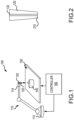
FIG. 1 illustrates a perspective view of a directed energy deposition (DED) system configured to repair an aerospace component, in accordance with various embodiments. -
FIG. 2 illustrates a cross-sectional view of an extruder for a manufacturing system, in accordance with various embodiments. -
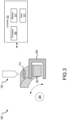
FIG. 3 illustrates a perspective view of a system to heat an aerospace component during direct energy deposition repair, in accordance with various embodiments -
FIG. 4 illustrates a perspective view of a system to heat an aerospace component during direct energy deposition repair, in accordance with various embodiments. -
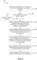
FIG. 5 illustrates a flow diagram of a method for reducing or preventing damage to a component during repair of the component is illustrated in accordance with various embodiments - The detailed description of embodiments herein makes reference to the accompanying drawings, which show embodiments by way of illustration. While these embodiments are described in sufficient detail to enable those skilled in the art to practice the disclosure, it should be understood that other embodiments may be realized and that logical, chemical, and mechanical changes may be made without departing from the spirit and scope of the disclosure. Thus, the detailed description herein is presented for purposes of illustration only and not for limitation. For example, any reference to singular includes plural embodiments, and any reference to more than one component or step may include a singular embodiment or step. Also, any reference to attached, fixed, connected or the like may include permanent, removable, temporary, partial, full and/or any other possible attachment option. Further, any steps in a method discussed herein may be performed in any suitable order or combination.
- In aerospace, directed energy deposition (DED) utilizes guiding energy, which acts as a laser that focuses on a specific area where metal powders or wire feedstocks are heated up and deposited after melting. That is, typically, a small, localized area of the surface of the substrate is melted by the laser and powder or push wire is fed into the melt pool. However, certain high temperature capable metallic alloys used in aerospace that could be repaired using DED processing are known to crack during the DED processing. Accordingly, there is a need to control the processing temperature and environmental conditions during DED processing in order to prevent or reduce damage with certain high temperature capable metallic alloys during the DED processing.
- Disclosed herein is method and system to heat an aerospace component during direct energy deposition repair. In various embodiments, the heating is performed via induction heating. In various embodiments, local heating of the component using a conforming induction heating coil enables processing for repair via DED. In various embodiments, the heating of the substrate during DED processing allows metallic alloys with high temperature strength to be repaired with a reduced occurrence of presenting a defect, such as cracking. In various embodiments, a geometry of the feature being processed will dictate the geometry of the induction coil. In various embodiments, the geometry of the coil provides free rotation of an axisymmetric component during processing via DED. Referring now to
FIG. 1 , a perspective view of a directed energy deposition (DED)system 100 configured to repair an aerospace component is illustrated, in accordance with various embodiments. TheDED system 100, which may also be referred to as a DED device, includes a 3-axis positioning system 110, anozzle 120, a computer numerical control (CNC) controlled table 150, alaser 130, and acontroller 160. In various embodiments, thenozzle 120 is co-axial with thelaser 130 with thelaser 130 in the center and powder delivery achieved via thenozzle 120 around thelaser 130. In various embodiments, the 3-axis positioning system 110 extends from afixed end 112 to amoveable end 114. Thenozzle 120 andlaser 130 are coupled to themoveable end 114 and configured to move with themoveable end 114. In various embodiments, the 3-axis positioning system 110 is in electrical or wireless communication with thecontroller 160, which is configured to control a position of the 3-axis positioning system 110 during DED processing. In various embodiments, a component underrepair 140 may be affixed to the CNC controlled table 150 and positioned under thenozzle 120 andlaser 130 under the control ofcontroller 160. - In various embodiments, the
nozzle 120 and thelaser 130 are disposed at the distal end of the 3-axis positioning system 110. With reference now toFIG. 2 , thenozzle 120 may comprise anannulus 210. In various embodiments, solid powder may be fed through theannulus 210 in thenozzle 120. In various embodiments, melting of the powder occurs when the powder arrives at the melt pool on the substrate that is created by thelaser 130. In various embodiments, the powder may be introduced to thenozzle 120 from a hopper and is carried via a stream of gas to the melt pool. In various embodiments, solid wire may be fed through theannulus 210 in thenozzle 120. In various embodiments, melting of the wire occurs when the wire arrives at the melt pool on the substrate that is created by thelaser 130. In various embodiments, the wire may be introduced to thenozzle 120 via a reel and fed to the melt pool. In various embodiments, feeding of the powder or the wire to thenozzle 120 is controlled by thecontroller 160 fromFIG. 1 . In various embodiments, thenozzle 120 described herein may be one of a plurality of nozzles with varying annulus diameters, so the nozzles of theDED system 100 fromFIG. 2 may enable a higher deposition rate and/or an improved surface finish and feature resolution relative to typical additive manufacturing systems. - Referring now to
FIG. 3 , a perspective view of asystem 300 to heat an aerospace component during direct energy deposition repair is illustrated, in accordance with various embodiments. In various embodiments, the component may have a cross-sectional geometry, such as square or round, among others, and may have a lengthwise geometry, such as straight or curved, among others, along a length of thecomponent 302. With specific reference tocomponent 302 ofFIG. 3 , thecomponent 302 is shown to have a square cross-sectional geometry and to have a curved lengthwise geometry along the length of thecomponent 302. In various embodiments,system 300 includes theDED system 100, aninduction coil 304, arotational motor 306, and acontroller 160 that that is in communication with theDED system 100, theinduction coil 304, and therotational motor 306 and is configured to control theDED system 100, theinduction coil 304, and therotational motor 306. - In various embodiments,
controller 160 may include one ormore processors 308 configured to implement various logical operations in response to execution of instructions, for example, instructions stored on a non-transitory, tangible, computer-readable medium. The one or more processors can be a general-purpose processor, a microprocessor, a microcontroller, a digital signal processor (DSP), an application specific integrated circuit (ASIC), a field programmable gate array (FPGA) or other programmable logic device, discrete or transistor logic, discrete hardware components, or any combination thereof. -
Controller 160 may further include amemory 310 to store data, executable instructions, system program instructions, and/or controller instructions to implement the control logic ofcontroller 160.Memory 310 may further store a database, a look up table, and/or other data objects for use by the executable instructions for implementing the control logic ofcontroller 160. System program instructions and/or controller instructions may be loaded onto a non-transitory, tangible computer-readable medium having instructions stored thereon that, in response to execution by a controller, cause the controller to perform various operations. The term "non-transitory" is to be understood to remove only propagating transitory signals per se from the claim scope and does not relinquish rights to all standard computer-readable media that are not only propagating transitory signals per se. -
Controller 160 may further include aninput 312. In various embodiments,input 312 may be a bus or communication protocol with another device. In various embodiments,input 312 may be a touch screen, keyboard, and/or other input device located on theDED system 100, theinduction coil 304, and therotational motor 306. In various embodiments,input 312 may be a network connection for receiving inputs via a network connected device. -
Controller 160 is configured to communicate with and control theDED system 100, theinduction coil 304, and therotational motor 306.Controller 160 may send instructions to theDED system 100, theinduction coil 304, and therotational motor 306 to control the working parameters of theDED system 100, theinduction coil 304, and therotational motor 306. In various embodiments, the instructions may be stored inmemory 310 as a computer numerical control (CNC) program. The working parameters may include the RPM at which thecomponent 302 is rotated, the direction in which thecomponent 302 is rotated, the deposition speed of the material onto thecomponent 302, and the electric current needed to heat thecomponent 302 to a desired temperature. In various embodiments, the working parameters may be received viainput 312. In various embodiments, the working parameters may be derived from input received viainput 312. For example,input 312 may receive a type of metal of thecomponent 302 and/or a thickness or diameter of thecomponent 302, among other input information. - In various embodiments,
controller 160 may use the input information to determine the working parameters to send to theDED system 100, theinduction coil 304, and therotational motor 306. In various embodiments,controller 160, and, more specifically,memory 310, may store a database of working parameters for different material types, thicknesses, and diameters. For example,controller 160 may send a first set of working parameters to theDED system 100, theinduction coil 304, and therotational motor 306 in response to the input indicating that thecomponent 302 is formed from a first metallic alloy having a first thickness. As another example,controller 160 may send a second set of working parameters, with at least one parameter being different, to theDED system 100, theinduction coil 304, and therotational motor 306 in response to the input indicating that the thickness of thecomponent 302 is a second thickness that is different than the first thickness. - By adjusting the working parameters (e.g., RPM, direction, deposition speed, electric current, etc.) for different materials and sized materials,
controller 160, theDED system 100, theinduction coil 304, and therotational motor 306 may deposit material having different thicknesses to repair thecomponent 302. Adjusting the working parameters of theDED system 100, theinduction coil 304, and therotational motor 306 by thecontroller 160 allows for a uniform and consistent workpiece. Thecomponent 302 is preheated by theinduction coil 304 before deposition by theDED system 100 thereby reducing any damage that may be incurred by the deposition process. In various embodiments, theinduction coil 304 may a magnetic field via an electrical current to heat thecomponent 302, the electrical current being either an alternating electrical current or a direct electrical current. In that regard, in various embodiments, theinduction coil 304 may have a geometry that resemble the features of thecomponent 302. Accordingly, in various embodiments, if thecomponent 302 has substantially a square geometry, then theinduction coil 304 may have substantially square geometry. Accordingly, in various embodiments, if thecomponent 302 has substantially a circular geometry, then theinduction coil 304 may have substantially circular geometry. In various embodiments, theinduction coil 304 may be configured to heat one or more sides of thecomponent 302. In that regard, in various embodiments, theinduction coil 304 may be configured to heat only two sides of thecomponent 302, i.e. a top and bottom of thecomponent 302. In various embodiments, theinduction coil 304 may be configured to heat all four sides of thecomponent 302. - With further regard to
FIG. 3 , in various embodiments, thecontroller 160 may receive a first input indicating a type of metallic alloy of acomponent 302 that is being repaired. Based on the identified type of metallic alloy, in various embodiments, thecontroller 160 may identify by accessing thememory 310 that the metallic alloy is a high temperature capable metallic alloy that requires heating to prevent or reduce damage to thecomponent 302. In various embodiments, thecontroller 160 may then identify from thememory 310 the temperature required to heat thecomponent 302 based on the identified metallic alloy to prevent or reduce damage to thecomponent 302. In various embodiments, thecomponent 302 may be coupled to therotational motor 306 in various manners, such as being affixed to a table that is controlled byrotational motor 306 or affixed to a spoke-like element that is controlled byrotational motor 306, among others. Once thecontroller 160 identifies the temperature, in various embodiments, thecontroller 160 may be configured to send a command to therotational motor 306 to rotate thecomponent 302 in one or more directions and at a specific speed into and out theinduction coil 304 as well as send a command to theinduction coil 304 to apply a magnetic field sufficient to increase a temperature of arepair area 314 of thecomponent 302. In various embodiments, thecontroller 160 may monitor one or more sensors, such as an infrared sensor, to monitor the temperature of thecomponent 302. In various embodiments, once thecomponent 302 is heated to the required temperature as identified by the one or more sensors, thecontroller 160 may send a command to therotational motor 306 to rotate thecomponent 302 in one or more directions and at a specific speed to theDED system 100 and send a command to theDED system 100 to repair therepair area 314 of thecomponent 302. During the repair process, in various embodiments, thecontroller 160 may continue to monitor the temperature of therepair area 314 of thecomponent 302 and rotate the component between theinduction coil 304 and theDED system 100 in order that theinduction coil 304 maintains the desired temperature of thecomponent 302 so as prevent or reduce damage of thecomponent 302 until the repair is made to thecomponent 302 by theDED system 100. - Referring now to
FIG. 4 , a perspective view of asystem 400 to heat an aerospace component during direct energy deposition repair is illustrated, in accordance with various embodiments.FIG. 4 is similar toFIG. 3 with the exception of the table motor ofFIG. 3 being a rotational motor and the table motor ofFIG. 4 being a translational motor. Therefore, elements inFIG. 4 not specifically described inFIG. 4 operate in a similar manner to the elements described inFIG. 3 . With specific reference tocomponent 402 ofFIG. 4 , thecomponent 402 is shown to have a square cross-sectional geometry and to have a straight lengthwise geometry along the length of thecomponent 402. In various embodiments,system 400 includes theDED system 100, aninduction coil 404, atranslational motor 406, and acontroller 160 that that is in communication with theDED system 100, theinduction coil 404, and thetranslational motor 406 and is configured to control theDED system 100, theinduction coil 404, and thetranslational motor 406.Controller 160 may further include aninput 312. In various embodiments,input 312 may be a bus or communication protocol with another device. In various embodiments,input 312 may be a touch screen, keyboard, and/or other input device located on theDED system 100, theinduction coil 404, and thetranslational motor 406. In various embodiments,input 312 may be a network connection for receiving inputs via a network connected device. -
Controller 160 is configured to communicate with and control theDED system 100, theinduction coil 404, and thetranslational motor 406.Controller 160 may send instructions to theDED system 100, theinduction coil 404, and thetranslational motor 406 to control the working parameters of theDED system 100, theinduction coil 404, and thetranslational motor 406. In various embodiments, the instructions may be stored inmemory 310 as a computer numerical control (CNC) program. The working parameters may include the RPM at which thecomponent 402 is translated, the direction in which thecomponent 402 is translated, the deposition speed of the material onto thecomponent 402, and the electric current needed to heat thecomponent 402 to a desired heat. In various embodiments, the working parameters may be received viainput 312. In various embodiments, the working parameters may be derived from input received viainput 312. For example,input 312 may receive a type of metal of thecomponent 402 and/or a thickness or diameter of thecomponent 402, among other input information. - In various embodiments,
controller 160 may use the input information to determine the working parameters to send to theDED system 100, theinduction coil 404, and thetranslational motor 406. In various embodiments,controller 160, and, more specifically,memory 310, may store a database of working parameters for different material types, thicknesses, and diameters. For example,controller 160 may send a first set of working parameters to theDED system 100, theinduction coil 404, and thetranslational motor 406 in response to the input indicating that thecomponent 402 is formed from a first metallic alloy having a first thickness. As another example,controller 160 may send a second set of working parameters, with at least one parameter being different, to theDED system 100, theinduction coil 404, and thetranslational motor 406 in response to the input indicating that the thickness of thecomponent 402 is a second thickness that is different than the first thickness. - By adjusting the working parameters (e.g., RPM, direction, deposition speed, electric current, etc.) for different materials and sized materials,
controller 160, theDED system 100, theinduction coil 404, and thetranslational motor 406 may deposit material having different thicknesses to repair thecomponent 402. Adjusting the working parameters of theDED system 100, theinduction coil 404, and thetranslational motor 406 by thecontroller 160 allows for a uniform and consistent workpiece. Thecomponent 402 is preheated by theinduction coil 404 before deposition by theDED system 100 thereby reducing any damage that may be incurred by the deposition process. In various embodiments, theinduction coil 404 may apply a magnetic field via an electrical current to heat thecomponent 402, the electrical current being either an alternating electrical current or a direct electrical current. In that regard, in various embodiments, theinduction coil 404 may have a geometry that resemble the features of thecomponent 402. Accordingly, in various embodiments, if thecomponent 402 has substantially a square geometry, then theinduction coil 404 may have substantially square geometry. Accordingly, in various embodiments, if thecomponent 402 has substantially a circular geometry, then theinduction coil 404 may have substantially circular geometry. In various embodiments, theinduction coil 404 may be configured to heat one or more sides of thecomponent 402. In that regard, in various embodiments, theinduction coil 404 may be configured to heat only two sides of thecomponent 402, i.e. a top and bottom of thecomponent 402. In various embodiments, theinduction coil 404 may be configured to heat all four sides of thecomponent 402. - With further regard to
FIG. 4 , in various embodiments, thecontroller 160 may receive a first input indicating a type of metallic alloy of acomponent 402 that is being repaired. Based on the identified type of metallic alloy, in various embodiments, thecontroller 160 may identify by accessing thememory 310 that the metallic alloy is a high temperature capable metallic alloy that requires heating to prevent or reduce damage to thecomponent 402. In various embodiments, thecontroller 160 may then identify from thememory 310 the temperature required to heat thecomponent 402 based on the identified metallic alloy to prevent or reduce damage to thecomponent 402. In various embodiments, thecomponent 402 may be coupled to thetranslational motor 406 in various manners, such as being affixed to a table that is controlled bytranslational motor 406 or affixed to a spoke-like element that is controlled byrotational motor 306, among others. Once thecontroller 160 identifies the temperature, in various embodiments, thecontroller 160 may be configured to send a command to thetranslational motor 406 to translate thecomponent 402 in one or more directions and at a specific speed into and out theinduction coil 404 as well as send a command to theinduction coil 404 to apply a magnetic field sufficient to increase a temperature of arepair area 414 of thecomponent 402. It is noted that in difference toFIG. 3 , theinduction coil 404 inFIG. 4 is a set of induction coils so that thecomponent 402 may be heated in either direction. In various embodiments, thecontroller 160 may monitored one or more sensors, such as an infrared sensor, to monitor the temperature of thecomponent 402. In various embodiments, once thecomponent 402 is heated to the required temperature as identified by the one or more sensors, thecontroller 160 may send a command to thetranslational motor 406 to translate thecomponent 402 in one or more directions and at a specific speed to theDED system 100 and send a command to theDED system 100 to repair therepair area 414 of thecomponent 402. During the repair process, in various embodiments, thecontroller 160 may continue to monitor the temperature of therepair area 414 of thecomponent 402 and translate the component between theinduction coil 404 and theDED system 100 in order that theinduction coil 404 maintains the desired temperature of thecomponent 402 so as prevent or reduce damage of thecomponent 402 until the repair is made to thecomponent 402 by theDED system 100. - Referring now to
FIG. 5 , a flow diagram of amethod 500 for reducing or preventing damage to a component during repair of the component is illustrated in accordance with various embodiments. Atblock 502, a controller, such ascontroller 160 ofFIGS. 1 ,3 , and4 , receives input indicating a type of metallic alloy of the component that is being repaired. Atblock 504, the controller determines whether the alloy is a high temperature capable alloy that requires heating to prevent or reduce damage to the component. If atblock 504 the controller determines that the allow is not a high temperature capable alloy, then atblock 505 the operation continues the standard process without the use of induction heating. - If at
block 504 the controller determines that the allow is a high temperature capable alloy, then atblock 506 the controller identifies a temperature required to heat the component based on the identified alloy to prevent or reduce damage to the component. Atblock 508, the controller sends a command to a motor to move the component in one or more directions and at a specific speed into and out an induction coil. Atblock 510, the controller sends a command to the induction coil to apply a magnetic field sufficient to increase a temperature of a repair area of component to prevent or reduce damage to the component. Atblock 512, once the component is heated to the required temperature, as identified by one or more sensors, the controller send a command to the motor to move the component in one or more directions and at a specific speed to a DED system. Atblock 514, the controller sends a command to the DED system to repair the repair area of the component. - Benefits and other advantages have been described herein with regard to specific embodiments. Furthermore, the connecting lines shown in the various figures contained herein are intended to represent exemplary functional relationships and/or physical couplings between the various elements. It should be noted that many alternative or additional functional relationships or physical connections may be present in a practical system. However, the benefits, advantages, solutions to problems, and any elements that may cause any benefit, advantage, or solution to occur or become more pronounced are not to be construed as critical, required, or essential features or elements of the disclosure. The scope of the disclosure is accordingly to be limited by nothing other than the appended claims, in which reference to an element in the singular is not intended to mean "one and only one" unless explicitly so stated, but rather "one or more." Moreover, where a phrase similar to "at least one of A, B, or C" is used in the claims, it is intended that the phrase be interpreted to mean that A alone may be present in an embodiment, B alone may be present in an embodiment, C alone may be present in an embodiment, or that any combination of the elements A, B and C may be present in a single embodiment; for example, A and B, A and C, B and C, or A and B and C.
- Systems, methods, and apparatus are provided herein. In the detailed description herein, references to "one embodiment," "an embodiment," "an example embodiment," etc., indicate that the embodiment described may include a particular feature, structure, or characteristic, but every embodiment may not necessarily include the particular feature, structure, or characteristic. Moreover, such phrases are not necessarily referring to the same embodiment. Further, when a particular feature, structure, or characteristic is described in connection with an embodiment, it is submitted that it is within the knowledge of one skilled in the art to affect such feature, structure, or characteristic in connection with other embodiments whether or not explicitly described. After reading the description, it will be apparent to one skilled in the relevant art(s) how to implement the disclosure in alternative embodiments.
- Furthermore, no element, component, or method step in the present disclosure is intended to be dedicated to the public regardless of whether the element, component, or method step is explicitly recited in the claims. No claim element herein is intended to invoke 35 U.S.C. 112(f) unless the element is expressly recited using the phrase "means for." As used herein, the terms "comprises," "comprising," or any other variation thereof, are intended to cover a non-exclusive inclusion, such that a process, method, article, or apparatus that comprises a list of elements does not include only those elements but may include other elements not expressly listed or inherent to such process, method, article, or apparatus.
Claims (15)
- A method for repairing a component without further damaging the component, comprising:applying a magnetic field to the component via an induction coil thereby causing a temperature of the component to increase; andresponsive to the component reaching a desired temperature, repairing the component via a direct energy deposition process.
- The method of claim 1, wherein the induction coil is powered via an electrical current and wherein the electrical current is at least one of a direct electrical current or an alternating electrical current.
- The method of claim 1 or 2,wherein the induction coil is a single coil, and/orwherein the induction coil is a set of coils.
- The method of claim 1, 2 or 3, wherein the component is a high temperature capable metallic alloy component.
- The method of claim 4, wherein an amount of the heat applied to the component is dependent on a type of metallic alloy of the high temperature capable metallic alloy component.
- The method of any preceding claim, wherein the desired temperature is determined via a set of sensors monitoring a temperature of the component as the component is heated via the induction coil.
- The method of any preceding claim, wherein the component is moved into and out the induction coil via a motor.
- The method of claim 7, wherein the component is moved into and out an extruder of a direct energy deposition system via the motor.
- The method of claim 8, wherein the movement of the component is at least one of a rotational movement or a translational movement.
- A system, comprising:a direct energy deposition device;an induction coil;a controller; anda tangible, non-transitory memory configured to communicate with the controller, the tangible, non-transitory memory having instructions stored thereon that, in response to execution by the controller, cause the controller to perform operations comprising:commanding the induction coil to apply a magnetic field to a component thereby causing a temperature of the component to increase; andresponsive to the component reaching a desired temperature, commanding the direct energy deposition device to repair the component.
- The system of claim 10, wherein the induction coil is powered via an electrical current and wherein the electrical current is at least one of a direct electrical current or an alternating electrical current, and/orwherein the induction coil is a single coil, and/orwherein the induction coil is a set of coils.
- The system of claim 10 or 11, wherein the component is a high temperature capable metallic alloy component.
- The system of any of claims 10 to 12, wherein the controller controls an amount of the heat applied to the component dependent on a type of metallic alloy of the high temperature capable metallic alloy component.
- The system of any of claims 10 to 13 , wherein the system further comprises:
a set of sensors, wherein the desired temperature is determined via the set of sensors monitoring a temperature of the component as the component is heated via the induction coil. - The system of any of claims 10 to 14, wherein the system further comprises:a motor, wherein the motor moves the component is moved into and out of the induction coil,wherein, optionally, the motor moves the component into and out an extruder of a direct energy deposition system,wherein, optionally, the movement of the component is at least one of a rotational movement or a translational movement.
Applications Claiming Priority (1)
| Application Number | Priority Date | Filing Date | Title |
|---|---|---|---|
| US18/351,102 US20250024563A1 (en) | 2023-07-12 | 2023-07-12 | Induction heating of a component during direct energy deposition repair |
Publications (1)
| Publication Number | Publication Date |
|---|---|
| EP4494785A1 true EP4494785A1 (en) | 2025-01-22 |
Family
ID=91829117
Family Applications (1)
| Application Number | Title | Priority Date | Filing Date |
|---|---|---|---|
| EP24186457.8A Pending EP4494785A1 (en) | 2023-07-12 | 2024-07-04 | Induction heating of a component during direct energy deposition repair |
Country Status (2)
| Country | Link |
|---|---|
| US (1) | US20250024563A1 (en) |
| EP (1) | EP4494785A1 (en) |
Citations (3)
| Publication number | Priority date | Publication date | Assignee | Title |
|---|---|---|---|---|
| US20150064050A1 (en) * | 2012-04-13 | 2015-03-05 | MTU Aero Engines AG | Multiple coil arrangement for a device for generative production of components and corresponding production method |
| EP3718679A1 (en) * | 2019-04-05 | 2020-10-07 | United Technologies Corporation | Weld repair system |
| US20220143900A1 (en) * | 2020-11-09 | 2022-05-12 | Sprit AeroSystems, Inc. | Method and apparatus for in-situ thermal management and heat treatment of additively manufacturing components |
Family Cites Families (2)
| Publication number | Priority date | Publication date | Assignee | Title |
|---|---|---|---|---|
| DE10137776C1 (en) * | 2001-08-02 | 2003-04-17 | Fraunhofer Ges Forschung | Process for the production of wear-resistant surface layers |
| IL283302B2 (en) * | 2021-05-19 | 2023-05-01 | Magnus Metal Ltd | Additive casting deposition systems and methods |
-
2023
- 2023-07-12 US US18/351,102 patent/US20250024563A1/en active Pending
-
2024
- 2024-07-04 EP EP24186457.8A patent/EP4494785A1/en active Pending
Patent Citations (3)
| Publication number | Priority date | Publication date | Assignee | Title |
|---|---|---|---|---|
| US20150064050A1 (en) * | 2012-04-13 | 2015-03-05 | MTU Aero Engines AG | Multiple coil arrangement for a device for generative production of components and corresponding production method |
| EP3718679A1 (en) * | 2019-04-05 | 2020-10-07 | United Technologies Corporation | Weld repair system |
| US20220143900A1 (en) * | 2020-11-09 | 2022-05-12 | Sprit AeroSystems, Inc. | Method and apparatus for in-situ thermal management and heat treatment of additively manufacturing components |
Non-Patent Citations (1)
| Title |
|---|
| GROUP MESSE FRANKFURT: "ENTDECKE DIE WELT DER ADDITIVEN FERTIGUNG Eine praktische Orientierungshilfe für die spannende Welt der generativen Fertigung", 6 September 2022 (2022-09-06), XP093232383, Retrieved from the Internet <URL:https://formnext.mesago.com/frankfurt/en/industry-insights/am-field-guide/am_other_materials.html> [retrieved on 20241210] * |
Also Published As
| Publication number | Publication date |
|---|---|
| US20250024563A1 (en) | 2025-01-16 |
Similar Documents
| Publication | Publication Date | Title |
|---|---|---|
| EP3597342B1 (en) | Manufacturing method, manufacturing system, and manufacturing program for additive manufactured object | |
| JP6529088B2 (en) | Preparation process and production system of copper-aluminum composite by isothermal method | |
| US10525550B2 (en) | Machine tool, measurement apparatus, method for generating working data, cladding method, method for setting temperature of a workpiece | |
| CN107206536B (en) | Additive Manufacturing of Metal Structures | |
| US20190160594A1 (en) | Methods and systems for additive tool manufacturing | |
| Chabot et al. | Towards a multi-sensor monitoring methodology for AM metallic processes | |
| EP3459673B1 (en) | Additive manufacturing in situ stress relief | |
| KR20180061135A (en) | Surface Treatment in Lamination Manufacturing Using Laser and Gas Flow | |
| Hölscher et al. | Detection of the contact tube to working distance in wire and arc additive manufacturing | |
| US20250024563A1 (en) | Induction heating of a component during direct energy deposition repair | |
| EP3495083A1 (en) | Methods and systems for additive manufacturing | |
| CN107900339B (en) | Ultrasonic vibration 3D printing device and printing method | |
| JP2017113820A (en) | Wire electric discharge machine including core fixing determination function | |
| US20220227052A1 (en) | In situ deposition debinding and sintering or melting of strategically deposited media for an improved additive manufacturing process | |
| EP4349520A1 (en) | Corrosion protection using metallic coating | |
| EP4410467A1 (en) | Field-assisted friction stir additive manufacturing | |
| US20170106473A1 (en) | Pressure vessel | |
| US20220105684A1 (en) | Micro-welding using a three-dimensional printer | |
| CN116618819B (en) | Heterogeneous metal inertia friction welding preheating equipment and use method | |
| US10427246B2 (en) | Indirect surface finishing during hybrid manufacturing | |
| EP4021726B1 (en) | A powder bed additive manufacturing machine | |
| EP1614501B1 (en) | Method and device for thermically deforming a tool holder | |
| US12390878B2 (en) | System and method for metal forming and layering using inductive heating | |
| US20250312860A1 (en) | Method and apparatus for manufacturing a metal structure | |
| WO2024210798A1 (en) | Laser metal deposition device with wire force detection by a multi-axis force sensor and method |
Legal Events
| Date | Code | Title | Description |
|---|---|---|---|
| PUAI | Public reference made under article 153(3) epc to a published international application that has entered the european phase |
Free format text: ORIGINAL CODE: 0009012 |
|
| STAA | Information on the status of an ep patent application or granted ep patent |
Free format text: STATUS: THE APPLICATION HAS BEEN PUBLISHED |
|
| AK | Designated contracting states |
Kind code of ref document: A1 Designated state(s): AL AT BE BG CH CY CZ DE DK EE ES FI FR GB GR HR HU IE IS IT LI LT LU LV MC ME MK MT NL NO PL PT RO RS SE SI SK SM TR |
|
| STAA | Information on the status of an ep patent application or granted ep patent |
Free format text: STATUS: REQUEST FOR EXAMINATION WAS MADE |
|
| 17P | Request for examination filed |
Effective date: 20250721 |