EP4494734A1 - Method for producing filter - Google Patents
Method for producing filter Download PDFInfo
- Publication number
- EP4494734A1 EP4494734A1 EP23795879.8A EP23795879A EP4494734A1 EP 4494734 A1 EP4494734 A1 EP 4494734A1 EP 23795879 A EP23795879 A EP 23795879A EP 4494734 A1 EP4494734 A1 EP 4494734A1
- Authority
- EP
- European Patent Office
- Prior art keywords
- catalyst
- filter
- catalyst slurry
- contact angle
- filter cloth
- Prior art date
- Legal status (The legal status is an assumption and is not a legal conclusion. Google has not performed a legal analysis and makes no representation as to the accuracy of the status listed.)
- Pending
Links
Images







Classifications
-
- B—PERFORMING OPERATIONS; TRANSPORTING
- B01—PHYSICAL OR CHEMICAL PROCESSES OR APPARATUS IN GENERAL
- B01D—SEPARATION
- B01D53/00—Separation of gases or vapours; Recovering vapours of volatile solvents from gases; Chemical or biological purification of waste gases, e.g. engine exhaust gases, smoke, fumes, flue gases, aerosols
- B01D53/34—Chemical or biological purification of waste gases
- B01D53/74—General processes for purification of waste gases; Apparatus or devices specially adapted therefor
- B01D53/86—Catalytic processes
- B01D53/8621—Removing nitrogen compounds
- B01D53/8625—Nitrogen oxides
-
- B—PERFORMING OPERATIONS; TRANSPORTING
- B01—PHYSICAL OR CHEMICAL PROCESSES OR APPARATUS IN GENERAL
- B01D—SEPARATION
- B01D39/00—Filtering material for liquid or gaseous fluids
- B01D39/08—Filter cloth, i.e. woven, knitted or interlaced material
-
- B—PERFORMING OPERATIONS; TRANSPORTING
- B01—PHYSICAL OR CHEMICAL PROCESSES OR APPARATUS IN GENERAL
- B01D—SEPARATION
- B01D39/00—Filtering material for liquid or gaseous fluids
- B01D39/08—Filter cloth, i.e. woven, knitted or interlaced material
- B01D39/083—Filter cloth, i.e. woven, knitted or interlaced material of organic material
-
- B—PERFORMING OPERATIONS; TRANSPORTING
- B01—PHYSICAL OR CHEMICAL PROCESSES OR APPARATUS IN GENERAL
- B01D—SEPARATION
- B01D46/00—Filters or filtering processes specially modified for separating dispersed particles from gases or vapours
- B01D46/0001—Making filtering elements
-
- B—PERFORMING OPERATIONS; TRANSPORTING
- B01—PHYSICAL OR CHEMICAL PROCESSES OR APPARATUS IN GENERAL
- B01D—SEPARATION
- B01D53/00—Separation of gases or vapours; Recovering vapours of volatile solvents from gases; Chemical or biological purification of waste gases, e.g. engine exhaust gases, smoke, fumes, flue gases, aerosols
- B01D53/34—Chemical or biological purification of waste gases
- B01D53/92—Chemical or biological purification of waste gases of engine exhaust gases
- B01D53/94—Chemical or biological purification of waste gases of engine exhaust gases by catalytic processes
- B01D53/9404—Removing only nitrogen compounds
- B01D53/9409—Nitrogen oxides
-
- B—PERFORMING OPERATIONS; TRANSPORTING
- B01—PHYSICAL OR CHEMICAL PROCESSES OR APPARATUS IN GENERAL
- B01J—CHEMICAL OR PHYSICAL PROCESSES, e.g. CATALYSIS OR COLLOID CHEMISTRY; THEIR RELEVANT APPARATUS
- B01J21/00—Catalysts comprising the elements, oxides, or hydroxides of magnesium, boron, aluminium, carbon, silicon, titanium, zirconium, or hafnium
- B01J21/06—Silicon, titanium, zirconium or hafnium; Oxides or hydroxides thereof
- B01J21/063—Titanium; Oxides or hydroxides thereof
-
- B—PERFORMING OPERATIONS; TRANSPORTING
- B01—PHYSICAL OR CHEMICAL PROCESSES OR APPARATUS IN GENERAL
- B01D—SEPARATION
- B01D2239/00—Aspects relating to filtering material for liquid or gaseous fluids
- B01D2239/04—Additives and treatments of the filtering material
- B01D2239/0407—Additives and treatments of the filtering material comprising particulate additives, e.g. adsorbents
-
- B—PERFORMING OPERATIONS; TRANSPORTING
- B01—PHYSICAL OR CHEMICAL PROCESSES OR APPARATUS IN GENERAL
- B01D—SEPARATION
- B01D2239/00—Aspects relating to filtering material for liquid or gaseous fluids
- B01D2239/04—Additives and treatments of the filtering material
- B01D2239/0471—Surface coating material
- B01D2239/0492—Surface coating material on fibres
-
- B—PERFORMING OPERATIONS; TRANSPORTING
- B01—PHYSICAL OR CHEMICAL PROCESSES OR APPARATUS IN GENERAL
- B01D—SEPARATION
- B01D2255/00—Catalysts
- B01D2255/20—Metals or compounds thereof
- B01D2255/207—Transition metals
- B01D2255/20707—Titanium
-
- B—PERFORMING OPERATIONS; TRANSPORTING
- B01—PHYSICAL OR CHEMICAL PROCESSES OR APPARATUS IN GENERAL
- B01D—SEPARATION
- B01D2258/00—Sources of waste gases
- B01D2258/01—Engine exhaust gases
-
- B—PERFORMING OPERATIONS; TRANSPORTING
- B01—PHYSICAL OR CHEMICAL PROCESSES OR APPARATUS IN GENERAL
- B01D—SEPARATION
- B01D2258/00—Sources of waste gases
- B01D2258/02—Other waste gases
- B01D2258/0283—Flue gases
-
- B—PERFORMING OPERATIONS; TRANSPORTING
- B01—PHYSICAL OR CHEMICAL PROCESSES OR APPARATUS IN GENERAL
- B01J—CHEMICAL OR PHYSICAL PROCESSES, e.g. CATALYSIS OR COLLOID CHEMISTRY; THEIR RELEVANT APPARATUS
- B01J35/00—Catalysts, in general, characterised by their form or physical properties
- B01J35/50—Catalysts, in general, characterised by their form or physical properties characterised by their shape or configuration
- B01J35/56—Foraminous structures having flow-through passages or channels, e.g. grids or three-dimensional [3D] monoliths
Definitions
- the present disclosure relates to a method for producing a filter.
- Patent Document 1 discloses a method for producing a filter including deriving the relationship between concentration of an organic solvent contained in a catalyst slurry and a supported amount of a catalyst supported on a filter cloth, and determining the concentration of the organic solvent from the target supported amount of a catalyst to be supported on the filter cloth.
- Patent Document 1 JP 2021-133317A
- the method for producing a filter disclosed in Patent Document 1 has the catalyst slurry repelled by the filter cloth and cannot cause the catalyst slurry to sufficiently permeate the filter cloth when the filter cloth has water repellency such as one containing a fluorine fiber.
- an object of at least one embodiment of the present invention is to provide a method for producing a filter in which a catalyst can be supported in a state of being dispersed on the filter cloth.
- a method for producing a filter according to at least one embodiment of the present invention is a method for producing a filter in which a catalyst is supported on a filter cloth. The method includes:
- the wettability of a catalyst slurry with respect to a filter cloth is improved by adjusting the catalyst slurry such that the contact angle of the catalyst slurry with respect to the filter cloth is small.
- the catalyst slurry after the adjustment has a larger contact area with the filter cloth fiber.
- the catalyst slurry after adjusted to have a small contact angle, the catalyst slurry comes into uniform contact with the filter cloth fiber, the catalyst slurry permeates inside the filter cloth, and the catalyst is supported in a state of being dispersed in the filter cloth fiber.
- FIG. 1 is a conceptual diagram illustrating a contact angle ⁇ of a catalyst slurry (droplet) 3 with respect to a filter cloth 1.
- the contact angle ⁇ of the catalyst slurry (droplet) 3 with respect to the filter cloth 1 illustrated in FIG. 1 is an index for evaluating the wettability of the catalyst slurry 3 with respect to the filter cloth 1.
- a filter cloth containing a fluorine fiber such as polytetrafluoroethylene (hereinafter, called "PTFE”) is water-repellent, even when a water-based catalyst slurry is applied, the catalyst slurry does not permeate the filter cloth, the catalyst aggregates on a surface of the filter cloth, and a uniform and sufficient amount of the catalyst cannot be supported.
- PTFE polytetrafluoroethylene
- the inventors of the present application have found that the contact angle ⁇ of the catalyst slurry 3 with respect to the filter cloth 1 can be controlled by adding a surfactant to the catalyst slurry.
- the inventors of the present application have found that, by controlling the contact angle ⁇ of the catalyst slurry 3 with respect to the filter cloth 1 to become small, even a filter cloth containing a fluorine fiber such as PTFE can be permeated with the catalyst slurry, and a uniform and sufficient amount of catalyst can be supported.
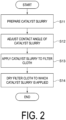
- FIG. 2 is a flowchart schematically showing a method for producing a filter according to the first embodiment.
- the method for producing a filter according to the first embodiment is a method for producing a filter in which a catalyst is supported on a filter cloth, and the filter cloth includes, but is not limited to, a fluorine fiber such as PTFE, for example.
- Examples of the catalyst include, but are not limited to, one containing titanium (Ti) as a component.
- the method for producing a filter according to the first embodiment includes step (S11) of preparing a catalyst slurry, step (S12) of adjusting a contact angle of the catalyst slurry with respect to the filter cloth by adding a surfactant to the catalyst slurry, step (S13) of applying the filter cloth with a catalyst slurry having the contact angle adjusted, and step (S 14) of drying the filter cloth to which the catalyst slurry is applied.
- the surfactant added to the catalyst slurry in step (S 12) of adjusting the contact angle of the catalyst slurry is, but not limited to, an ether type surfactant, for example.
- ether type surfactant examples include, but are not limited to, polyoxyethylene alkyl ether or polyalkylene alkyl ether.
- step (S13) of applying the catalyst slurry to the filter cloth the catalyst slurry is sprayed onto the filter cloth by a spray nozzle (not illustrated).
- step (S13) of applying the catalyst slurry to the filter cloth includes, for example, step (S21) of examining the depth to which the catalyst slurry permeates the filter cloth, step (S22) of adjusting the pressure at which the catalyst slurry is sprayed, and step (S23) of spray-applying (spraying) the catalyst slurry to the filter cloth.
- step (S21) of examining the depth to which the catalyst slurry permeates the filter cloth the depth to which the catalyst slurry permeates the filter cloth is examined, and in step (S22) of adjusting the pressure at which the catalyst slurry is sprayed, the pressure at which the catalyst slurry is sprayed is adjusted.
- the wettability of the catalyst slurry with respect to the filter cloth is improved by adjusting the contact angle of the catalyst slurry with respect to the filter cloth to be small.
- the catalyst slurry after the adjustment has a larger contact area with the filter cloth fiber.
- the catalyst slurry after adjusted to have a small contact angle, the catalyst slurry comes into uniform contact with the filter cloth fiber, the catalyst slurry permeates inside the filter cloth, and the catalyst is supported in a state of being dispersed in the filter cloth fiber.
- the filter cloth is water-repellent because it contains a fluorine fiber, but by adding a surfactant to the catalyst slurry and adjusting the contact angle of the catalyst slurry with respect to the filter cloth to be small, the catalyst slurry can be easily permeated to the filter cloth containing a fluorine fiber.
- the catalyst By permeating the catalyst into the filter cloth containing a fluorine fiber, the catalyst can be supported in a state of being dispersed in the filter cloth fiber even in the filter cloth containing a fluorine fiber.
- FIG. 4 is a flowchart schematically showing step (S12) of adjusting the contact angle of the catalyst slurry according to the second embodiment.
- the method for producing a filter according to the second embodiment specifies step (S12) of adjusting the contact angle of the catalyst slurry with respect to the first embodiment, and step (S11) of preparing the catalyst slurry, step (S13) of applying the filter cloth with a catalyst slurry having the contact angle adjusted, and step (S 14) of drying the filter cloth to which the catalyst slurry is applied are the same as those in the method for producing a filter according to the first embodiment.
- Step (S12) of adjusting the contact angle of the catalyst slurry according to the second embodiment includes step (S31) of acquiring the relationship between the concentration of the surfactant and the contact angle of the catalyst slurry, step (S32) of acquiring the relationship between the contact angle of the catalyst slurry and a supported amount of the catalyst, step (S33) of specifying the supported amount of the catalyst, step (S34) of specifying the contact angle of the catalyst slurry corresponding to the supported amount of the catalyst, step (S35) of specifying the concentration of the surfactant, and step (S36) of adding the surfactant.
- Step (S31) of acquiring the relationship between the concentration of the surfactant and the catalyst slurry contact angle is a step of acquiring the relationship between the concentration of the surfactant contained in the catalyst slurry and the contact angle of the catalyst slurry with respect to the filter cloth.
- the catalyst contained in the catalyst slurry contains titanium (Ti) as a component, the solvent is water, and the slurry concentration of the catalyst slurry is 25 wt.%.
- the relationship between the concentration of the surfactant contained in the catalyst slurry and the contact angle of the catalyst slurry with respect to the filter cloth is obtained by measuring the contact angle of the catalyst slurry with respect to the filter cloth while changing the concentration of the surfactant contained in the catalyst slurry.
- the relationship between the concentration of the surfactant contained in the catalyst slurry and the contact angle of the catalyst slurry (droplet) with respect to the filter cloth is obtained for sodium dioctyl sulfosuccinate, which is an anionic surfactant, and polyoxyethylene alkyl ether, which is an ether type surfactant.
- polyoxyethylene alkyl ether has a larger contact angle reduction effect in a low concentration range than sodium dioctyl sulfosuccinate.
- the surfactant to be added to the catalyst slurry is preferably polyoxyethylene alkyl ether rather than sodium dioctyl sulfosuccinate.
- Step (S32) of acquiring the relationship between the contact angle of the catalyst slurry and a supported amount of the catalyst is a step of acquiring the relationship between the contact angle of the catalyst slurry (droplet) with respect to the filter cloth and the supported amount of a catalyst supported on the filter cloth.
- step (S32) of acquiring the relationship between the contact angle of the catalyst slurry and a supported amount of the catalyst includes step (S41) of measuring the size and mass of the filter cloth, step (S42) of drying the filter cloth, step (S43) of measuring the mass of the filter cloth, step (S44) of preparing the catalyst slurry, step (S45) of spraying the catalyst slurry, step (S46) of drying the filter cloth to which the catalyst slurry is applied, and step (S47) of measuring the mass of the filter (step of measuring the supported amount).
- step (S42) of drying the filter cloth the mass of the filter cloth in a dry state can be measured by drying the filter cloth at 110 °C for one hour, for example.
- step (S44) of preparing the catalyst slurry a catalyst slurry having a different contact angle is prepared by changing the amount of the surfactant added to the catalyst slurry.
- step (S45) of applying the catalyst slurry for example, the nozzle is a one-fluid nozzle, the ejection amount of the catalyst slurry is 1 L/min, the nozzle pattern is elliptical, the spray pressure is 0.08 (0.05 to 0.15) MPa, the spray distance is 40 cm, and the concentration of the catalyst slurry is 25 wt.%.
- step (S46) of drying the filter cloth to which the catalyst slurry is applied the filter cloth is dried at 110 °C for 2 hours, for example.
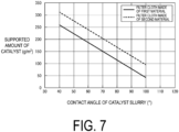
- FIG. 7 is a graph showing the relationship between the contact angle of the catalyst slurry and the catalyst supported amount acquired by the step (steps S41 to S47) of acquiring the relationship between the contact angle of the catalyst slurry and the supported amount of the catalyst.
- the first material shown in FIG. 7 has the highest water repellency among the currently available fluorine-based fibers, and the second material has the lowest water repellency.
- the relationship between the contact angle of the catalyst slurry and the catalyst supported amount can be represented by a straight line, and is in a substantially linear relationship, and therefore it is considered that the contact angle of the currently available fluorine fiber and the catalyst supported amount are in a range sandwiched between the two straight lines.
- Step (S33) of specifying the supported amount of the catalyst shown in FIG. 4 is a step of specifying the supported amount of a catalyst supported on the filter cloth, and is defined based on the required performance of the filter, for example.
- the required performance of the filter includes, for example, differential pressure, necessity of DeNOx performance, and necessity of dioxin decomposition performance.
- Step (S34) of specifying the contact angle of the catalyst slurry corresponding to the supported amount of the catalyst is a step of specifying, based on the relationship with the supported amount of the catalyst, the contact angle of the catalyst slurry corresponding to the supported amount of the catalyst specified.
- the contact angle is specified as 56° from the relationship between the contact angle of the catalyst slurry and the supported amount of the catalyst shown in FIG. 7 .
- the contact angle of the catalyst slurry is specified.
- Step (S35) of specifying the concentration of the surfactant shown in FIG. 4 is a step of acquiring, based on the relationship with the contact angle of the catalyst slurry, the concentration of the surfactant corresponding to the contact angle of the catalyst slurry specified.
- the concentration of the surfactant is specified as 0.1 wt.% from the relationship between the concentration of the surfactant and the contact angle of the catalyst slurry shown in FIG. 5 .
- the concentration of the surfactant is specified.
- Step (S36) of adding the surfactant shown in FIG. 4 is a step of adding the surfactant to the catalyst slurry to have a specified concentration.
- step S36 the surfactant is added to the catalyst slurry prepared in step S11 to have the concentration of the surfactant specified in step 35.
- polyoxyethylene alkyl ether is added to the catalyst slurry prepared in step S11 so that the concentration of polyoxyethylene alkyl ether becomes 0.1 wt.%.
- the catalyst concentration of the catalyst slurry of the example is 25 wt.%
- the additive concentration of the surfactant added to the catalyst slurry is 1.0 wt.%, but the contact angle of the catalyst slurry with respect to the filter cloth is still adjusted by adding the surfactant to the catalyst slurry.
- the concentration of the surfactant added to the catalyst slurry is not limited to 1.0 wt.%, and for example, when the surfactant is polyoxyethylene alkyl ether, the concentration may exceed 1.0 wt.% as long as the concentration is 0.1 wt.% or more.
- FIG. 8 is a view illustrating a filter 10, which is a filter produced by a method for producing a filter according to the comparative example.
- a catalyst slurry in which ethanol is added to a catalyst slurry (solvent is water) prepared to have a concentration of the catalyst of 25 wt.% so that the additive concentration becomes 20 wt.% is sprayed onto a filter cloth made of the first material.
- the contact angle of this catalyst slurry is about 85°.
- the catalyst aggregates on the surface of the filter cloth (the aggregated catalyst is indicated by reference sign 14).
- FIG. 9 is a view illustrating a filter 20, which is a filter produced by a method for producing a filter according to the example.
- surfactant polyoxyethylene alkyl ether
- solvent water
- the contact angle of this catalyst slurry is about 41°.
- the catalyst 24 is supported on a filter cloth fiber 22 in a highly dispersed state on the filter cloth fiber 22 without the catalyst aggregating on the surface of the filter cloth.
- FIG. 10 is a graph showing a catalyst permeation depth (relative catalyst permeation depth) of a surfactant-added catalyst slurry with respect to a catalyst permeation depth of an ethanol-added catalyst slurry.
- the catalyst permeation depth of the surfactant-added catalyst slurry is 1.0.
- the filter onto which the surfactant-added catalyst slurry is sprayed has a larger relative catalyst permeation depth than the filter onto which the ethanol-added catalyst slurry is sprayed (hereinafter, called “filter according to the comparative example”), and the catalyst permeates the filter cloth.
- the adhesion between catalyst particles and the filter cloth fiber 22 is increased as compared with the filter according to the comparative example, and the catalyst is less likely to fall off from the filter cloth.
- the catalyst is dispersed throughout the filter cloth as compared with the filter according to the comparative example, and the catalyst is less likely to aggregate on the surface of the filter cloth.
- the pressure difference (pressure loss) between the upstream side and the downstream side of the filter is smaller than that in the filter according to the comparative example.
- the concentration (additive concentration) of ethanol added to the catalyst slurry is 20 wt.%, and the concentration (additive concentration) of the surfactant added to the catalyst slurry is 1.0 wt.%.
- concentrations are the same as the concentration of ethanol added to the catalyst slurry in the filter (comparative example) illustrated in FIG. 8 and the concentration of the surfactant added to the catalyst slurry in the filter (example) illustrated in FIG. 9 .
- the catalyst is dispersed throughout the filter cloth as compared with the filter according to the comparative example, the contact area of the catalyst in contact with a gas is increased, and the catalyst performance is improved even with the same catalyst and the same supported amount.
- the catalyst can be supported on the filter cloth by adding a surfactant without adding an organic solvent.
- the addition concentration of the surfactant to be added to the catalyst slurry is 1.0 wt.% or less as shown in FIG. 5 , the production cost of the catalyst slurry can be reduced as compared with a case where an organic solvent is added to the catalyst slurry.
- the catalyst slurry in which the addition concentration of the surfactant to be added to the catalyst is equal to or greater than the concentration of the surfactant specified in relation to the contact angle is sprayed onto the filter cloth, the catalyst slurry permeates the inside of the filter cloth fiber, and therefore the catalyst is uniformly supported on the filter cloth fiber while being dispersed in the inside of the filter cloth fiber. Therefore, the adhesion between the catalyst particles and the filter cloth fiber is improved, and the catalyst is less likely to fall off from the filter cloth.
- the pressure difference (pressure loss) between the upstream side and the downstream side of the filter is reduced, and the catalyst performance is improved even with the same catalyst and the same supported amount.
- the catalyst is uniformly supported on the filter cloth fiber while being dispersed in the inside of the filter cloth fiber, the surface area of the catalyst in contact with the gas is increased, and the catalyst performance (DeNOx performance, dioxin decomposition performance, and the like) can be enhanced even with the same catalyst and the same supported amount.
- the exhaust gas treatment device can be made compact.
- FIG. 11 is a flowchart schematically showing step (S12) of adjusting the contact angle of the catalyst slurry according to the third embodiment.
- the method for producing a filter according to the third embodiment specifies step (S12) of adjusting the contact angle of the catalyst slurry with respect to the first embodiment, and step (S11) of preparing the catalyst slurry, step (S13) of applying the filter cloth with a catalyst slurry having the contact angle adjusted, and step (S14) of drying the filter cloth to which the catalyst slurry is applied are the same as those in the method for producing a filter according to the first embodiment.
- step (S12) of adjusting the contact angle of the catalyst slurry according to the third embodiment includes step (S31) of acquiring the relationship between the concentration of the surfactant and the contact angle of the catalyst slurry, step (S52) of acquiring the relationship between the contact angle of the catalyst slurry and a falling-off rate of the catalyst, step (S53) of specifying the falling-off rate of the catalyst, step (S54) of specifying the contact angle of the catalyst slurry corresponding to the falling-off rate of the catalyst, step (S35) of specifying the concentration of the surfactant, and step (S36) of adding the surfactant.
- Step (S31) of acquiring the relationship between the concentration of the surfactant and the contact angle of the catalyst slurry, step (S35) of specifying the concentration of the surfactant, and step (S36) of adding the surfactant are the same as step (S31) of acquiring the relationship between the concentration of the surfactant and the contact angle of the catalyst slurry, step (S35) of specifying the concentration of the surfactant, and step (S36) of adding the surfactant in step (S12) of adjusting the contact angle of the catalyst slurry according to the second embodiment.
- the falling-off rate of the catalyst is obtained by dividing the amount of the catalyst falling by applying forced vibration to a filter cloth (filter) supporting the catalyst by an initial mass.
- Step (S52) of acquiring the relationship between the contact angle of the catalyst slurry and the falling-off rate of the catalyst is a step of acquiring the relationship between the contact angle of the catalyst slurry with respect to the filter cloth and the falling-off rate of the catalyst supported on the filter cloth.
- the relationship between the catalyst falling off amount and the number of times of forced vibration is obtained by simply applying the filter with forced vibration.
- An ultrasonic device is selected as a device for applying the filter with forced vibration.
- the ultrasonic device is, for example, a desktop type, and has an oscillation output of 75 W and a frequency of 28 kHz.
- step (S52) of acquiring the relationship between the contact angle of the catalyst slurry and the falling-off rate of the catalyst includes step (S61) of cutting a filter cloth (filter) on which the catalyst is supported and measuring the size, step (S62) of measuring the mass of the filter, step (S63) of applying the filter with forced vibration, and step (S64) of measuring the mass of the filter.
- step (S61) of cutting the filter and measuring the size for example, the filter is cut into a circular shape.
- step (S63) of applying the filter with forced vibration the forced vibration is applied to a sample holder with a spray side (surface) of the catalyst slurry facing upward, and the forced vibration is applied to the sample holder with the spray side (surface) of the catalyst slurry facing downward.
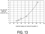
- FIG. 13 shows the relationship between the contact angle and the falling-off rate of the catalyst acquired by the step (steps S61 to S64) of acquiring the relationship between the contact angle of the catalyst slurry and the falling-off rate of the catalyst.
- the falling-off rate is 5%.
- Step (S53) of specifying the falling-off rate of the catalyst shown in FIG. 11 is a step of specifying the falling-off rate of the catalyst supported on the filter cloth, and is specified based on the required performance of the filter.
- the required performance of the filter includes, for example, a replacement period of the filter, a backwashing frequency, a backwashing pressure, and catalyst performance.
- Step (S54) of specifying the contact angle of the catalyst slurry corresponding to the falling-off rate of the catalyst is a step of specifying, based on the relationship with the falling-off rate of the catalyst, the contact angle of the catalyst slurry corresponding to the falling-off rate of the catalyst specified.
- the contact angle is specified as 50° from the relationship between the contact angle of the catalyst slurry and the falling-off rate of the catalyst shown in FIG. 13 .
- the contact angle of the catalyst slurry is specified.
- the contact angle of the catalyst slurry is adjusted through the same operations as in the second embodiment, that is, step (S35) of specifying the concentration of the surfactant and step (S36) of adding the surfactant.
- the replacement period of the filter can be extended.
- step (S12) of adjusting the contact angle of the catalyst slurry has been described as being different, but the contact angle of the catalyst slurry may be adjusted by specifying the concentration of the surfactant based on the supported amount and the falling-off rate of the catalyst and adding the surfactant having the specified concentration to the catalyst slurry.
- a filter 125 produced by the method for producing a filter according to any one of the first to third embodiments is applied to a plant 100 in which an in-furnace DeNOx equipment 120 as illustrated in FIG. 14 is installed.
- the filter 125 installed in the in-furnace DeNOx equipment 120 is a catalyst bag filter also used for DeNOx, and includes an incinerator 110. While ammonia (NH 3 ) for in-furnace DeNOx is injected into the incinerator 110, DeNOx is performed by the catalyst bag filter also used for DeNOx, and leak ammonia (L-NH 3 ) is removed.
- NH 3 ammonia
- L-NH 3 leak ammonia
- the contact area with incineration ash is reduced, and the durability of the filter can be improved (contact with a catalyst poisoning component contained in the incineration ash can be avoided).
- DeNOx can be performed by spraying the reducing agent upstream of the filter.
- the nitrogen oxide (NOx) concentration in combination with in-furnace DeNOx can be reduced, eliminating a DeNOx reaction tower.
- a filter 225 produced by the method for producing a filter according to any one of the first to third embodiments is applied to a plant 200 in which an in-furnace DeNOx equipment 220 and an exhaust gas recirculation device 230 as illustrated in FIG. 15 are installed.
- the filter 225 installed in the in-furnace DeNOx equipment 220 is a catalyst bag filter also used for DeNOx, and includes an incinerator 210. While ammonia for in-furnace DeNOx is injected into the incinerator, the exhaust gas denitrated by the catalyst bag filter also used for DeNOx circulates through the exhaust gas recirculation device 230.
- a reducing agent such as ammonia water or urea water that needs to be evaporated or gasified can be applied.
- a method for producing a filter according to an aspect of [1] is a method for producing a filter in which a catalyst is supported on a filter cloth, the method including:
- Such a production method improves the wettability of a catalyst slurry with respect to a filter cloth by adjusting the catalyst slurry such that the contact angle of the catalyst slurry with respect to the filter cloth is small.
- the catalyst slurry after the adjustment has a larger contact area with the filter cloth fiber.
- the catalyst slurry after adjusted to have a small contact angle, the catalyst slurry comes into uniform contact with the filter cloth fiber, the catalyst slurry permeates inside the filter cloth, and the catalyst is supported in a state of being dispersed in the filter cloth fiber.
- a method for producing a filter according to another aspect is the method for producing a filter according to [1],
- Such a production method can support, by adding the surfactant to the catalyst slurry to have a specified concentration, the catalyst of the specified supported amount on the filter cloth.
- a method for producing a filter according to another aspect is the method for producing a filter according to [1],
- Such a production method by adding the surfactant to the catalyst slurry to have a specified concentration, the catalyst of the specified falling-off rate can be supported on the filter cloth.
- a method for producing a filter according to another aspect is the method for producing a filter according to any one of [1] to [3], wherein the surfactant is an ether type surfactant.
- the ether type surfactant has a larger contact angle reduction effect in a low concentration range than the anionic surfactant, the amount of the surfactant added to the catalyst slurry can be reduced by using the ether type surfactant as the surfactant.
- a method for producing a filter according to another aspect is the method for producing a filter according to [4], wherein the ether type surfactant is polyoxyethylene alkyl ether or polyalkylene alkyl ether.
- a method for producing a filter according to another aspect is the method for producing a filter according to any one of [1] to [5], wherein the filter cloth includes a fluorine fiber.
- Such a production method allows a catalyst slurry to easily permeate a filter cloth containing a fluorine fiber.
- the catalyst By permeating the catalyst into the filter cloth containing a fluorine fiber, the catalyst can be supported in a state where the catalyst is dispersed in the filter cloth containing a fluorine fiber.
- a method for producing a filter according to another aspect is the method for producing a filter according to any one of [1] to [6], wherein in the step (13) of applying a catalyst slurry to the filter cloth, the catalyst slurry is sprayed onto the filter cloth by a spray nozzle.
- Such a production method allows the catalyst slurry to be sprayed onto the filter cloth by the spray nozzle, allowing the catalyst slurry to be uniformly applied to the filter cloth.
- a method for producing a filter according to another aspect is the method for producing a filter according to any one of [1] to [7], wherein the filter in which the catalyst is supported on the filter cloth is the filter (125) applied to the plant (100) in which the in-furnace DeNOx equipment (120) is installed.
- Such a production method can reduce nitrogen oxides (NOx) can be performed.
- a method for producing a filter according to another aspect is the method for producing a filter according to any one of [1] to [7], wherein the filter in which the catalyst is supported on the filter cloth is the filter (225) applied to the plant (200) in which the exhaust gas recirculation device (230) is installed.
- Such a production method can reduce nitrogen oxides (NOx).
Landscapes
- Chemical & Material Sciences (AREA)
- Engineering & Computer Science (AREA)
- Chemical Kinetics & Catalysis (AREA)
- Environmental & Geological Engineering (AREA)
- Textile Engineering (AREA)
- Oil, Petroleum & Natural Gas (AREA)
- Health & Medical Sciences (AREA)
- Biomedical Technology (AREA)
- Analytical Chemistry (AREA)
- General Chemical & Material Sciences (AREA)
- Combustion & Propulsion (AREA)
- Organic Chemistry (AREA)
- Materials Engineering (AREA)
- Catalysts (AREA)
- Filtering Materials (AREA)
- Filtering Of Dispersed Particles In Gases (AREA)
- Exhaust Gas Treatment By Means Of Catalyst (AREA)
- Management, Administration, Business Operations System, And Electronic Commerce (AREA)
Abstract
Description
- The present disclosure relates to a method for producing a filter.
- The present application claims priority based on
Japanese Patent Application No. 2022-071280, filed April 25, 2022 - Patent Document 1 discloses a method for producing a filter including deriving the relationship between concentration of an organic solvent contained in a catalyst slurry and a supported amount of a catalyst supported on a filter cloth, and determining the concentration of the organic solvent from the target supported amount of a catalyst to be supported on the filter cloth.
- Patent Document 1:
JP 2021-133317A - The method for producing a filter disclosed in Patent Document 1 has the catalyst slurry repelled by the filter cloth and cannot cause the catalyst slurry to sufficiently permeate the filter cloth when the filter cloth has water repellency such as one containing a fluorine fiber.
- Thus, even applying the catalyst slurry to the filter cloth does not allow the catalyst to be supported in a state of being dispersed on the filter cloth.
- In view of the above circumstances, an object of at least one embodiment of the present invention is to provide a method for producing a filter in which a catalyst can be supported in a state of being dispersed on the filter cloth.
- A method for producing a filter according to at least one embodiment of the present invention is
a method for producing a filter in which a catalyst is supported on a filter cloth. The method includes: - a step of preparing a catalyst slurry;
- a step of adjusting a contact angle of the catalyst slurry with respect to the filter cloth by adding a surfactant to the catalyst slurry; and
- a step of applying, to the filter cloth, a catalyst slurry having the contact angle adjusted.
- According to at least one embodiment of the present invention, the wettability of a catalyst slurry with respect to a filter cloth is improved by adjusting the catalyst slurry such that the contact angle of the catalyst slurry with respect to the filter cloth is small.
- Therefore, when the catalyst slurry before the adjustment of the contact angle and the catalyst slurry after the adjustment are compared at the same volume, the catalyst slurry after the adjustment has a larger contact area with the filter cloth fiber.
- Due to this, in the catalyst slurry after adjusted to have a small contact angle, the catalyst slurry comes into uniform contact with the filter cloth fiber, the catalyst slurry permeates inside the filter cloth, and the catalyst is supported in a state of being dispersed in the filter cloth fiber.
-
-
FIG. 1 is a conceptual diagram illustrating a contact angle of a catalyst slurry with respect to a filter cloth. -
FIG. 2 is a flowchart schematically showing a method for producing a filter according to a first embodiment. -
FIG. 3 is a flowchart schematically showing an example of a step of applying the catalyst slurry shown inFIG. 2 to a filter cloth. -
FIG. 4 is a flowchart schematically showing a step of adjusting a contact angle of a catalyst slurry according to a second embodiment. -
FIG. 5 is a graph showing a relationship between a concentration of a surfactant and a contact angle of a catalyst slurry. -
FIG. 6 is a flowchart schematically showing a step of acquiring a relationship between a contact angle of a catalyst slurry and a supported amount of a catalyst supported on a filter cloth. -
FIG. 7 is a graph showing the relationship between the contact angle of the catalyst slurry and a supported amount of a catalyst supported on a filter cloth. -
FIG. 8 is an enlarged view of a filter produced by a method for producing a filter according to a comparative example, the filter in which an ethanol-added catalyst slurry is sprayed onto a filter cloth. -
FIG. 9 is an enlarged view of a filter produced by a method for producing a filter according to an example, the filter in which a surfactant-added catalyst slurry is sprayed onto a filter cloth. -
FIG. 10 is a graph showing a catalyst permeation depth (relative catalyst permeation depth) of a surfactant-added catalyst slurry with respect to a catalyst permeation depth of an ethanol-added catalyst slurry. -
FIG. 11 is a flowchart schematically showing a step of adjusting a contact angle of a catalyst slurry according to a third embodiment. -
FIG. 12 is a flowchart schematically showing a step of acquiring a relationship between a contact angle of a catalyst slurry and a falling-off rate of a catalyst supported on a filter cloth. -
FIG. 13 is a graph showing a relationship between a contact angle of a catalyst slurry and a falling-off rate of a catalyst supported on a filter cloth. -
FIG. 14 is a view schematically illustrating a plant in which an in-furnace DeNOx equipment with a filter applied is installed. -
FIG. 15 is a view schematically illustrating a plant in which an in-furnace DeNOx equipment and an exhaust gas recirculation device with a filter applied are installed. - Embodiments of the present invention will be described in detail below with reference to the accompanying drawings.
- However, the dimensions, materials, shapes, relative arrangements, or the like of the components described as embodiments or illustrated in the drawings are not intended to limit the scope of the present invention, but are merely illustrative examples.
-
FIG. 1 is a conceptual diagram illustrating a contact angle θ of a catalyst slurry (droplet) 3 with respect to a filter cloth 1. - The contact angle θ of the catalyst slurry (droplet) 3 with respect to the filter cloth 1 illustrated in
FIG. 1 is an index for evaluating the wettability of thecatalyst slurry 3 with respect to the filter cloth 1. - Since a filter cloth containing a fluorine fiber such as polytetrafluoroethylene (hereinafter, called "PTFE") is water-repellent, even when a water-based catalyst slurry is applied, the catalyst slurry does not permeate the filter cloth, the catalyst aggregates on a surface of the filter cloth, and a uniform and sufficient amount of the catalyst cannot be supported.
- The inventors of the present application have found that the contact angle θ of the
catalyst slurry 3 with respect to the filter cloth 1 can be controlled by adding a surfactant to the catalyst slurry. - The inventors of the present application have found that, by controlling the contact angle θ of the
catalyst slurry 3 with respect to the filter cloth 1 to become small, even a filter cloth containing a fluorine fiber such as PTFE can be permeated with the catalyst slurry, and a uniform and sufficient amount of catalyst can be supported. - From these findings, a method for producing a filter described below is achieved.
-
FIG. 2 is a flowchart schematically showing a method for producing a filter according to the first embodiment. - The method for producing a filter according to the first embodiment is a method for producing a filter in which a catalyst is supported on a filter cloth, and the filter cloth includes, but is not limited to, a fluorine fiber such as PTFE, for example.
- Examples of the catalyst include, but are not limited to, one containing titanium (Ti) as a component.
- As shown in
FIG. 2 , the method for producing a filter according to the first embodiment includes step (S11) of preparing a catalyst slurry, step (S12) of adjusting a contact angle of the catalyst slurry with respect to the filter cloth by adding a surfactant to the catalyst slurry, step (S13) of applying the filter cloth with a catalyst slurry having the contact angle adjusted, and step (S 14) of drying the filter cloth to which the catalyst slurry is applied. - The surfactant added to the catalyst slurry in step (S 12) of adjusting the contact angle of the catalyst slurry is, but not limited to, an ether type surfactant, for example.
- Examples of the ether type surfactant include, but are not limited to, polyoxyethylene alkyl ether or polyalkylene alkyl ether.
- In step (S13) of applying the catalyst slurry to the filter cloth, the catalyst slurry is sprayed onto the filter cloth by a spray nozzle (not illustrated).
- As shown in
FIG. 3 , step (S13) of applying the catalyst slurry to the filter cloth includes, for example, step (S21) of examining the depth to which the catalyst slurry permeates the filter cloth, step (S22) of adjusting the pressure at which the catalyst slurry is sprayed, and step (S23) of spray-applying (spraying) the catalyst slurry to the filter cloth. - The contact angle θ of the catalyst slurry with respect to the filter cloth can be represented by a function f of a concentration k of the surfactant contained in the catalyst slurry (θ = f(k)).
- When the permeation speed of the catalyst slurry is v, the permeation depth of the catalyst slurry is z, the pressure at which the catalyst slurry is sprayed is P, and the time for spraying the catalyst slurry is t, the permeation speed v of the catalyst slurry is obtained by differentiating the permeation depth z of the catalyst slurry with respect to the time for spraying the catalyst slurry (v = dz/dt), and can be represented by a function g of the contact angle θ of the catalyst slurry with respect to the filter cloth, the permeation depth z of the catalyst slurry, and the pressure P for spraying the catalyst slurry (v = g(θ, z, P)).
- Due to these, in step (S21) of examining the depth to which the catalyst slurry permeates the filter cloth, the depth to which the catalyst slurry permeates the filter cloth is examined, and in step (S22) of adjusting the pressure at which the catalyst slurry is sprayed, the pressure at which the catalyst slurry is sprayed is adjusted.
- According to the method for producing a filter according to the first embodiment described above, the wettability of the catalyst slurry with respect to the filter cloth is improved by adjusting the contact angle of the catalyst slurry with respect to the filter cloth to be small.
- Therefore, when the catalyst slurry before the adjustment of the contact angle and the catalyst slurry after the adjustment are compared at the same volume, the catalyst slurry after the adjustment has a larger contact area with the filter cloth fiber.
- Due to this, in the catalyst slurry after adjusted to have a small contact angle, the catalyst slurry comes into uniform contact with the filter cloth fiber, the catalyst slurry permeates inside the filter cloth, and the catalyst is supported in a state of being dispersed in the filter cloth fiber.
- For example, the filter cloth is water-repellent because it contains a fluorine fiber, but by adding a surfactant to the catalyst slurry and adjusting the contact angle of the catalyst slurry with respect to the filter cloth to be small, the catalyst slurry can be easily permeated to the filter cloth containing a fluorine fiber.
- By permeating the catalyst into the filter cloth containing a fluorine fiber, the catalyst can be supported in a state of being dispersed in the filter cloth fiber even in the filter cloth containing a fluorine fiber.
-
FIG. 4 is a flowchart schematically showing step (S12) of adjusting the contact angle of the catalyst slurry according to the second embodiment. - The method for producing a filter according to the second embodiment specifies step (S12) of adjusting the contact angle of the catalyst slurry with respect to the first embodiment, and step (S11) of preparing the catalyst slurry, step (S13) of applying the filter cloth with a catalyst slurry having the contact angle adjusted, and step (S 14) of drying the filter cloth to which the catalyst slurry is applied are the same as those in the method for producing a filter according to the first embodiment.
- Step (S12) of adjusting the contact angle of the catalyst slurry according to the second embodiment includes step (S31) of acquiring the relationship between the concentration of the surfactant and the contact angle of the catalyst slurry, step (S32) of acquiring the relationship between the contact angle of the catalyst slurry and a supported amount of the catalyst, step (S33) of specifying the supported amount of the catalyst, step (S34) of specifying the contact angle of the catalyst slurry corresponding to the supported amount of the catalyst, step (S35) of specifying the concentration of the surfactant, and step (S36) of adding the surfactant.
- Step (S31) of acquiring the relationship between the concentration of the surfactant and the catalyst slurry contact angle is a step of acquiring the relationship between the concentration of the surfactant contained in the catalyst slurry and the contact angle of the catalyst slurry with respect to the filter cloth.
- The catalyst contained in the catalyst slurry contains titanium (Ti) as a component, the solvent is water, and the slurry concentration of the catalyst slurry is 25 wt.%.
- As shown in
FIG. 5 , the relationship between the concentration of the surfactant contained in the catalyst slurry and the contact angle of the catalyst slurry with respect to the filter cloth is obtained by measuring the contact angle of the catalyst slurry with respect to the filter cloth while changing the concentration of the surfactant contained in the catalyst slurry. - In the example shown in
FIG. 5 , the relationship between the concentration of the surfactant contained in the catalyst slurry and the contact angle of the catalyst slurry (droplet) with respect to the filter cloth is obtained for sodium dioctyl sulfosuccinate, which is an anionic surfactant, and polyoxyethylene alkyl ether, which is an ether type surfactant. - It can be seen that the polyoxyethylene alkyl ether has a larger contact angle reduction effect in a low concentration range than sodium dioctyl sulfosuccinate.
- Therefore, the surfactant to be added to the catalyst slurry is preferably polyoxyethylene alkyl ether rather than sodium dioctyl sulfosuccinate.
- Step (S32) of acquiring the relationship between the contact angle of the catalyst slurry and a supported amount of the catalyst is a step of acquiring the relationship between the contact angle of the catalyst slurry (droplet) with respect to the filter cloth and the supported amount of a catalyst supported on the filter cloth.
- As shown in
FIG. 6 , step (S32) of acquiring the relationship between the contact angle of the catalyst slurry and a supported amount of the catalyst includes step (S41) of measuring the size and mass of the filter cloth, step (S42) of drying the filter cloth, step (S43) of measuring the mass of the filter cloth, step (S44) of preparing the catalyst slurry, step (S45) of spraying the catalyst slurry, step (S46) of drying the filter cloth to which the catalyst slurry is applied, and step (S47) of measuring the mass of the filter (step of measuring the supported amount). - In step (S42) of drying the filter cloth, the mass of the filter cloth in a dry state can be measured by drying the filter cloth at 110 °C for one hour, for example.
- In step (S44) of preparing the catalyst slurry, a catalyst slurry having a different contact angle is prepared by changing the amount of the surfactant added to the catalyst slurry.
- In step (S45) of applying the catalyst slurry, for example, the nozzle is a one-fluid nozzle, the ejection amount of the catalyst slurry is 1 L/min, the nozzle pattern is elliptical, the spray pressure is 0.08 (0.05 to 0.15) MPa, the spray distance is 40 cm, and the concentration of the catalyst slurry is 25 wt.%.
- In step (S46) of drying the filter cloth to which the catalyst slurry is applied, the filter cloth is dried at 110 °C for 2 hours, for example.
-
FIG. 7 is a graph showing the relationship between the contact angle of the catalyst slurry and the catalyst supported amount acquired by the step (steps S41 to S47) of acquiring the relationship between the contact angle of the catalyst slurry and the supported amount of the catalyst. - The first material shown in
FIG. 7 has the highest water repellency among the currently available fluorine-based fibers, and the second material has the lowest water repellency. - As shown in
FIG. 7 , the relationship between the contact angle of the catalyst slurry and the catalyst supported amount can be represented by a straight line, and is in a substantially linear relationship, and therefore it is considered that the contact angle of the currently available fluorine fiber and the catalyst supported amount are in a range sandwiched between the two straight lines. - Step (S33) of specifying the supported amount of the catalyst shown in
FIG. 4 is a step of specifying the supported amount of a catalyst supported on the filter cloth, and is defined based on the required performance of the filter, for example. - The required performance of the filter includes, for example, differential pressure, necessity of DeNOx performance, and necessity of dioxin decomposition performance.
- Step (S34) of specifying the contact angle of the catalyst slurry corresponding to the supported amount of the catalyst is a step of specifying, based on the relationship with the supported amount of the catalyst, the contact angle of the catalyst slurry corresponding to the supported amount of the catalyst specified.
- For example, when the filter cloth is a filter cloth of the first material and the supported amount of the catalyst specified is 200g/m2, the contact angle is specified as 56° from the relationship between the contact angle of the catalyst slurry and the supported amount of the catalyst shown in
FIG. 7 . - When the material of the filter cloth and the supported amount of the catalyst are specified in this manner, the contact angle of the catalyst slurry is specified.
- Step (S35) of specifying the concentration of the surfactant shown in
FIG. 4 is a step of acquiring, based on the relationship with the contact angle of the catalyst slurry, the concentration of the surfactant corresponding to the contact angle of the catalyst slurry specified. - For example, when the surfactant is polyoxyethylene alkyl ether and the contact angle of the catalyst slurry specified is 56°, the concentration of the surfactant is specified as 0.1 wt.% from the relationship between the concentration of the surfactant and the contact angle of the catalyst slurry shown in
FIG. 5 . - When the contact angle between the surfactant and the catalyst slurry is specified in this manner, the concentration of the surfactant is specified.
- Step (S36) of adding the surfactant shown in
FIG. 4 is a step of adding the surfactant to the catalyst slurry to have a specified concentration. - In step S36, the surfactant is added to the catalyst slurry prepared in step S11 to have the concentration of the surfactant specified in
step 35. - For example, when the surfactant is polyoxyethylene alkyl ether and the concentration of the surfactant is 0.1 wt.%, polyoxyethylene alkyl ether is added to the catalyst slurry prepared in step S11 so that the concentration of polyoxyethylene alkyl ether becomes 0.1 wt.%.
- In the confirmation of the effects described below, the catalyst concentration of the catalyst slurry of the example is 25 wt.%, and the additive concentration of the surfactant added to the catalyst slurry is 1.0 wt.%, but the contact angle of the catalyst slurry with respect to the filter cloth is still adjusted by adding the surfactant to the catalyst slurry.
- Therefore, the concentration of the surfactant added to the catalyst slurry is not limited to 1.0 wt.%, and for example, when the surfactant is polyoxyethylene alkyl ether, the concentration may exceed 1.0 wt.% as long as the concentration is 0.1 wt.% or more.
-
FIG. 8 is a view illustrating afilter 10, which is a filter produced by a method for producing a filter according to the comparative example. In thefilter 10, a catalyst slurry in which ethanol is added to a catalyst slurry (solvent is water) prepared to have a concentration of the catalyst of 25 wt.% so that the additive concentration becomes 20 wt.% is sprayed onto a filter cloth made ofthe first material.
- The contact angle of this catalyst slurry is about 85°.
- As illustrated in
FIG. 8 , in thefilter 10 onto which the ethanol-added catalyst slurry is sprayed, the catalyst aggregates on the surface of the filter cloth (the aggregated catalyst is indicated by reference sign 14). - When the catalyst aggregates on the surface of the filter cloth in this manner, the pressure difference (pressure loss) between an upstream side and a downstream side of the
filter 10 is large, and the catalyst easily falls off from the filter cloth. -
FIG. 9 is a view illustrating afilter 20, which is a filter produced by a method for producing a filter according to the example. In thefilter 20, a catalyst slurry in which polyoxyethylene alkyl ether (surfactant) is added to a catalyst slurry (solvent is water) prepared to have a catalyst concentration of 25 wt.% so that the additive concentration becomes 1.0 wt.% is sprayed onto a filter cloth made of the first material. - The contact angle of this catalyst slurry is about 41°.
- As illustrated in
FIG. 9 , in thefilter 20 onto which the surfactant-added catalyst slurry is sprayed, thecatalyst 24 is supported on afilter cloth fiber 22 in a highly dispersed state on thefilter cloth fiber 22 without the catalyst aggregating on the surface of the filter cloth. - When the
catalyst 24 is supported on thefilter cloth fiber 22 in a highly dispersed state in this manner, not only the catalyst supported amount can be ensured, but also the pressure difference (pressure loss) between the upstream side and the downstream side of thefilter 20 is small, and the catalyst is less likely to fall off from the filter cloth. -
FIG. 10 is a graph showing a catalyst permeation depth (relative catalyst permeation depth) of a surfactant-added catalyst slurry with respect to a catalyst permeation depth of an ethanol-added catalyst slurry. - In
FIG. 10 , the catalyst permeation depth of the surfactant-added catalyst slurry is 1.0. - As shown in
FIG. 10 , the filter onto which the surfactant-added catalyst slurry is sprayed (hereinafter, called "filter according to the example") has a larger relative catalyst permeation depth than the filter onto which the ethanol-added catalyst slurry is sprayed (hereinafter, called "filter according to the comparative example"), and the catalyst permeates the filter cloth. - Due to this, in the filter according to the example, the adhesion between catalyst particles and the
filter cloth fiber 22 is increased as compared with the filter according to the comparative example, and the catalyst is less likely to fall off from the filter cloth. - In the filter according to the example, the catalyst is dispersed throughout the filter cloth as compared with the filter according to the comparative example, and the catalyst is less likely to aggregate on the surface of the filter cloth.
- Due to this, in the filter according to the example, the pressure difference (pressure loss) between the upstream side and the downstream side of the filter is smaller than that in the filter according to the comparative example.
- The concentration (additive concentration) of ethanol added to the catalyst slurry is 20 wt.%, and the concentration (additive concentration) of the surfactant added to the catalyst slurry is 1.0 wt.%.
- These concentrations are the same as the concentration of ethanol added to the catalyst slurry in the filter (comparative example) illustrated in
FIG. 8 and the concentration of the surfactant added to the catalyst slurry in the filter (example) illustrated inFIG. 9 . - In the filter according to the example, since the catalyst is dispersed throughout the filter cloth as compared with the filter according to the comparative example, the contact area of the catalyst in contact with a gas is increased, and the catalyst performance is improved even with the same catalyst and the same supported amount.
- This can reduce the amount of the catalyst to support, can further reduce the pressure difference (pressure loss) between the upstream side and the downstream side of the filter, and can also reduce the production cost of the filter.
- According to the method for producing a filter according to the second embodiment described above, even when the filter cloth contains a fluorine fiber such as PTFE and the filter cloth has water repellency, the catalyst can be supported on the filter cloth by adding a surfactant without adding an organic solvent.
- Since the addition concentration of the surfactant to be added to the catalyst slurry is 1.0 wt.% or less as shown in
FIG. 5 , the production cost of the catalyst slurry can be reduced as compared with a case where an organic solvent is added to the catalyst slurry. - The cost for waste water and exhaust gas treatment equipment required in adding an organic solvent to the catalyst slurry is eliminated.
- When the catalyst slurry in which the addition concentration of the surfactant to be added to the catalyst is equal to or greater than the concentration of the surfactant specified in relation to the contact angle is sprayed onto the filter cloth, the catalyst slurry permeates the inside of the filter cloth fiber, and therefore the catalyst is uniformly supported on the filter cloth fiber while being dispersed in the inside of the filter cloth fiber. Therefore, the adhesion between the catalyst particles and the filter cloth fiber is improved, and the catalyst is less likely to fall off from the filter cloth.
- The pressure difference (pressure loss) between the upstream side and the downstream side of the filter is reduced, and the catalyst performance is improved even with the same catalyst and the same supported amount.
- Since the pressure difference (pressure loss) between the upstream side and the downstream side of the filter is small, the suction power of a dust collection device incorporating this filter can be reduced.
- Since the catalyst is less likely to fall off from the filter cloth, a decrease in catalyst performance (DeNOx performance, dioxin decomposition performance, and the like) can be suppressed.
- This can extend the replacement period of the filter.
- Since the catalyst is uniformly supported on the filter cloth fiber while being dispersed in the inside of the filter cloth fiber, the surface area of the catalyst in contact with the gas is increased, and the catalyst performance (DeNOx performance, dioxin decomposition performance, and the like) can be enhanced even with the same catalyst and the same supported amount.
- This can reduce the amount of the catalyst to support, can further reduce the pressure difference (pressure loss) between the upstream side and the downstream side of the filter, and can also reduce the production cost of the filter.
- Since the catalyst performance can be enhanced, the exhaust gas treatment device can be made compact.
-
FIG. 11 is a flowchart schematically showing step (S12) of adjusting the contact angle of the catalyst slurry according to the third embodiment. - The method for producing a filter according to the third embodiment specifies step (S12) of adjusting the contact angle of the catalyst slurry with respect to the first embodiment, and step (S11) of preparing the catalyst slurry, step (S13) of applying the filter cloth with a catalyst slurry having the contact angle adjusted, and step (S14) of drying the filter cloth to which the catalyst slurry is applied are the same as those in the method for producing a filter according to the first embodiment.
- As shown in
FIG. 11 , step (S12) of adjusting the contact angle of the catalyst slurry according to the third embodiment includes step (S31) of acquiring the relationship between the concentration of the surfactant and the contact angle of the catalyst slurry, step (S52) of acquiring the relationship between the contact angle of the catalyst slurry and a falling-off rate of the catalyst, step (S53) of specifying the falling-off rate of the catalyst, step (S54) of specifying the contact angle of the catalyst slurry corresponding to the falling-off rate of the catalyst, step (S35) of specifying the concentration of the surfactant, and step (S36) of adding the surfactant. - Step (S31) of acquiring the relationship between the concentration of the surfactant and the contact angle of the catalyst slurry, step (S35) of specifying the concentration of the surfactant, and step (S36) of adding the surfactant are the same as step (S31) of acquiring the relationship between the concentration of the surfactant and the contact angle of the catalyst slurry, step (S35) of specifying the concentration of the surfactant, and step (S36) of adding the surfactant in step (S12) of adjusting the contact angle of the catalyst slurry according to the second embodiment.
- The falling-off rate of the catalyst is obtained by dividing the amount of the catalyst falling by applying forced vibration to a filter cloth (filter) supporting the catalyst by an initial mass.
- The larger the contact angle of the catalyst slurry is, the larger the falling-off rate of the catalyst tends to be, and the smaller the contact angle of the catalyst slurry is, the smaller the falling-off rate of the catalyst tends to be.
- Step (S52) of acquiring the relationship between the contact angle of the catalyst slurry and the falling-off rate of the catalyst is a step of acquiring the relationship between the contact angle of the catalyst slurry with respect to the filter cloth and the falling-off rate of the catalyst supported on the filter cloth.
- Here, for the purpose of relatively evaluating the adhesion between the catalyst particles and the filter cloth, the relationship between the catalyst falling off amount and the number of times of forced vibration is obtained by simply applying the filter with forced vibration.
- An ultrasonic device is selected as a device for applying the filter with forced vibration.
- The ultrasonic device is, for example, a desktop type, and has an oscillation output of 75 W and a frequency of 28 kHz.
- As shown in
FIG. 12 , step (S52) of acquiring the relationship between the contact angle of the catalyst slurry and the falling-off rate of the catalyst includes step (S61) of cutting a filter cloth (filter) on which the catalyst is supported and measuring the size, step (S62) of measuring the mass of the filter, step (S63) of applying the filter with forced vibration, and step (S64) of measuring the mass of the filter. - In step (S61) of cutting the filter and measuring the size, for example, the filter is cut into a circular shape.
- In step (S63) of applying the filter with forced vibration, the forced vibration is applied to a sample holder with a spray side (surface) of the catalyst slurry facing upward, and the forced vibration is applied to the sample holder with the spray side (surface) of the catalyst slurry facing downward.
-
FIG. 13 shows the relationship between the contact angle and the falling-off rate of the catalyst acquired by the step (steps S61 to S64) of acquiring the relationship between the contact angle of the catalyst slurry and the falling-off rate of the catalyst. - For example, when the contact angle is 50°, the falling-off rate is 5%.
- Step (S53) of specifying the falling-off rate of the catalyst shown in
FIG. 11 is a step of specifying the falling-off rate of the catalyst supported on the filter cloth, and is specified based on the required performance of the filter. - The required performance of the filter includes, for example, a replacement period of the filter, a backwashing frequency, a backwashing pressure, and catalyst performance.
- Step (S54) of specifying the contact angle of the catalyst slurry corresponding to the falling-off rate of the catalyst is a step of specifying, based on the relationship with the falling-off rate of the catalyst, the contact angle of the catalyst slurry corresponding to the falling-off rate of the catalyst specified.
- For example, when the falling-off rate of the catalyst is 5%, the contact angle is specified as 50° from the relationship between the contact angle of the catalyst slurry and the falling-off rate of the catalyst shown in
FIG. 13 . - When the falling-off rate of the catalyst is specified in this manner, the contact angle of the catalyst slurry is specified.
- When the contact angle of the catalyst slurry is specified, the contact angle of the catalyst slurry is adjusted through the same operations as in the second embodiment, that is, step (S35) of specifying the concentration of the surfactant and step (S36) of adding the surfactant.
- According to the method for producing a filter according to the third embodiment described above, since a filter having a small falling-off rate of the catalyst is produced, the replacement period of the filter can be extended.
- This can reduce the cost.
- When this filter is employed in a device that can backwash the filter, the backwashing pressure can be increased, and thus the dust can be more easily shaken off.
- In the method for producing a filter according to the second embodiment and the method for producing a filter according to the third embodiment described above, step (S12) of adjusting the contact angle of the catalyst slurry has been described as being different, but the contact angle of the catalyst slurry may be adjusted by specifying the concentration of the surfactant based on the supported amount and the falling-off rate of the catalyst and adding the surfactant having the specified concentration to the catalyst slurry.
- A
filter 125 produced by the method for producing a filter according to any one of the first to third embodiments is applied to aplant 100 in which an in-furnace DeNOx equipment 120 as illustrated inFIG. 14 is installed. - The
filter 125 installed in the in-furnace DeNOx equipment 120 is a catalyst bag filter also used for DeNOx, and includes anincinerator 110. While ammonia (NH3) for in-furnace DeNOx is injected into theincinerator 110, DeNOx is performed by the catalyst bag filter also used for DeNOx, and leak ammonia (L-NH3) is removed. - According to such the
plant 100, since the catalyst is supported inside the filter cloth in a dispersed state, the contact area with incineration ash is reduced, and the durability of the filter can be improved (contact with a catalyst poisoning component contained in the incineration ash can be avoided). - It is possible to suppress the ash from fusing due to moisture or the like when the plant is started or stopped and to suppress the fusing ash and the catalyst from falling off, and it is also possible to avoid contact with a deliquescent substance.
- When a reducing agent cannot be sprayed into the furnace due to low load operation or the like of the
plant 100, DeNOx can be performed by spraying the reducing agent upstream of the filter. - The nitrogen oxide (NOx) concentration in combination with in-furnace DeNOx can be reduced, eliminating a DeNOx reaction tower.
- A
filter 225 produced by the method for producing a filter according to any one of the first to third embodiments is applied to aplant 200 in which an in-furnace DeNOx equipment 220 and an exhaustgas recirculation device 230 as illustrated inFIG. 15 are installed. - The
filter 225 installed in the in-furnace DeNOx equipment 220 is a catalyst bag filter also used for DeNOx, and includes anincinerator 210. While ammonia for in-furnace DeNOx is injected into the incinerator, the exhaust gas denitrated by the catalyst bag filter also used for DeNOx circulates through the exhaustgas recirculation device 230. - According to such a plant, since the pressure difference (pressure loss) between the upstream side and the downstream side of the filter is smaller than that in a known art, it is possible to increase the gas amount of exhaust gas to be recirculated by the exhaust
gas recirculation device 230. - This can reduce nitrogen oxides (NOx).
- It is also possible to blow a reducing agent into a circulation path of the exhaust gas, and the DeNOx efficiency in the furnace can be improved by promoting diffusion and mixing in the furnace.
- A reducing agent such as ammonia water or urea water that needs to be evaporated or gasified can be applied.
- The content described in the above embodiments can be understood as follows, for example.
- A method for producing a filter according to an aspect of [1] is
a method for producing a filter in which a catalyst is supported on a filter cloth, the method including: - step (S11) of preparing a catalyst slurry;
- step (S 12) of adjusting a contact angle of the catalyst slurry with respect to the filter cloth by adding a surfactant to the catalyst slurry; and
- step (S13) of applying, to the filter cloth, a catalyst slurry having the contact angle adjusted
- Such a production method improves the wettability of a catalyst slurry with respect to a filter cloth by adjusting the catalyst slurry such that the contact angle of the catalyst slurry with respect to the filter cloth is small.
- Therefore, when the catalyst slurry before the adjustment of the contact angle and the catalyst slurry after the adjustment are compared at the same volume, the catalyst slurry after the adjustment has a larger contact area with the filter cloth fiber.
- Due to this, in the catalyst slurry after adjusted to have a small contact angle, the catalyst slurry comes into uniform contact with the filter cloth fiber, the catalyst slurry permeates inside the filter cloth, and the catalyst is supported in a state of being dispersed in the filter cloth fiber.
- [2] A method for producing a filter according to another aspect is the method for producing a filter according to [1],
- wherein the step (S12) of adjusting a contact angle of the catalyst slurry includes
- step (S31) of acquiring a relationship between a concentration of a surfactant contained in the catalyst slurry and the contact angle,
- step (S32) of acquiring a relationship between the contact angle and a supported amount of a catalyst supported on the filter cloth,
- step (S33) of specifying the supported amount of the catalyst supported on the filter cloth,
- step (S34) of specifying, based on a relationship with the supported amount of the catalyst, a contact angle corresponding to the supported amount of the catalyst specified,
- step (S35) of specifying, based on a relationship with the contact angle, a concentration corresponding to the contact angle specified, and
- step (S36) of adding the surfactant to the catalyst slurry to have the concentration specified
- Such a production method can support, by adding the surfactant to the catalyst slurry to have a specified concentration, the catalyst of the specified supported amount on the filter cloth.
- [3] A method for producing a filter according to another aspect is the method for producing a filter according to [1],
- wherein the step (S12) of adjusting a contact angle of the catalyst slurry includes
- step (S51) of acquiring a relationship between a concentration of the surfactant contained in the catalyst slurry and the contact angle,
- step (S52) of acquiring a relationship between the contact angle and a falling-off rate of a catalyst supported on the filter cloth,
- step (S53) of specifying the falling-off rate of the catalyst supported on the filter cloth,
- step (S54) of specifying, based on a relationship with the falling-off rate of the catalyst, a contact angle corresponding to the falling-off rate of the catalyst specified,
- step (S55) of specifying, based on a relationship with the contact angle, a concentration corresponding to the contact angle specified, and
- step (S56) of adding the surfactant to the catalyst slurry to have the concentration specified.
- Such a production method, by adding the surfactant to the catalyst slurry to have a specified concentration, the catalyst of the specified falling-off rate can be supported on the filter cloth.
- [4] A method for producing a filter according to another aspect is the method for producing a filter according to any one of [1] to [3],
wherein the surfactant is an ether type surfactant. - Since the ether type surfactant has a larger contact angle reduction effect in a low concentration range than the anionic surfactant, the amount of the surfactant added to the catalyst slurry can be reduced by using the ether type surfactant as the surfactant.
- [5] A method for producing a filter according to another aspect is the method for producing a filter according to [4],
wherein the ether type surfactant is polyoxyethylene alkyl ether or polyalkylene alkyl ether. - [6] A method for producing a filter according to another aspect is the method for producing a filter according to any one of [1] to [5],
wherein the filter cloth includes a fluorine fiber. - Such a production method allows a catalyst slurry to easily permeate a filter cloth containing a fluorine fiber.
- By permeating the catalyst into the filter cloth containing a fluorine fiber, the catalyst can be supported in a state where the catalyst is dispersed in the filter cloth containing a fluorine fiber.
- [7] A method for producing a filter according to another aspect is the method for producing a filter according to any one of [1] to [6],
wherein in the step (13) of applying a catalyst slurry to the filter cloth, the catalyst slurry is sprayed onto the filter cloth by a spray nozzle. - Such a production method allows the catalyst slurry to be sprayed onto the filter cloth by the spray nozzle, allowing the catalyst slurry to be uniformly applied to the filter cloth.
- [8] A method for producing a filter according to another aspect is the method for producing a filter according to any one of [1] to [7],
wherein the filter in which the catalyst is supported on the filter cloth is the filter (125) applied to the plant (100) in which the in-furnace DeNOx equipment (120) is installed. - Such a production method can reduce nitrogen oxides (NOx) can be performed.
- [9] A method for producing a filter according to another aspect is the method for producing a filter according to any one of [1] to [7],
wherein the filter in which the catalyst is supported on the filter cloth is the filter (225) applied to the plant (200) in which the exhaust gas recirculation device (230) is installed. - Such a production method can reduce nitrogen oxides (NOx).
-
- 1 Filter cloth
- 3 Catalyst slurry (droplet)
- 10 Filter onto which ether-added catalyst slurry is sprayed
- 14 Aggregated catalyst
- 20 Filter onto which surfactant-added catalyst slurry is sprayed
- 22 Filter cloth fiber
- 24 Catalyst
- 100, 200 Plant
- 110, 210 Incinerator
- 120, 220 In-furnace DeNOx equipment
- 125, 225 Filter (Catalyst bag filter also used for DeNOx)
- 230 Recirculation device
Claims (9)
- A method for producing a filter in which a catalyst is supported on a filter cloth, the method comprising:a step of preparing a catalyst slurry;a step of adjusting a contact angle of the catalyst slurry with respect to the filter cloth by adding a surfactant to the catalyst slurry; anda step of applying. to the filter cloth, a catalyst slurry having the contact angle adjusted.
- The method for producing a filter according to claim 1,wherein the step of adjusting a contact angle of the catalyst slurry includesa step of acquiring a relationship between a concentration of a surfactant contained in the catalyst slurry and the contact angle,a step of acquiring a relationship between the contact angle and a supported amount of a catalyst supported on the filter cloth,a step of specifying the supported amount of the catalyst supported on the filter cloth,a step of specifying, based on a relationship with the supported amount of the catalyst, a contact angle corresponding to the supported amount of the catalyst specified,a step of specifying, based on a relationship with the contact angle, a concentration corresponding to the contact angle specified, anda step of adding the surfactant to the catalyst slurry to have the concentration specified.
- The method for producing a filter according to claim 1,wherein the step of adjusting a contact angle of the catalyst slurry includesa step of acquiring a relationship between a concentration of the surfactant contained in the catalyst slurry and the contact angle,a step of acquiring a relationship between the contact angle and a falling-off rate of a catalyst supported on the filter cloth,a step of specifying the falling-off rate of the catalyst supported on the filter cloth,a step of specifying, based on a relationship with the falling-off rate of the catalyst, a contact angle corresponding to the falling-off rate of the catalyst specified,a step of specifying, based on a relationship with the contact angle, a concentration corresponding to the contact angle specified, anda step of adding the surfactant to the catalyst slurry to have the concentration specified.
- The method for producing a filter according to any one of claims 1 to 3, wherein the surfactant is an ether type surfactant.
- The method for producing a filter according to claim 4, wherein the ether type surfactant is polyoxyethylene alkyl ether or polyalkylene alkyl ether.
- The method for producing a filter according to any one of claims 1 to 3, wherein the filter cloth includes a fluorine fiber.
- The method for producing a filter according to any one of claims 1 to 3, wherein in the step of applying a catalyst slurry to the filter cloth, the catalyst slurry is sprayed onto the filter cloth by a spray nozzle.
- The method for producing a filter according to any one of claims 1 to 3, wherein a filter in which a catalyst is supported on the filter cloth is a filter applied to a plant in which an in-furnace DeNOx equipment is installed.
- The method for producing a filter according to any one of claims 1 to 3, wherein a filter in which a catalyst is supported on the filter cloth is a filter applied to a plant in which an exhaust gas recirculation device is installed.
Applications Claiming Priority (2)
| Application Number | Priority Date | Filing Date | Title |
|---|---|---|---|
| JP2022071280A JP7773940B2 (en) | 2022-04-25 | 2022-04-25 | Filter manufacturing method |
| PCT/JP2023/006157 WO2023210131A1 (en) | 2022-04-25 | 2023-02-21 | Method for producing filter |
Publications (2)
| Publication Number | Publication Date |
|---|---|
| EP4494734A1 true EP4494734A1 (en) | 2025-01-22 |
| EP4494734A4 EP4494734A4 (en) | 2025-07-30 |
Family
ID=88518508
Family Applications (1)
| Application Number | Title | Priority Date | Filing Date |
|---|---|---|---|
| EP23795879.8A Pending EP4494734A4 (en) | 2022-04-25 | 2023-02-21 | FILTER PRODUCTION PROCESS |
Country Status (5)
| Country | Link |
|---|---|
| US (1) | US20250186915A1 (en) |
| EP (1) | EP4494734A4 (en) |
| JP (1) | JP7773940B2 (en) |
| CA (1) | CA3251293A1 (en) |
| WO (1) | WO2023210131A1 (en) |
Family Cites Families (10)
| Publication number | Priority date | Publication date | Assignee | Title |
|---|---|---|---|---|
| GB1240713A (en) * | 1968-07-25 | 1971-07-28 | Ici Ltd | Textile finishing process |
| JP4138200B2 (en) | 1999-10-04 | 2008-08-20 | 大日本印刷株式会社 | Photocatalyst-containing composition, wettability changing film, and method for producing wettability changing resin composition |
| US20040176246A1 (en) | 2003-03-05 | 2004-09-09 | 3M Innovative Properties Company | Catalyzing filters and methods of making |
| JP2006102577A (en) * | 2004-10-01 | 2006-04-20 | Matsushita Electric Ind Co Ltd | Exhaust gas purification material manufacturing method |
| JPWO2008035637A1 (en) | 2006-09-22 | 2010-01-28 | 株式会社クラレ | Filter material and manufacturing method thereof |
| JP2009268646A (en) | 2008-05-02 | 2009-11-19 | Kuraudo:Kk | Air cleaning method and its device |
| JP2010051871A (en) | 2008-08-27 | 2010-03-11 | Satoshi Yoshimura | Filtering medium for air cleaner and method of manufacturing the same |
| DK178520B1 (en) | 2014-10-14 | 2016-05-09 | Haldor Topsoe As | Process for preparing a catalyzed fabric filter and a catalyzed fabric filter |
| JP7369062B2 (en) | 2020-02-27 | 2023-10-25 | 三菱重工業株式会社 | Filter manufacturing method |
| JP7501307B2 (en) | 2020-10-28 | 2024-06-18 | 中国電力株式会社 | Manhole Guard |
-
2022
- 2022-04-25 JP JP2022071280A patent/JP7773940B2/en active Active
-
2023
- 2023-02-21 EP EP23795879.8A patent/EP4494734A4/en active Pending
- 2023-02-21 CA CA3251293A patent/CA3251293A1/en active Pending
- 2023-02-21 US US18/856,100 patent/US20250186915A1/en active Pending
- 2023-02-21 WO PCT/JP2023/006157 patent/WO2023210131A1/en not_active Ceased
Also Published As
| Publication number | Publication date |
|---|---|
| JP2023161117A (en) | 2023-11-07 |
| JP7773940B2 (en) | 2025-11-20 |
| CA3251293A1 (en) | 2025-07-09 |
| US20250186915A1 (en) | 2025-06-12 |
| EP4494734A4 (en) | 2025-07-30 |
| WO2023210131A1 (en) | 2023-11-02 |
Similar Documents
| Publication | Publication Date | Title |
|---|---|---|
| CN106132505B (en) | filter bag assembly | |
| US7866638B2 (en) | Gas liquid contactor and effluent cleaning system and method | |
| US10183246B2 (en) | Method for preparing a catalyzed fabric filter and a catalyzed fabric filter | |
| US4144040A (en) | Method and apparatus for demisting gases | |
| RU2358801C2 (en) | Catalyst carrier, catalyst and method of fume gas processing | |
| EP2435164B1 (en) | Selective catalytic reduction system and process using a pre-sulfated zirconia binder | |
| US10940471B1 (en) | Catalytic efficiency of flue gas filtration | |
| US20180353948A1 (en) | Method for preparing a catalyzed fabric filter | |
| US20250186915A1 (en) | Method for producing filter | |
| EP2484441A1 (en) | Mercury oxidation catalyst and method for producing same | |
| CN105736094A (en) | Gaseous ammonia generating system used for marine tail gas purification device | |
| JP2007222824A (en) | Gas purification apparatus and exhaust-gas treatment method | |
| JP7369062B2 (en) | Filter manufacturing method | |
| KR20230128513A (en) | Catalytic improvement of flue gas filtration through salt formation using at least some oxidizing agent | |
| CN106223030A (en) | A kind of filtrate dressing liquid, compound method and application improving filtering accuracy | |
| JP2006212515A (en) | Denitration catalyst, its manufacturing method and exhaust gas treatment method | |
| KR20050083095A (en) | Additives for reducing agent used in selective non-catalytic reduction reaction of nitrogen oxide, injection-in-duct type selective non-catalytic reduction process using the same and system thereof | |
| CN1081123A (en) | Removal of nitrogen from flue gases at low temperatures | |
| JPH09290136A (en) | Method for cleaning of exhaust gas and apparatus therefor | |
| EP1982763A1 (en) | Catalyst for oxidizing mercury metal, exhaust gas purifying catalyst comprising catalyst for oxidizing mercury metal, and method for producing same | |
| KR20230076404A (en) | Non-woven fabric sheet for denitrification capable of removing nitrogen oxides and manufacturing method therefor | |
| US12594519B2 (en) | Methods for regenerating a filter medium and cleaning flue gas | |
| CN219251952U (en) | PTFE filter material structure for dedusting and denitration | |
| RU2021106828A (en) | METHOD FOR GAS CLEANING FROM FORMALDEHYDE | |
| CN1238746A (en) | Method and device for producing fertilizers from sulfur oxide-containing gases |
Legal Events
| Date | Code | Title | Description |
|---|---|---|---|
| STAA | Information on the status of an ep patent application or granted ep patent |
Free format text: STATUS: THE INTERNATIONAL PUBLICATION HAS BEEN MADE |
|
| PUAI | Public reference made under article 153(3) epc to a published international application that has entered the european phase |
Free format text: ORIGINAL CODE: 0009012 |
|
| STAA | Information on the status of an ep patent application or granted ep patent |
Free format text: STATUS: REQUEST FOR EXAMINATION WAS MADE |
|
| 17P | Request for examination filed |
Effective date: 20241016 |
|
| AK | Designated contracting states |
Kind code of ref document: A1 Designated state(s): AL AT BE BG CH CY CZ DE DK EE ES FI FR GB GR HR HU IE IS IT LI LT LU LV MC ME MK MT NL NO PL PT RO RS SE SI SK SM TR |
|
| REG | Reference to a national code |
Ref country code: DE Ref legal event code: R079 Free format text: PREVIOUS MAIN CLASS: B01D0039160000 Ipc: B01D0039080000 |
|
| A4 | Supplementary search report drawn up and despatched |
Effective date: 20250627 |
|
| DAV | Request for validation of the european patent (deleted) | ||
| DAX | Request for extension of the european patent (deleted) | ||
| RIC1 | Information provided on ipc code assigned before grant |
Ipc: B01D 39/08 20060101AFI20250623BHEP Ipc: B01D 46/02 20060101ALI20250623BHEP Ipc: B01D 53/86 20060101ALI20250623BHEP Ipc: B01J 37/02 20060101ALI20250623BHEP |