EP4494609A1 - Orthopädische kniegelenkprothese - Google Patents
Orthopädische kniegelenkprothese Download PDFInfo
- Publication number
- EP4494609A1 EP4494609A1 EP24186585.6A EP24186585A EP4494609A1 EP 4494609 A1 EP4494609 A1 EP 4494609A1 EP 24186585 A EP24186585 A EP 24186585A EP 4494609 A1 EP4494609 A1 EP 4494609A1
- Authority
- EP
- European Patent Office
- Prior art keywords
- rib
- implant part
- plane
- surface region
- tiboral
- Prior art date
- Legal status (The legal status is an assumption and is not a legal conclusion. Google has not performed a legal analysis and makes no representation as to the accuracy of the status listed.)
- Pending
Links
Images
Classifications
-
- A—HUMAN NECESSITIES
- A61—MEDICAL OR VETERINARY SCIENCE; HYGIENE
- A61F—FILTERS IMPLANTABLE INTO BLOOD VESSELS; PROSTHESES; DEVICES PROVIDING PATENCY TO, OR PREVENTING COLLAPSING OF, TUBULAR STRUCTURES OF THE BODY, e.g. STENTS; ORTHOPAEDIC, NURSING OR CONTRACEPTIVE DEVICES; FOMENTATION; TREATMENT OR PROTECTION OF EYES OR EARS; BANDAGES, DRESSINGS OR ABSORBENT PADS; FIRST-AID KITS
- A61F2/00—Filters implantable into blood vessels; Prostheses, i.e. artificial substitutes or replacements for parts of the body; Appliances for connecting them with the body; Devices providing patency to, or preventing collapsing of, tubular structures of the body, e.g. stents
- A61F2/02—Prostheses implantable into the body
- A61F2/30—Joints
- A61F2/38—Joints for elbows or knees
- A61F2/3859—Femoral components
-
- A—HUMAN NECESSITIES
- A61—MEDICAL OR VETERINARY SCIENCE; HYGIENE
- A61F—FILTERS IMPLANTABLE INTO BLOOD VESSELS; PROSTHESES; DEVICES PROVIDING PATENCY TO, OR PREVENTING COLLAPSING OF, TUBULAR STRUCTURES OF THE BODY, e.g. STENTS; ORTHOPAEDIC, NURSING OR CONTRACEPTIVE DEVICES; FOMENTATION; TREATMENT OR PROTECTION OF EYES OR EARS; BANDAGES, DRESSINGS OR ABSORBENT PADS; FIRST-AID KITS
- A61F2/00—Filters implantable into blood vessels; Prostheses, i.e. artificial substitutes or replacements for parts of the body; Appliances for connecting them with the body; Devices providing patency to, or preventing collapsing of, tubular structures of the body, e.g. stents
- A61F2/02—Prostheses implantable into the body
- A61F2/30—Joints
- A61F2/30767—Special external or bone-contacting surface, e.g. coating for improving bone ingrowth
-
- A—HUMAN NECESSITIES
- A61—MEDICAL OR VETERINARY SCIENCE; HYGIENE
- A61F—FILTERS IMPLANTABLE INTO BLOOD VESSELS; PROSTHESES; DEVICES PROVIDING PATENCY TO, OR PREVENTING COLLAPSING OF, TUBULAR STRUCTURES OF THE BODY, e.g. STENTS; ORTHOPAEDIC, NURSING OR CONTRACEPTIVE DEVICES; FOMENTATION; TREATMENT OR PROTECTION OF EYES OR EARS; BANDAGES, DRESSINGS OR ABSORBENT PADS; FIRST-AID KITS
- A61F2/00—Filters implantable into blood vessels; Prostheses, i.e. artificial substitutes or replacements for parts of the body; Appliances for connecting them with the body; Devices providing patency to, or preventing collapsing of, tubular structures of the body, e.g. stents
- A61F2/02—Prostheses implantable into the body
- A61F2/30—Joints
- A61F2/3094—Designing or manufacturing processes
-
- A—HUMAN NECESSITIES
- A61—MEDICAL OR VETERINARY SCIENCE; HYGIENE
- A61F—FILTERS IMPLANTABLE INTO BLOOD VESSELS; PROSTHESES; DEVICES PROVIDING PATENCY TO, OR PREVENTING COLLAPSING OF, TUBULAR STRUCTURES OF THE BODY, e.g. STENTS; ORTHOPAEDIC, NURSING OR CONTRACEPTIVE DEVICES; FOMENTATION; TREATMENT OR PROTECTION OF EYES OR EARS; BANDAGES, DRESSINGS OR ABSORBENT PADS; FIRST-AID KITS
- A61F2/00—Filters implantable into blood vessels; Prostheses, i.e. artificial substitutes or replacements for parts of the body; Appliances for connecting them with the body; Devices providing patency to, or preventing collapsing of, tubular structures of the body, e.g. stents
- A61F2/02—Prostheses implantable into the body
- A61F2/30—Joints
- A61F2/3094—Designing or manufacturing processes
- A61F2/30965—Reinforcing the prosthesis by embedding particles or fibres during moulding or dipping
-
- A—HUMAN NECESSITIES
- A61—MEDICAL OR VETERINARY SCIENCE; HYGIENE
- A61F—FILTERS IMPLANTABLE INTO BLOOD VESSELS; PROSTHESES; DEVICES PROVIDING PATENCY TO, OR PREVENTING COLLAPSING OF, TUBULAR STRUCTURES OF THE BODY, e.g. STENTS; ORTHOPAEDIC, NURSING OR CONTRACEPTIVE DEVICES; FOMENTATION; TREATMENT OR PROTECTION OF EYES OR EARS; BANDAGES, DRESSINGS OR ABSORBENT PADS; FIRST-AID KITS
- A61F2/00—Filters implantable into blood vessels; Prostheses, i.e. artificial substitutes or replacements for parts of the body; Appliances for connecting them with the body; Devices providing patency to, or preventing collapsing of, tubular structures of the body, e.g. stents
- A61F2/02—Prostheses implantable into the body
- A61F2/30—Joints
- A61F2/38—Joints for elbows or knees
-
- A—HUMAN NECESSITIES
- A61—MEDICAL OR VETERINARY SCIENCE; HYGIENE
- A61F—FILTERS IMPLANTABLE INTO BLOOD VESSELS; PROSTHESES; DEVICES PROVIDING PATENCY TO, OR PREVENTING COLLAPSING OF, TUBULAR STRUCTURES OF THE BODY, e.g. STENTS; ORTHOPAEDIC, NURSING OR CONTRACEPTIVE DEVICES; FOMENTATION; TREATMENT OR PROTECTION OF EYES OR EARS; BANDAGES, DRESSINGS OR ABSORBENT PADS; FIRST-AID KITS
- A61F2/00—Filters implantable into blood vessels; Prostheses, i.e. artificial substitutes or replacements for parts of the body; Appliances for connecting them with the body; Devices providing patency to, or preventing collapsing of, tubular structures of the body, e.g. stents
- A61F2/02—Prostheses implantable into the body
- A61F2/30—Joints
- A61F2/38—Joints for elbows or knees
- A61F2/389—Tibial components
-
- A—HUMAN NECESSITIES
- A61—MEDICAL OR VETERINARY SCIENCE; HYGIENE
- A61F—FILTERS IMPLANTABLE INTO BLOOD VESSELS; PROSTHESES; DEVICES PROVIDING PATENCY TO, OR PREVENTING COLLAPSING OF, TUBULAR STRUCTURES OF THE BODY, e.g. STENTS; ORTHOPAEDIC, NURSING OR CONTRACEPTIVE DEVICES; FOMENTATION; TREATMENT OR PROTECTION OF EYES OR EARS; BANDAGES, DRESSINGS OR ABSORBENT PADS; FIRST-AID KITS
- A61F2/00—Filters implantable into blood vessels; Prostheses, i.e. artificial substitutes or replacements for parts of the body; Appliances for connecting them with the body; Devices providing patency to, or preventing collapsing of, tubular structures of the body, e.g. stents
- A61F2/02—Prostheses implantable into the body
- A61F2/30—Joints
- A61F2002/30001—Additional features of subject-matter classified in A61F2/28, A61F2/30 and subgroups thereof
- A61F2002/30108—Shapes
- A61F2002/30199—Three-dimensional shapes
- A61F2002/30291—Three-dimensional shapes spirally-coiled, i.e. having a 2D spiral cross-section
-
- A—HUMAN NECESSITIES
- A61—MEDICAL OR VETERINARY SCIENCE; HYGIENE
- A61F—FILTERS IMPLANTABLE INTO BLOOD VESSELS; PROSTHESES; DEVICES PROVIDING PATENCY TO, OR PREVENTING COLLAPSING OF, TUBULAR STRUCTURES OF THE BODY, e.g. STENTS; ORTHOPAEDIC, NURSING OR CONTRACEPTIVE DEVICES; FOMENTATION; TREATMENT OR PROTECTION OF EYES OR EARS; BANDAGES, DRESSINGS OR ABSORBENT PADS; FIRST-AID KITS
- A61F2/00—Filters implantable into blood vessels; Prostheses, i.e. artificial substitutes or replacements for parts of the body; Appliances for connecting them with the body; Devices providing patency to, or preventing collapsing of, tubular structures of the body, e.g. stents
- A61F2/02—Prostheses implantable into the body
- A61F2/30—Joints
- A61F2/30767—Special external or bone-contacting surface, e.g. coating for improving bone ingrowth
- A61F2/30771—Special external or bone-contacting surface, e.g. coating for improving bone ingrowth applied in original prostheses, e.g. holes or grooves
- A61F2002/30878—Special external or bone-contacting surface, e.g. coating for improving bone ingrowth applied in original prostheses, e.g. holes or grooves with non-sharp protrusions, for instance contacting the bone for anchoring, e.g. keels, pegs, pins, posts, shanks, stems, struts
- A61F2002/30879—Ribs
-
- A—HUMAN NECESSITIES
- A61—MEDICAL OR VETERINARY SCIENCE; HYGIENE
- A61F—FILTERS IMPLANTABLE INTO BLOOD VESSELS; PROSTHESES; DEVICES PROVIDING PATENCY TO, OR PREVENTING COLLAPSING OF, TUBULAR STRUCTURES OF THE BODY, e.g. STENTS; ORTHOPAEDIC, NURSING OR CONTRACEPTIVE DEVICES; FOMENTATION; TREATMENT OR PROTECTION OF EYES OR EARS; BANDAGES, DRESSINGS OR ABSORBENT PADS; FIRST-AID KITS
- A61F2/00—Filters implantable into blood vessels; Prostheses, i.e. artificial substitutes or replacements for parts of the body; Appliances for connecting them with the body; Devices providing patency to, or preventing collapsing of, tubular structures of the body, e.g. stents
- A61F2/02—Prostheses implantable into the body
- A61F2/30—Joints
- A61F2/30767—Special external or bone-contacting surface, e.g. coating for improving bone ingrowth
- A61F2/30771—Special external or bone-contacting surface, e.g. coating for improving bone ingrowth applied in original prostheses, e.g. holes or grooves
- A61F2002/30878—Special external or bone-contacting surface, e.g. coating for improving bone ingrowth applied in original prostheses, e.g. holes or grooves with non-sharp protrusions, for instance contacting the bone for anchoring, e.g. keels, pegs, pins, posts, shanks, stems, struts
- A61F2002/30891—Plurality of protrusions
- A61F2002/30894—Plurality of protrusions inclined obliquely with respect to each other
-
- A—HUMAN NECESSITIES
- A61—MEDICAL OR VETERINARY SCIENCE; HYGIENE
- A61F—FILTERS IMPLANTABLE INTO BLOOD VESSELS; PROSTHESES; DEVICES PROVIDING PATENCY TO, OR PREVENTING COLLAPSING OF, TUBULAR STRUCTURES OF THE BODY, e.g. STENTS; ORTHOPAEDIC, NURSING OR CONTRACEPTIVE DEVICES; FOMENTATION; TREATMENT OR PROTECTION OF EYES OR EARS; BANDAGES, DRESSINGS OR ABSORBENT PADS; FIRST-AID KITS
- A61F2/00—Filters implantable into blood vessels; Prostheses, i.e. artificial substitutes or replacements for parts of the body; Appliances for connecting them with the body; Devices providing patency to, or preventing collapsing of, tubular structures of the body, e.g. stents
- A61F2/02—Prostheses implantable into the body
- A61F2/30—Joints
- A61F2/30767—Special external or bone-contacting surface, e.g. coating for improving bone ingrowth
- A61F2/30771—Special external or bone-contacting surface, e.g. coating for improving bone ingrowth applied in original prostheses, e.g. holes or grooves
- A61F2002/30878—Special external or bone-contacting surface, e.g. coating for improving bone ingrowth applied in original prostheses, e.g. holes or grooves with non-sharp protrusions, for instance contacting the bone for anchoring, e.g. keels, pegs, pins, posts, shanks, stems, struts
- A61F2002/30891—Plurality of protrusions
- A61F2002/30896—Plurality of protrusions perpendicular with respect to each other
-
- A—HUMAN NECESSITIES
- A61—MEDICAL OR VETERINARY SCIENCE; HYGIENE
- A61F—FILTERS IMPLANTABLE INTO BLOOD VESSELS; PROSTHESES; DEVICES PROVIDING PATENCY TO, OR PREVENTING COLLAPSING OF, TUBULAR STRUCTURES OF THE BODY, e.g. STENTS; ORTHOPAEDIC, NURSING OR CONTRACEPTIVE DEVICES; FOMENTATION; TREATMENT OR PROTECTION OF EYES OR EARS; BANDAGES, DRESSINGS OR ABSORBENT PADS; FIRST-AID KITS
- A61F2/00—Filters implantable into blood vessels; Prostheses, i.e. artificial substitutes or replacements for parts of the body; Appliances for connecting them with the body; Devices providing patency to, or preventing collapsing of, tubular structures of the body, e.g. stents
- A61F2/02—Prostheses implantable into the body
- A61F2/30—Joints
- A61F2/30767—Special external or bone-contacting surface, e.g. coating for improving bone ingrowth
- A61F2/30907—Nets or sleeves applied to surface of prostheses or in cement
- A61F2002/30909—Nets
- A61F2002/30911—Nets having a honeycomb structure
-
- A—HUMAN NECESSITIES
- A61—MEDICAL OR VETERINARY SCIENCE; HYGIENE
- A61F—FILTERS IMPLANTABLE INTO BLOOD VESSELS; PROSTHESES; DEVICES PROVIDING PATENCY TO, OR PREVENTING COLLAPSING OF, TUBULAR STRUCTURES OF THE BODY, e.g. STENTS; ORTHOPAEDIC, NURSING OR CONTRACEPTIVE DEVICES; FOMENTATION; TREATMENT OR PROTECTION OF EYES OR EARS; BANDAGES, DRESSINGS OR ABSORBENT PADS; FIRST-AID KITS
- A61F2/00—Filters implantable into blood vessels; Prostheses, i.e. artificial substitutes or replacements for parts of the body; Appliances for connecting them with the body; Devices providing patency to, or preventing collapsing of, tubular structures of the body, e.g. stents
- A61F2/02—Prostheses implantable into the body
- A61F2/30—Joints
- A61F2/3094—Designing or manufacturing processes
- A61F2002/30985—Designing or manufacturing processes using three dimensional printing [3DP]
-
- A—HUMAN NECESSITIES
- A61—MEDICAL OR VETERINARY SCIENCE; HYGIENE
- A61F—FILTERS IMPLANTABLE INTO BLOOD VESSELS; PROSTHESES; DEVICES PROVIDING PATENCY TO, OR PREVENTING COLLAPSING OF, TUBULAR STRUCTURES OF THE BODY, e.g. STENTS; ORTHOPAEDIC, NURSING OR CONTRACEPTIVE DEVICES; FOMENTATION; TREATMENT OR PROTECTION OF EYES OR EARS; BANDAGES, DRESSINGS OR ABSORBENT PADS; FIRST-AID KITS
- A61F2310/00—Prostheses classified in A61F2/28 or A61F2/30 - A61F2/44 being constructed from or coated with a particular material
- A61F2310/00005—The prosthesis being constructed from a particular material
- A61F2310/00011—Metals or alloys
- A61F2310/00029—Cobalt-based alloys, e.g. Co-Cr alloys or Vitallium
-
- A—HUMAN NECESSITIES
- A61—MEDICAL OR VETERINARY SCIENCE; HYGIENE
- A61F—FILTERS IMPLANTABLE INTO BLOOD VESSELS; PROSTHESES; DEVICES PROVIDING PATENCY TO, OR PREVENTING COLLAPSING OF, TUBULAR STRUCTURES OF THE BODY, e.g. STENTS; ORTHOPAEDIC, NURSING OR CONTRACEPTIVE DEVICES; FOMENTATION; TREATMENT OR PROTECTION OF EYES OR EARS; BANDAGES, DRESSINGS OR ABSORBENT PADS; FIRST-AID KITS
- A61F2310/00—Prostheses classified in A61F2/28 or A61F2/30 - A61F2/44 being constructed from or coated with a particular material
- A61F2310/00005—The prosthesis being constructed from a particular material
- A61F2310/00179—Ceramics or ceramic-like structures
Definitions
- the invention relates to a femoral implant part for an orthopedic knee joint prosthesis, wherein the femoral implant part has at least one surface area facing a bone and in contact with the bone in the implanted state.
- the invention also relates to a tiboral implant part for an orthopedic knee joint prosthesis, and an orthopedic knee joint prosthesis, as well as a manufacturing method for manufacturing the implant parts or the orthopedic knee joint prosthesis.
- Femoral and tibia implant parts and such knee joint prostheses are known from the state of the art.
- the materials used for such implants consist essentially of cobalt-chromium or cobalt-chromium-molybdenum alloys (Co-Cr-Mo) or ceramic materials.
- the prosthesis is usually attached to the bone with bone cement or directly to the bone by bone ingrowth.
- PEEK polyetheretherketone
- the pressure on the surface of the knee joint (10 to 20 MPa) is comparatively high, for example much higher than in a hip joint (2 to 5 MPa).
- the present invention is based on the object of providing a femoral implant part for an orthopedic knee joint prosthesis or an orthopedic knee joint prosthesis with which the aforementioned disadvantages can be overcome.
- a femoral implant part for an orthopedic knee joint prosthesis wherein the femoral implant part has at least one surface area facing the bone and in the implanted state in contact with the bone, wherein the femoral implant part at least partially, at least the surface area in contact with the bone, is made of a plastic, in particular PolyArylEtherKetone (PAEK), in particular Polyetheretherketone (PEEK) or Polyetheretherketone (PEEK) composite material, and wherein the femoral implant part has a three-dimensional surface structure in the surface area facing the bone, and the three-dimensional surface structure comprises at least one rib structure, wherein at least one first rib section extending on a surface of the surface area in a plane or a first rib of the rib structure extending on the surface of the surface area in the plane and a second rib section extending on the surface of the surface area in the plane or a second rib of the rib structure extending on the surface of the surface area in the plane extend
- PEEK
- the rib structure is thus formed on a surface of the surface region, and thus forms the three-dimensional surface structure.
- the rib structure comprises at least two or more ribs and/or at least two or more rib sections. These ribs or rib sections are arranged or formed on the surface of the surface region. The ribs or rib sections thus protrude from the surface of the surface region or protrude from the surface.
- a rib structure is understood to be a web-shaped structure that is curved out from the surface of the surface region.
- the ribs or rib sections protrude macroscopically by at least 0.5 mm and in particular up to 3 mm from a surface of the respective surface area of the implant part. In the plane in which the ribs or rib sections extend, they have a width of at least 0.5 mm and in particular up to 3 mm.
- the ribs or rib sections have any length in the plane, in particular of at least 1 mm. A maximum length is limited, for example, by a specific arrangement of several ribs or rib sections and/or by an extension of the surface area.
- Two rib sections can be assigned to a common rib or to two different ribs.
- a respective rib and also a respective rib section can run in any direction in the plane, in particular in a straight line but also angled or curved.
- the rib structure provided on the surface increases the stability of the femoral implant.
- the improvement in stability is advantageous because an implant made of plastic, in particular polyetheretherketone (PEEK) or polyetheretherketone (PEEK) composite material, has lower strength values than a comparable implant made of metal, for example a cobalt-chromium alloy.
- the femoral implant part can be anchored to the bone either cementless or using bone cement.
- the intended rib structure can be advantageous to improve cemented anchoring of the implant to the bone.
- the three-dimensional surface structure comprises at least one, advantageously several, intermediate spaces formed between at least two ribs and/or rib sections of the rib structure.
- Each intermediate space is limited on the one hand by the surface of the surface area and on a respective side by the ribs or rib sections.
- On a side facing the bone in the implanted state, each intermediate space is open and thus forms a space for receiving the cement for a cemented anchoring of the implant.
- a respective rib or a respective rib section in the plane with respect to a reference axis running in the plane runs longitudinally to the reference axis, or transversely to the reference axis or obliquely, in particular at an angle greater than 0° and less than 180°, to the reference axis or curved or angled.
- At least two or more ribs or at least two or more rib sections of the rib structure form at least one intersection, in particular in the form of a T-intersection, Y-intersection, +-intersection, star-intersection.
- intersections can increase the stability or strength of the rib structure and thus improve the strength of the femoral implant.
- ribs or rib sections of the rib structure are arranged according to a honeycomb pattern, so that six ribs or rib sections delimit each respective cell of the honeycomb pattern.
- the respective ribs or rib sections of each cell meet at an angle of 120°. Deviations from an ideal honeycomb shape are also conceivable.
- a pattern similar to a honeycomb pattern can also be formed, for example the cells can also be delimited by a triangle or pentagon, by three or five ribs or rib sections, or by seven or more ribs or rib sections.
- a rib structure that is formed according to such a pattern, in particular a honeycomb pattern has a particularly advantageous strength or stability.
- a respective rib or a respective rib section comprises a spiral course in the plane.
- the surface area is completely surrounded in an edge area by one or more ribs or rib sections. In this way, a space for receiving cement is provided.
- a tiboral implant part for an orthopedic knee joint prosthesis according to claim 7.
- the tiboral implant part has at least one surface area facing the bone and in the implanted state in contact with the bone.
- the tiboral implant part is at least partially made, at least the surface area in contact with the bone, from a plastic, in particular polyetheretherketone (PEEK) or polyetheretherketone (PEEK) composite material.
- the tiboral implant part has a three-dimensional surface structure in the surface area facing the bone, and the three-dimensional surface structure comprises at least one rib structure, wherein at least one first rib section extending on a surface of the surface area in a plane or a first rib of the rib structure extending on the surface of the surface area in the plane and a second rib section extending on the surface of the surface area in the plane or a second rib of the rib structure extending on the surface of the surface area in the plane extend in different directions from one another at least in sections.
- the tiboral implant part, or the surface area of the tiboral implant part is designed analogously to the surface area described with respect to the femoral implant part.
- the three-dimensional surface structure comprises at least one, advantageously several, intermediate spaces formed between at least two ribs and/or rib sections of the rib structure.
- a respective rib or a respective rib section in the plane with respect to a reference axis running in the plane runs longitudinally to the reference axis, or transversely to the reference axis or obliquely, in particular at an angle greater than 0° and less than 180°, to the reference axis or curved or angled.
- At least two or more ribs or at least two or more rib sections of the rib structure form at least one intersection, in particular a T-intersection, Y-intersection, +-intersection, star intersection.
- ribs or rib sections of the rib structure are arranged according to a honeycomb pattern, so that six ribs or rib sections delimit a respective cell of the honeycomb pattern.
- a respective rib or a respective rib section comprises a spiral course in the plane.
- an orthopedic knee joint prosthesis comprises a femoral implant part according to the described embodiments and/or a tiboral implant part according to the described embodiments, and optionally a meniscus replacement part, which forms a sliding partner for the femoral implant part and is held to the tiboral implant part.
- FIG. 1 For example, it is provided that the femoral implant part and/or the tiboral implant part is produced in an injection molding process or in an additive manufacturing process.
- the three-dimensional surface structure is produced by injecting material into a corresponding mold cavity.
- 3D printing the three-dimensional surface structure is produced by adding material to the surface layer by layer.
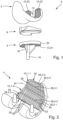
- Figure 1 shows an exploded view of an orthopedic knee joint prosthesis, designated overall with the reference number 2, with a femoral implant part 4, a tiboral implant part 6 and a meniscus replacement part 8, which can typically be anchored to the tiboral implant part 6.
- the femoral implant part 4 comprises a surface area 10 facing a bone of the thigh (femur) (not shown) and in contact with the bone.
- the tiboral implant part 6 also has a surface area 12 facing the bone of the lower leg (tibia) and in contact with the bone.
- the femoral implant part 4 has at least one dome- or shaft-shaped projection 14 and the tiboral implant part 6 has an elongated projection 16, each of which serves for engagement and anchoring on the femur or lower leg bone.
- the projection 16 of the tiboral implant part 6 is also connected to a disk-shaped plateau part 20 of the tiboral implant part 6 via cheek-shaped or wing-shaped sections 18 extending in the vertical plane.
- the femoral implant part 4 as well as the tiboral implant part 6 are each formed with a three-dimensional surface structure 22 or 24 in the area of their bone contact, namely surface area 10, 12.
- this three-dimensional surface structure 22, 24 protrudes macroscopically over at least 0.5 mm and in particular up to 3 mm from a Surface of the respective surface area 10, 12 of the respective implant part 4 or 6.
- the three-dimensional surface structure 24 of the tiboral implant part 6 can be designed in a correspondingly analogous manner.
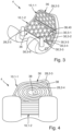
- Fig. 2 shows a femoral implant part 4.
- the femoral implant part 4 comprises several surface areas 10 in contact with the bone, in which a three-dimensional surface structure 14 is formed.
- the surface areas 10-1 and 10-2 are considered.
- Other surface areas for example in the area of the femoral condyles, cannot be seen due to the view shown.
- Three-dimensional surface structures (not shown) can also be formed on the other surface areas.
- a respective surface structure 14 of the surface areas 10-1 and 10-2 comprises a rib structure 26.
- a rib structure comprises ribs 28 or rib sections 30.
- a rib 28 is understood to be, for example, a web-shaped structure that runs without interruption and is curved out from the surface.
- a rib section 30 is, for example, any section of such a rib 28.
- a rib section 30 is a section that runs from an intersection 32, at which at least two ribs 18 cross or meet, to a further intersection 32.
- the rib structure 26 of the surface areas 10-1 and 10-2 comprises ribs 28-1 running longitudinally to a reference axis 34 and ribs 28-2 running transversely to the reference axis 34. Both surface areas 10-1 and 10-2 are completely surrounded in a respective edge area 36 by a circumferential rib 28-3.
- ribs 28 or rib sections 30 can also run obliquely to the reference axis 34.
- intersections 22 In the example shown according to Fig. 2 Longitudinal and transverse ribs 28-1, 28-2 meet at intersections 22 at a right angle. The intersections shown are therefore in the form of a + intersection. Alternatively, ribs 28 can also cross or meet at any other angle or in a different number. Other possible intersection shapes are, for example, T-intersections, Y-intersections, star intersections or any other intersection shapes.
- a plurality of intermediate spaces 38 are formed between at least ribs 28, 28-1, 28-2, 28-3 or rib sections 30 of the rib structure 26.
- a respective intermediate space 38 is delimited on the one hand by the surface of the surface region 10, 10-1, 10-2 and on a respective side by the ribs 28, 28-1, 28-2, 28-3 or rib sections 30.
- a respective intermediate space 38 is open on a side facing the bone in the implanted state.
- Fig. 3 shows a further embodiment.
- the surface areas 10-1 and 10-2 are considered.
- a respective surface structure 14 of the surface areas 10-1 and 10-2 comprises a rib structure 26.
- the surface structure 14 comprises ribs 28 or rib sections 30 which are arranged in a honeycomb pattern.
- six rib sections 30-1, 30-2, 30-3, 30-4, 30-5, 30-6 delimit a respective cell 40 of the honeycomb pattern.
- Each cell 40 of the honeycomb pattern forms a respective intermediate space 38.
- Fig. 4 shows a further embodiment.
- the surface areas 10-1 and 10-2 are considered.
- a respective surface structure 14 of the surface areas 10-1 and 10-2 comprises a rib structure 26.
- the rib structure 26 of the surface region 10-1 comprises a rib 28-4 with a spiral course.
- the rib 28-4 comprises several rib sections 30 which, due to the spiral course in the plane, run at least in sections in different directions from one another.
- the surface region 10-1 is completely surrounded in an edge region 36 by a circumferential rib 28-3.
- the rib structure 26 of the surface region 10-1 comprises a plurality of ribs 28-1 extending longitudinally to a reference axis 34.
- the surface region 10-2 is also completely surrounded by a circumferential rib 28-3 in an edge region 36.
- a combination of the illustrated or other three-dimensional surface structures in different surface areas is possible for a femoral implant 4.
- a combination within a respective surface area is also possible.
- a respective surface structure or a respective arrangement of the ribs or rib sections or a respective pattern does not necessarily have to extend over an entire surface area in a respective surface area.
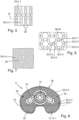
- Fig. 8 shows a tiboral implant 8 in a view from below of the surface area 12 in contact with the bone in the implanted state.
- the tiboral implant 8 comprises a continuous surface area 12.
- the surface area 12 can also be divided into several individual surface areas 12.
- the surface area 12 can comprise a surface structure which is analogous to the Fig. 2 to 7 illustrated or other three-dimensional surface structures.
- the surface structure comprises a rib structure 26, with ribs 28, 28-1, 28-2 and rib sections 30, which run obliquely with respect to a reference axis 34.
- a complete border is provided by a circumferential rib 28-3.
Landscapes
- Health & Medical Sciences (AREA)
- Orthopedic Medicine & Surgery (AREA)
- Engineering & Computer Science (AREA)
- Heart & Thoracic Surgery (AREA)
- Life Sciences & Earth Sciences (AREA)
- Transplantation (AREA)
- Cardiology (AREA)
- Biomedical Technology (AREA)
- Veterinary Medicine (AREA)
- Vascular Medicine (AREA)
- Oral & Maxillofacial Surgery (AREA)
- Animal Behavior & Ethology (AREA)
- General Health & Medical Sciences (AREA)
- Public Health (AREA)
- Physical Education & Sports Medicine (AREA)
- Manufacturing & Machinery (AREA)
- Prostheses (AREA)
Abstract
Description
- Die Erfindung betrifft ein femorales Implantatteil für eine orthopädische Kniegelenkprothese, wobei das femorale Implantatteil wenigstens einen einem Knochen zugewandten und im implantierten Zustand mit dem Knochen in Kontakt stehenden Oberflächenbereich aufweist. Die Erfindung betrifft auch ein tiborales Implantatteil für eine orthopädische Kniegelenkprothese, und eine orthopädische Kniegelenkprothese, sowie ein Herstellungsverfahren zum Herstellen der Implantatteile bzw. der orthopädischen Kniegelenkprothese.
- Femorale und tiborale Implantatteile und derartige Kniegelenkprothesen sind aus dem Stand der Technik bekannt. Für solche Implantate verwendeten Materialien bestehen im Wesentlichen aus Kobalt-Chrom bzw. Kobalt-Chrom -MolybdänLegierungen (Co-Cr-Mo) oder keramischen Werkstoffen. Die Prothese wird in der Regel mit Knochenzement am Knochen oder durch Einwachsen von Knochen direkt am Knochen befestigt.
- Metall- oder Keramikmaterialien verursachen einige unerwünschte klinische Probleme. Aufgrund der vergleichsweise guten Festigkeit und Stabilität und der guten biologischen Verträglichkeit von Polyetheretherketon (PEEK) Polymerwerkstoffen, ist es beispielsweise auch bekannt, Implantate aus Polyetheretherketon (PEEK) Polymerwerkstoffen herzustellen.
- Aufgrund der vergleichsweise hohen Stoßbelastung, der sehr komplexen Oberflächenform des Kniegelenks und des relativ geringen Anpassungsgrads ist der Druck auf die Oberfläche des Kniegelenks (10 bis 20 MPa) vergleichsweise hoch, beispielswiese viel höher als in einem Hüftgelenk (2 bis 5 MPa). Diese relativ hohen mechanischen Umgebungsbedingungen und Anforderungen führen zu einem erheblichen Verschleiß eines solchen Implantats.
- Der vorliegenden Erfindung liegt die Aufgabe zugrunde, ein femorales Implantatteil für eine orthopädische Kniegelenkprothese bzw. eine orthopädische Kniegelenkprothese bereitzustellen, mit der die genannten Nachteile überwunden werden können.
- Diese Aufgabe wird gelöst durch ein femorales Implantatteil gemäß Anspruch 1.
- Eine Ausführungsform betrifft ein femorales Implantatteil für eine orthopädische Kniegelenkprothese, wobei das femorale Implantatteil wenigstens einen dem Knochen zugewandten und im implantierten Zustand mit dem Knochen in Kontakt stehenden Oberflächenbereich aufweist, wobei das femorale Implantatteil wenigstens teilweise, zumindest der mit dem Knochen in Kontakt stehende Oberflächenbereich, aus einem Kunststoff, insbesondere PolyArylEtherKetone, (PAEK), insbesondere Polyetheretherketon (PEEK) oder Polyetheretherketon, (PEEK),-Verbundwerkstoff, gefertigt ist, und wobei das femorale Implantatteil eine dreidimensionale Oberflächenstruktur bei dem dem Knochen zugewandten Oberflächenbereich aufweist, und die dreidimensionale Oberflächenstruktur wenigstens eine Rippenstruktur umfasst, wobei wenigstens ein sich auf einer Oberfläche des Oberflächenbereichs in einer Ebene erstreckender erster Rippenabschnitt oder eine sich auf der Oberfläche des Oberflächenbereichs in der Ebene erstreckende erste Rippe der Rippenstruktur und ein sich auf der Oberfläche des Oberflächenbereichs in der Ebene erstreckender zweiter Rippenabschnitt oder eine sich auf der Oberfläche des Oberflächenbereichs in der Ebene erstreckende zweite Rippe der Rippenstruktur in der Ebene zumindest abschnittsweise in voneinander verschiedene Richtungen verlaufen.
- Die Rippenstruktur ist also auf einer Oberfläche des Oberflächenbereichs ausgebildet, und bildet so die dreidimensionale Oberflächenstruktur. Die Rippenstruktur umfasst wenigstens zwei oder mehr Rippen und/oder wenigstens zwei oder mehr Rippenabschnitte. Diese Rippen bzw. Rippenabschnitte sind auf der Oberfläche des Oberflächenbereichs angeordnet bzw. darauf ausgebildet. Die Rippen bzw. Rippenabschnitte ragen somit ausgehend von der Oberfläche des Oberflächenbereichs davon ab bzw. stehen ausgehend von der Oberfläche hervor. Unter einer Rippenstruktur wird eine ausgehend von der Oberfläche des Oberflächenbereichs ausgewölbte stegförmige Struktur verstanden.
- Die Rippen bzw. Rippenabschnitte ragen makroskopisch über wenigstens 0,5 mm und insbesondere bis 3 mm von einer Oberfläche des jeweiligen Oberflächenbereichs des Implantatteils hervor. In der Ebene, in der sich die Rippen bzw. Rippenabschnitte erstrecken, weisen diese eine Breite von wenigstens 0,5 mm und insbesondere bis 3 mm auf. Die Rippen bzw. Rippenabschnitte weisen in der Ebene eine beliebige Länge, insbesondere von wenigstens 1 mm auf. Eine maximale Länge wird beispielsweise durch eine konkrete Anordnung mehrerer Rippen bzw. Rippenabschnitte und/oder durch eine Erstreckung des Oberflächenbereichs begrenzt.
- Zwei Rippenabschnitte könne einer gemeinsamen Rippe oder zwei verschiedenen Rippen zugeordnet sein. Eine jeweilige Rippe und auch ein jeweiliger Rippenabschnitt können an sich in der Ebene beliebig verlaufen, insbesondere geradlinig aber auch abgewinkelt oder gekrümmt.
- Die auf der Oberfläche vorgesehene Rippenstruktur erhöht die Stabilität des femoralen Implantats. Die Verbesserung der Stabilität ist deswegen vorteilhaft, da ein Implantat aus Kunststoff, insbesondere Polyetheretherketon (PEEK) oder Polyetheretherketon, (PEEK),-Verbundwerkstoff, geringere Festigkeitswerte aufweist als ein vergleichbares Implantat aus Metall, beispielsweise aus einer Kobalt-Chrom-Legierung.
- Grundsätzlich kann das femorale Implantatteil zementfrei oder unter Verwendung von Knochenzement mit dem Knochen verankert werden.
- Zudem kann die vorgesehene Rippenstruktur vorteilhaft sein, um eine zementierte Verankerung des Implantats mit dem Knochen zu verbessern.
- Es ist beispielsweise vorgesehen, dass die dreidimensionale Oberflächenstruktur wenigstens einen, vorteilhafterweise mehrere, zwischen wenigstens zwei Rippen und/oder Rippenabschnitten der Rippenstruktur ausgebildeten Zwischenraum umfasst. Ein jeweiliger Zwischenraum wird einerseits begrenzt durch die Oberfläche des Oberflächenbereichs und zu einer jeweiligen Seite hin durch die Rippen bzw. Rippenabschnitte. Auf einer im implantierten Zustand dem Knochen zugewandten Seite ist ein jeweiliger Zwischenraum offen, und bildet so für eine zementierte Verankerung des Implantats einen Raum zum Aufnehmen des Zements.
- Gemäß einer Ausführungsform ist vorgesehen, dass eine jeweilige Rippe oder ein jeweiliger Rippenabschnitt in der Ebene in Bezug auf eine in der Ebene verlaufenden Bezugsachse längs zu der Bezugsachse, oder quer zu der Bezugsachse oder schräg, insbesondere in einem Winkel größer 0° und kleiner 180°, zu der Bezugsachse oder gekrümmt oder abgewinkelt verläuft.
- Gemäß einer Ausführungsform ist vorgesehen, dass wenigstens zwei oder mehr Rippen oder wenigstens zwei oder mehr Rippenabschnitte der Rippenstruktur wenigstens eine Kreuzung, insbesondere in Form einer T-Kreuzung, Y-Kreuzung, +-Kreuzung, Sternkreuzung, ausbilden. Solche Kreuzungen können die Stabilität bzw. Festigkeit der Rippenstruktur erhöhen und damit die Festigkeit des femoralen Implantats verbessern.
- Gemäß einer Ausführungsform ist vorgesehen, dass Rippen oder Rippenabschnitte der Rippenstruktur nach einem wabenförmigen Muster angeordnet sind, sodass jeweils sechs Rippen oder Rippenabschnitte eine jeweilige Zelle des wabenförmigen Musters begrenzen. Bei einer gleichmäßigen Wabenform treffen die jeweiligen Rippen oder Rippenabschnitte einer jeweiligen Zelle in einem Winkel von 120° aufeinander. Es sind auch Abweichungen von einer idealen Wabenform denkbar. Alternativ kann auch ein einem wabenförmigen Muster ähnliches Musters ausgebildet werden, beispielsweise können die Zellen auch durch ein Dreieck oder Fünfeck, als durch jeweils drei oder fünf Rippen oder Rippenabschnitte, bzw. sieben oder mehr Rippen oder Rippenabschnitte begrenzt sein. Eine Rippenstruktur, die nach einem solchen Muster, insbesondere einem wabenförmigen Muster ausgebildet ist, weist eine besonders vorteilhafte Festigkeit bzw. Stabilität auf.
- Gemäß einer Ausführungsform ist vorgesehen, dass eine jeweilige Rippe oder ein jeweiliger Rippenabschnitt einen in der Ebene spiralförmigen Verlauf umfasst. In diesem Zusammenhang kann es vorteilhaft sein, wenn der Oberflächenbereich in einem Randbereich durch eine oder mehrere Rippen oder Rippenabschnitt vollständig umrandet wird. Auf diese Weise wird ein Raum zum Aufnehmen von Zement bereitgestellt.
- Die eingangs genannte Aufgabe wird auch gelöst durch tiborales Implantatteil für eine orthopädische Kniegelenkprothese nach Anspruch 7. Das tiborale Implantatteil weist wenigstens einen dem Knochen zugewandten und im implantierten Zustand mit dem Knochen in Kontakt stehenden Oberflächenbereich auf. Das tiborale Implantatteil ist wenigstens teilweise, zumindest der mit dem Knochen in Kontakt stehende Oberflächenbereich, aus einem Kunststoff, insbesondere Polyetheretherketon (PEEK) oder Polyetheretherketon, (PEEK),-Verbundwerkstoff, gefertigt. Das tiborale Implantatteil weist eine dreidimensionale Oberflächenstruktur bei dem dem Knochen zugewandten Oberflächenbereich auf, und die dreidimensionale Oberflächenstruktur umfasst wenigstens eine Rippenstruktur, wobei wenigstens ein sich auf einer Oberfläche des Oberflächenbereichs in einer Ebene erstreckender erster Rippenabschnitt oder eine sich auf der Oberfläche des Oberflächenbereichs in der Ebene erstreckende erste Rippe der Rippenstruktur und ein sich auf der Oberfläche des Oberflächenbereichs in der Ebene erstreckender zweiter Rippenabschnitt oder eine sich auf der Oberfläche des Oberflächenbereichs in der Ebene erstreckende zweite Rippe der Rippenstruktur in der Ebene zumindest abschnittsweise in voneinander verschiedene Richtungen verlaufen.
- Gemäß weiteren Ausführungsformen ist das tiborale Implantatteil, beziehungsweise der Oberflächenbereich des tiboralen Implantatteils analog zu dem in Bezug auf das femorale Implantatteil beschriebenen Oberflächenbereich ausgebildet.
- Es ist beispielsweise vorgesehen, dass die dreidimensionale Oberflächenstruktur wenigstens einen, vorteilhafterweise mehrere, zwischen wenigstens zwei Rippen und/oder Rippenabschnitten der Rippenstruktur ausgebildeten Zwischenraum umfasst.
- Gemäß einer Ausführungsform ist vorgesehen, dass eine jeweilige Rippe oder ein jeweiliger Rippenabschnitt in der Ebene in Bezug auf eine in der Ebene verlaufenden Bezugsachse längs zu der Bezugsachse, oder quer zu der Bezugsachse oder schräg, insbesondere in einem Winkel größer 0° und kleiner 180°, zu der Bezugsachse oder gekrümmt oder abgewinkelt verläuft.
- Gemäß einer Ausführungsform ist vorgesehen, dass wenigstens zwei oder mehr Rippen oder wenigstens zwei oder mehr Rippenabschnitte der Rippenstruktur wenigstens eine Kreuzung, insbesondere eine T-Kreuzung, Y-Kreuzung, +-Kreuzung, Sternkreuzung, ausbilden.
- Gemäß einer Ausführungsform ist vorgesehen, dass Rippen oder Rippenabschnitte der Rippenstruktur nach einem wabenförmigen Muster angeordnet sind, sodass jeweils sechs Rippen oder Rippenabschnitte eine jeweilige Zelle des wabenförmigen Musters begrenzen.
- Gemäß einer Ausführungsform ist vorgesehen, dass eine jeweilige Rippe oder ein jeweiliger Rippenabschnitt einen in der Ebene spiralförmigen Verlauf umfasst. In diesem Zusammenhang kann es vorteilhaft sein, wenn der Oberflächenbereich in einem Randbereich durch eine oder mehrere Rippen oder Rippenabschnitt vollständig umrandet wird. Die eingangs genannte Aufgabe wird auch gelöst durch eine orthopädische Kniegelenkprothese nach Anspruch 9. Eine solche orthopädische Kniegelenkprothese umfasst ein femorales Implantatteil gemäß den beschriebenen Ausführungsformen und/oder ein tiborales Implantatteil gemäß den beschriebenen Ausführungsformen, und gegebenenfalls ein Meniskus-Ersatzteil, welches einen Gleitpartner für das femorale Implantatteil bildet und an dem tiboralen Implantatteil gehalten ist.
- Weitere Ausführungsformen betreffen ein Verfahren zur Herstellung eines femoralen Implantatteils gemäß den beschriebenen Ausführungsformen und/oder eines tiboralen Implantatteils gemäß den beschriebenen Ausführungsformen. Es ist beispielsweise vorgesehen, dass das femorale Implantatteil und/oder das tiborale Implantatteil in einem Spritzgussverfahren oder in einem additiven Fertigungsverfahren hergestellt wird. Bei einem Spritzgussverfahren wird die dreidimensionalen Oberflächenstruktur durch Einspritzen von Material in einen entsprechenden Formhohlraum hergestellt. Bei einem additiven Fertigungsverfahren, 3D-Druck wird die dreidimensionalen Oberflächenstruktur durch schichtweises Hinzufügen von Material auf die Oberfläche hergestellt.
- Weitere Merkmale, Einzelheiten und Vorteile der Erfindung ergeben sich aus den beigefügten Patentansprüchen und aus der zeichnerischen Darstellung und nachfolgenden Beschreibung einer erfindungsgemäßen Ausführungsform der orthopädischen Kniegelenksprothese. Dabei bezeichnen gleiche Bezugszeichen in verschiedenen Figuren jeweils gleiche oder zumindest ihrer Funktion nach vergleichbare Elemente. Bei der Beschreibung einzelner Figuren wird gegebenenfalls auch auf Elemente aus anderen Figuren Bezug genommen.
- In der Zeichnung zeigt:
- Fig. 1
- eine explosionsartige Darstellung einer erfindungsgemäßen Ausführungsform einer orthopädischen Kniegelenksprothese mit einem femoralen Implantatteil, einem tiboralen Implantatteil und einem an dem tiboralen Implantatteil festlegbaren Meniskus-Ersatzteil;
- Fig. 2
- eine Ansicht eines femoralen Implantatteils für eine orthopädische Kniegelenksprothese gemäß einer ersten Ausführungsform;
- Fig. 3
- eine Ansicht eines femoralen Implantatteils für eine orthopädische Kniegelenksprothese gemäß einer weiteren Ausführungsform;
- Fig. 4
- eine Ansicht eines femoralen Implantatteils für eine orthopädische Kniegelenksprothese gemäß einer weiteren Ausführungsform;
- Fig. 5
- eine Ansicht einer dreidimensionalen Oberflächenstruktur gemäß einer ersten Ausführungsform;
- Fig. 6
- eine Ansicht einer dreidimensionalen Oberflächenstruktur gemäß einer weiteren Ausführungsform;
- Fig. 7
- eine Ansicht einer dreidimensionalen Oberflächenstruktur gemäß einer weiteren Ausführungsform;
- Fig. 8
- eine Ansicht eines tiboralen Implantatteils in Draufsicht von unten.
-
Figur 1 zeigt in explosionsartiger Darstellung eine insgesamt mit dem Bezugszeichen 2 bezeichnete orthopädische Kniegelenkprothese mit einem femoralen Implantatteil 4, einem tiboralen Implantatteil 6 und einem Meniskus-Ersatzteil 8, welches typischerweise an dem tiboralen Implantatteil 6 verankerbar ist. Das femorale Implantatteil 4 umfasst einen einem nicht dargestellten Knochen des Oberschenkels (Femur) zugewandten und mit dem Knochen in Kontakt stehenden Oberflächenbereich 10. - Das tiborale Implantatteil 6 weist ebenfalls einen dem Knochen des Unterschenkels (Tibia) zugewandten und mit dem Knochen in Kontakt stehenden Oberflächenbereich 12 auf.
- Das femorale Implantatteil 4 weist zumindest einen dom- oder schaftförmigen Vorsprung 14 und das tiborale Implantatteil 6 einen langgestreckten Vorsprung 16 auf, die jeweils zum Eingriff und zur Verankerung an dem Oberschenkel- bzw. Unterschenkelknochen dienen. Der Vorsprung 16 des tiboralen Implantatteils 6 ist zudem über in der Vertikalebene erstreckte wangenförmige bzw. flügelförmige Abschnitte 18 an einem scheibenförmigen Plateauteil 20 des tiboralen Implantatteils 6 angebunden.
- Im beispielhaft und bevorzugt dargestellten Fall ist das femorale Implantatteil 4 wie auch das tiborale Implantatteil 6 im Bereich ihres Knochenkontakts, nämlich Oberflächenbereich 10, 12 jeweils mit einer dreidimensionalen Oberflächenstruktur 22 bzw. 24 ausgebildet. In beiden Fällen ragt diese dreidimensionale Oberflächenstruktur 22, 24 makroskopisch über wenigstens 0,5 mm und insbesondere bis 3 mm von einer Oberfläche des jeweiligen Oberflächenbereich 10, 12 des jeweilige Implantatteil 4 bzw. 6 hervor.
- Unter Bezugnahme auf die
Figuren 2 bis 7 werden am Beispiel des femoralen Implantatteils 4 im Folgenden verschiedene vorteilhafte Ausführungsformen der dreidimensionalen Oberflächenstruktur 22 erläutert. Die dreidimensionale Oberflächenstruktur 24 des tiboralen Implantatteils 6 kann entsprechend analog ausgebildet sein. -
Fig. 2 zeigt ein femorales Implantatteil 4. Im Beispiel umfasst das femorale Implantatteil 4 mehrere mit dem Knochen in Kontakt stehenden Oberflächenbereiche 10 bei denen eine dreidimensionalen Oberflächenstruktur 14 ausgebildet ist. Im Beispiel werden die Oberflächenbereiche 10-1, und 10-2 betrachtet. Weitere Oberflächenbereiche, beispielsweise im Bereich der Femurkondylen, sind aufgrund der dargestellten Ansicht, nicht einsehbar. Auf den weiteren Oberflächenbereichen können auch dreidimensionale Oberflächenstrukturen (nicht dargestellt) ausgebildet sein. - Eine jeweilige Oberflächenstruktur 14 der Oberflächenbereiche 10-1, und 10-2 umfasst eine Rippenstruktur 26. Eine solche Rippenstruktur umfasst Rippen 28 bzw. Rippenabschnitte 30. Unter einer Rippe 28 wird beispielsweise eine ohne Unterbrechung verlaufende, ausgehend von der Oberfläche ausgewölbte stegförmige Struktur, verstanden. Ein Rippenabschnitt 30 ist beispielsweise ein beliebiger Abschnitt einer solchen Rippe 28. Insbesondere ist ein Rippenabschnitt 30 ein von einer Kreuzung 32, an der sich wenigstens zwei Rippen 18 kreuzen bzw., aufeinandertreffen, bis zu einer weiteren Kreuzung 32 verlaufender Abschnitt.
- In der Ausführungsform gemäß
Fig. 2 umfasst die Rippenstruktur 26 der Oberflächenbereiche 10-1, und 10-2 längs zu einer Bezugsachse 34 verlaufende Rippen 28-1, und quer zu der Bezugsachse 34 verlaufende Rippen 28-2. Beide Oberflächenbereiche 10-1, und 10-2 werden in einem jeweiligen Randbereich 36 durch eine umlaufende Rippe 28-3 vollständig umrandet. - Alternativ können Rippen 28 bzw. Rippenabschnitte 30 auch schräg zu der Bezugsachse 34 verlaufen.
- Im dargestellten Beispiel gemäß
Fig. 2 treffen längs und quer verlaufende Rippen 28-1, 28-2 an Kreuzungen 22 in einem rechten Winkel aufeinander. Die dargestellten Kreuzungen sind daher von der Form einer +-Kreuzung. Alternativ können Rippen 28 auch in beliebigen anderen Winkeln oder in einer anderen Anzahl sich kreuzen bzw. aufeinandertreffen. Weiter mögliche Kreuzungsformen sind beispielsweise T-Kreuzung, Y-Kreuzung, Sternkreuzung oder beliebig andere Kreuzungsformen. - Im dargestellten Beispiel gemäß
Fig. 2 sind zwischen wenigstens Rippen 28, 28-1, 28-2, 28-3 bzw. Rippenabschnitten 30 der Rippenstruktur 26 mehrere Zwischenräume 38 ausgebildet. Ein jeweiliger Zwischenraum 38 wird einerseits begrenzt durch die Oberfläche des Oberflächenbereichs 10, 10-1, 10-2 und zu einer jeweiligen Seite hin durch die Rippen 28, 28-1, 28-2, 28-3 bzw. Rippenabschnitte 30. Auf einer im implantierten Zustand dem Knochen zugewandten Seite ist ein jeweiliger Zwischenraum 38 offen. -
Fig. 3 zeigt eine weitere Ausführungsform. Im Beispiel werden die Oberflächenbereiche 10-1, und 10-2 betrachtet. Eine jeweilige Oberflächenstruktur 14 der Oberflächenbereiche 10-1, und 10-2 umfasst eine Rippenstruktur 26. Die Oberflächenstruktur 14 umfasst Rippen 28, bzw. Rippenabschnitte 30, die nach einem wabenförmigen Muster angeordnet sind. Im Beispiel begrenzen sechs Rippenabschnitte 30-1, 30-2, 30-3, 30-4, 30-5, 30-6 eine jeweilige Zelle 40 des wabenförmigen Musters. - Eine jeweilige Zelle 40 des wabenförmigen Musters bildet einen jeweiligen Zwischenraum 38.
-
Fig. 4 zeigt eine weitere Ausführungsform. Im Beispiel werden die Oberflächenbereiche 10-1, und 10-2 betrachtet. Eine jeweilige Oberflächenstruktur 14 der Oberflächenbereiche 10-1, und 10-2 umfasst eine Rippenstruktur 26. - Die Rippenstruktur 26 des Oberflächenbereichs 10-1 umfasst eine Rippe 28-4 mit einem spiralförmigen Verlauf. Die Rippe 28-4 umfasst mehrere Rippenabschnitte 30, die aufgrund des spiralförmigen Verlaufs in der Ebene zumindest abschnittsweise in voneinander verschiedene Richtungen verlaufen. Der Oberflächenbereich 10-1 wird in einem Randbereich 36 durch eine umlaufende Rippe 28-3 vollständig umrandet.
- Die Rippenstruktur 26 des Oberflächenbereichs 10-1 umfasst mehrere längs zu einer Bezugsachse 34 verlaufende Rippen 28-1.
- Der Oberflächenbereich 10-2 wird in einem Randbereich 36 ebenfalls durch eine umlaufende Rippe 28-3 vollständig umrandet.
- In den
Figuren 5, 6, 7 sind Ausschnitte der dreidimensionalen Oberflächenstrukturen ausFiguren 2 ,3, 4 dargestellt. - Grundsätzlich sind bei einem femoralen Implantat 4 Kombination der dargestellten oder auch weiteren dreidimensionalen Oberflächenstrukturen in verschiedenen Oberflächenbereich möglich. Es ist auch eine Kombination innerhalb eines jeweiligen Oberflächenbereichs möglich. Eine jeweilige Oberflächenstruktur bzw. eine jeweilige Anordnung der Rippen bzw. Rippenabschnitte bzw. ein jeweiliges Muster muss sich bei einem jeweiligen Oberflächenbereich nicht zwingend über einen gesamten Oberflächenbereich erstrecken.
-
Fig. 8 zeigt ein tiborales Implantat 8 in einer Ansicht von unten auf den im implantierten Zustand mit dem Knochen in Kontakt stehenden Oberflächenbereich 12. GemäßFig. 8 umfasst das tiborale Implantat 8 einen durchgehenden Oberflächenbereich 12. Der Oberflächenbereich 12 kann aber auch in mehrere einzelne Oberflächenbereiche 12 unterteilt sein. Der Oberflächenbereich 12 kann eine Oberflächenstruktur umfassen, die analog zu den inFig. 2 bis 7 dargestellten oder auch weiteren dreidimensionalen Oberflächenstrukturen ausgebildet ist. Im Beispiel umfasst die Oberflächenstruktur eine Rippenstruktur 26, mit Rippen 28, 28-1, 28-2 und Rippenabschnitten 30, die schräg in Bezug auf eine Bezugsachse 34 verlaufen. Weiter ist in einem Randbereich 36 eine vollständige Umrandung durch eine umlaufende Rippe 28-3 vorgesehen.
Claims (10)
- Femorales Implantatteil (4) für eine orthopädische Kniegelenkprothese (2), wobei das femorale Implantatteil (4) wenigstens einen dem Knochen zugewandten und im implantierten Zustand mit dem Knochen in Kontakt stehenden Oberflächenbereich (10) aufweist, wobei das femorale Implantatteil (4) wenigstens teilweise, zumindest der mit dem Knochen in Kontakt stehende Oberflächenbereich (10), aus einem Kunststoff, insbesondere Polyetheretherketon (PEEK) oder Polyetheretherketon, (PEEK),-Verbundwerkstoff, gefertigt ist, und wobei das femorale Implantatteil (4) eine dreidimensionale Oberflächenstruktur () bei dem dem Knochen zugewandten Oberflächenbereich (10) aufweist, und die dreidimensionale Oberflächenstruktur (14) wenigstens eine Rippenstruktur (26) umfasst, wobei wenigstens ein sich auf einer Oberfläche des Oberflächenbereichs (10) in einer Ebene erstreckender erster Rippenabschnitt (30) oder eine sich auf der Oberfläche des Oberflächenbereichs (10) in der Ebene erstreckende erste Rippe (28, 28-1) der Rippenstruktur (26) und ein sich auf der Oberfläche des Oberflächenbereichs (10) in der Ebene erstreckender zweiter Rippenabschnitt (30) oder eine sich auf der Oberfläche des Oberflächenbereichs (10) in der Ebene erstreckende zweite Rippe (28, 28-2) der Rippenstruktur (26) in der Ebene zumindest abschnittsweise in voneinander verschiedene Richtungen verlaufen.
- Femorales Implantatteil (4) nach Anspruch 1, wobei die dreidimensionale Oberflächenstruktur (14) wenigstens einen zwischen wenigstens zwei Rippen (28, 28-1, 28-2, 28-3) und/oder Rippenabschnitten (30) der Rippenstruktur (26) ausgebildeten Zwischenraum (38) umfasst.
- Femorales Implantatteil (4) nach einem der Ansprüche 1 oder 2, wobei eine jeweilige Rippe (28, 28-1, 28-2, 28-3) oder ein jeweiliger Rippenabschnitt (30) in der Ebene in Bezug auf eine in der Ebene verlaufenden Bezugsachse (34) längs zu der Bezugsachse (34), oder quer zu der Bezugsachse (34) oder schräg, insbesondere in einem Winkel größer 0° und kleiner 180°, zu der Bezugsachse (34) oder gekrümmt oder abgewinkelt verläuft.
- Femorales Implantatteil (4) nach einem der vorhergehenden Ansprüche, wobei wenigstens zwei oder mehr Rippen (28, 28-1, 28-2, 28-3) oder wenigstens zwei oder mehr Rippenabschnitte (30) der Rippenstruktur (26) wenigstens eine Kreuzung (32), insbesondere eine T-Kreuzung, Y-Kreuzung, +-Kreuzung, Sternkreuzung, ausbilden.
- Femorales Implantatteil (4) nach einem der vorhergehenden Ansprüche, wobei Rippen (28) oder Rippenabschnitte (30) der Rippenstruktur (28) nach einem wabenförmigen Muster angeordnet sind, sodass jeweils sechs Rippen (28) oder Rippenabschnitte (30, 30-1, 30-2, 30-3, 30-4, 30-5, 30-6) eine jeweilige Zelle (40) des wabenförmigen Musters begrenzen.
- Femorales Implantatteil (4) nach einem der vorhergehenden Ansprüche, wobei eine jeweilige Rippe (28, 28-4) oder ein jeweiliger Rippenabschnitt (30) einen in der Ebene spiralförmigen Verlauf umfasst.
- Tiborales Implantatteil (6) für eine orthopädische Kniegelenkprothese (2), wobei das tiborale Implantatteil (6) wenigstens einen dem Knochen zugewandten und im implantierten Zustand mit dem Knochen in Kontakt stehenden Oberflächenbereich (12) aufweist, wobei das tiborale Implantatteil (6) wenigstens teilweise, zumindest der mit dem Knochen in Kontakt stehende Oberflächenbereich (12), aus einem Kunststoff, insbesondere Polyetheretherketon (PEEK) oder Polyetheretherketon, (PEEK),-Verbundwerkstoff, gefertigt ist, und wobei das tiborale Implantatteil (6) eine dreidimensionale Oberflächenstruktur (16) bei dem dem Knochen zugewandten Oberflächenbereich (12) aufweist, und die dreidimensionale Oberflächenstruktur wenigstens eine Rippenstruktur (26) umfasst, wobei wenigstens ein sich auf einer Oberfläche des Oberflächenbereichs (12) in einer Ebene erstreckender erster Rippenabschnitt (30) oder eine sich auf der Oberfläche des Oberflächenbereichs (12) in der Ebene erstreckende erste Rippe (28, 28-1) der Rippenstruktur (26) und ein sich auf der Oberfläche des Oberflächenbereichs (12) in der Ebene erstreckender zweiter Rippenabschnitt (30) oder eine sich auf der Oberfläche des Oberflächenbereichs (12) in der Ebene erstreckende zweite Rippe (28, 28-2) der Rippenstruktur (26) in der Ebene zumindest abschnittsweise in voneinander verschiedene Richtungen verlaufen.
- Tiborales Implantatteil (6) nach Anspruch, wobei das tiborale Implantatteil (6) nach einem der Ansprüche 2 bis 6 ausgebildet ist.
- Orthopädische Kniegelenkprothese (2) umfassend ein femorales Implantatteil (4), nach einem der Ansprüche 1 bis 6, und/oder ein tiborales Implantatteil (6) nach einem der Ansprüche 7 oder 8, und gegebenenfalls und mit einem Meniskus-Ersatzteil (8), welches einen Gleitpartner für das femorale Implantatteil (4) bildet und an dem tiboralen Implantatteil (6) gehalten ist.
- Verfahren zur Herstellung eines femoralen Implantatteils (4) nach einem der Ansprüche 1 bis 6 und/oder eines tiboralen Implantatteils (6) nach einem der Ansprüche 7 oder 8, wobei das femorale Implantatteil (4) und/oder das tiborale Implantatteil (6) in einem Spritzgussverfahren oder in einem additiven Fertigungsverfahren hergestellt wird.
Applications Claiming Priority (1)
| Application Number | Priority Date | Filing Date | Title |
|---|---|---|---|
| DE102023118837.2A DE102023118837A1 (de) | 2023-07-17 | 2023-07-17 | Orthopädische Kniegelenkprothese |
Publications (1)
| Publication Number | Publication Date |
|---|---|
| EP4494609A1 true EP4494609A1 (de) | 2025-01-22 |
Family
ID=91829328
Family Applications (1)
| Application Number | Title | Priority Date | Filing Date |
|---|---|---|---|
| EP24186585.6A Pending EP4494609A1 (de) | 2023-07-17 | 2024-07-04 | Orthopädische kniegelenkprothese |
Country Status (4)
| Country | Link |
|---|---|
| US (1) | US20250025312A1 (de) |
| EP (1) | EP4494609A1 (de) |
| JP (1) | JP2025014107A (de) |
| DE (1) | DE102023118837A1 (de) |
Families Citing this family (1)
| Publication number | Priority date | Publication date | Assignee | Title |
|---|---|---|---|---|
| GB202112071D0 (en) * | 2021-08-23 | 2021-10-06 | Invibio Knees Ltd | Surgical implant |
Citations (5)
| Publication number | Priority date | Publication date | Assignee | Title |
|---|---|---|---|---|
| US20160235955A1 (en) * | 2015-02-16 | 2016-08-18 | Augusto Magagnoli | Spacer device for treatment of an infected seat of the human body |
| US9820858B2 (en) * | 2015-03-23 | 2017-11-21 | Modal Manufacturing, LLC | Knee implants and instruments |
| US20190029833A1 (en) * | 2016-03-02 | 2019-01-31 | Invibio Knees Limited | Prosthesis |
| US20200246151A1 (en) * | 2016-03-02 | 2020-08-06 | Invibio Knees Limited | Replacement knee component |
| US20220096242A1 (en) * | 2019-03-11 | 2022-03-31 | Yan Wang | Mts medial tibial plateau patch, modular mts medial tibial plateau patch and minimally invasive replacement method therefor |
Family Cites Families (1)
| Publication number | Priority date | Publication date | Assignee | Title |
|---|---|---|---|---|
| US3869731A (en) * | 1973-02-14 | 1975-03-11 | Univ California | Articulated two-part prosthesis replacing the knee joint |
-
2023
- 2023-07-17 DE DE102023118837.2A patent/DE102023118837A1/de active Pending
-
2024
- 2024-05-28 JP JP2024086214A patent/JP2025014107A/ja active Pending
- 2024-07-03 US US18/762,992 patent/US20250025312A1/en active Pending
- 2024-07-04 EP EP24186585.6A patent/EP4494609A1/de active Pending
Patent Citations (5)
| Publication number | Priority date | Publication date | Assignee | Title |
|---|---|---|---|---|
| US20160235955A1 (en) * | 2015-02-16 | 2016-08-18 | Augusto Magagnoli | Spacer device for treatment of an infected seat of the human body |
| US9820858B2 (en) * | 2015-03-23 | 2017-11-21 | Modal Manufacturing, LLC | Knee implants and instruments |
| US20190029833A1 (en) * | 2016-03-02 | 2019-01-31 | Invibio Knees Limited | Prosthesis |
| US20200246151A1 (en) * | 2016-03-02 | 2020-08-06 | Invibio Knees Limited | Replacement knee component |
| US20220096242A1 (en) * | 2019-03-11 | 2022-03-31 | Yan Wang | Mts medial tibial plateau patch, modular mts medial tibial plateau patch and minimally invasive replacement method therefor |
Also Published As
| Publication number | Publication date |
|---|---|
| US20250025312A1 (en) | 2025-01-23 |
| JP2025014107A (ja) | 2025-01-29 |
| DE102023118837A1 (de) | 2025-01-23 |
Similar Documents
| Publication | Publication Date | Title |
|---|---|---|
| DE69225472T2 (de) | Längliche hüftpfannenschale | |
| DE69105734T2 (de) | Poröse befestigungsfläche. | |
| EP0561263B1 (de) | Implantat als Knochenersatz | |
| DE69728001T2 (de) | Prothese mit veränderbarer Passungs- und Spannungsverteilung | |
| DE202006015416U1 (de) | Augmentationskomponente für Knochenimplantate | |
| EP2219562A1 (de) | Zwischenwirbelimplantat | |
| EP0159462B1 (de) | Femurale Totalendoprothese für ein Hüftgelenk | |
| EP0366603B1 (de) | Blattartiger Schaft aus Metall für eine Femurkopfprothese | |
| DE102009014184A1 (de) | Implantat zur Fusion von Wirbelsäulensegmenten | |
| EP2526900B1 (de) | Form zur Herstellung einer Femurkomponente eines Kniegelenkspacers | |
| EP0943297A1 (de) | Femorale Hüftgelenkprothese | |
| DE4038929A1 (de) | Implantat mit veraenderlichem elastizitaetsmodul | |
| EP0311749A1 (de) | Oberschenkelteil einer Hüftgelenkendoprothese | |
| DE3216539A1 (de) | Knochenenimplantat, insbesondere femorale hueftgelenkprothese | |
| WO2019052681A1 (de) | Zwischenwirbel-implantat | |
| EP1164978A2 (de) | Blattartiger schaft einer hüftgelenkprothese für die verankerung im femur | |
| EP1740129B1 (de) | Zwischenwirbelprothese oder bandscheibenprothese | |
| EP2532323A1 (de) | Form zur Herstellung einer Tibiakomponente eines Kniegelenkspacers | |
| DE102023118837A1 (de) | Orthopädische Kniegelenkprothese | |
| DE102011050183A1 (de) | Oberflächenprofilierter Gitterkörper | |
| EP3662868B1 (de) | Zwischenwirbelimplantat und verfahren zur herstellung eines zwischenwirbelimplantats | |
| DE102014114163A1 (de) | Implantat | |
| DE69834518T2 (de) | Knieprothese | |
| DE19740689A1 (de) | Oberschenkelprothese | |
| DE102023116397A1 (de) | Endoprothese mit verbesserter primärstabiltität und optimierten revisionseigenschaften |
Legal Events
| Date | Code | Title | Description |
|---|---|---|---|
| PUAI | Public reference made under article 153(3) epc to a published international application that has entered the european phase |
Free format text: ORIGINAL CODE: 0009012 |
|
| STAA | Information on the status of an ep patent application or granted ep patent |
Free format text: STATUS: THE APPLICATION HAS BEEN PUBLISHED |
|
| AK | Designated contracting states |
Kind code of ref document: A1 Designated state(s): AL AT BE BG CH CY CZ DE DK EE ES FI FR GB GR HR HU IE IS IT LI LT LU LV MC ME MK MT NL NO PL PT RO RS SE SI SK SM TR |
|
| STAA | Information on the status of an ep patent application or granted ep patent |
Free format text: STATUS: REQUEST FOR EXAMINATION WAS MADE |
|
| 17P | Request for examination filed |
Effective date: 20250722 |
|
| GRAP | Despatch of communication of intention to grant a patent |
Free format text: ORIGINAL CODE: EPIDOSNIGR1 |
|
| STAA | Information on the status of an ep patent application or granted ep patent |
Free format text: STATUS: GRANT OF PATENT IS INTENDED |
|
| INTG | Intention to grant announced |
Effective date: 20260330 |