EP4494578A1 - Electrosurgical generator for controlling an ultrasonic transducer of an electrosurgical instrument - Google Patents

Electrosurgical generator for controlling an ultrasonic transducer of an electrosurgical instrument Download PDF

Info

Publication number
EP4494578A1
EP4494578A1 EP24189201.7A EP24189201A EP4494578A1 EP 4494578 A1 EP4494578 A1 EP 4494578A1 EP 24189201 A EP24189201 A EP 24189201A EP 4494578 A1 EP4494578 A1 EP 4494578A1
Authority
EP
European Patent Office
Prior art keywords
signal
coefficients
transducer
frequency
calculated
Prior art date
Legal status (The legal status is an assumption and is not a legal conclusion. Google has not performed a legal analysis and makes no representation as to the accuracy of the status listed.)
Pending
Application number
EP24189201.7A
Other languages
German (de)
French (fr)
Inventor
Jelle Dijkstra
Thomas Fähsing
Current Assignee (The listed assignees may be inaccurate. Google has not performed a legal analysis and makes no representation or warranty as to the accuracy of the list.)
Olympus Winter and Ibe GmbH
Original Assignee
Olympus Winter and Ibe GmbH
Priority date (The priority date is an assumption and is not a legal conclusion. Google has not performed a legal analysis and makes no representation as to the accuracy of the date listed.)
Filing date
Publication date
Application filed by Olympus Winter and Ibe GmbH filed Critical Olympus Winter and Ibe GmbH
Publication of EP4494578A1 publication Critical patent/EP4494578A1/en
Pending legal-status Critical Current

Links

Images

Classifications

    • AHUMAN NECESSITIES
    • A61MEDICAL OR VETERINARY SCIENCE; HYGIENE
    • A61BDIAGNOSIS; SURGERY; IDENTIFICATION
    • A61B17/00Surgical instruments, devices or methods
    • A61B17/32Surgical cutting instruments
    • A61B17/320068Surgical cutting instruments using mechanical vibrations, e.g. ultrasonic
    • AHUMAN NECESSITIES
    • A61MEDICAL OR VETERINARY SCIENCE; HYGIENE
    • A61BDIAGNOSIS; SURGERY; IDENTIFICATION
    • A61B18/00Surgical instruments, devices or methods for transferring non-mechanical forms of energy to or from the body
    • A61B18/04Surgical instruments, devices or methods for transferring non-mechanical forms of energy to or from the body by heating
    • A61B18/12Surgical instruments, devices or methods for transferring non-mechanical forms of energy to or from the body by heating by passing a current through the tissue to be heated, e.g. high-frequency current
    • A61B18/14Probes or electrodes therefor
    • A61B18/1442Probes having pivoting end effectors, e.g. forceps
    • A61B18/1445Probes having pivoting end effectors, e.g. forceps at the distal end of a shaft, e.g. forceps or scissors at the end of a rigid rod
    • GPHYSICS
    • G16INFORMATION AND COMMUNICATION TECHNOLOGY [ICT] SPECIALLY ADAPTED FOR SPECIFIC APPLICATION FIELDS
    • G16HHEALTHCARE INFORMATICS, i.e. INFORMATION AND COMMUNICATION TECHNOLOGY [ICT] SPECIALLY ADAPTED FOR THE HANDLING OR PROCESSING OF MEDICAL OR HEALTHCARE DATA
    • G16H40/00ICT specially adapted for the management or administration of healthcare resources or facilities; ICT specially adapted for the management or operation of medical equipment or devices
    • G16H40/60ICT specially adapted for the management or administration of healthcare resources or facilities; ICT specially adapted for the management or operation of medical equipment or devices for the operation of medical equipment or devices
    • HELECTRICITY
    • H03ELECTRONIC CIRCUITRY
    • H03GCONTROL OF AMPLIFICATION
    • H03G3/00Gain control in amplifiers or frequency changers
    • H03G3/20Automatic control
    • H03G3/30Automatic control in amplifiers having semiconductor devices
    • H03G3/3005Automatic control in amplifiers having semiconductor devices in amplifiers suitable for low-frequencies, e.g. audio amplifiers
    • AHUMAN NECESSITIES
    • A61MEDICAL OR VETERINARY SCIENCE; HYGIENE
    • A61BDIAGNOSIS; SURGERY; IDENTIFICATION
    • A61B18/00Surgical instruments, devices or methods for transferring non-mechanical forms of energy to or from the body
    • A61B18/04Surgical instruments, devices or methods for transferring non-mechanical forms of energy to or from the body by heating
    • A61B18/12Surgical instruments, devices or methods for transferring non-mechanical forms of energy to or from the body by heating by passing a current through the tissue to be heated, e.g. high-frequency current
    • A61B18/1206Generators therefor
    • AHUMAN NECESSITIES
    • A61MEDICAL OR VETERINARY SCIENCE; HYGIENE
    • A61BDIAGNOSIS; SURGERY; IDENTIFICATION
    • A61B17/00Surgical instruments, devices or methods
    • A61B2017/00017Electrical control of surgical instruments
    • AHUMAN NECESSITIES
    • A61MEDICAL OR VETERINARY SCIENCE; HYGIENE
    • A61BDIAGNOSIS; SURGERY; IDENTIFICATION
    • A61B17/00Surgical instruments, devices or methods
    • A61B2017/00017Electrical control of surgical instruments
    • A61B2017/00132Setting operation time of a device
    • AHUMAN NECESSITIES
    • A61MEDICAL OR VETERINARY SCIENCE; HYGIENE
    • A61BDIAGNOSIS; SURGERY; IDENTIFICATION
    • A61B17/00Surgical instruments, devices or methods
    • A61B2017/00017Electrical control of surgical instruments
    • A61B2017/00137Details of operation mode
    • A61B2017/00141Details of operation mode continuous, e.g. wave

Definitions

  • the present invention is directed to a method for controlling an ultrasonic transducer of an electrosurgical instrument.
  • the invention is also directed to an electrosurgical generator for controlling an ultrasonic transducer of an electrosurgical instrument.
  • the invention is also directed to an electrosurgical installation comprising an electrosurgical generator and an ultrasonic transducer of an electrosurgical instrument connected to the electrosurgical generator.
  • Ultrasonic transducers are used to transform an alternating electrical signal into a mechanical oscillation of an electrosurgical instrument having an ultrasonic frequency.
  • the alternating electrical signal is basically stimulating the mechanical oscillation at a resonance frequency of the ultrasonic transducers.
  • Ultrasonic transducers can be modelled according to an equivalent circuit shown in Figure 3 .
  • the model shows a mechanical resonance circuit as an electrical equivalent (CM + LM + RM) and the parallel electrical capacitance (CE).
  • Ultrasonic transducers need to be driven at their mechanical resonance frequency. Since the resonance frequency changes with mechanical load, a control loop may be required to track the changing resonance frequency.
  • a PLL can be used to adjust the frequency according to the measured phase shift between the voltage across the transducer and the current of the electrical equivalent of the mechanical resonance circuit, which can be understood as the mechanical current. When the phase shift is positive, the resonance circuit is inductive, and the frequency is too high. When the phase shift is negative, the resonance circuit is capacitive, and the frequency is too low.
  • a possible control loop may contain analogue sensors, ADCs and a digital controller (FPGA) that drives the amplifier with a calculated frequency.
  • the controller may determine the phase shift between current and voltage by comparing their respective zero-crossings in the time domain.
  • an object of the present invention is to address at least one of the above-mentioned problems.
  • a solution shall be provided for improving the control of an ultrasonic transducer, in particular a solution shall be provided for identifying the mechanical resonance frequency of ultrasonic transducers in an improved manner and/or made more reliable.
  • At least a solution shall be suggested which is an alternative solution with respect to known solutions.
  • a method is suggested according to claim 1.
  • a method for controlling an ultrasonic transducer of an electrosurgical instrument is suggested.
  • Such ultrasonic transducer is driven by an alternating electrical overall current signal having a signal frequency.
  • Such transducer may be driven mainly by means of a current source having a voltage limit.
  • Such overall current signal is resulting in an alternating electrical instrument voltage signal of the transducer, depending on a mechanical oscillation of the transducer.
  • the alternating electrical overall current signal which can be a mainly sinusoidal current signal, is applied to the transducer.
  • the instrument voltage signal results.
  • the shape of the instrument voltage signal mainly depends on a mechanical oscillation of the transducer.
  • the instrument voltage signal has a transducer phase shift with respect to a main current component of the overall current signal depending on the mechanical oscillations of the transducer.
  • a resulting phase shift i.e. a phase shift between the instrument voltage signal and the main current component.
  • the ultrasonic transducer is having a fluctuating mechanical resonance frequency.
  • Such mechanical resonance frequency might be in a range of 45 kHz - 50 kHz, in particular in the area of 46 kHz - 49 kHz.
  • the resonance frequency may vary within this range. Of course it could also be outside of this range.
  • the mechanical resonance frequency is fluctuating, at least slightly, and that may depend on the use of the electrosurgical instrument. For example, the resonance frequency may be different depending on whether the electrosurgical instrument is in contact with tissue or not.
  • the transducer phase shift indicates if and possibly how well the mechanical resonance frequency is met by the voltage signal and current signal.
  • the resonance frequency is met, if there is no phase shift. Therefore, it is important to determine the transducer phase shift and adjust the signal frequency such that the amplitude of the phase shift decreases.
  • a positive phase shift indicates that the resonance circuit is inductive and the frequency is too high and thus shall be reduced.
  • the phase shift is negative, the resonance circuit is capacitive, the frequency is too low and should be increased.
  • the signal coefficients can be calculated characterizing the particular signal also with respect to their phase relationship with respect to the common reference signal and such phase relationship can also be denoted as phase angle. Accordingly, these signal coefficients also specify the phase angle of both signals and in this way the transducer phase shift can be calculated, in particular by subtracting the one phase angle from the other. In this way, the transducer phase shift can be calculated in an easy and reliable manner without comparing any signal waveforms of the measured signals. It can also be done without identifying a zero crossing, or other significant point of the two signals.
  • each signal may be measured for one period using 100 samples each, maybe more.
  • two coefficients of one sampled signal are calculated based on 100 samples.
  • the signal frequency is adjusted to match the mechanical resonance frequency or to get closer to it. Accordingly, the transducer phase shift is calculated and it indicates a deviation between the mechanical resonance frequency and the signal frequency. Therefore, the signal frequency is adjusted to match the mechanical resonance frequency, at least to better match the mechanical resonance frequency. It was found that it is not necessary to identify the mechanical resonance frequency, but only to identify whether the signal frequency deviates from it.
  • Raising or reducing the signal frequency to get closer to the resonance frequency can be done in different ways.
  • One possibility is to raise or reduce the signal frequency by a constant value.
  • Such discrete way is in fact almost a continuous approach as there is a high repetition frequency for performing such raising or reducing.
  • a difference between the signal frequency and the resonance frequency leads to a change, in particular small change of the signal frequency letting it get at least a little bit closer to the mechanical resonance frequency.
  • This step is continuously repeated including repeating the calculating of the transducer phase shift. Accordingly, such step of adjusting is repeated quite often and each time the signal frequency gets a little bit closer to the mechanical resonance frequency, until it is almost reached.
  • Another possibility is to use a feedback control loop having a PID, or PI-control. According to the integral part of the control, the signal frequency found will keep its value when the input is zero.
  • the feedback can be the calculated transducer phase shift or a calculated difference between the signal frequency and a calculated, at least roughly calculated, mechanical resonance frequency.
  • the input value tends to zero with the signal frequency matching the mechanical resonance frequency.
  • a proportional factor can be calculated or determined in a simulation or determined by measurements during a test operation, when the mechanical resonance frequency is measured or estimated.
  • the mechanical resonance frequency is not high and in particular below 10% of a mean mechanical resonance frequency, possibly even below 5% of such mean mechanical resonance frequency. Accordingly, it can be assumed that the calculated transducer phase shift is almost proportional to the difference between the mechanical resonance frequency and the signal frequency. Therefore, the mechanical resonance frequency can quite easily and quite precisely be calculated in this way.
  • the calculating of the signal coefficients is based on samples of the overall current signal and samples of the instrument voltage signal. In this way, these values can be sampled during a control cycle and each time new values can be calculated, a new transducer phase shift can be calculated and the signal frequency can be adapted accordingly.
  • the instrument voltage signal will be measured and the overall current signal may also be measured.
  • the overall current signal may also just be known as it is generated as part of this the method, in particular by an electrosurgical generator generating such current signal.
  • a control cycle can be implemented calculating the transducer phase shift for each sample time and thus also adjusting the signal frequency at each sample time.
  • the signal coefficients characterize the first harmonic of the corresponding signal.
  • two signal coefficients of the main current component characterize the first harmonic of the main current component
  • two coefficients of the instrument voltage signal characterize the first harmonic of the instrument voltage signal.
  • Such coefficients can be calculated in a quasi-continuous way using a fast Fourier transform.
  • This way of calculating the signal coefficients also uses samples of the corresponding signal, i.e. samples of the current signal and samples of the main voltage signal.
  • the signal frequency is well-known, as the overall current signal is generated and thus its frequency is known. Accordingly, the period of such alternating, i.e. mainly sinusoidal signal, is also well-known. Therefore, said formula for calculating the signal coefficients is applied to sampled signals of exactly one signal period leading to a quite precise result of calculating this first harmonic Fourier trigonometric coefficients a 1 and b 1 .
  • the underlying signal frequency is expected to be in the range of 40 kHz and 50 kHz. It may also be a bit higher or a bit lower. However, as the signal frequency is this high, the time needed to sample values of one signal period is in the range of approximately 20 ⁇ s. It was also found that taking samples over one signal period is enough as it is enough to change the frequency of the current signal per signal period.
  • the transducer phase shift is calculated as the difference of the absolute phase shifts of the main current component and the instrument voltage signal.
  • the transducer phase shift can be calculated in an easy way and the use of the trigonometric calculation atan2 can be avoided. It was found that the transducer phase shift, i.e. said corresponding phase shift angle, is expected to be quite small, i.e. much below 30°, that such approximation is feasible. It was also found that according to the suggested adjusting of the signal frequency towards the mechanical resonance frequency, it is possible by such control to take care of having a good match of the signal frequency to the mechanical resonance frequency and thus have a small transducer phase shift. Accordingly, the suggested approximation can be used.
  • calculating the transducer phase shift and/or adjusting the signal frequency to match the mechanical resonance frequency or to get closer to it is repeated regularly for tracking changes of the mechanical resonance frequency, and in particular the calculating or adjusting is repeated with a predetermined repetition frequency being at least one repetition per 10 signal periods, preferably at least one repetition per 2 signal periods, in particular one repetition per signal period.
  • the signal frequency can be controlled to be very close to the mechanical resonance frequency.
  • the mechanical resonance frequency may depend on the electrosurgical instrument being in touch with tissue or other material or not being in touch with any material. Accordingly, just a small movement of the electrosurgical instrument when in operation may change said situation and accordingly the mechanical resonance frequency may also change. However, repeating the calculating and/or adjusting with one repetition per signal period leads to a fast tracking of the changed situation, as the signal period is approximately in the range of 20 ⁇ s. Compared to that, a manual movement of the electrosurgical instrument when in operation can be quite slow when compared to said high repetition frequency.
  • the signal coefficients in particular the signal coefficients for each signal being the first harmonic Fourier trigonometric coefficients a 1 and b 1 , are used to calculate an rms-value of the current signal, in particular of the main current component, and/or an rms-value of the voltage signal and/or a real power value of both signals. Accordingly, each rms-value and/or the real power value of both signals is calculated based on the first harmonic of the current signal and/or the voltage signal.
  • the nominal frequency ⁇ 0 can be used for ⁇ . That is relevant for any formula discussed.
  • the overall current which is in particular the current that is measured, has a main current component and a capacitive current component.
  • the main current component and the capacitive current component as an additional component.
  • This capacitive current component depends on a capacitance of the transducer.
  • This capacitive current component is basically - simply speaking - not involved in driving the mechanical movement of the ultrasonic electrosurgical instrument.
  • the main current component is calculated by subtracting the capacitive current component from the overall current signal.
  • the overall current signal can be measured and thus the measured alternating electrical current signal can be used as the overall current signal.
  • the properties of this overall current signal might be well-known and these properties could be used instead of measuring the alternating electrical current signal, i.e. the overall current signal.
  • the capacitive current component can be calculated.
  • One way of doing this is to use the first harmonic Fourier trigonometric coefficients a 1 and b 1 . These can be calculated as explained above. In this way, basically only the first harmonic of the current signal is considered which is advantageous as basically only this first harmonic component influences the phase shift caused by the capacity.
  • using the first harmonic Fourier trigonometric coefficients is reliable and tolerant to noise and distortions on the signal. In particular, the given formula provides a simple way to calculate the capacitive current component.
  • the main current component driving the mechanical oscillation of the transducer and thus the electrosurgical instrument is not very dominant when the signal frequency is very different from the mechanical resonance frequency.
  • the capacity is basically the only characteristic of the transducer influencing the overall current signal that is driven through the transducer. Accordingly, the relationship between the overall current signal and the resulting instrument voltage signal gives a clear indication of the capacitance.
  • the measured voltage might have a very small amplitude in particular in view of noise which is often present on measured voltage signals.
  • the evaluation or calculation might lead to problems, such as stability problems if noise level is too high, in relation to the signal amplitude.
  • the virtual resistance can be chosen such, that the virtual voltage signal is only significant when the frequency is at or close to the resonance frequency. It is not significantly high, i.e. lower than the measured voltage signal, when the signal frequency deviates significantly from the resonance frequency.
  • the influence of the virtual resistance and/or the resulting virtual voltage can be neglected and accordingly the deviation from the resonance frequency can be detected with high precision enabling the operating point to move towards the resonance frequency.
  • the virtual voltage signal is chosen such, that its average rms-value is between 3 to 20 times, in particular 5 to 10 times the rms average value of the voltage signal at the resonance frequency. Based on known average values of the voltage at the resonance frequency and corresponding main current component, the virtual resistance can be calculated accordingly.
  • the virtual resistance may be in a range of about 100-200 Ohms. It could also be chosen based on experiences.
  • the modified voltage i.e. the modified voltage signal using the signal coefficients previously calculated for the voltage signal and for the main current signal using the formula, which is explained further below: u ′ t ⁇ a 1 , u + R virt a 1 , i ⁇ CE ⁇ ⁇ 0 ⁇ b 1 , u ⁇ cos ⁇ 0 t + b 1 , u + b 1 , i + CE ⁇ ⁇ 0 ⁇ a 1 , u sin ⁇ 0 t
  • an electrosurgical generator for controlling an ultrasonic transducer of an electrosurgical instrument adapted to execute a method according to any of the preceding aspects.
  • the electrosurgical generator may have any corresponding control unit such as a digital controller, e.g. an FPGA and an amplifier connected to the controller and driven by the controller.
  • the controller may provide a calculated frequency that will be submitted to the amplifier and the amplifier will then generate a corresponding current signal.
  • the controller determines the phase shift between current and voltage and will base on that determination control the amplifier.
  • any method according to the explained aspects can be implemented at least partially as a computer program on such controller.
  • the electrosurgical generator may also comprise current and voltage sensors for measuring an overall current signal generated by the amplifier and for measuring a resulting instrument voltage signal. Such sensors may particularly be connected to the controller and/or to the amplifier.
  • an electrosurgical installation comprising an electrosurgical generator as explained above and an electrosurgical instrument.
  • the electrosurgical instrument is connected to the electrosurgical generator and the electrosurgical instrument may have an ultrasonic transducer.
  • the amplifier of the electrosurgical generator is connected to the ultrasonic transducer and provides an overall current signal to the ultrasonic transducer.
  • Figure 1 shows an electrosurgical generator 100 to which an electrosurgical instrument 102 is connected operating on a tissue 104 just schematically illustrated.
  • the electrosurgical generator 100 comprises a frequency converter 106 which is controlled by a control device 108.
  • the frequency converter when in operation provides at its output 110 an overall current signal which is applied to the attached electrosurgical instrument 102, resulting in an instrument voltage.
  • the instrument voltage is a simplified term for the instrument voltage signal and is thus a synonym for it.
  • a voltage sensor 112 for measuring the voltage signal and a current sensor 114 for measuring the overall current signal. These sensors 112, 114 are connected to the control device 108 for further consideration.
  • the control device 108 calculates from the current sample values provided by the current sensor 114 signal coefficients. Based on that, the control device 108 controls the frequency converter 106. Accordingly, at the frequency converter output, the overall current signal is generated depending on the calculated coefficients.
  • the voltage sensor 112 and/or the current sensor 114 are connected to the frequency converter 106 directly. It is also possible that the control device 108 is part of the frequency converter 106.
  • Figure 2 shows a simplified control structure 200 for controlling an ultrasonic transducer of an electrosurgical instrument.
  • Figure 2 shows schematically such electrosurgical instrument 202 having an ultrasonic transducer.
  • the electrosurgical instrument 202 and thus its ultrasonic transducer is connected to an amplifier 204.
  • the amplifier 204 can be identical to the frequency converter 106 of Figure 1 , or similar, or can be part of such frequency converter.
  • the amplifier 204 provides an alternating electrical overall current i m which is thus driven into the ultrasonic transducer 206 of the electrosurgical instrument 202.
  • the overall current is a simplified term for the overall current signal and is thus a synonym for it.
  • Driving this overall current i m results in an instrument voltage u m .
  • the overall current i m and accordingly the instrument voltage u m have a signal frequency f.
  • the transducer 206 works best when this signal frequency f matches a mechanical resonance frequency of the transducer 206.
  • the overall current i m and the instrument voltage u m are measured with a voltage sensor 208 and a current sensor 210. Accordingly, the instrument voltage u m and the overall current i m are measured.
  • the overall current and its measured value are the same and that the instrument voltage and its measured value are also the same.
  • the measured instrument voltage u m is given to a voltage Fourier transform block 212 calculating the first harmonic Fourier trigonometric coefficients a 1,u and b 1,u of the voltage signal.
  • the measured overall current i m is given to a current Fourier transform block 214 calculating the first harmonic trigonometric coefficients a 1,i and b 1,i of the current signal.
  • the first Fourier trigonometric coefficients a 1,i and b 1,i of the measured overall current i m are representing the overall current i m .
  • a capacitive current component can be calculated using the first harmonic Fourier trigonometric coefficients a 1,u and b 1,u of the measured instrument voltage u m and using the known capacitance C of the ultrasonic transducer 206. If the ultrasonic transducer capacitance C is not known, it can be measured as explained above, but it could also be known.
  • a capacitance current component of the overall current i m can be calculated and subtracted from the overall current i m .
  • the modification block 216 therefore receives the first harmonic trigonometric coefficients a 1,u and b 1,u of the measured instrument voltage u m and receives the first harmonic Fourier trigonometric coefficients a 1,i and b 1,l of the current signal and also the capacitance C of the ultrasonic transducer 206.
  • One possibility to clear the overall current i m from its capacitance current component is to use these first harmonic trigonometric coefficients.
  • the underlying idea is that only the first harmonic of the overall current and also only the first harmonic of the instrument voltage is considered, as only that is relevant for setting the signal frequency f and only that is relevant for considering the capacitance current component.
  • the overall current i m is thus cleared from the capacitance current component by subtracting it and the result is the remaining main current component.
  • the first harmonic of this main current component is thus described by the modified first harmonic Fourier trigonometric coefficients a' 1,i and b' 1,i .
  • phase shift calculation block 218 For calculating the phase shift between the main current component and the instrument voltage, the corresponding coefficients a' 1,i and b' 1,i , as well as a 1,u and b 1,u are given into the phase shift calculation block 218.
  • This phase shift calculation block 218 thus calculates the phase shift ⁇ and this calculated phase shift ⁇ is inputted in the frequency adjustment block 220.
  • the frequency adjustment block 220 also receives the signal frequency f which is the actual signal frequency and adds a small offset ⁇ f or subtracts such small offset ⁇ f or leaves the signal frequency f unchanged if the calculated phase shift ⁇ is zero or below a relevance threshold.
  • the result of the frequency adjustment block 220 is the adjusted frequency f a .
  • This adjusted frequency f a is given to the amplifier 204 and the amplifier 204 takes this adjusted frequency f a as the new signal frequency f.
  • the amplifier 204 generates and outputs the overall current i m having this signal frequency f.
  • this overall current i m is given into the electrosurgical instrument 202 resulting in the instrument voltage u m as explained above.
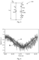
  • Figure 3 shows an equivalent circuit of an ultrasonic transducer showing the mechanical series resonant circuit given by a so-called mechanical capacitance CM, a mechanical inductance LM and a mechanical resistance RM. These three elements represent the electrical behavior of the ultrasonic transducer as far as it is depending on the mechanical behavior of the ultrasonic transducer.
  • this equivalent circuit 300 when in operation, explains the components of the overall current i m which is driven into the ultrasonic transducer which is split into the capacitance current ic and the main current component i'. Accordingly, the equivalent circuit 300 also shows the instrument voltage u m .
  • Figure 4 shows a diagram of two sin signals with different phase angles and thus having a phase shift with respect to each other. Both sin signals comprise white noise and for both sin signals the first harmonic is calculated and thus reconstructed using the first harmonic Fourier trigonometric coefficients a 1 and b 1 .
  • the resulting sin signals A and B are shown in Figure 4 . Accordingly, these two signals A and B are given each by their first harmonic Fourier trigonometric coefficients a 1 and b 1 and these Fourier coefficients can be converted into the actual phase shift between signals A and B using the atan2 function as explained above and as will be further explained below.
  • phase shift between the relevant signals i.e. the voltage and the current
  • the phase shift between the relevant signals can be determined in the digital domain using a robust algorithm that does not require low-pass filtering as it automatically extracts the first harmonic of the signal.
  • x[k] are the current/voltage samples
  • sin 2 ⁇ k N equals the reference signal that is used by the amplifier and created via a numerically controlled oscillation (NCO).
  • NCO numerically controlled oscillation
  • the relative phase shift of the signal can then be calculated as atan2( a 1 , b 1 ).
  • phase shift between the voltage and current is therefore atan2( a 1,u , b 1, u ) - atan2( a 1, i , b 1, i ).
  • an ultrasonic inverter implements voltage, current and power limits.
  • the current through the instrument consists of a main current component, and can be denoted as “mechanical” part, and a capacitive component and can be denoted as “capacitive” part or capacitive current flowing through the electrical capacitance.
  • This capacitive current should be compensated for two reasons. First, the phase shift must be calculated between the voltage and the "mechanical" current. Second, the ultrasonic amplifier usually operates in a constant "mechanical" current mode.
  • the current can be compensated by subtracting the current through the capacitance which equals the derivative of the measured voltage times the electrical capacitance of the instrument. That is expressed in the following formula in which i'(t) is the main current component, i.e. the current without the capacitive part, i meas ( t ) is the overall current, u meas ( t ) is the instrument voltage and i c ( t ) is the capacitive current component.
  • the residual represents the further harmonics and as only the first harmonic is considered, the residuals can be neglected. Accordingly said formulas can be written as: i meas t ⁇ a 1 , i ⁇ cos ⁇ 0 t + b 1 , i ⁇ sin ⁇ 0 t u meas t ⁇ a 1 , u ⁇ cos ⁇ 0 t + b 1 , u ⁇ sin ⁇ 0 t
  • CE ⁇ 0 I meas , rms U meas , rms ⁇ ⁇ 0 ⁇ meas
  • the measured admittance of the instrumented at the measurement frequency scaled by the ratio between the actual resonance frequency and the measurement frequency.

Landscapes

  • Health & Medical Sciences (AREA)
  • Engineering & Computer Science (AREA)
  • Life Sciences & Earth Sciences (AREA)
  • Surgery (AREA)
  • Biomedical Technology (AREA)
  • General Health & Medical Sciences (AREA)
  • Medical Informatics (AREA)
  • Public Health (AREA)
  • Molecular Biology (AREA)
  • Heart & Thoracic Surgery (AREA)
  • Animal Behavior & Ethology (AREA)
  • Nuclear Medicine, Radiotherapy & Molecular Imaging (AREA)
  • Veterinary Medicine (AREA)
  • Mechanical Engineering (AREA)
  • Dentistry (AREA)
  • Primary Health Care (AREA)
  • Epidemiology (AREA)
  • General Business, Economics & Management (AREA)
  • Business, Economics & Management (AREA)
  • Multimedia (AREA)
  • Physics & Mathematics (AREA)
  • Plasma & Fusion (AREA)
  • Otolaryngology (AREA)
  • Apparatuses For Generation Of Mechanical Vibrations (AREA)
  • Surgical Instruments (AREA)

Abstract

The invention relates to a method for controlling an ultrasonic transducer (206) of an electrosurgical instrument (102, 202), the ultrasonic transducer (206) is driven by an alternating electrical overall current signal (im), having a signal frequency (f), driving the overall current signal (im) results in an alternating electrical instrument voltage signal (um) of the transducer (206), depending on a mechanical oscillation of the transducer (206), the instrument voltage signal (um) having a transducer phase shift with respect to a main current component of the overall current signal (im) depending on the mechanical oscillations of the transducer, the ultrasonic transducer (206) is having a fluctuating mechanical resonance frequency, an amplifier (204) is controlled to provide the electrical overall current signal (im) and adjust the signal frequency (f) towards the resonance frequency depending on the transducer phase shift, and for determining the transducer phase shift, calculating signal coefficients for the main current component and the instrument voltage signal (um), the signal coefficients being representative for a phase relationship of the main current component or the instrument voltage signal respectively with respect to a common reference signal, and calculating from the signal coefficients the transducer phase shift.

Description

  • The present invention is directed to a method for controlling an ultrasonic transducer of an electrosurgical instrument. The invention is also directed to an electrosurgical generator for controlling an ultrasonic transducer of an electrosurgical instrument. The invention is also directed to an electrosurgical installation comprising an electrosurgical generator and an ultrasonic transducer of an electrosurgical instrument connected to the electrosurgical generator.
  • Ultrasonic transducers are used to transform an alternating electrical signal into a mechanical oscillation of an electrosurgical instrument having an ultrasonic frequency. In order to do that, the alternating electrical signal is basically stimulating the mechanical oscillation at a resonance frequency of the ultrasonic transducers.
  • Ultrasonic transducers can be modelled according to an equivalent circuit shown in Figure 3. The model shows a mechanical resonance circuit as an electrical equivalent (CM + LM + RM) and the parallel electrical capacitance (CE).
  • Ultrasonic transducers need to be driven at their mechanical resonance frequency. Since the resonance frequency changes with mechanical load, a control loop may be required to track the changing resonance frequency. A PLL can be used to adjust the frequency according to the measured phase shift between the voltage across the transducer and the current of the electrical equivalent of the mechanical resonance circuit, which can be understood as the mechanical current. When the phase shift is positive, the resonance circuit is inductive, and the frequency is too high. When the phase shift is negative, the resonance circuit is capacitive, and the frequency is too low.
  • A possible control loop may contain analogue sensors, ADCs and a digital controller (FPGA) that drives the amplifier with a calculated frequency. The controller may determine the phase shift between current and voltage by comparing their respective zero-crossings in the time domain.
  • Since zero-crossing detection is very sensitive to noise, the current and voltage signals must be filtered very carefully using a low-pass filter.
  • Filtering the signals in the digital domain is challenging. On the one hand, the signals must be oversampled by a high factor to accurately determine the instance where the signal crosses zero. On the other hand, a robust FIR low-pass filter requires many taps when the cut-off frequency is low compared to sampling frequency.
  • One possibility to solve this problem is by filtering the signals in the analog domain. This introduces the problem that filters produce a phase shift of the signals. Therefore, both analog filter paths need to be matched very closely to make sure that no additional relative phase shift is introduced. This requires complex filter structures with tightly tolerated components.
  • Accordingly, an object of the present invention is to address at least one of the above-mentioned problems. In particular, a solution shall be provided for improving the control of an ultrasonic transducer, in particular a solution shall be provided for identifying the mechanical resonance frequency of ultrasonic transducers in an improved manner and/or made more reliable. At least a solution shall be suggested which is an alternative solution with respect to known solutions.
  • According to the invention, a method is suggested according to claim 1. Thus, a method for controlling an ultrasonic transducer of an electrosurgical instrument is suggested. Such ultrasonic transducer is driven by an alternating electrical overall current signal having a signal frequency. Such transducer may be driven mainly by means of a current source having a voltage limit.
  • Such overall current signal is resulting in an alternating electrical instrument voltage signal of the transducer, depending on a mechanical oscillation of the transducer. In other words, the alternating electrical overall current signal, which can be a mainly sinusoidal current signal, is applied to the transducer. Depending on the transducer, the instrument voltage signal results. The shape of the instrument voltage signal mainly depends on a mechanical oscillation of the transducer.
  • The instrument voltage signal has a transducer phase shift with respect to a main current component of the overall current signal depending on the mechanical oscillations of the transducer. Thus, depending on the mechanical oscillations of the transducer, there will be a resulting phase shift, i.e. a phase shift between the instrument voltage signal and the main current component.
  • The ultrasonic transducer is having a fluctuating mechanical resonance frequency. Such mechanical resonance frequency might be in a range of 45 kHz - 50 kHz, in particular in the area of 46 kHz - 49 kHz. The resonance frequency may vary within this range. Of course it could also be outside of this range. However, the mechanical resonance frequency is fluctuating, at least slightly, and that may depend on the use of the electrosurgical instrument. For example, the resonance frequency may be different depending on whether the electrosurgical instrument is in contact with tissue or not.
  • There is also an amplifier controlled to provide the electrical overall current signal and adjust the signal frequency towards the resonance frequency depending on the transducer phase shift. Accordingly, the transducer phase shift indicates if and possibly how well the mechanical resonance frequency is met by the voltage signal and current signal. The resonance frequency is met, if there is no phase shift. Therefore, it is important to determine the transducer phase shift and adjust the signal frequency such that the amplitude of the phase shift decreases. In particular, a positive phase shift indicates that the resonance circuit is inductive and the frequency is too high and thus shall be reduced. On the other hand, when the phase shift is negative, the resonance circuit is capacitive, the frequency is too low and should be increased.
  • For determining the transducer phase shift, calculating signal coefficients for the current signal and the main voltage signal is suggested. Such signal coefficients shall be representative for a phase relationship of the main current component or the instrument voltage signal, respectively, with respect to a common reference signal. Accordingly, there are calculated signal coefficients for the main current component which are representative for a phase relationship of the main current component with respect to a common reference signal and there are signal coefficients for the instrument voltage signal calculated which are representative for a phase relationship of the instrument voltage signal with respect to the common reference signal.
  • Such common reference signal may be predetermined for the purpose of comparison. However, such common reference signal may also just be a theoretical or virtual reference signal. As will be explained further below, a calculation shall be used for calculating said signal coefficients for the main current component and also for the instrument voltage signal, using the same algorithm and using sampled values of a current signal and the instrument voltage signal, respectively, for the same time interval. In this way, using the same time interval, there are the same boundary conditions for calculating the signal coefficients for both signals resulting in having the same common reference signal. Accordingly, the relationship regarding the transducer phase shift can be identified when for both signals the same common reference signal is considered or is at least underlying the calculation without explicitly giving this common reference signal.
  • It is further suggested calculating from the signal coefficients the transducer phase shift.
  • Accordingly, the signal coefficients can be calculated characterizing the particular signal also with respect to their phase relationship with respect to the common reference signal and such phase relationship can also be denoted as phase angle. Accordingly, these signal coefficients also specify the phase angle of both signals and in this way the transducer phase shift can be calculated, in particular by subtracting the one phase angle from the other. In this way, the transducer phase shift can be calculated in an easy and reliable manner without comparing any signal waveforms of the measured signals. It can also be done without identifying a zero crossing, or other significant point of the two signals.
  • In particular, for calculating the signal coefficients, sampled values of both signals for a full period or at least for a half period are taken into account. Accordingly, the result is in particular two coefficients for each signal, thus in total four coefficients, which are calculated based on many sampled values. For example, each signal may be measured for one period using 100 samples each, maybe more. With respect to this example, two coefficients of one sampled signal are calculated based on 100 samples.
  • In this way, problems of any noise of the signals can be at least reduced.
  • According to one aspect, it is suggested that depending on the calculated transducer phase shift the signal frequency is adjusted to match the mechanical resonance frequency or to get closer to it. Accordingly, the transducer phase shift is calculated and it indicates a deviation between the mechanical resonance frequency and the signal frequency. Therefore, the signal frequency is adjusted to match the mechanical resonance frequency, at least to better match the mechanical resonance frequency. It was found that it is not necessary to identify the mechanical resonance frequency, but only to identify whether the signal frequency deviates from it.
  • It is in particular suggested to determine whether the signal frequency is above or below the resonance frequency and then raise or reduce the signal frequency accordingly to get closer to the resonance frequency.
  • Raising or reducing the signal frequency to get closer to the resonance frequency can be done in different ways. One possibility is to raise or reduce the signal frequency by a constant value. Such discrete way is in fact almost a continuous approach as there is a high repetition frequency for performing such raising or reducing. Thus, a difference between the signal frequency and the resonance frequency leads to a change, in particular small change of the signal frequency letting it get at least a little bit closer to the mechanical resonance frequency. This step is continuously repeated including repeating the calculating of the transducer phase shift. Accordingly, such step of adjusting is repeated quite often and each time the signal frequency gets a little bit closer to the mechanical resonance frequency, until it is almost reached.
  • Another possibility is to use a feedback control loop having a PID, or PI-control. According to the integral part of the control, the signal frequency found will keep its value when the input is zero.
  • There are thus different possibilities to design such feedback control loop. One is to use PI or PID-control and another is to increase by a constant value. In both cases, the feedback can be the calculated transducer phase shift or a calculated difference between the signal frequency and a calculated, at least roughly calculated, mechanical resonance frequency. In both cases, the input value tends to zero with the signal frequency matching the mechanical resonance frequency. It was found that it is easiest to just feedback the calculated transducer phase shift and just to use a proportional factor in order to transfer the transducer phase shift to a frequency difference between the signal frequency and the mechanical resonance frequency. Such proportional factor can be calculated or determined in a simulation or determined by measurements during a test operation, when the mechanical resonance frequency is measured or estimated.
  • However, it is also possible and suggested as one aspect to calculate an actual value of the mechanical resonance frequency depending on the calculated transducer phase shift and to set the signal frequency depending on the calculated mechanical resonance frequency, i.e. set the signal frequency to the mechanical resonance frequency. It was found that the calculated transducer phase shift can be correlated to a frequency difference between the signal frequency and the mechanical resonance frequency. As the signal frequency is known, as the alternating electric overall current signal is generated, the mechanical resonance frequency can thus quite precisely be calculated.
  • It was found that the variation of the mechanical resonance frequency is not high and in particular below 10% of a mean mechanical resonance frequency, possibly even below 5% of such mean mechanical resonance frequency. Accordingly, it can be assumed that the calculated transducer phase shift is almost proportional to the difference between the mechanical resonance frequency and the signal frequency. Therefore, the mechanical resonance frequency can quite easily and quite precisely be calculated in this way.
  • According to one aspect, it is suggested that the calculating of the signal coefficients is based on samples of the overall current signal and samples of the instrument voltage signal. In this way, these values can be sampled during a control cycle and each time new values can be calculated, a new transducer phase shift can be calculated and the signal frequency can be adapted accordingly.
  • Accordingly, the instrument voltage signal will be measured and the overall current signal may also be measured. However, the overall current signal may also just be known as it is generated as part of this the method, in particular by an electrosurgical generator generating such current signal.
  • Based on such sampled values, a control cycle can be implemented calculating the transducer phase shift for each sample time and thus also adjusting the signal frequency at each sample time.
  • According to one aspect, the signal coefficients characterize the first harmonic of the corresponding signal. I.e. two signal coefficients of the main current component characterize the first harmonic of the main current component and two coefficients of the instrument voltage signal characterize the first harmonic of the instrument voltage signal. Such coefficients can be calculated in a quasi-continuous way using a fast Fourier transform.
  • In this way, for each control cycle and thus for each sample time it is possible to calculate updated signal coefficients for the main current component and the instrument voltage signal and based on that calculate the transducer phase shift.
  • In this way, a reliable way of calculating is provided avoiding to observe any zero-crossings of the particular signals, which is otherwise often used to calculate a particular frequency and a particular phase angle.
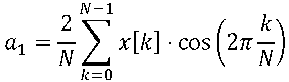
  • According to one aspect, it is suggested that for each signal, i.e. for the main current component and the instrument voltage signal, the signal coefficients are the first harmonic Fourier trigonometric coefficients a1 and b1 calculated according to the formula a 1 = 2 N k = 0 N 1 x k cos 2 π k N
    Figure imgb0001
    b 1 = 2 N k = 0 N 1 x k sin 2 π k N
    Figure imgb0002
    wherein
    • x[k] are samples of the corresponding signal and
    • N is the number of samples per signal, and wherein
    • the samples are taken over a predetermined time interval and/or a time interval of one period corresponding to a nominal value of the resonance frequency.
  • This way of calculating the signal coefficients also uses samples of the corresponding signal, i.e. samples of the current signal and samples of the main voltage signal. The variable k can also be understood as the discrete sample time and the samples from k=0 to k = N-1 can reflect the samples of one period of the signal frequency.
  • Accordingly, it was also found that the signal frequency is well-known, as the overall current signal is generated and thus its frequency is known. Accordingly, the period of such alternating, i.e. mainly sinusoidal signal, is also well-known. Therefore, said formula for calculating the signal coefficients is applied to sampled signals of exactly one signal period leading to a quite precise result of calculating this first harmonic Fourier trigonometric coefficients a1 and b1.
  • Of course, it is also possible to use samples of two or more whole number of signal periods.
  • Even for such calculation using a complete signal period a fast calculation and thus fast control is still possible, as the underlying signal frequency is expected to be in the range of 40 kHz and 50 kHz. It may also be a bit higher or a bit lower. However, as the signal frequency is this high, the time needed to sample values of one signal period is in the range of approximately 20 µs. It was also found that taking samples over one signal period is enough as it is enough to change the frequency of the current signal per signal period.
  • According to one aspect, it is suggested that for the signal coefficients for each signal being the first harmonic Fourier trigonometric coefficients a1 and b1, the absolute phase shift (ϕa for each signal is calculated based on the formula ϕa = atan2(a1,b1) and the transducer phase shift is calculated as a difference of the absolute phase shifts of both signals. I.e., the transducer phase shift is calculated as the difference of the absolute phase shifts of the main current component and the instrument voltage signal.
  • Accordingly, there is a quite adequate calculation of the absolute phase shifts and thus the transducer phase shift which provides good results and is not depending on observing any zero-crossings. Such calculation is also tolerant to some noise and other distortions of the corresponding signal, i.e. of the current signal or main voltage signal.
  • According to one aspect, it is suggested that
    • for the signal coefficients for each signal being the first harmonic Fourier trigonometric coefficients a1 and b1
    • the transducer phase shift is calculated by an approximation such that the transducer phase shift ϕt is calculated as the difference of the quotient a1/b1 of both signals, in particular ϕt is calculated using the formula φ t = a 1 , i / b 1 , i a 1 , u / b 1 , u
      Figure imgb0003
    with
    • a1,i and b1,i being the first harmonic Fourier trigonometric coefficients a1 and b1 of the main current component and
    • a1,u and b1,u being the first harmonic Fourier trigonometric coefficients a1 and b1 of the instrument voltage signal.
  • Accordingly, the transducer phase shift can be calculated in an easy way and the use of the trigonometric calculation atan2 can be avoided. It was found that the transducer phase shift, i.e. said corresponding phase shift angle, is expected to be quite small, i.e. much below 30°, that such approximation is feasible. It was also found that according to the suggested adjusting of the signal frequency towards the mechanical resonance frequency, it is possible by such control to take care of having a good match of the signal frequency to the mechanical resonance frequency and thus have a small transducer phase shift. Accordingly, the suggested approximation can be used.
  • It was also found that the calculation of the transducer phase shift is only needed to adjust the signal frequency towards the mechanical resonance frequency. Accordingly, any inaccuracy of the calculated transducer phase shift is not or not much influencing the control of adjusting the signal frequency. In particular, inaccuracies are only expected for large transducer phase shifts. But at large transducer phase shifts inaccuracies of the adjusting of the signal frequency are acceptable. A higher accuracy is needed when the signal frequency is close to match the mechanical resonance frequency. However, at this stage, the inaccuracy according to the approximation is also quite small resulting in a fairly small control inaccuracy if at all noticeable.
  • According to one aspect, it is suggested that calculating the transducer phase shift and/or adjusting the signal frequency to match the mechanical resonance frequency or to get closer to it is repeated regularly for tracking changes of the mechanical resonance frequency, and in particular the calculating or adjusting is repeated with a predetermined repetition frequency being at least one repetition per 10 signal periods, preferably at least one repetition per 2 signal periods, in particular one repetition per signal period.
  • It was found that by this permanent repetition the signal frequency can be controlled to be very close to the mechanical resonance frequency. By repeating the calculation of the transducer phase shift and/or the adjusting of the signal frequency, the ultrasonic transducer and thus the corresponding electrosurgical instrument can almost always be operated effectively.
  • The mechanical resonance frequency may depend on the electrosurgical instrument being in touch with tissue or other material or not being in touch with any material. Accordingly, just a small movement of the electrosurgical instrument when in operation may change said situation and accordingly the mechanical resonance frequency may also change. However, repeating the calculating and/or adjusting with one repetition per signal period leads to a fast tracking of the changed situation, as the signal period is approximately in the range of 20 µs. Compared to that, a manual movement of the electrosurgical instrument when in operation can be quite slow when compared to said high repetition frequency.
  • Therefore, the change of such situation can be tracked quickly enough to keep the electrosurgical instrument in good operation. As explained above, such ultrasonic transducer and thus such ultrasonic electrosurgical instrument which is used as the electrosurgical instrument only operates well if the overall current signal and the resulting alternating electrical voltage signal almost match the mechanical resonance frequency. By this quick repetition of the calculating and/or adjusting such good operation can be ensured.
  • Of course, it would also be possible to slow the repetition frequency down to one repetition per 10 signal periods, or a value in between this one repetition per 10 signal periods and the one repetition per 1 signal period.
  • According to one aspect, it is suggested that the signal coefficients, in particular the signal coefficients for each signal being the first harmonic Fourier trigonometric coefficients a1 and b1, are used to calculate an rms-value of the current signal, in particular of the main current component, and/or an rms-value of the voltage signal and/or a real power value of both signals. Accordingly, each rms-value and/or the real power value of both signals is calculated based on the first harmonic of the current signal and/or the voltage signal.
  • This is advantageous as there is a clear relationship between these frequencies according to the first harmonic and the deflection of the ultrasonic transducer and/or the electrosurgical instrument being an ultrasonic electrosurgical instrument. Accordingly, this part of the signal corresponding to the mechanical deflection is thus also the characteristic signal for considering this deflection. Therefore, considering such rms-values and/or the real power value provides the best relationship between the considered electrical signals and the mechanical behavior.
  • According to one aspect, it is suggested that
    • the overall current signal, having a main current component and a capacitive current component, the capacitive current component, depending on a capacitance of the transducer, and
    • the main current component is calculated by subtracting the capacitive current component from the overall current signal, in particular from a measured alternating electrical current signal of the transducer, and/or
    • first harmonic Fourier trigonometric coefficients a1 and b1 are used for calculating the capacitive current signal, wherein in particular
    • the capacitive current component ic is calculated for the capacitance C and the frequency ω using the formula: i C = C * ω * a 1 * cos ω * t or i C = C * ω * b 1 * sin ω * t .
      Figure imgb0004
  • The nominal frequency ω0 can be used for ω. That is relevant for any formula discussed.
  • Accordingly, it was found that the overall current, which is in particular the current that is measured, has a main current component and a capacitive current component. Hence, basically there is the main current component and the capacitive current component as an additional component. This capacitive current component depends on a capacitance of the transducer. This capacitive current component is basically - simply speaking - not involved in driving the mechanical movement of the ultrasonic electrosurgical instrument.
  • However, such capacitive current component results in a deviation between the phase angle of the voltage signal and the overall current signal which is not indicating any deviation between the signal frequency and the mechanical resonance frequency. Only the deviation of the phase angle between the main current component and the instrument voltage signal indicates the deviation between the signal frequency and the mechanical resonance frequency. Accordingly, the overall current signal is cleared from this capacitive current component.
  • Accordingly, the main current component is calculated by subtracting the capacitive current component from the overall current signal. The overall current signal can be measured and thus the measured alternating electrical current signal can be used as the overall current signal. Of course, it might be possible that by generating this overall current signal the properties of this overall current signal might be well-known and these properties could be used instead of measuring the alternating electrical current signal, i.e. the overall current signal.
  • With the known capacitance of the ultrasonic transducer the capacitive current component can be calculated. One way of doing this is to use the first harmonic Fourier trigonometric coefficients a1 and b1. These can be calculated as explained above. In this way, basically only the first harmonic of the current signal is considered which is advantageous as basically only this first harmonic component influences the phase shift caused by the capacity. In addition, using the first harmonic Fourier trigonometric coefficients is reliable and tolerant to noise and distortions on the signal. In particular, the given formula provides a simple way to calculate the capacitive current component.
  • According to a further aspect, it is suggested that
    • for calculating the transducer capacitance,
    • the overall current signal is generated having a test frequency being different to the nominal value of the resonance frequency at least by a minimum frequency difference, resulting in an instrument voltage signal,
    • the signal coefficients are calculated based on the overall current signal and the resulting instrument voltage signal having the test frequency, and
    • the transducer capacitance is calculated based on these signal coefficients, wherein in particular
    • the minimum frequency difference is at least 10kHz, in particular at least 20 kHz.
  • Accordingly, it was found that the main current component driving the mechanical oscillation of the transducer and thus the electrosurgical instrument is not very dominant when the signal frequency is very different from the mechanical resonance frequency. In this case, which is reached by having this minimum frequency difference of at least 10 kHz, the capacity is basically the only characteristic of the transducer influencing the overall current signal that is driven through the transducer. Accordingly, the relationship between the overall current signal and the resulting instrument voltage signal gives a clear indication of the capacitance.
  • Underlying the choice of a minimum frequency of at least 10 kHz is the understanding that the resonance frequency is in a range of about 40 kHz to 50 kHz. Accordingly, this minimum frequency of 10 kHz is a significant frequency difference resulting in almost not at all triggering any mechanical oscillation of the transducer or electrosurgical instrument. The minimum frequency could also be at least 20 kHz. In this way, the frequency is even further away from the mechanical resonance frequency. However, it should be kept in mind that the test frequency should at least not deviate too much, as in case of a too high deviation any nonlinearities of the capacitance can possibly not be neglected anymore. In that case, an inaccuracy of calculating the capacitance could be a result.
  • According to one aspect, it is suggested that
    • for calculating the signal coefficients, in particular for calculating the signal coefficients of the instrument voltage signal,
    • the instrument voltage signal is modified into a modified voltage signal by adding a virtual voltage signal, wherein
    • the virtual voltage signal is calculated by multiplying the main current component with a predetermined virtual resistance, and in particular
    • as the main current component a previously calculated main current component is used and,
    • the previously calculated main current signal is calculated based on the signal coefficients previously calculated for the voltage signal and for the main current signal and/or
    • the modified voltage signal is calculated directly using the signal coefficients previously calculated for the voltage signal and for the main current signal and/or
    • coefficients of the modified voltage signal are calculated directly using signal coefficients previously calculated for the voltage signal and for the main current signal and using the predetermined virtual resistance.
  • The underlying idea of this aspect is that the measured voltage might have a very small amplitude in particular in view of noise which is often present on measured voltage signals. Thus, the evaluation or calculation might lead to problems, such as stability problems if noise level is too high, in relation to the signal amplitude.
  • It was found that such situation may occur if the instrument is in operation and operating at or close to the resonance frequency. In that case such virtual voltage signal, which is not suffering from noise, is added to the measured voltage signal and the result is a signal having an amplitude being high enough when compared with the noise amplitude.
  • As this added virtual signal is not exactly reflecting the actual voltage at the transducer, it might have a slightly different phase angle and that might result in a slight change of the determined value of the frequency. That might result in a small frequency deviation from the ideal resonance frequency, but such deviation is acceptable. It was also found that because of the frequent repetition of setting the frequency, only a small fluctuation about the ideal value of the frequency will result. That was found to be acceptable as depending on the load of the transducer the ideal resonance frequency will fluctuate also and thus the frequency must be adjusted quite often.
  • However, it was also found that when the frequency is not too close to the resonance frequency, the measured voltage is also higher and high enough to be measured without problems, i.e. high enough to be distinguished from the noise level. Accordingly, the virtual resistance can be chosen such, that the virtual voltage signal is only significant when the frequency is at or close to the resonance frequency. It is not significantly high, i.e. lower than the measured voltage signal, when the signal frequency deviates significantly from the resonance frequency.
  • Accordingly, when the signal frequency deviates significantly from the resonance frequency, the influence of the virtual resistance and/or the resulting virtual voltage can be neglected and accordingly the deviation from the resonance frequency can be detected with high precision enabling the operating point to move towards the resonance frequency.
  • Preferably the virtual voltage signal is chosen such, that its average rms-value is between 3 to 20 times, in particular 5 to 10 times the rms average value of the voltage signal at the resonance frequency. Based on known average values of the voltage at the resonance frequency and corresponding main current component, the virtual resistance can be calculated accordingly. The virtual resistance may be in a range of about 100-200 Ohms. It could also be chosen based on experiences.
  • For calculating the main current component, the following formula can be used, which is explained further below: i t a 1 , i CE ω 0 b 1 , u cos ω 0 t + b 1 , i + CE ω 0 a 1 , u sin ω 0 t
    Figure imgb0005
  • However, based on that it is also possible to directly calculate the modified voltage, i.e. the modified voltage signal using the signal coefficients previously calculated for the voltage signal and for the main current signal using the formula, which is explained further below: u t a 1 , u + R virt a 1 , i CE ω 0 b 1 , u cos ω 0 t + b 1 , u + b 1 , i + CE ω 0 a 1 , u sin ω 0 t
    Figure imgb0006
  • This way, even the modified voltage signal can be calculated quite easily, just using these coefficients.
  • For the aspect that coefficients of the modified, and compensated, voltage signal a1,u' and b1,u' are calculated directly using signal coefficients previously calculated for the voltage signal and for the main current signal and using the predetermined virtual resistance, the following relationship can be used which is also explained below in more detail: u t a 1 , u + R virt a 1 , i CEω 0 b 1 , u , b 1 , u + R virt b 1 , u + CEω 0 a 1 , u
    Figure imgb0007
  • Accordingly a1,u' and b1,u' can be calculated as follows: a 1 , u = a 1 , u + R virt a 1 , i CEω 0 b 1 , u
    Figure imgb0008
    b 1 , u = b 1 , u + R virt b 1 , i + CEω 0 a 1 , u
    Figure imgb0009
  • According to one aspect, it is also suggested an electrosurgical generator for controlling an ultrasonic transducer of an electrosurgical instrument adapted to execute a method according to any of the preceding aspects.
  • Thus, the electrosurgical generator may have any corresponding control unit such as a digital controller, e.g. an FPGA and an amplifier connected to the controller and driven by the controller. The controller may provide a calculated frequency that will be submitted to the amplifier and the amplifier will then generate a corresponding current signal. The controller determines the phase shift between current and voltage and will base on that determination control the amplifier.
  • Accordingly, any method according to the explained aspects can be implemented at least partially as a computer program on such controller.
  • The electrosurgical generator may also comprise current and voltage sensors for measuring an overall current signal generated by the amplifier and for measuring a resulting instrument voltage signal. Such sensors may particularly be connected to the controller and/or to the amplifier.
  • There is also suggested an electrosurgical installation comprising an electrosurgical generator as explained above and an electrosurgical instrument. The electrosurgical instrument is connected to the electrosurgical generator and the electrosurgical instrument may have an ultrasonic transducer. In particular, the amplifier of the electrosurgical generator is connected to the ultrasonic transducer and provides an overall current signal to the ultrasonic transducer.
  • The invention will be explained by way of example based on the accompanying figures in more detail.
  • Figure 1
    shows an electrosurgical generator having an electrosurgical instrument connected.
    Figure 2
    shows a simplified control structure.
    Figure 3
    shows an equivalent circuit of an ultrasonic transducer.
    Figure 4
    shows two sin signals reconstructed by calculating first order Fourier coefficients.
  • Figure 1 shows an electrosurgical generator 100 to which an electrosurgical instrument 102 is connected operating on a tissue 104 just schematically illustrated.
  • The electrosurgical generator 100 comprises a frequency converter 106 which is controlled by a control device 108. The frequency converter when in operation provides at its output 110 an overall current signal which is applied to the attached electrosurgical instrument 102, resulting in an instrument voltage. The instrument voltage is a simplified term for the instrument voltage signal and is thus a synonym for it.
  • There is a voltage sensor 112 for measuring the voltage signal and a current sensor 114 for measuring the overall current signal. These sensors 112, 114 are connected to the control device 108 for further consideration.
  • The control device 108 calculates from the current sample values provided by the current sensor 114 signal coefficients. Based on that, the control device 108 controls the frequency converter 106. Accordingly, at the frequency converter output, the overall current signal is generated depending on the calculated coefficients.
  • It is also possible that the voltage sensor 112 and/or the current sensor 114 are connected to the frequency converter 106 directly. It is also possible that the control device 108 is part of the frequency converter 106.
  • Figure 2 shows a simplified control structure 200 for controlling an ultrasonic transducer of an electrosurgical instrument. For this purpose, Figure 2 shows schematically such electrosurgical instrument 202 having an ultrasonic transducer. The electrosurgical instrument 202 and thus its ultrasonic transducer is connected to an amplifier 204. The amplifier 204 can be identical to the frequency converter 106 of Figure 1, or similar, or can be part of such frequency converter.
  • The amplifier 204 provides an alternating electrical overall current im which is thus driven into the ultrasonic transducer 206 of the electrosurgical instrument 202. The overall current is a simplified term for the overall current signal and is thus a synonym for it. Driving this overall current im results in an instrument voltage um. The overall current im and accordingly the instrument voltage um have a signal frequency f. The transducer 206 works best when this signal frequency f matches a mechanical resonance frequency of the transducer 206. To ensure that, the overall current im and the instrument voltage um are measured with a voltage sensor 208 and a current sensor 210. Accordingly, the instrument voltage um and the overall current im are measured. For simplification it is assumed that the overall current and its measured value are the same and that the instrument voltage and its measured value are also the same.
  • The measured instrument voltage um is given to a voltage Fourier transform block 212 calculating the first harmonic Fourier trigonometric coefficients a1,u and b1,u of the voltage signal. Similarly, the measured overall current im is given to a current Fourier transform block 214 calculating the first harmonic trigonometric coefficients a1,i and b1,i of the current signal.
  • Accordingly, the first Fourier trigonometric coefficients a1,i and b1,i of the measured overall current im are representing the overall current im. However, for calculating the phase shift ϕ which is relevant for identifying a deviation of the signal frequency f from the mechanical resonance frequency fR may be cleared by a capacitive current component. This capacitive current component can be calculated using the first harmonic Fourier trigonometric coefficients a1,u and b1,u of the measured instrument voltage um and using the known capacitance C of the ultrasonic transducer 206. If the ultrasonic transducer capacitance C is not known, it can be measured as explained above, but it could also be known.
  • However, based on this first harmonic trigonometric coefficients a1,u and b1,u and the known capacitance C of the transducer 206, a capacitance current component of the overall current im can be calculated and subtracted from the overall current im.
  • This calculation is done in the modification block 216. The modification block 216 therefore receives the first harmonic trigonometric coefficients a1,u and b1,u of the measured instrument voltage um and receives the first harmonic Fourier trigonometric coefficients a1,i and b1,l of the current signal and also the capacitance C of the ultrasonic transducer 206. One possibility to clear the overall current im from its capacitance current component is to use these first harmonic trigonometric coefficients. The underlying idea is that only the first harmonic of the overall current and also only the first harmonic of the instrument voltage is considered, as only that is relevant for setting the signal frequency f and only that is relevant for considering the capacitance current component. Accordingly, not the whole overall current im is used but only the first harmonic and accordingly it is possible to only consider the corresponding coefficients of the first harmonic of the overall current as well as of the instrument voltage. This is done in the modification block 216 and it was also found that it is possible to subtract the capacitance current component by just modifying the first harmonic Fourier trigonometric coefficients a1,i and b1,l into a'1,i and b'1,i.
  • The overall current im is thus cleared from the capacitance current component by subtracting it and the result is the remaining main current component. The first harmonic of this main current component is thus described by the modified first harmonic Fourier trigonometric coefficients a'1,i and b'1,i.
  • Accordingly, for calculating the phase shift between the main current component and the instrument voltage, the corresponding coefficients a'1,i and b'1,i, as well as a1,u and b1,u are given into the phase shift calculation block 218. This phase shift calculation block 218 thus calculates the phase shift ϕ and this calculated phase shift ϕ is inputted in the frequency adjustment block 220. The frequency adjustment block 220 also receives the signal frequency f which is the actual signal frequency and adds a small offset Δf or subtracts such small offset Δf or leaves the signal frequency f unchanged if the calculated phase shift ϕ is zero or below a relevance threshold.
  • Accordingly, the result of the frequency adjustment block 220 is the adjusted frequency fa. This adjusted frequency fa is given to the amplifier 204 and the amplifier 204 takes this adjusted frequency fa as the new signal frequency f. Accordingly, the amplifier 204 generates and outputs the overall current im having this signal frequency f. Accordingly, this overall current im is given into the electrosurgical instrument 202 resulting in the instrument voltage um as explained above. With these new values for the overall current im and the instrument voltage um, the next control cycle can begin.
  • Figure 3 shows an equivalent circuit of an ultrasonic transducer showing the mechanical series resonant circuit given by a so-called mechanical capacitance CM, a mechanical inductance LM and a mechanical resistance RM. These three elements represent the electrical behavior of the ultrasonic transducer as far as it is depending on the mechanical behavior of the ultrasonic transducer.
  • In parallel, there is the electrical capacity CE which represents a capacitive behavior of this ultrasonic transducer which is not depending on the mechanical behavior of the ultrasonic transducer.
  • Accordingly, when in operation, this equivalent circuit 300 explains the components of the overall current im which is driven into the ultrasonic transducer which is split into the capacitance current ic and the main current component i'. Accordingly, the equivalent circuit 300 also shows the instrument voltage um.
  • Figure 4 shows a diagram of two sin signals with different phase angles and thus having a phase shift with respect to each other. Both sin signals comprise white noise and for both sin signals the first harmonic is calculated and thus reconstructed using the first harmonic Fourier trigonometric coefficients a1 and b1. The resulting sin signals A and B are shown in Figure 4. Accordingly, these two signals A and B are given each by their first harmonic Fourier trigonometric coefficients a1 and b1 and these Fourier coefficients can be converted into the actual phase shift between signals A and B using the atan2 function as explained above and as will be further explained below.
  • Further aspects and explanations helpful to better understand the invention are given below.
  • It was found that the phase shift between the relevant signals, i.e. the voltage and the current, can be determined in the digital domain using a robust algorithm that does not require low-pass filtering as it automatically extracts the first harmonic of the signal. The idea is to calculate the first harmonic Fourier trigonometric coefficients a1 and b1 of the current and voltage according to: a 1 = 2 N k = 0 N 1 x k cos 2 π k N
    Figure imgb0010
    b 1 = 2 N k = 0 N 1 x k sin 2 π k N
    Figure imgb0011
  • Where x[k] are the current/voltage samples, and sin 2 π k N
    Figure imgb0012
    equals the reference signal that is used by the amplifier and created via a numerically controlled oscillation (NCO). The samples of the cos function can be efficiently created with the same NCO.
  • The relative phase shift of the signal can then be calculated as atan2(a 1, b 1).
  • In total, four coefficients need to be calculated, two for the measured current imeas (t) and two for the measured voltage umeas (t), illustrated as follows : i meas t a 1 , i , b 1 , i
    Figure imgb0013
    u meas t a 1 , u , b 1 , u
    Figure imgb0014
  • The phase shift between the voltage and current is therefore atan2(a 1,u, b 1,u ) - atan2(a 1,i , b 1,i ). Either the two atan2 functions can be calculated separately or the atan2 difference identity may be used to reduce the calculation to a single atan2 function: atan 2 a 1 , u b 1 , u atan 2 a 1 , i b 1 , i = atan 2 a 1 , u b 1 , i a 1 , i b 1 , u , b 1 , u b 1 , i + a 1 , u a 1 , i
    Figure imgb0015
  • Although the atan2 function can be calculated efficiently with digital logic using the CORDIC algorithm, the atan2 function can be reduced to a division by linearizing the function at ϕ = 0 as the phase locked loop (PLL) makes sure that the phase shift is always close to 0: atan 2 y x = φ y x | φ 0
    Figure imgb0016
  • Typically, an ultrasonic inverter implements voltage, current and power limits. As a side-catch, the calculated Fourier coefficients can be directly converted into RMS current/voltage and real power according to: i RMS = a 1 , i 2 + b 1 , i 2 2
    Figure imgb0017
    u RMS = a 1 , u 2 + b 1 , u 2 2
    Figure imgb0018
    P = a 1 , i a 1 , u + b 1 , i b 1 , u
    Figure imgb0019
  • Additional improvements are suggested as follows:
    The following improvements are basically independent of the phase-shift detection algorithm but can be implemented very efficiently when using the Fourier coefficient based algorithm described above.
  • Compensation of electrical transducer capacitance can be done as follows.
  • The current through the instrument consists of a main current component, and can be denoted as "mechanical" part, and a capacitive component and can be denoted as "capacitive" part or capacitive current flowing through the electrical capacitance. This capacitive current should be compensated for two reasons. First, the phase shift must be calculated between the voltage and the "mechanical" current. Second, the ultrasonic amplifier usually operates in a constant "mechanical" current mode.
  • The current can be compensated by subtracting the current through the capacitance which equals the derivative of the measured voltage times the electrical capacitance of the instrument. That is expressed in the following formula in which i'(t) is the main current component, i.e. the current without the capacitive part, imeas (t) is the overall current, umeas (t) is the instrument voltage and ic (t) is the capacitive current component. i t = i meas t i c t = i meas t CE d u meas t dt
    Figure imgb0020
  • Calculating the derivative in the time domain and thus differentiation in the time domain is very sensitive to noise. Instead, the Fourier coefficients can be used to differentiate in the frequency domain:
    If the first harmonic Fourier coefficients of imeas(t) / umeas(t) are given by a 1,i , b 1,i and a 1,u , b 1,u , the current and voltage can be described by the formulas describing the Fourier Series: i meas t = a 1 , i cos ω 0 t + b 1 , i sin ω 0 t + residual
    Figure imgb0021
    u meas t = a 1 , u cos ω 0 t + b 1 , u sin ω 0 t + residual
    Figure imgb0022
  • The residual represents the further harmonics and as only the first harmonic is considered, the residuals can be neglected. Accordingly said formulas can be written as: i meas t a 1 , i cos ω 0 t + b 1 , i sin ω 0 t
    Figure imgb0023
    u meas t a 1 , u cos ω 0 t + b 1 , u sin ω 0 t
    Figure imgb0024
  • Based on that the coefficients are considered below implying that the above formulas are underlying the consideration. Thus the relationship can be symbolized and explained as follows, wherein the double arrows indicate that the coefficients on the right side shall be meant to be used in the corresponding formula as given above: i meas t a 1 , i , b 1 , i
    Figure imgb0025
    u meas t a 1 , u , b 1 , u
    Figure imgb0026
  • Based on that the Fourier coefficients of the voltage derivative can be calculated using the properties of the Fourier Series (s. above): d u meas t dt ω 0 b 1 , u , ω 0 a 1 , u
    Figure imgb0027
    i t = i meas t CE d u meas t dt a 1 , i CEω 0 b 1 , u , b 1 , i + CEω 0 a 1 , u
    Figure imgb0028
  • That is: i t a 1 , i CE ω 0 b 1 , u cos ω 0 t + b 1 , i + CE ω 0 a 1 , u sin ω 0 t
    Figure imgb0029
  • Differentiation in the time domain has become a multiplication in the frequency domain. The last formula is just for clarification as it might be enough to just use the changed coefficients for further consideration.
  • The compensation of the capacitive current component described above thus requires the factor CEω0 (CE*ω0 ) which equals the magnitude of the electrical capacitor admittance at the resonance frequency. When the capacitance is unknown, it can be determined by driving the instrument out of resonance and calculating CEω 0 = I meas , rms U meas , rms ω 0 ω meas
    Figure imgb0030
  • i.e., the measured admittance of the instrumented at the measurement frequency, scaled by the ratio between the actual resonance frequency and the measurement frequency.
  • A further suggestion is to use virtual instrument load.
  • When the mechanical load on the instrument is low, the amplitude of the voltage can become very low. This can make it difficult to determine the phase shift between voltage and current. To make the algorithm more robust, a virtual resistance can be added to the instrument by adding a virtual voltage to the measured voltage which is proportional to the (compensated) current. Accordingly, a modified voltage u'(t) results considering a virtual Resistance Rvirt: u t = u meas t + R virt i t
    Figure imgb0031
  • Again, this can be realized in the frequency domain very easily. Using the definitions from above: i meas t a 1 , i , b 1 , i
    Figure imgb0032
    u meas t a 1 , u , b 1 , u
    Figure imgb0033
    i t a 1 , i CEω 0 b 1 , u , b 1 , i + CEω 0 a 1 , u
    Figure imgb0034
  • Yields the Fourier coefficients for the modified (compensated) voltage: u t a 1 , u + R virt a 1 , i CEω 0 b 1 , u , b 1 , u + R virt b 1 , i + CEω 0 a 1 , u
    Figure imgb0035
  • That is: u t a 1 , u + R virt a 1 , i CE ω 0 b 1 , u cos ω 0 t + b 1 , u + b 1 , i + CE ω 0 a 1 , u sin ω 0 t
    Figure imgb0036
  • The approximately equal indicates that the further harmonics are neglected.
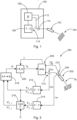
Claims (14)

  1. Method for controlling an ultrasonic transducer (206) of an electrosurgical instrument (102, 202),
    - the ultrasonic transducer (206) is driven by an alternating electrical overall current signal (im), having a signal frequency (f),
    - driving the overall current signal (im) results in an alternating electrical instrument voltage signal (um) of the transducer (206), depending on a mechanical oscillation of the transducer (206)
    - the instrument voltage signal (um) having a transducer phase shift with respect to a main current component of the overall current signal (im) depending on the mechanical oscillations of the transducer,
    - the ultrasonic transducer (206) is having a fluctuating mechanical resonance frequency,
    - an amplifier (204) is controlled to provide the electrical overall current signal (im) and adjust the signal frequency (f) towards the resonance frequency depending on the transducer phase shift, and
    - for determining the transducer phase shift,
    - calculating signal coefficients for the main current component and the instrument voltage signal (um), the signal coefficients being representative for a phase relationship of the main current component or the instrument voltage signal respectively with respect to a common reference signal, and
    - calculating from the signal coefficients the transducer phase shift.
  2. Method according to claim 1, characterized in that
    - depending on the calculated transducer phase shift
    - adjusting the signal frequency (f) to match the mechanical resonance frequency or to get closer to it, in particular
    - determining whether the signal frequency (f) is above or below the resonance frequency and
    - raising or reducing the signal frequency (f) accordingly to get closer to the resonance frequency, or
    - calculating an actual value of the mechanical resonance frequency depending on the calculated transducer phase shift and
    - setting the signal frequency (f) depending on the calculated mechanical resonance frequency.
  3. Method according to claim 1 or 2, characterized in that
    - the calculating of the signal coefficients is based on samples of the current signal and samples of the main voltage signal, in particular samples of the measured current signal and samples of the main voltage signal determined from the measured alternating electrical voltage of the transducer (206).
  4. Method according to any of the preceding claims, characterized in that
    - the signal coefficients characterize the first harmonic of the corresponding signal.
  5. Method according to any of the preceding claims, characterized in that
    - for each signal, in particular for the main current component and the instrument voltage signal (um) each, the signal coefficients are the first harmonic Fourier trigonometric coefficients a1 and b1 calculated according to the formula: a 1 = 2 N k = 0 N 1 x k cos 2 π k N
    Figure imgb0037
    b 1 = 2 N k = 0 N 1 x k sin 2 π k N
    Figure imgb0038
    wherein
    - x[k] are samples of the corresponding signal and
    - N is the number of samples per signal, and wherein
    - the samples are taken over a predetermined time interval and/or a time interval of one period corresponding to a nominal value of the resonance frequency.
  6. Method according to any of the preceding claims, characterized in that
    - for the signal coefficients for each signal being the first harmonic Fourier trigonometric coefficients a1 and b1
    - the absolute phase shift ϕa, for each signal is calculated based on the formula φ a = atan2 a 1 b 1
    Figure imgb0039
    - and the transducer phase shift is calculated as a difference of the absolute phase shifts of both signals.
  7. Method according to any of the preceding claims, characterized in that
    - for the signal coefficients for each signal being the first harmonic Fourier trigonometric coefficients a1 and b1
    - the transducer phase shift is calculated by an approximation such that the transducer phase shift ϕt is calculated as the difference of the quotient a1/b1 of both signals, in particular ϕt is calculated using the formula φ t = a 1 , i / b 1 , i a 1 , u / b 1 , u
    Figure imgb0040
    with
    a1,i and b1,i being the first harmonic Fourier trigonometric coefficients a1 and b1 of the main current component and
    a1,u and b1,u being the first harmonic Fourier trigonometric coefficients a1 and of the instrument voltage signal (um).
  8. Method according to any of the preceding claims, characterized in that
    - calculating the transducer phase shift and/or adjusting the signal frequency (f) to match the mechanical resonance frequency orto get closer to it, is repeated regularly for tracking changes of the mechanical resonance frequency, and in particular
    - the calculating or adjusting is repeated with a predetermined repetition frequency being at least one repetition per 10 signal periods, preferably at least one repetition per 2 signal periods, in particular one repetition per signal period.
  9. Method according to any of the preceding claims, characterized in that
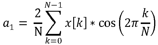
    - the signal coefficients, in particular the signal coefficients for each signal being the first harmonic Fourier trigonometric coefficients a1 and b1, are used to calculate
    - an rms-value of the current signal, and/or
    - an rms-value of the voltage signal and/or
    - a real power value of both signals, wherein in particular
    - each rms-value and/or the real power value of both signals is calculated based on the first harmonic of the current signal and/or the voltage signal.
  10. Method according to any of the preceding claims, characterized in that
    - the overall current signal (im), having a main current component and a capacitive current component, the capacitive current component, depending on a capacitance (C)of the transducer (206), and
    - the main current component is calculated by subtracting the capacitive current component from the overall current signal (im), in particular from a measured alternating electrical current signal of the transducer (206), and/or
    - first harmonic Fourier trigonometric coefficients a1 and b1 are used for calculating the capacitive current signal, wherein in particular
    - the capacitive current component ic is calculated for the capacitance (C) and the frequency ω using the formula: i C = C * ω * a 1 * cos ω * t or i C = C * ω * b 1 * sin ω * t .
    Figure imgb0041
  11. Method according to any of the preceding claims, characterized in that
    - for calculating a or the transducer capacitance (C),
    - the overall current signal (im) is generated having a test frequency being different to a or the nominal value of the resonance frequency at least by a minimum frequency difference, resulting in an instrument voltage signal (um),
    - the signal coefficients are calculated based on the overall current signal (im) and the resulting instrument voltage signal (um) having the test frequency, and
    - the transducer capacitance (C) is calculated based on these signal coefficients, wherein in particular
    - the minimum frequency difference is at least 10kHz, in particular at least 20 kHz.
  12. Method according to any of the preceding claims, characterized in that
    - for calculating the signal coefficients, in particular for calculating the signal coefficients of the instrument voltage signal (um),
    - the instrument voltage signal (um) is modified into a modified voltage signal by adding a virtual voltage signal, wherein
    - the virtual voltage signal is calculated by multiplying the main current component with a predetermined virtual resistance, and in particular
    - as the main current component a previously calculated main current component is used and,
    - the previously calculated main current signal is calculated based on the signal coefficients previously calculated for the voltage signal and for the main current signal and/or
    - the modified voltage signal is calculated directly using the signal coefficients previously calculated for the voltage signal and for the main current signal and/or
    - coefficients of the modified voltage signal are calculated directly using signal coefficients previously calculated for the voltage signal and for the main current signal and using the predetermined virtual resistance.
  13. Electrosurgical generator (100) for controlling an ultrasonic transducer (206) of an electro surgical instrument (102, 202) adapted to execute a method for controlling an ultrasonic transducer (206) according to any of the preceding claims.
  14. Electro surgical installation comprising
    - an electro surgical generator (100) according to claim 13 and
    - an electro surgical instrument (102, 202) having an ultrasonic transducer (206) connected to the electro surgical generator (100).
EP24189201.7A 2023-07-20 2024-07-17 Electrosurgical generator for controlling an ultrasonic transducer of an electrosurgical instrument Pending EP4494578A1 (en)

Applications Claiming Priority (1)

Application Number Priority Date Filing Date Title
US202363527886P 2023-07-20 2023-07-20

Publications (1)

Publication Number Publication Date
EP4494578A1 true EP4494578A1 (en) 2025-01-22

Family

ID=91958936

Family Applications (1)

Application Number Title Priority Date Filing Date
EP24189201.7A Pending EP4494578A1 (en) 2023-07-20 2024-07-17 Electrosurgical generator for controlling an ultrasonic transducer of an electrosurgical instrument

Country Status (4)

Country Link
US (1) US20250025199A1 (en)
EP (1) EP4494578A1 (en)
JP (1) JP2025015463A (en)
CN (1) CN119339910A (en)

Citations (4)

* Cited by examiner, † Cited by third party
Publication number Priority date Publication date Assignee Title
EP3505097A1 (en) * 2017-12-28 2019-07-03 Ethicon LLC Determining tissue composition via an ultrasonic system
WO2020112688A1 (en) * 2018-11-30 2020-06-04 Ulthera, Inc. Systems and methods for enhancing efficacy of ultrasound treatment
CN115040200A (en) * 2022-05-20 2022-09-13 以诺康医疗科技(苏州)有限公司 Ultrasonic surgical tool, frequency tracking method thereof, target phase difference determination method thereof and ultrasonic transducer equivalent circuit
CN115844497A (en) * 2022-11-30 2023-03-28 深圳市世格赛思医疗科技有限公司 Control method, device and equipment of ultrasonic transducer and storage medium

Patent Citations (4)

* Cited by examiner, † Cited by third party
Publication number Priority date Publication date Assignee Title
EP3505097A1 (en) * 2017-12-28 2019-07-03 Ethicon LLC Determining tissue composition via an ultrasonic system
WO2020112688A1 (en) * 2018-11-30 2020-06-04 Ulthera, Inc. Systems and methods for enhancing efficacy of ultrasound treatment
CN115040200A (en) * 2022-05-20 2022-09-13 以诺康医疗科技(苏州)有限公司 Ultrasonic surgical tool, frequency tracking method thereof, target phase difference determination method thereof and ultrasonic transducer equivalent circuit
CN115844497A (en) * 2022-11-30 2023-03-28 深圳市世格赛思医疗科技有限公司 Control method, device and equipment of ultrasonic transducer and storage medium

Also Published As

Publication number Publication date
JP2025015463A (en) 2025-01-30
CN119339910A (en) 2025-01-21
US20250025199A1 (en) 2025-01-23

Similar Documents

Publication Publication Date Title
CN101454678B (en) Method and device for signal demodulation
JPS6250764B2 (en)
CN100353169C (en) Method for testing electronic component and its instrument
JPH09511056A (en) Material property measurement system
JPS59501835A (en) fuel gauge
JP2004041435A (en) Bioimpedance measurement device
EP0095839B1 (en) An instrument for measuring electrical resistance, inductance or capacitance
EP4494578A1 (en) Electrosurgical generator for controlling an ultrasonic transducer of an electrosurgical instrument
Ramm et al. From the calculable AC resistor to capacitor dissipation factor determination on the basis of time constants
EP0238746B1 (en) Gas pressure transducer
JPH05312862A (en) Dielectric constant measuring apparatus
Kostina et al. Research of constructing variations of the reactive power measurement transducer, based on the integration-differentiation method
JP7723614B2 (en) Impedance measurement device and method
JP3625966B2 (en) Frequency measuring device
JP2021182849A (en) Power conversion device and abnormality detection method
US20150293047A1 (en) Method and apparatus for determining water content of oil and water mixtures by measurement of specific admittance
EP3534673A1 (en) Induction hob and method for operating an induction hob
RU64342U1 (en) DEVICE FORMING THE OUTPUT SIGNAL OF A DIFFERENTIAL MEASURING TRANSMITTER
JP7723615B2 (en) Impedance measurement system and method
JPH09133719A (en) Device and method for measuring impedance
JP6450559B2 (en) Measuring apparatus, measuring method and program
JP2593324B2 (en) Gas pressure gauge
KR930005101Y1 (en) Capacitance tester
JP2005189184A (en) Automatic balancing circuit for impedance measurement
JPS6110735A (en) Gas pressure gage

Legal Events

Date Code Title Description
PUAI Public reference made under article 153(3) epc to a published international application that has entered the european phase

Free format text: ORIGINAL CODE: 0009012

STAA Information on the status of an ep patent application or granted ep patent

Free format text: STATUS: THE APPLICATION HAS BEEN PUBLISHED

AK Designated contracting states

Kind code of ref document: A1

Designated state(s): AL AT BE BG CH CY CZ DE DK EE ES FI FR GB GR HR HU IE IS IT LI LT LU LV MC ME MK MT NL NO PL PT RO RS SE SI SK SM TR

STAA Information on the status of an ep patent application or granted ep patent

Free format text: STATUS: REQUEST FOR EXAMINATION WAS MADE

17P Request for examination filed

Effective date: 20250722

STAA Information on the status of an ep patent application or granted ep patent

Free format text: STATUS: EXAMINATION IS IN PROGRESS

17Q First examination report despatched

Effective date: 20251020