EP4494571A1 - Indwelling medical object - Google Patents
Indwelling medical object Download PDFInfo
- Publication number
- EP4494571A1 EP4494571A1 EP22936442.7A EP22936442A EP4494571A1 EP 4494571 A1 EP4494571 A1 EP 4494571A1 EP 22936442 A EP22936442 A EP 22936442A EP 4494571 A1 EP4494571 A1 EP 4494571A1
- Authority
- EP
- European Patent Office
- Prior art keywords
- main body
- pores
- body part
- aneurysm
- filament
- Prior art date
- Legal status (The legal status is an assumption and is not a legal conclusion. Google has not performed a legal analysis and makes no representation as to the accuracy of the status listed.)
- Pending
Links
Images




Classifications
-
- A—HUMAN NECESSITIES
- A61—MEDICAL OR VETERINARY SCIENCE; HYGIENE
- A61B—DIAGNOSIS; SURGERY; IDENTIFICATION
- A61B17/00—Surgical instruments, devices or methods
- A61B17/12—Surgical instruments, devices or methods for ligaturing or otherwise compressing tubular parts of the body, e.g. blood vessels or umbilical cord
- A61B17/12022—Occluding by internal devices, e.g. balloons or releasable wires
- A61B17/12099—Occluding by internal devices, e.g. balloons or releasable wires characterised by the location of the occluder
- A61B17/12109—Occluding by internal devices, e.g. balloons or releasable wires characterised by the location of the occluder in a blood vessel
- A61B17/12113—Occluding by internal devices, e.g. balloons or releasable wires characterised by the location of the occluder in a blood vessel within an aneurysm
- A61B17/12118—Occluding by internal devices, e.g. balloons or releasable wires characterised by the location of the occluder in a blood vessel within an aneurysm for positioning in conjunction with a stent
-
- A—HUMAN NECESSITIES
- A61—MEDICAL OR VETERINARY SCIENCE; HYGIENE
- A61F—FILTERS IMPLANTABLE INTO BLOOD VESSELS; PROSTHESES; DEVICES PROVIDING PATENCY TO, OR PREVENTING COLLAPSING OF, TUBULAR STRUCTURES OF THE BODY, e.g. STENTS; ORTHOPAEDIC, NURSING OR CONTRACEPTIVE DEVICES; FOMENTATION; TREATMENT OR PROTECTION OF EYES OR EARS; BANDAGES, DRESSINGS OR ABSORBENT PADS; FIRST-AID KITS
- A61F2/00—Filters implantable into blood vessels; Prostheses, i.e. artificial substitutes or replacements for parts of the body; Appliances for connecting them with the body; Devices providing patency to, or preventing collapsing of, tubular structures of the body, e.g. stents
- A61F2/82—Devices providing patency to, or preventing collapsing of, tubular structures of the body, e.g. stents
- A61F2/86—Stents in a form characterised by the wire-like elements; Stents in the form characterised by a net-like or mesh-like structure
- A61F2/90—Stents in a form characterised by the wire-like elements; Stents in the form characterised by a net-like or mesh-like structure characterised by a net-like or mesh-like structure
-
- A—HUMAN NECESSITIES
- A61—MEDICAL OR VETERINARY SCIENCE; HYGIENE
- A61B—DIAGNOSIS; SURGERY; IDENTIFICATION
- A61B17/00—Surgical instruments, devices or methods
- A61B17/12—Surgical instruments, devices or methods for ligaturing or otherwise compressing tubular parts of the body, e.g. blood vessels or umbilical cord
- A61B17/12022—Occluding by internal devices, e.g. balloons or releasable wires
- A61B17/12099—Occluding by internal devices, e.g. balloons or releasable wires characterised by the location of the occluder
- A61B17/12109—Occluding by internal devices, e.g. balloons or releasable wires characterised by the location of the occluder in a blood vessel
- A61B17/12113—Occluding by internal devices, e.g. balloons or releasable wires characterised by the location of the occluder in a blood vessel within an aneurysm
-
- A—HUMAN NECESSITIES
- A61—MEDICAL OR VETERINARY SCIENCE; HYGIENE
- A61B—DIAGNOSIS; SURGERY; IDENTIFICATION
- A61B17/00—Surgical instruments, devices or methods
- A61B17/12—Surgical instruments, devices or methods for ligaturing or otherwise compressing tubular parts of the body, e.g. blood vessels or umbilical cord
- A61B17/12022—Occluding by internal devices, e.g. balloons or releasable wires
- A61B17/12131—Occluding by internal devices, e.g. balloons or releasable wires characterised by the type of occluding device
- A61B17/12168—Occluding by internal devices, e.g. balloons or releasable wires characterised by the type of occluding device having a mesh structure
- A61B17/12172—Occluding by internal devices, e.g. balloons or releasable wires characterised by the type of occluding device having a mesh structure having a pre-set deployed three-dimensional shape
-
- A—HUMAN NECESSITIES
- A61—MEDICAL OR VETERINARY SCIENCE; HYGIENE
- A61B—DIAGNOSIS; SURGERY; IDENTIFICATION
- A61B17/00—Surgical instruments, devices or methods
- A61B2017/00526—Methods of manufacturing
-
- A—HUMAN NECESSITIES
- A61—MEDICAL OR VETERINARY SCIENCE; HYGIENE
- A61F—FILTERS IMPLANTABLE INTO BLOOD VESSELS; PROSTHESES; DEVICES PROVIDING PATENCY TO, OR PREVENTING COLLAPSING OF, TUBULAR STRUCTURES OF THE BODY, e.g. STENTS; ORTHOPAEDIC, NURSING OR CONTRACEPTIVE DEVICES; FOMENTATION; TREATMENT OR PROTECTION OF EYES OR EARS; BANDAGES, DRESSINGS OR ABSORBENT PADS; FIRST-AID KITS
- A61F2/00—Filters implantable into blood vessels; Prostheses, i.e. artificial substitutes or replacements for parts of the body; Appliances for connecting them with the body; Devices providing patency to, or preventing collapsing of, tubular structures of the body, e.g. stents
- A61F2/82—Devices providing patency to, or preventing collapsing of, tubular structures of the body, e.g. stents
- A61F2002/823—Stents, different from stent-grafts, adapted to cover an aneurysm
-
- A—HUMAN NECESSITIES
- A61—MEDICAL OR VETERINARY SCIENCE; HYGIENE
- A61F—FILTERS IMPLANTABLE INTO BLOOD VESSELS; PROSTHESES; DEVICES PROVIDING PATENCY TO, OR PREVENTING COLLAPSING OF, TUBULAR STRUCTURES OF THE BODY, e.g. STENTS; ORTHOPAEDIC, NURSING OR CONTRACEPTIVE DEVICES; FOMENTATION; TREATMENT OR PROTECTION OF EYES OR EARS; BANDAGES, DRESSINGS OR ABSORBENT PADS; FIRST-AID KITS
- A61F2250/00—Special features of prostheses classified in groups A61F2/00 - A61F2/26 or A61F2/82 or A61F9/00 or A61F11/00 or subgroups thereof
- A61F2250/0014—Special features of prostheses classified in groups A61F2/00 - A61F2/26 or A61F2/82 or A61F9/00 or A61F11/00 or subgroups thereof having different values of a given property or geometrical feature, e.g. mechanical property or material property, at different locations within the same prosthesis
- A61F2250/0023—Special features of prostheses classified in groups A61F2/00 - A61F2/26 or A61F2/82 or A61F9/00 or A61F11/00 or subgroups thereof having different values of a given property or geometrical feature, e.g. mechanical property or material property, at different locations within the same prosthesis differing in porosity
Definitions
- the present invention generally relates to a medical indwelling object indwelled in a biological lumen.
- vascular diseases such as cerebral aneurysm, pulmonary aneurysm, and renal aneurysm
- a procedure for preventing burst of the aneurysm by filling and occluding a metal coil is widely performed.
- a method is performed in which a tubular body (flow diverter stent) obtained by interweaving a metal wire (particularly, nickel titanium) is indwelled in a parent blood vessel of the aneurysm to block and stagnate the blood flow into the aneurysm, and the blood in the aneurysm is thrombosed and organized.
- a method of interweaving a metal wire into a basket shape, indwelling the basket in an aneurysm, and similarly promoting organization is also performed.
- a vascular graft according to Patent Literature 1 below is configured to occlude a blood vessel system. This vascular graft creates a capillary effect inside it that allows blood to be carried through the vascular graft and coagulate within the vascular graft.
- Patent Literature 1 JP 2018-502657 T
- the vascular graft of the Patent Literature 1 merely considers that blood components are absorbed and cells enter, and may merely promote thrombus formation and an inflammatory reaction.
- the present invention has been made to solve the problems associated with the prior art, and it is an object of the present invention to provide a medical indwelling object capable of shortening a period until complete occlusion of an aneurysm and endothelialization of an entrance part of the aneurysm.
- the present invention for achieving the above object is a medical indwelling object indwelled in a biological lumen, and the medical indwelling object includes a main body part and a filament made of a non-biodegradable material combined with the main body part.
- the filament is a porous body having a large number of pores in the range of 20 to 40 um in diameter, the pores all having a diameter falling within ⁇ 10%, arranged side by side, and each of the pores being communicated with at least the other three of the pores.
- the inner part of the filament exerts an action including many M1 macrophages (pro-inflammatory reaction) among macrophages in the blood, and as a result, the blood around the filament has a relatively high ratio of M2 macrophages (pro-healing).
- M1 macrophages pro-inflammatory reaction
- the blood around the filament has a relatively high ratio of M2 macrophages (pro-healing).
- Such polarization of macrophages shortens the time to complete occlusion of the aneurysm or endothelialization of the entrance part of the aneurysm.
- the filament is made of a non-biodegradable material, there is no possibility that the material is decomposed and exfoliated, flows into a blood vessel, and occludes the periphery. Therefore, it is possible to provide a medical indwelling object capable of shortening a period until complete occlusion of the aneurysm and endothelialization of the entrance part of the aneurysm.
- the medical indwelling object of the present invention is applied to the flow diverter stent 11 (stent 11) that blocks the blood flow between the parent blood vessel 101 and the aneurysm 100.
- the parent blood vessel 101 and the aneurysm 100 correspond to the biological lumen.
- Fig. 1 is a view schematically illustrating a state in which a flow diverter stent 11 as a medical indwelling object is indwelled between a parent blood vessel 101 and an aneurysm 100.
- the gap part is greatly exaggerated in order to easily grasp the mesh shape of the flow diverter stent 11.
- the flow diverter stent 11 is indwelled between the parent blood vessel 101 and the aneurysm 100, and is used to block the blood flow between the parent blood vessel 101 and the aneurysm 100.
- the flow diverter stent 11 is a stent having self-expandability.
- the flow diverter stent 11 is inserted and indwelled to a target site of the parent blood vessel 101 by a self-expanding stent delivery system (not illustrated).
- Fig. 2A is a side view illustrating a main part of the flow diverter stent 11, and Fig. 2B is an end view taken along line 2B-2B in Fig. 2A , schematically illustrating a combination form of the main body part 20 and the filaments 40.
- Fig. 3 is a perspective view schematically illustrating a filament 40 of the flow diverter stent 11, and Fig. 4 is an enlarged view of a part surrounded by reference numeral 4 in Fig. 3 , illustrating a pore structure of the filament 40.
- Each filament 40 is composed of a porous body having a large number of pores 41 arranged side by side.
- the pores 41 may have an inner diameter in the range of 20 to 40 um, and the pores 41 have a substantially uniform inner diameter, meaning any variation in the diameter of a pore falls within ⁇ 10%.
- Each of the pores 41 communicates with at least three other pores 41.
- the configuration of the flow diverter stent 11 is described in detail.
- the main body part 20 is a stent having self-expandability, and is composed of a first wire(s) 21 made of metal.
- the first wire 21 is braided in a mesh shape to form tubular stent struts.
- the metal used for the first wire 21 is preferably a biocompatible metal, and examples thereof include stainless steel, tantalum or a tantalum alloy, platinum or a platinum alloy, gold or a gold alloy, a cobalt base alloy such as a cobalt-chromium alloy, and a nickel-titanium alloy.
- a nickel-titanium alloy which is a material having superelasticity, is most preferable in order to achieve self-expandability.
- second wires 22 made of metal having a diameter smaller than that of the first wire 21 are combined with the first wire 21.
- the second wires 22 are braided at a finer pitch than the mesh of the first wire 21 so as to close the gap between the first wires 21, and is arranged inside the tubular mesh of the first wire 21. With this configuration, minute gaps between the first wire(s) 21 are blocked or closed by the second wires 22, thereby blocking (minimizing) blood flow from the parent blood vessel 101 side to the aneurysm 100 side.
- the metal used for the second wires 22 may be the same metal as the metal used for the first wire 21.
- the diameter of the second wires 22 is not particularly limited, and is, for example, 25 to 30 um.
- the filaments 40 may be combined into the main body part 20.
- the phrase "combined into or within the main body part 20" refers to a form in which the second wires 22 and the filaments 40 are substantially on/in the same plane when viewed in a cross section, by weaving the second wires 22 into a mesh configuration and weaving the filaments 40 at the same time, or by later inserting the filaments 40 into the opening parts of the main body part 20.
- the second wires 22 are further combined with the first wire 21. Therefore, when the filaments 40 are combined in the main body part 20, a part of the second wire 22 may be replaced with the filaments 40.
- the replacing ratio can be appropriately set.
- the filaments 40 formed in a mesh shape may be combined with the outer surface side of the main body part 20.
- the filaments 40 are braided in a mesh shape separately from the main body part 20, and the resulting mesh-shaped knitted filaments 40 are positioned to cover the outer peripheral surface of the main body part 20.
- the mesh-shaped filaments 40 are fixed to the main body part 20 at an appropriate position so as not to hinder the self-expandability of the main body part 20.
- the fixing method is not limited, but the filaments 40 may be wound around and fixed to the first wire 21 of the main body part 20 by the tungsten wire having the X-ray contrast property as described above.
- polyolefin polyethylene, a polyolefin elastomer, an ethylene-octene copolymer, polyethylene terephthalate (PET), nylon, an amide-based polymer, a block copolymer, a polyether block amide copolymer (for example, PEBAX (registered trademark) manufactured by Arkema K.K.), and polypropylene are suitably used.
- the diameter of the filaments 40 is not particularly limited, but because the filaments 40 are porous bodies in which each pore 41 is preferably connected to at least three other pores 41, it is preferably that the diameter of the filaments 40 is 60 to 120 um in relation to the inner diameter (20 to 40 ⁇ m) of the pores 41.
- each of the filaments 40 is a porous body having a large number of pores 41 having an inner diameter in a range of 20 to 40 um, the pores 41 having a substantially uniform inner diameter such that any variation in the diameters of all pores fall within ⁇ 10%, arranged side by side in an array, and each of the pores 41 being in communication with at least the other three pores 41.
- Fig. 4 illustrates an axis-orthogonal cross section of the filaments 40 of the porous body having the above-described pore structure.
- the circle indicated by reference numeral 41 indicates a large number of pores 41 having a diameter in the range of 20 to 40 ⁇ m, and any variation in the diameters of all the pores 41 falling within ⁇ 10%.
- Each of the pores 41 is arranged side by side in an array in a close-packed state.
- Three ellipses indicated by reference numeral 42 in one pore 41 indicate communication pores 42 in which adjacent pores 41 are in contact with each other and the adjacent pores 41 communicate with each other at a contact point.
- two ellipses denoted by reference numeral 42a in one communication pore 42 indicate a communication pore 42a that can be seen further on the back side through the communication pore 42.
- all diameters of the pores 41 fall within ⁇ 10% of each other.
- Each of the pores 41 may communicate with three other pores 41 to twelve other pores 41. Most preferably, each pore 41 communicates with six or twelve other pores 41, except for the pores 41 exposed on the outer surface of the filaments 40. In the present embodiment, as shown in Fig. 4 , the pores communicate with three pores on the back side from the center, similarly communicate with three pores in front, and further communicate with six pores surrounding the side surface, so that the pores communicate with a total of twelve pores. In the present embodiment, substantially all the pores 41 communicate with at least the other three pores 41, but the number of the adjacent other pores 41 is limited for the pores 41 located on the outer surface of the filaments 40, and thus a case where the number of the other pores communicating with each other is smaller than three is also acceptable.
- the tissue repair process after indwelling of the flow diverter stent 11 is similar to the healing process of a skin wound, passing through the inflammatory phase ⁇ the proliferative phase ⁇ the maturation phase, and then transformation into neointima, completing the healing process.
- the porous filaments 40 of this embodiment having the above-described pore structure has the effect of shortening the period required for tissue repair (neointima formation) through the inflammatory phase ⁇ the proliferative phase ⁇ the maturation phase.
- the mechanism behind this is thought to be that the pore structure of the filaments 40 causes the inner part of the filaments 40 to capture many M1 macrophages (pro-inflammatory reaction) among the macrophages in the blood, so that the macrophages around the filaments 40 (around the flow diverter stent 11) are polarized into a state of a high ratio of M2 macrophages (pro-healing).
- M1 macrophages produce pro-inflammatory cytokines and M2 macrophages produce antiinflammatory cytokines. It is considered that complete occlusion of the aneurysm 100, healing of the entrance part of the aneurysm 100, and endothelialization are completed early by the polarization of macrophages. Such an action is particularly remarkable when the diameter of the pores 41 is in the range 20 to 40 ⁇ m.
- the pore structure of the filament 40 promotes not only enhancement of the inflammatory reaction but also promotion of the healing reaction with respect to the occlusion of the aneurysm 100. Therefore, it is possible to reduce the possibility that the period until complete occlusion due to continuation of the inflammatory reaction is prolonged or endothelialization becomes insufficient.
- the filaments 40 have both a healing promoting function and flexibility, it can be indwelled in the parent blood vessel 101 without impairing the operability of the flow diverter stent 11 and the followability to the blood vessel wall. After indwelling, the filaments 40 of the porous structure can promote a healing reaction and achieve early endothelialization. Since the filament 40 is flexible, the self-expandability of the main body part 20 can be favorably maintained.
- the filament 40 is configured from a non-biodegradable material, a situation in which the material is decomposed and flows into the blood stream to occlude the periphery does not occur.
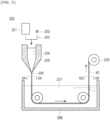
- Fig. 5 is a view schematically illustrating a method of manufacturing the filaments 40.
- Fig. 6A is a cross-sectional view taken along line 6A-6 A in Fig. 5
- Fig. 6B is a cross-sectional view taken along line 6B-6B in Fig. 5 .
- Each of the cross-sectional views schematically illustrates a part of a cross section orthogonal to the longitudinal axis of the filaments 40 in an enlarged manner.
- a manufacturing machine 200 for a filament 40 includes a supply unit 203 that supplies a raw material solution 201 of a resin composition constituting the filament 40 and a pore-forming material 202 for forming pores 41, a nozzle 205 that discharges a mixed liquid 204 of the raw material solution 201 and the pore-forming material 202 in stringlike, a tank 208 that stores a solvent 207 that allows passage of the raw material yarn 206 discharged from the nozzle 205, and a product roller 209 that winds up the filament 40 having a pore structure.
- the resin composition constituting the filament 40 is as described above. It is preferable that the pore-forming material 202 has a perfect spherical shape having a diameter within a range of 20 to 40 ⁇ m, and all diameters fall within ⁇ 10%.
- the pore-forming material 202 preferably has hardness capable of maintaining a perfect spherical shape during molding.
- the pore-forming material 202 is dissolved in a solvent 207 that does not dissolve the resin composition constituting the filament 40.
- the pore-forming material 202 is preferably formed of, for example, polymethyl methacrylate or polystyrene, and the solvent 207 used for dissolution is preferably, for example, tetrahydrofuran, chloroform, or the like.
- the shape of the nozzle 205 outlet and the discharge pressure for discharging the mixed liquid 204 is adjusted so that the pore-forming material 202 mixed in the raw material solution 201 comes into uniform contact with each other.
- the tank 208 is filled with a solvent 207 for dissolving only the pore-forming material 202.
- the inner diameter of the nozzle 205 defines the outer diameter of the filament 40, but the inner diameter of the nozzle 205 is desirably an integral multiple of the outer diameter of the pore-forming material 202 so that the pore-forming material 202 is uniformly disposed in the filament 40.
- the pore-forming materials 202 mixed in the raw material solution 201 are uniformly in contact with each other. While the raw material yarn 206 is moved in the solvent 207 in the tank 208, only the pore-forming material 202 is gradually dissolved and removed from the raw material yarn 206. As illustrated in Fig. 6B , when the raw material yarn 206 is pulled up from the solvent 207 in the tank 208, all the pore-forming materials 202 are dissolved and removed. As a result, the filament 40 of the porous body having the pore structure in which the plurality of pores 41 communicate with each other and are arranged in an array is obtained.
- the cross section of the filament 40 may not be circular, and may be a square or a rectangle in which one side is an integral multiple of the outer diameter of the pore-forming material 202.
- the filament 40 may be finished by polishing or cutting the surface of the extrusion-molded filament.
- the flow diverter stent 11 of the present embodiment is one of medical indwelling objects indwelled in the biological lumen, and includes the main body part 20 and the filaments 40 made of a non-biodegradable material combined with the main body part 20.
- the filaments 40 are a porous bodies having a large number of pores 41 possessing a diameter in a range of 20 to 40 um, the pores 41 all having a diameter falling within ⁇ 10%, arranged side by side, and each of the pores 41 communicating with at least three of the other pores 41.
- the characteristic pore structure of the filaments 40 allows the inner part of each filament 40 capture a large number of M1 macrophages (that promote inflammatory reaction) among macrophages in the blood, and as a result, the blood outside the filaments 40 (around the stent 11) has a high proportion of M2 macrophages (that promote healing).
- This polarization of macrophages has the effect of shortening the time period required for tissue repair (neointima formation) through the inflammatory phase ⁇ the proliferative phase ⁇ the maturation phase.
- the time period until complete occlusion of the aneurysm 100 or endothelialization of the entrance part of the aneurysm 100 is shortened.
- the filament 40 is made of a non-biodegradable material, there is no possibility that the material is decomposed and exfoliated, flows out into the blood vessel, and occludes the periphery. Therefore, promoting the healing reaction by controlling the phenotype of macrophages makes it possible to provide a stent 11 that is capable of shortening the time period required to complete occlusion of the aneurysm 100 and endothelialization of the entrance part of the aneurysm 100.
- All of the pores 41 preferably have a substantially uniform inner diameter such that any variation in the inner diameter of a pore is within ⁇ 10%. With this configuration, the pore structure of the filaments 40 becomes uniform, and the action of shortening the period required for tissue repair (neointima formation) can be reliably exerted.
- the main body part 20 is composed of the first wire 21 made of metal, and the filaments 40 that are combined on the inner surface side or the outer surface side of the main body part 20 or in the main body part 20.
- the main body part 20 has a braided body including a first wire 21 made of metal, and the filaments 40 are interwoven into the braided structure of the main body part 20. With this configuration, the skeleton of the stent 11 can be easily configured by the first wire 21 of the metal wire.
- second wires 22 made of metal having a diameter smaller than that of the first wire 21 is further combined with the first wire 21.
- the gap between the first wires 21 can be closed by the second wires 22, and the blood flow from the parent blood vessel 101 side to the aneurysm 100 side is blocked. Meanwhile, blood flow is secured in the stent 11.
- the filaments 40 are interwoven with the second wire 22. With this configuration, the filament 40 can be easily combined in the main body part 20.
- the resin composition constituting the filaments 40 is selected from polyolefin, polyethylene, polyolefin elastomer, ethylene-octene copolymer, polyethylene terephthalate, nylon, an amide-based polymer, a block copolymer, a polyether block amide copolymer, and polypropylene.
- the flexible filaments 40 made of a non-biodegradable material can be obtained.
- the stent 11 can be indwelled in the parent blood vessel 101 without impairing the operability of the stent and the followability to the blood vessel wall, and after the indwelling, the filaments 40 of the porous structure promotes a healing reaction and can achieve early endothelialization.
- the medical indwelling object of the present invention is applied to the embolic material 12 indwelled in the aneurysm 100 in order to close the inflow port from the parent blood vessel 101 to the aneurysm 100.
- Fig. 7 is a view schematically illustrating a state in which the embolic material 12 as the medical indwelling object is indwelled in the aneurysm 100
- Fig. 8 is an enlarged view illustrating a main part of the embolic material 12.
- One known method for treating the cerebrovascular aneurysm 100 involves embolization by a coil.
- it is necessary to arrange as many coils as needed to fill the volume of the aneurysm 100, which increases the operation time.
- the coil disposed in the aneurysm 100 spills over to the parent blood vessel 101.
- thrombose the aneurysm 100 since the aneurysm 100 may rupture until it thromboses, it is desirable to block blood flow between the aneurysm 100 and the parent blood vessel 101.
- the medical indwelling object of the present embodiment is a substantially spherical embolic material 12 that blocks the blood flow between the inside and the outside, is disposed in the aneurysm 100 in a compressed state, self-expands so as to return to the original substantially spherical shape by being released from the compressed state, and is suitable for constituting the embolic material 12 that is indwelled in the aneurysm 100 and used to close the inflow port from the parent blood vessel 101 to the aneurysm 100.
- the embolic material 12 is one of medical indwelling objects indwelled in the biological lumen, and includes a main body part 20 and filaments 40 made of a non-biodegradable material combined with the main body part 20.
- the main body part 20 is configured by braiding the first wire 21 made of metal, and the filaments 40 are combined in the main body part 20 as a part of the braided wire of the main body part 20.
- the first wire 21 may be further combined with the second wire 22 made of metal having a diameter smaller than that of the first wire 21.
- the gap between the first wires 21 can be closed by the second wire 22, and the blood flow from the parent blood vessel 101 side to the aneurysm 100 side can be blocked.
- the filaments 40 are the same as the filaments 40 of the first embodiment (see Fig. 3 and Fig. 4 ).
- the filaments 40 are composed of a porous body that includes a large number of pores 41 having a diameter within a range of 20 to 40 um, all the pores 41 having a diameter falling within ⁇ 10%, arranged side by side, and each of the pores 41 excluding the pores exposed on the outer surface of the filament 40 communicates with at least three to twelve other pores 41. Particularly preferably, each of the pores communicates with the other 6 or 12 pores 41 except for the pores near the surface of the filaments 40.
- the embolic material 12 of the second embodiment configured as described above has the same action and effect as those of the flow diverter stent 11 of the first embodiment. That is, according to the embolic material 12, the characteristic pore structure of the filaments 40 causes, the inner part of the filaments 40 to capture a large number of M1 macrophages (that promote inflammatory reaction) among macrophages in the blood, and as a result, the blood outside the filament 40 (around the embolic material 12) has a high proportion of M2 macrophages (which promote healing). This polarization of macrophages has the effect of shortening the time period required for tissue repair (neointima formation) through the inflammatory phase ⁇ the proliferative phase ⁇ the maturation phase.
- the period until complete occlusion of the aneurysm 100 or endothelialization of the entrance part of the aneurysm 100 is shortened.
- the filaments 40 are made of a non-biodegradable material, there is no possibility that the material is decomposed and exfoliated, flows out into the blood vessel, and occludes the periphery. Therefore, it is possible to provide the embolic material 12 capable of shortening the period until complete occlusion of the aneurysm 100 and endothelialization of the entrance part of the aneurysm 100 by promoting the healing reaction by controlling the phenotype of macrophages.
- the present invention is not limited to this case.
- the filaments 40 and a filament-shaped body made of another resin or metal are twisted to form a twisted wire, and the twisted wire is combined with the main body part 20 to form a medical indwelling object.
- Stent-graft indwelling technique is a way for supporting and indwelling a graft that reinforces a blood vessel wall from the inside by a stent to prevent rupture of the aneurysm 100.
- the graft is an artificial blood vessel interwoven with water-repellent fibers.
- the flow diverter stent 11 of the first embodiment can be used as a stent graft since it can prevent the flow of liquid between the inside and the outside. In this case, since a graft as a fiber layer is unnecessary, a stent graft having a small diameter and high flexibility can be obtained. As a result, the stent graft can also be used in thin blood vessels.
Landscapes
- Health & Medical Sciences (AREA)
- Life Sciences & Earth Sciences (AREA)
- Surgery (AREA)
- Biomedical Technology (AREA)
- Engineering & Computer Science (AREA)
- Veterinary Medicine (AREA)
- Animal Behavior & Ethology (AREA)
- Vascular Medicine (AREA)
- Public Health (AREA)
- Heart & Thoracic Surgery (AREA)
- General Health & Medical Sciences (AREA)
- Medical Informatics (AREA)
- Molecular Biology (AREA)
- Nuclear Medicine, Radiotherapy & Molecular Imaging (AREA)
- Reproductive Health (AREA)
- Neurosurgery (AREA)
- Cardiology (AREA)
- Oral & Maxillofacial Surgery (AREA)
- Transplantation (AREA)
- Prostheses (AREA)
- Surgical Instruments (AREA)
- Materials For Medical Uses (AREA)
Abstract
Description
- The present invention generally relates to a medical indwelling object indwelled in a biological lumen.
- For vascular diseases such as cerebral aneurysm, pulmonary aneurysm, and renal aneurysm, a procedure for preventing burst of the aneurysm by filling and occluding a metal coil is widely performed. On the other hand, as a new procedure, a method is performed in which a tubular body (flow diverter stent) obtained by interweaving a metal wire (particularly, nickel titanium) is indwelled in a parent blood vessel of the aneurysm to block and stagnate the blood flow into the aneurysm, and the blood in the aneurysm is thrombosed and organized. In addition, a method of interweaving a metal wire into a basket shape, indwelling the basket in an aneurysm, and similarly promoting organization is also performed.
- A vascular graft according to Patent Literature 1 below is configured to occlude a blood vessel system. This vascular graft creates a capillary effect inside it that allows blood to be carried through the vascular graft and coagulate within the vascular graft.
- Patent Literature 1:
JP 2018-502657 T - However, the vascular graft of the Patent Literature 1 merely considers that blood components are absorbed and cells enter, and may merely promote thrombus formation and an inflammatory reaction.
- When a medical indwelling object is indwelled in a blood vessel, a patient indwelled with the indwelling product needs to take an antiplatelet drug or an anticoagulant for a long period of time. This is because there is a risk that the surface of the indwelling object becomes a starting point of thrombus formation. Therefore, early acquisition of a state in which the surface of the indwelling object is covered with vascular endothelial cells, that is, early endothelialization is required.
- The present invention has been made to solve the problems associated with the prior art, and it is an object of the present invention to provide a medical indwelling object capable of shortening a period until complete occlusion of an aneurysm and endothelialization of an entrance part of the aneurysm.
- The present invention for achieving the above object is a medical indwelling object indwelled in a biological lumen, and the medical indwelling object includes a main body part and a filament made of a non-biodegradable material combined with the main body part. The filament is a porous body having a large number of pores in the range of 20 to 40 um in diameter, the pores all having a diameter falling within ± 10%, arranged side by side, and each of the pores being communicated with at least the other three of the pores.
- According to the medical indwelling object according to the present invention, due to the pore structure of the filament, the inner part of the filament exerts an action including many M1 macrophages (pro-inflammatory reaction) among macrophages in the blood, and as a result, the blood around the filament has a relatively high ratio of M2 macrophages (pro-healing). Such polarization of macrophages shortens the time to complete occlusion of the aneurysm or endothelialization of the entrance part of the aneurysm. In addition,
- Since the filament is made of a non-biodegradable material, there is no possibility that the material is decomposed and exfoliated, flows into a blood vessel, and occludes the periphery. Therefore, it is possible to provide a medical indwelling object capable of shortening a period until complete occlusion of the aneurysm and endothelialization of the entrance part of the aneurysm.
-
-
Fig. 1 is a view schematically illustrating a state in which a flow diverter stent as a medical indwelling object is indwelled between a parent blood vessel and an aneurysm. -
Fig. 2A is a side view illustrating a main part of the flow diverter stent. -
Fig. 2B is an end view taken alongline 2B-2B inFig. 2A , schematically illustrating a combination form of the main body part and the filaments. -
Fig. 3 is a perspective view schematically illustrating a filament of a flow diverter stent. -
Fig. 4 is an enlarged view illustrating a part surrounded by areference numeral 4 inFig. 3 and illustrating a pore structure of the filament. -
Fig. 5 is a view schematically illustrating a method for manufacturing the filament. -
Fig. 6A is an enlarged cross-sectional view schematically illustrating a part of a cross section taken alongline 6A-6A inFig. 5 . -
Fig. 6B is an enlarged cross-sectional view schematically illustrating a part of a cross section taken alongline 6B-6B inFig. 5 . -
Fig. 7 is a view schematically illustrating a state in which an embolic material as a medical indwelling object is indwelled in an aneurysm. -
Fig. 8 is an enlarged view illustrating a main part of the embolic material. - Hereinafter, embodiments of the present invention and modifications thereof is described with reference to the accompanying drawings. The following description does not limit the technical scope or the significance of each term used in the claims. Furthermore, dimensional ratios of the drawings are exaggerated for illustration purpose and may differ from actual ratios.
- In the first embodiment, the medical indwelling object of the present invention is applied to the flow diverter stent 11 (stent 11) that blocks the blood flow between the
parent blood vessel 101 and theaneurysm 100. Theparent blood vessel 101 and theaneurysm 100 correspond to the biological lumen.Fig. 1 is a view schematically illustrating a state in which aflow diverter stent 11 as a medical indwelling object is indwelled between aparent blood vessel 101 and ananeurysm 100. InFig. 2A , the gap part is greatly exaggerated in order to easily grasp the mesh shape of theflow diverter stent 11. - As illustrated in
Fig. 1 , theflow diverter stent 11 is indwelled between theparent blood vessel 101 and theaneurysm 100, and is used to block the blood flow between theparent blood vessel 101 and theaneurysm 100. Theflow diverter stent 11 is a stent having self-expandability. Theflow diverter stent 11 is inserted and indwelled to a target site of theparent blood vessel 101 by a self-expanding stent delivery system (not illustrated). -
Fig. 2A is a side view illustrating a main part of theflow diverter stent 11, andFig. 2B is an end view taken alongline 2B-2B inFig. 2A , schematically illustrating a combination form of themain body part 20 and thefilaments 40.Fig. 3 is a perspective view schematically illustrating afilament 40 of theflow diverter stent 11, andFig. 4 is an enlarged view of a part surrounded byreference numeral 4 inFig. 3 , illustrating a pore structure of thefilament 40. - As illustrated in
Figs. 2A ,3 , and4 , theflow diverter stent 11 is an example of one of the medical indwelling objects indwelled in the biological lumen, and includes themain body part 20 andfilaments 40 made of a non-biodegradable material that is combined with themain body part 20. - Each
filament 40 is composed of a porous body having a large number ofpores 41 arranged side by side. Thepores 41 may have an inner diameter in the range of 20 to 40 um, and thepores 41 have a substantially uniform inner diameter, meaning any variation in the diameter of a pore falls within ± 10%. Each of thepores 41 communicates with at least threeother pores 41. Hereinafter, the configuration of theflow diverter stent 11 is described in detail. - As illustrated in
Fig. 2A , themain body part 20 is a stent having self-expandability, and is composed of a first wire(s) 21 made of metal. Thefirst wire 21 is braided in a mesh shape to form tubular stent struts. The metal used for thefirst wire 21 is preferably a biocompatible metal, and examples thereof include stainless steel, tantalum or a tantalum alloy, platinum or a platinum alloy, gold or a gold alloy, a cobalt base alloy such as a cobalt-chromium alloy, and a nickel-titanium alloy. Among them, a nickel-titanium alloy, which is a material having superelasticity, is most preferable in order to achieve self-expandability. In addition, precious metal plating (gold, platinum) for imparting X-ray contrast property may be applied after the shape of the stent is prepared. The diameter of thefirst wire 21 is not particularly limited, and is, for example, 100 um (micrometer). The tubular body composed of thefirst wire 21 of a relatively thick metal wire constitutes a framework as a self-expanding stent. - In the
main body part 20,second wires 22 made of metal having a diameter smaller than that of thefirst wire 21 are combined with thefirst wire 21. Thesecond wires 22 are braided at a finer pitch than the mesh of thefirst wire 21 so as to close the gap between thefirst wires 21, and is arranged inside the tubular mesh of thefirst wire 21. With this configuration, minute gaps between the first wire(s) 21 are blocked or closed by thesecond wires 22, thereby blocking (minimizing) blood flow from theparent blood vessel 101 side to theaneurysm 100 side. The metal used for thesecond wires 22 may be the same metal as the metal used for thefirst wire 21. The diameter of thesecond wires 22 is not particularly limited, and is, for example, 25 to 30 um. The tubular body composed of thefirst wire 21 and the tubular body composed of thesecond wires 22 are fixed by a third wire (not illustrated). As the third wire, for example, a metal having X-ray contrast property is used, and tungsten is particularly suitable. A plurality of third wires are provided so that a tubular body composed of thefirst wire 21 and a tubular body composed of thesecond wire 22 are sewn together in the axial direction. - The
filaments 40 can be combined on the inner surface side, the outer surface side of themain body part 20, or within themain body part 20. As illustrated inFigs. 2A and2B , in theflow diverter stent 11 of the first embodiment, thefilaments 40 are incorporated (interwoven) in the tubular body composed of thesecond wires 22 in a manner replacing a plurality of the second wires. - As such, the
filaments 40 may be combined into themain body part 20. The phrase "combined into or within themain body part 20" refers to a form in which thesecond wires 22 and thefilaments 40 are substantially on/in the same plane when viewed in a cross section, by weaving thesecond wires 22 into a mesh configuration and weaving thefilaments 40 at the same time, or by later inserting thefilaments 40 into the opening parts of themain body part 20. - In the
main body part 20, as described above, thesecond wires 22 are further combined with thefirst wire 21. Therefore, when thefilaments 40 are combined in themain body part 20, a part of thesecond wire 22 may be replaced with thefilaments 40. The replacing ratio can be appropriately set. - As a modification, the
filaments 40 may be braided in a mesh shape separately from themain body part 20 and housed in the lumen of themain body part 20. The mesh-shapedfilaments 40 are fixed to themain body part 20 at an appropriate position so as not to hinder the self-expandability of themain body part 20. The fixing method is not limited, but for example, thefilaments 40 may be wound around and fixed to thefirst wire 21 of themain body part 20 by a tungsten wire having X-ray contrast property. - In addition, as a second modification, the
filaments 40 formed in a mesh shape may be combined with the outer surface side of themain body part 20. In this embodiment, thefilaments 40 are braided in a mesh shape separately from themain body part 20, and the resulting mesh-shapedknitted filaments 40 are positioned to cover the outer peripheral surface of themain body part 20. The mesh-shapedfilaments 40 are fixed to themain body part 20 at an appropriate position so as not to hinder the self-expandability of themain body part 20. The fixing method is not limited, but thefilaments 40 may be wound around and fixed to thefirst wire 21 of themain body part 20 by the tungsten wire having the X-ray contrast property as described above. - The material constituting the
filaments 40 is preferably a non-biodegradable material and a flexible material. A metal or resin material can be applied as a constituent material of thefilaments 40, but a resin material is preferable from the viewpoint of manufacturing a pore structure to be described later. The material of the resin material needs to be a material that is not decomposed in the living body. Specifically, as the resin composition constituting thefilament 40, polyolefin, polyethylene, a polyolefin elastomer, an ethylene-octene copolymer, polyethylene terephthalate (PET), nylon, an amide-based polymer, a block copolymer, a polyether block amide copolymer (for example, PEBAX (registered trademark) manufactured by Arkema K.K.), and polypropylene are suitably used. - The diameter of the
filaments 40 is not particularly limited, but because thefilaments 40 are porous bodies in which each pore 41 is preferably connected to at least threeother pores 41, it is preferably that the diameter of thefilaments 40 is 60 to 120 um in relation to the inner diameter (20 to 40 µm) of thepores 41. - As shown in
Figs. 3 and4 , each of thefilaments 40 is a porous body having a large number ofpores 41 having an inner diameter in a range of 20 to 40 um, thepores 41 having a substantially uniform inner diameter such that any variation in the diameters of all pores fall within ± 10%, arranged side by side in an array, and each of thepores 41 being in communication with at least the other threepores 41.Fig. 4 illustrates an axis-orthogonal cross section of thefilaments 40 of the porous body having the above-described pore structure. The circle indicated byreference numeral 41 indicates a large number ofpores 41 having a diameter in the range of 20 to 40 µm, and any variation in the diameters of all thepores 41 falling within ± 10%. Each of thepores 41 is arranged side by side in an array in a close-packed state. Three ellipses indicated byreference numeral 42 in onepore 41 indicate communication pores 42 in whichadjacent pores 41 are in contact with each other and theadjacent pores 41 communicate with each other at a contact point. Furthermore, two ellipses denoted byreference numeral 42a in onecommunication pore 42 indicate acommunication pore 42a that can be seen further on the back side through thecommunication pore 42. - In order to obtain a uniform pore structure, it is preferable that all diameters of the
pores 41 fall within ± 10% of each other. - Each of the
pores 41 may communicate with threeother pores 41 to twelveother pores 41. Most preferably, eachpore 41 communicates with six or twelveother pores 41, except for thepores 41 exposed on the outer surface of thefilaments 40. In the present embodiment, as shown inFig. 4 , the pores communicate with three pores on the back side from the center, similarly communicate with three pores in front, and further communicate with six pores surrounding the side surface, so that the pores communicate with a total of twelve pores. In the present embodiment, substantially all thepores 41 communicate with at least the other threepores 41, but the number of the adjacentother pores 41 is limited for thepores 41 located on the outer surface of thefilaments 40, and thus a case where the number of the other pores communicating with each other is smaller than three is also acceptable. - The tissue repair process after indwelling of the
flow diverter stent 11 is similar to the healing process of a skin wound, passing through the inflammatory phase → the proliferative phase → the maturation phase, and then transformation into neointima, completing the healing process. Theporous filaments 40 of this embodiment having the above-described pore structure has the effect of shortening the period required for tissue repair (neointima formation) through the inflammatory phase → the proliferative phase → the maturation phase. The mechanism behind this is thought to be that the pore structure of thefilaments 40 causes the inner part of thefilaments 40 to capture many M1 macrophages (pro-inflammatory reaction) among the macrophages in the blood, so that the macrophages around the filaments 40 (around the flow diverter stent 11) are polarized into a state of a high ratio of M2 macrophages (pro-healing). M1 macrophages produce pro-inflammatory cytokines and M2 macrophages produce antiinflammatory cytokines. It is considered that complete occlusion of theaneurysm 100, healing of the entrance part of theaneurysm 100, and endothelialization are completed early by the polarization of macrophages. Such an action is particularly remarkable when the diameter of thepores 41 is in therange 20 to 40 µm. - At present, the detailed mechanism by which the polarization of macrophages occurs in a specific pore structure has not been clarified clearly.
- In the
flow diverter stent 11 of the present embodiment configured as described above, the pore structure of thefilament 40 promotes not only enhancement of the inflammatory reaction but also promotion of the healing reaction with respect to the occlusion of theaneurysm 100. Therefore, it is possible to reduce the possibility that the period until complete occlusion due to continuation of the inflammatory reaction is prolonged or endothelialization becomes insufficient. - In addition, since the
filaments 40 have both a healing promoting function and flexibility, it can be indwelled in theparent blood vessel 101 without impairing the operability of theflow diverter stent 11 and the followability to the blood vessel wall. After indwelling, thefilaments 40 of the porous structure can promote a healing reaction and achieve early endothelialization. Since thefilament 40 is flexible, the self-expandability of themain body part 20 can be favorably maintained. - In addition, since the
filament 40 is configured from a non-biodegradable material, a situation in which the material is decomposed and flows into the blood stream to occlude the periphery does not occur. -
Fig. 5 is a view schematically illustrating a method of manufacturing thefilaments 40.Fig. 6A is a cross-sectional view taken alongline 6A-6 A inFig. 5 , andFig. 6B is a cross-sectional view taken alongline 6B-6B inFig. 5 . Each of the cross-sectional views schematically illustrates a part of a cross section orthogonal to the longitudinal axis of thefilaments 40 in an enlarged manner. - As shown in
Fig. 5 , amanufacturing machine 200 for afilament 40 includes asupply unit 203 that supplies araw material solution 201 of a resin composition constituting thefilament 40 and a pore-formingmaterial 202 for formingpores 41, anozzle 205 that discharges amixed liquid 204 of theraw material solution 201 and the pore-formingmaterial 202 in stringlike, atank 208 that stores a solvent 207 that allows passage of theraw material yarn 206 discharged from thenozzle 205, and aproduct roller 209 that winds up thefilament 40 having a pore structure. - The resin composition constituting the
filament 40 is as described above. It is preferable that the pore-formingmaterial 202 has a perfect spherical shape having a diameter within a range of 20 to 40 µm, and all diameters fall within ± 10%. The pore-formingmaterial 202 preferably has hardness capable of maintaining a perfect spherical shape during molding. The pore-formingmaterial 202 is dissolved in a solvent 207 that does not dissolve the resin composition constituting thefilament 40. The pore-formingmaterial 202 is preferably formed of, for example, polymethyl methacrylate or polystyrene, and the solvent 207 used for dissolution is preferably, for example, tetrahydrofuran, chloroform, or the like. The shape of thenozzle 205 outlet and the discharge pressure for discharging themixed liquid 204 is adjusted so that the pore-formingmaterial 202 mixed in theraw material solution 201 comes into uniform contact with each other. - The
tank 208 is filled with a solvent 207 for dissolving only the pore-formingmaterial 202. The inner diameter of thenozzle 205 defines the outer diameter of thefilament 40, but the inner diameter of thenozzle 205 is desirably an integral multiple of the outer diameter of the pore-formingmaterial 202 so that the pore-formingmaterial 202 is uniformly disposed in thefilament 40. - As illustrated in
Fig. 6A , in theraw material yarn 206 discharged from thenozzle 205, the pore-formingmaterials 202 mixed in theraw material solution 201 are uniformly in contact with each other. While theraw material yarn 206 is moved in the solvent 207 in thetank 208, only the pore-formingmaterial 202 is gradually dissolved and removed from theraw material yarn 206. As illustrated inFig. 6B , when theraw material yarn 206 is pulled up from the solvent 207 in thetank 208, all the pore-formingmaterials 202 are dissolved and removed. As a result, thefilament 40 of the porous body having the pore structure in which the plurality ofpores 41 communicate with each other and are arranged in an array is obtained. - In order to form the
pores 41 without gaps as much as possible in the above-described manufacturing process, the cross section of thefilament 40 may not be circular, and may be a square or a rectangle in which one side is an integral multiple of the outer diameter of the pore-formingmaterial 202. When the pore-formingmaterial 202 is not disposed on the outer surface of the manufacturedfilament 40 and thepores 41 are not formed, thefilament 40 may be finished by polishing or cutting the surface of the extrusion-molded filament. - As described above, the
flow diverter stent 11 of the present embodiment is one of medical indwelling objects indwelled in the biological lumen, and includes themain body part 20 and thefilaments 40 made of a non-biodegradable material combined with themain body part 20. Thefilaments 40 are a porous bodies having a large number ofpores 41 possessing a diameter in a range of 20 to 40 um, thepores 41 all having a diameter falling within ± 10%, arranged side by side, and each of thepores 41 communicating with at least three of the other pores 41. - According to the
stent 11 configured in this manner, the characteristic pore structure of thefilaments 40 allows the inner part of eachfilament 40 capture a large number of M1 macrophages (that promote inflammatory reaction) among macrophages in the blood, and as a result, the blood outside the filaments 40 (around the stent 11) has a high proportion of M2 macrophages (that promote healing). This polarization of macrophages has the effect of shortening the time period required for tissue repair (neointima formation) through the inflammatory phase → the proliferative phase → the maturation phase. As a result, the time period until complete occlusion of theaneurysm 100 or endothelialization of the entrance part of theaneurysm 100 is shortened. Moreover, since thefilament 40 is made of a non-biodegradable material, there is no possibility that the material is decomposed and exfoliated, flows out into the blood vessel, and occludes the periphery. Therefore, promoting the healing reaction by controlling the phenotype of macrophages makes it possible to provide astent 11 that is capable of shortening the time period required to complete occlusion of theaneurysm 100 and endothelialization of the entrance part of theaneurysm 100. - All of the
pores 41 preferably have a substantially uniform inner diameter such that any variation in the inner diameter of a pore is within ± 10%. With this configuration, the pore structure of thefilaments 40 becomes uniform, and the action of shortening the period required for tissue repair (neointima formation) can be reliably exerted. - The
main body part 20 is composed of thefirst wire 21 made of metal, and thefilaments 40 that are combined on the inner surface side or the outer surface side of themain body part 20 or in themain body part 20. With this configuration, since thefilaments 40 come into contact with or come close to the inner wall surface of the biological lumen, the action of shortening the period required for tissue repair (neointima formation) can be more reliably realized. - The
main body part 20 has a braided body including afirst wire 21 made of metal, and thefilaments 40 are interwoven into the braided structure of themain body part 20. With this configuration, the skeleton of thestent 11 can be easily configured by thefirst wire 21 of the metal wire. - In the
main body part 20,second wires 22 made of metal having a diameter smaller than that of thefirst wire 21 is further combined with thefirst wire 21. With this configuration, the gap between thefirst wires 21 can be closed by thesecond wires 22, and the blood flow from theparent blood vessel 101 side to theaneurysm 100 side is blocked. Meanwhile, blood flow is secured in thestent 11. By blocking theaneurysm 100 from theparent blood vessel 101, it is possible to thrombose theaneurysm 100 at an early stage and prevent rupture. - The
filaments 40 are interwoven with thesecond wire 22. With this configuration, thefilament 40 can be easily combined in themain body part 20. - The resin composition constituting the
filaments 40 is selected from polyolefin, polyethylene, polyolefin elastomer, ethylene-octene copolymer, polyethylene terephthalate, nylon, an amide-based polymer, a block copolymer, a polyether block amide copolymer, and polypropylene. With this configuration, theflexible filaments 40 made of a non-biodegradable material can be obtained. As a result, thestent 11 can be indwelled in theparent blood vessel 101 without impairing the operability of the stent and the followability to the blood vessel wall, and after the indwelling, thefilaments 40 of the porous structure promotes a healing reaction and can achieve early endothelialization. - In the second embodiment, the medical indwelling object of the present invention is applied to the
embolic material 12 indwelled in theaneurysm 100 in order to close the inflow port from theparent blood vessel 101 to theaneurysm 100.Fig. 7 is a view schematically illustrating a state in which theembolic material 12 as the medical indwelling object is indwelled in theaneurysm 100, andFig. 8 is an enlarged view illustrating a main part of theembolic material 12. - One known method for treating the
cerebrovascular aneurysm 100 involves embolization by a coil. However, in order to pack the coils into theaneurysm 100, it is necessary to arrange as many coils as needed to fill the volume of theaneurysm 100, which increases the operation time. In addition, when the entrance between theaneurysm 100 and theparent blood vessel 101 is large, there is a possibility that the coil disposed in theaneurysm 100 spills over to theparent blood vessel 101. Furthermore, since a small amount of blood flow occurs between theaneurysm 100 and theparent blood vessel 101, it takes a relatively long time to thrombose theaneurysm 100. Since theaneurysm 100 may rupture until it thromboses, it is desirable to block blood flow between theaneurysm 100 and theparent blood vessel 101. - Therefore, the medical indwelling object of the present embodiment is a substantially spherical
embolic material 12 that blocks the blood flow between the inside and the outside, is disposed in theaneurysm 100 in a compressed state, self-expands so as to return to the original substantially spherical shape by being released from the compressed state, and is suitable for constituting theembolic material 12 that is indwelled in theaneurysm 100 and used to close the inflow port from theparent blood vessel 101 to theaneurysm 100. - The
embolic material 12 is one of medical indwelling objects indwelled in the biological lumen, and includes amain body part 20 andfilaments 40 made of a non-biodegradable material combined with themain body part 20. - Like the
main body part 20 of theflow diverter stent 11 described above, themain body part 20 is configured by braiding thefirst wire 21 made of metal, and thefilaments 40 are combined in themain body part 20 as a part of the braided wire of themain body part 20. - With this configuration, since the
filament 40 comes into contact with or comes close to the inner wall surface of the biological lumen, the action of shortening the period required for tissue repair (neointima formation) can be more reliably exerted. - Similar to the first embodiment, in the
main body part 20, thefirst wire 21 may be further combined with thesecond wire 22 made of metal having a diameter smaller than that of thefirst wire 21. With this configuration, the gap between thefirst wires 21 can be closed by thesecond wire 22, and the blood flow from theparent blood vessel 101 side to theaneurysm 100 side can be blocked. By blocking theaneurysm 100 from theparent blood vessel 101, it is possible to thrombose theaneurysm 100 at an early stage and prevent rupture. - The
filaments 40 are the same as thefilaments 40 of the first embodiment (seeFig. 3 andFig. 4 ). Thefilaments 40 are composed of a porous body that includes a large number ofpores 41 having a diameter within a range of 20 to 40 um, all thepores 41 having a diameter falling within ± 10%, arranged side by side, and each of thepores 41 excluding the pores exposed on the outer surface of thefilament 40 communicates with at least three to twelveother pores 41. Particularly preferably, each of the pores communicates with the other 6 or 12pores 41 except for the pores near the surface of thefilaments 40. - The
embolic material 12 of the second embodiment configured as described above has the same action and effect as those of theflow diverter stent 11 of the first embodiment. That is, according to theembolic material 12, the characteristic pore structure of thefilaments 40 causes, the inner part of thefilaments 40 to capture a large number of M1 macrophages (that promote inflammatory reaction) among macrophages in the blood, and as a result, the blood outside the filament 40 (around the embolic material 12) has a high proportion of M2 macrophages (which promote healing). This polarization of macrophages has the effect of shortening the time period required for tissue repair (neointima formation) through the inflammatory phase → the proliferative phase → the maturation phase. As a result, the period until complete occlusion of theaneurysm 100 or endothelialization of the entrance part of theaneurysm 100 is shortened. Moreover, since thefilaments 40 are made of a non-biodegradable material, there is no possibility that the material is decomposed and exfoliated, flows out into the blood vessel, and occludes the periphery. Therefore, it is possible to provide theembolic material 12 capable of shortening the period until complete occlusion of theaneurysm 100 and endothelialization of the entrance part of theaneurysm 100 by promoting the healing reaction by controlling the phenotype of macrophages. - Although the medical indwelling object according to the present invention has been described through the first embodiment and the second embodiment, the present invention is not limited to these cases, and can be appropriately changed based on the description of the claims.
- Although the embodiment in which only the
filaments 40 of the porous structure are combined with themain body part 20 is described, the present invention is not limited to this case. For example, thefilaments 40 and a filament-shaped body made of another resin or metal are twisted to form a twisted wire, and the twisted wire is combined with themain body part 20 to form a medical indwelling object. - Further, it can be modified as follows. As one of the methods for treating the
aortic aneurysm 100, stent-graft indwelling technique is known. Stent-graft indwelling technique is a way for supporting and indwelling a graft that reinforces a blood vessel wall from the inside by a stent to prevent rupture of theaneurysm 100. The graft is an artificial blood vessel interwoven with water-repellent fibers. Theflow diverter stent 11 of the first embodiment can be used as a stent graft since it can prevent the flow of liquid between the inside and the outside. In this case, since a graft as a fiber layer is unnecessary, a stent graft having a small diameter and high flexibility can be obtained. As a result, the stent graft can also be used in thin blood vessels. -
- 11
- Flow diverter stent (stent, medical indwelling object)
- 12
- Embolic material (medical indwelling object)
- 20
- Main body part
- 21
- First wire
- 22
- Second wire
- 40
- Filament
- 41
- Pore
- 42
- Communication pore
- 42a
- Communication pore
- 100
- Aneurysm (biological lumen)
- 101
- Parent blood vessel (biological lumen)
- 200
- Manufacturing machine
- 201
- Raw material solution
- 202
- Pore-forming material
- 203
- Supply unit
- 204
- Mixed liquid
- 205
- Nozzle
- 206
- Raw material yarn
- 207
- Solvent that dissolves only pore-forming material
- 208
- Tank
- 209
- Product roller
Claims (8)
- A medical indwelling object configured to be indwelled in a biological lumen, comprising:a main body part,a filament made of a non-biodegradable material combined with the main body part,the filament being a porous body having a plurality of pores each having a diameter in a range of 20 to 40 um, the pores all having a diameter such that any variation in the diameter is within ± 10%, the pores being arranged side by side, and each of the pores being in communication with at least three others of the pores.
- The medical indwelling object according to claim 1, wherein the main body part is comprised of a first wire made of metal, and
the filament is positioned on an inner surface side of the main body part or an outer surface side of the main body part, or in the main body part. - The medical indwelling object according to claim 1, wherein the main body part includes a braided body including the first wire made of metal, and
the filament is interwoven into a braided structure of the main body part. - The medical indwelling object according to claim 2 or 3, wherein the main body part is formed by further combining a second wire made of metal having a diameter smaller than that of the first wire with the first wire.
- The medical indwelling object according to claim 4, wherein the filament is interwoven together with the second wire.
- The medical indwelling object according to claim 1, wherein a resin composition constituting the filament is selected from polyolefin, polyethylene, polyolefin elastomer, ethylene-octene copolymer, polyethylene terephthalate, nylon, an amide-based polymer, a block copolymer, a polyether block amide copolymer, and polypropylene.
- The medical indwelling object according to claim 1, wherein the medical indwelling object is a flow diverter stent that blocks blood flow between the parent blood vessel and the aneurysm.
- The medical indwelling object according to claim 1, wherein the medical indwelling object is an embolic material indwelled in the aneurysm in order to close an inflow port from the parent blood vessel to the aneurysm.
Applications Claiming Priority (1)
| Application Number | Priority Date | Filing Date | Title |
|---|---|---|---|
| PCT/JP2022/017024 WO2023195039A1 (en) | 2022-04-04 | 2022-04-04 | Indwelling medical object |
Publications (2)
| Publication Number | Publication Date |
|---|---|
| EP4494571A1 true EP4494571A1 (en) | 2025-01-22 |
| EP4494571A4 EP4494571A4 (en) | 2025-05-21 |
Family
ID=88242604
Family Applications (1)
| Application Number | Title | Priority Date | Filing Date |
|---|---|---|---|
| EP22936442.7A Pending EP4494571A4 (en) | 2022-04-04 | 2022-04-04 | RESIDENT MEDICAL OBJECT |
Country Status (4)
| Country | Link |
|---|---|
| US (1) | US20250009356A1 (en) |
| EP (1) | EP4494571A4 (en) |
| JP (1) | JPWO2023195039A1 (en) |
| WO (1) | WO2023195039A1 (en) |
Family Cites Families (9)
| Publication number | Priority date | Publication date | Assignee | Title |
|---|---|---|---|---|
| US6240616B1 (en) * | 1997-04-15 | 2001-06-05 | Advanced Cardiovascular Systems, Inc. | Method of manufacturing a medicated porous metal prosthesis |
| US6702848B1 (en) * | 1999-07-20 | 2004-03-09 | Peter Paul Zilla | Foam-type vascular prosthesis with well-defined anclio-permissive open porosity |
| US20050043585A1 (en) * | 2003-01-03 | 2005-02-24 | Arindam Datta | Reticulated elastomeric matrices, their manufacture and use in implantable devices |
| WO2008098923A2 (en) * | 2007-02-13 | 2008-08-21 | Cinvention Ag | Porous stent |
| JP4526589B2 (en) * | 2009-04-14 | 2010-08-18 | テルモ株式会社 | Covered stent |
| JP6763864B2 (en) | 2015-01-20 | 2020-09-30 | ニューロガミ メディカル インコーポレイテッド | Micrografts and usage for the treatment of intracranial aneurysms |
| US10478194B2 (en) * | 2015-09-23 | 2019-11-19 | Covidien Lp | Occlusive devices |
| WO2018181179A1 (en) * | 2017-03-30 | 2018-10-04 | テルモ株式会社 | Medical instrument with hydrophilic member and hydrophobic member laminated |
| WO2019212894A1 (en) * | 2018-05-02 | 2019-11-07 | Conformal Medical, Inc. | Devices and methods for excluding the left atrial appendage |
-
2022
- 2022-04-04 JP JP2024513571A patent/JPWO2023195039A1/ja active Pending
- 2022-04-04 EP EP22936442.7A patent/EP4494571A4/en active Pending
- 2022-04-04 WO PCT/JP2022/017024 patent/WO2023195039A1/en not_active Ceased
-
2024
- 2024-09-26 US US18/897,579 patent/US20250009356A1/en active Pending
Also Published As
| Publication number | Publication date |
|---|---|
| US20250009356A1 (en) | 2025-01-09 |
| EP4494571A4 (en) | 2025-05-21 |
| WO2023195039A1 (en) | 2023-10-12 |
| JPWO2023195039A1 (en) | 2023-10-12 |
Similar Documents
| Publication | Publication Date | Title |
|---|---|---|
| CN101969883B (en) | Stent and method of making a stent | |
| US8409242B2 (en) | Embolic filters with controlled pore size | |
| CA2828136C (en) | Implant comprising a non-woven fabric | |
| EP2990011B1 (en) | Multi-strand implant with enhanced radiopacity | |
| DE69919355T2 (en) | WATER SOLUBLE COATING FOR BIOACTIVE VASO OCCLUSION DEVICE | |
| JP2013059643A (en) | Graft and stent graft having radiopaque beading | |
| CN109640840B (en) | Implant with detachment mechanism | |
| WO2005072651A2 (en) | Medical devices comprising ceramic fibres | |
| CN113271889B (en) | Medical device, medical kit and manufacturing method for introduction into a hollow body organ | |
| EP3256059A1 (en) | Vascular occlusion devices | |
| CN114269264A (en) | Medical kit and medical system for treating aneurysm | |
| CN114269265A (en) | Medical kit for treating aneurysms, method of manufacture, and medical system for treating aneurysms | |
| EP3565510A1 (en) | Multilayer luminal endoprosthesis assembly and manufacturing method | |
| WO2019175341A1 (en) | "a stent, and a method for the treatment of an aneurysm in an intracranial vessel" | |
| JP2018007802A (en) | Lumen stent and manufacturing method thereof | |
| US20250009356A1 (en) | Medical indwelling object | |
| CN116056670A (en) | Multi-layer folded blood flow guiding device | |
| CN118369073A (en) | Implants for treating aneurysms in the bifurcation region | |
| EP4013359B1 (en) | Stent braid pattern with enhanced radiopacity | |
| JP3206584U (en) | Lumen stent | |
| CN212755993U (en) | Covered stent | |
| CN115414164B (en) | Blood flow guiding dense net support | |
| US20230301806A1 (en) | Implant For Treating Aneurysms | |
| CN212913284U (en) | a bracket | |
| CN209770600U (en) | Implant intervention instrument |
Legal Events
| Date | Code | Title | Description |
|---|---|---|---|
| STAA | Information on the status of an ep patent application or granted ep patent |
Free format text: STATUS: THE INTERNATIONAL PUBLICATION HAS BEEN MADE |
|
| PUAI | Public reference made under article 153(3) epc to a published international application that has entered the european phase |
Free format text: ORIGINAL CODE: 0009012 |
|
| STAA | Information on the status of an ep patent application or granted ep patent |
Free format text: STATUS: REQUEST FOR EXAMINATION WAS MADE |
|
| 17P | Request for examination filed |
Effective date: 20241017 |
|
| AK | Designated contracting states |
Kind code of ref document: A1 Designated state(s): AL AT BE BG CH CY CZ DE DK EE ES FI FR GB GR HR HU IE IS IT LI LT LU LV MC MK MT NL NO PL PT RO RS SE SI SK SM TR |
|
| A4 | Supplementary search report drawn up and despatched |
Effective date: 20250423 |
|
| RIC1 | Information provided on ipc code assigned before grant |
Ipc: A61B 17/00 20060101AFI20250415BHEP |
|
| DAV | Request for validation of the european patent (deleted) | ||
| DAX | Request for extension of the european patent (deleted) |