EP4494495A1 - Aerosol-generating device with filtering system - Google Patents
Aerosol-generating device with filtering system Download PDFInfo
- Publication number
- EP4494495A1 EP4494495A1 EP23186518.9A EP23186518A EP4494495A1 EP 4494495 A1 EP4494495 A1 EP 4494495A1 EP 23186518 A EP23186518 A EP 23186518A EP 4494495 A1 EP4494495 A1 EP 4494495A1
- Authority
- EP
- European Patent Office
- Prior art keywords
- aerosol
- filtering
- porous partition
- generating device
- liquid
- Prior art date
- Legal status (The legal status is an assumption and is not a legal conclusion. Google has not performed a legal analysis and makes no representation as to the accuracy of the status listed.)
- Withdrawn
Links
Images



Classifications
-
- A—HUMAN NECESSITIES
- A24—TOBACCO; CIGARS; CIGARETTES; SIMULATED SMOKING DEVICES; SMOKERS' REQUISITES
- A24F—SMOKERS' REQUISITES; MATCH BOXES; SIMULATED SMOKING DEVICES
- A24F40/00—Electrically operated smoking devices; Component parts thereof; Manufacture thereof; Maintenance or testing thereof; Charging means specially adapted therefor
- A24F40/40—Constructional details, e.g. connection of cartridges and battery parts
-
- A—HUMAN NECESSITIES
- A24—TOBACCO; CIGARS; CIGARETTES; SIMULATED SMOKING DEVICES; SMOKERS' REQUISITES
- A24F—SMOKERS' REQUISITES; MATCH BOXES; SIMULATED SMOKING DEVICES
- A24F40/00—Electrically operated smoking devices; Component parts thereof; Manufacture thereof; Maintenance or testing thereof; Charging means specially adapted therefor
- A24F40/10—Devices using liquid inhalable precursors
-
- A—HUMAN NECESSITIES
- A24—TOBACCO; CIGARS; CIGARETTES; SIMULATED SMOKING DEVICES; SMOKERS' REQUISITES
- A24F—SMOKERS' REQUISITES; MATCH BOXES; SIMULATED SMOKING DEVICES
- A24F40/00—Electrically operated smoking devices; Component parts thereof; Manufacture thereof; Maintenance or testing thereof; Charging means specially adapted therefor
- A24F40/40—Constructional details, e.g. connection of cartridges and battery parts
- A24F40/48—Fluid transfer means, e.g. pumps
- A24F40/485—Valves; Apertures
Definitions
- the invention relates to an aerosol-generating device which is provided with a filtering system.
- Aerosol-generating devices are designed for users thereof to inhale air that is loaded with aerosol.
- each device comprises an atomizing system that produces liquid droplets from an aerosol precursor, and the droplets are driven by an airflow to a mouthpiece of the aerosol-generating device.
- the atomizing system is based on a heater, the aerosol precursor is heated and vaporized by the heater, and the precursor vapor in the airflow then condensates into liquid droplets when cooling down in the path from the heater to the mouthpiece. With such operation, the precursor is heated but not cooked.
- US 2022/0015433 A1 discloses using an outlet filter which is arranged in the airflow path of an aerosol-generating device between the atomizing system and the mouthpiece, for blocking the precursor droplets that have a size above a predetermined limit.
- Such filter suppresses large precursor droplets caused by spitting and allows passage for small precursor droplets that produce nice vaping experience.
- Another advantage of implementing a filter at this location in the airflow path is avoiding that dust and debris fall from the mouthpiece to the atomizing system.
- the filter can be saturated, causing liquid collected from blocked large precursor droplets to stand in excess at the filter. This in-excess liquid may then flow away from the filter and reach the heater again, thereby causing more spitting.
- one object of the present invention consists in improving the efficiency of the filter in reducing spitting, even after a long service time of the aerosol-generating device.
- An additional object of the invention consists in allowing retrofitting of aerosol-generating devices that have been used by customers for some time before the present invention.
- a first aspect of the present invention proposes an aerosol-generating device which is suitable for delivering an aerosol from an aerosol-generating substrate, and which comprises:
- the filtering system comprises a filtering porous partition that is shaped as a dome or a cone or a pyramid. Thanks to such shape for the filtering porous partition, liquid collected by the filtering system from precursor droplets which have been blocked by the filtering porous partition can flow in this latter towards a liquid-storage arrangement, thereby allowing desaturation of the filtering porous partition. Filtering efficiency is thus effective over a service time for the aerosol-generating device which is longer.
- the invention applies when the atomizing system is based on a heater.
- the body may further comprise:
- the heater may be located at a distal end of the pod compartment oriented towards the distal end of the body, and the airflow path extends between the heater at a distal end of this airflow path and the outlet at a proximal end of the airflow path, when the pod is accommodated in the pod compartment.
- the outlet at the proximal end of the airflow path may be arranged in a mouthpiece of the aerosol generating device.
- the filtering system may be located at a region nearer to the proximal end of the airflow path, compared to the distal end of this airflow path. In particular, it may be located between the pod compartment and the outlet. Possibly, part of the airflow path may extend through the pod, while being separated from the aerosol-generating substrate contained in the pod.
- the filtering porous partition may be shaped to have a center apex that is offset toward the proximal end of the airflow path compared to a peripheral limit of the filtering porous partition.
- the filtering system may further comprise a liquid-absorbing portion that contacts the filtering porous partition, so that liquid collected by the filtering porous partition from the retained droplets soaks into the liquid-absorbing portion.
- the liquid-absorbing portion stores the liquid and avoids that this liquid spreads when the aerosol-generating device is turned up-down.
- the liquid-absorbing portion may be a foam portion, and/or may be based on polyurethane or cellulose or cotton. Indeed, such liquid-absorbing portion is even more efficient for retaining the liquid collected in excess by the filtering porous partition.
- the liquid-absorbing portion may contact the filtering porous partition at the peripheral limit of this filtering porous partition. In this way, the liquid contained in the filtering porous partition is drained from the center part thereof to its peripheral limit, so as to desaturate a maximum area in the filtering porous partition.
- the filtering system may further comprise a frame designed for maintaining the filtering porous partition and the liquid-absorbing portion so as to form altogether a one-piece element.
- a frame designed for maintaining the filtering porous partition and the liquid-absorbing portion so as to form altogether a one-piece element.
- the filtering system may further comprise a retaining portion that maintains the liquid-absorbing portion in the frame. Such retaining portion may also participate in avoiding fluid leakage from the liquid-absorbing portion.
- the filtering porous partition may be comprised of a synthetic polymer, preferably a polyamide-based synthetic polymer, such as nylon@, in a form suitable for retaining the droplets of more than 500 ⁇ m, preferably of more than 300 ⁇ m, in diameter from the aerosol.
- the filtering system may then further comprise a reinforcement grid that is arranged close to the filtering porous partition to maintain a shape thereof, and the frame further secures the reinforcement grid close to the filtering porous partition.
- the reinforcement grid may also be shaped as a dome or a cone or a pyramid. The reinforcement grid may be either above or below the filtering porous partition in the assembly of the filtering system, when the aerosol-generating device is oriented with the body proximal end upwards.
- the filtering porous partition may be comprised of synthetic polymer, preferably a polyamide-based synthetic polymer, such as nylon@, in a form suitable for retaining the droplets of more than 500 ⁇ m, preferably of more than 300 ⁇ m, in diameter from the aerosol, and it additionally incorporates embedded reinforcement elements that are suitable for maintaining the shape of the filtering porous partition.
- synthetic polymer preferably a polyamide-based synthetic polymer, such as nylon@
- the filtering porous partition may be comprised of a metal mesh, preferably a stainless steel or titanium mesh, this metal mesh being suitable for retaining the droplets of more than 500 ⁇ m, preferably of more than 300 ⁇ m, in diameter from the aerosol.
- the filtering porous partition maintains its shape over time on its own.
- the filtering system may be secured across the airflow path by means of an adhesive, in particular a silicone-based adhesive.
- the body may comprise a mouthpiece, and the filtering system may then be located within the mouthpiece.
- an aerosol-generating device comprises a body 100 which has an elongated shape along a longitudinal direction L and extends between a proximal end 100P and a distal end 100D.
- a user inhales air loaded with aerosol from the proximal end 100P of the body 100.
- the body 100 at its proximal end 100P may be formed as a mouthpiece 103, and the use position of the aerosol-generating device corresponds to the proximal end 100P oriented upwards relative to the distal end 100D.
- the bottom part of the body 100 may accommodate a battery 110 and electrical circuitry 111 suitable for controlling operation of the aerosol-generating device and recharge of the battery.
- the upper part of the body 100 is provided with a compartment 101 suitable for accommodating a pod 200 which contains an aerosol-generating substrate.
- a heater 102 may be located near a lower part of the pod 200, and the pod 200 arranged for delivering liquid from the aerosol-generating substrate to the heater 102.
- An airflow path 104 extends from the heater location to an outlet 105 located at the proximal end 100P of the body 100.
- a proximal end 104P of the airflow path 104 opens up in the outlet 105, and the heater 102 is located at a distal end 104D of the airflow path 104.
- the airflow path 104 may extend through the pod 200, but alternative arrangements of the aerosol-generating device are also possible.
- the user draws air by inhaling at the outlet 105, air flows in the airflow path 104 from distal end 104D to proximal end 104P and simultaneously the heater 102 vaporizes the liquid.
- the vapour is thus conveyed by the air which cools down when moving to the proximal end 104P, so that the vapour condensates to form aerosol droplets.
- These droplets are usually of less than 300 ⁇ m in diameter, and suitable for providing nice vaping experience to the user.
- the present invention provides a filtering system 10 mounted in the airflow path 104, preferably at its proximal end 104P, for retaining the large droplets of more that 500 ⁇ m in diameter and avoiding that these large droplets enter the user's mouth.
- a filtering porous partition of the filtering system 10 has a shape that allows removal of the liquid collected by this filtering porous partition, from a center part thereof.
- This shape is cone-like or pyramid-like or may also be dome-like.
- Such shape in combination with gravity makes the liquid which is collected by the filtering porous partition flow along this latter to a defined location where it can be stored.
- so-shaped filtering porous partition has a central apex A which is oriented upwards in the use position of the aerosol-generating device, the collected liquid flows to the peripheral limit of the filtering porous partition. Then, a reservoir may be provided at the peripheral limit of the filtering porous partition, which is in fluid-communication with this latter for absorbing the collected liquid.
- this reservoir may be at least partially filled with a liquid-absorbing portion, so that liquid collected by the filtering porous partition from the retained droplets soaks into the liquid-absorbing portion.
- the liquid-absorbing portion may contact the filtering porous partition. In this way, capillarity of the liquid-absorbing portion may participate in an efficiency for retaining the liquid collected in excess by the filtering porous partition.
- the frame 4 may be of a plastic or thermoplastic material, such as polycarbonate, and the retaining portion 5 may be rubber-based. Thanks to implementing the frame 4, the filtering system 10 appears as a one-piece element which can be mounted easily in the airflow path 104 near its proximal end 104P or in the mouthpiece 103. Silicone-based adhesive may be used to secure it at proper location. In this way, the filtering system 10 can be mounted into a new aerosol-generating device when manufacturing this latter, but also added to an already-existing aerosol-generating device during a retrofit procedure.
- the filtering porous partition 1 may be comprised again of nylon@ mesh suitable for retaining the droplets of more than 500 ⁇ m, or more than 300 ⁇ m, but it incorporates reinforcement elements 3' which are embedded in the nylon ® mesh. These reinforcement elements 3' may only have the function of ensuring that the shape of the filtering porous partition 1 remains over time, but they do not participate in the filtering function that is effective for the droplets.
- the reinforcement elements 3' may be plastic of metal fibers which are dispersed within the nylon@ mesh.
Landscapes
- Nozzles (AREA)
- Filtering Of Dispersed Particles In Gases (AREA)
Abstract
An aerosol-generating device comprises a filtering system (10) configured to retain droplets of more than 500 µm. The filtering system comprises a filtering porous partition (1; 1') that is shaped as a dome or a cone or a pyramid, for the liquid collected from retained droplets to flow to outside of a center part of the filtering porous partition.
Description
- The invention relates to an aerosol-generating device which is provided with a filtering system.
- Aerosol-generating devices are designed for users thereof to inhale air that is loaded with aerosol. To this purpose, each device comprises an atomizing system that produces liquid droplets from an aerosol precursor, and the droplets are driven by an airflow to a mouthpiece of the aerosol-generating device. When the atomizing system is based on a heater, the aerosol precursor is heated and vaporized by the heater, and the precursor vapor in the airflow then condensates into liquid droplets when cooling down in the path from the heater to the mouthpiece. With such operation, the precursor is heated but not cooked.
- However, it may happen that some amount of liquid precursor collects in excess on the heater, causing spitting of large droplets of precursor into the airflow path to the mouthpiece. Such spitting lowers the vaping experience for the user, because of unpleasant taste that can be felt by him due to large precursor droplets reaching his mouth.
- But it is difficult to control the amount of liquid precursor that is located at the heater at one time, in an attempt of avoiding occurrence of spitting of large precursor droplets.
-
US 2022/0015433 A1 discloses using an outlet filter which is arranged in the airflow path of an aerosol-generating device between the atomizing system and the mouthpiece, for blocking the precursor droplets that have a size above a predetermined limit. Such filter suppresses large precursor droplets caused by spitting and allows passage for small precursor droplets that produce nice vaping experience. Another advantage of implementing a filter at this location in the airflow path is avoiding that dust and debris fall from the mouthpiece to the atomizing system. - But after the aerosol-generating device has been used for a duration, the filter can be saturated, causing liquid collected from blocked large precursor droplets to stand in excess at the filter. This in-excess liquid may then flow away from the filter and reach the heater again, thereby causing more spitting.
- Starting from this situation, one object of the present invention consists in improving the efficiency of the filter in reducing spitting, even after a long service time of the aerosol-generating device.
- An additional object of the invention consists in allowing retrofitting of aerosol-generating devices that have been used by customers for some time before the present invention.
- For meeting at least one of these objects or others, a first aspect of the present invention proposes an aerosol-generating device which is suitable for delivering an aerosol from an aerosol-generating substrate, and which comprises:
- a body extending in a longitudinal direction between a proximal end and a distal end, the body comprising a pod compartment for accommodating a pod that contains the aerosol-generating substrate;
- an outlet located at the proximal end of the body;
- an airflow path for delivering the aerosol from the aerosol-generating substrate to the outlet; and
- a filtering system which is arranged in the airflow path and configured to retain droplets of more than 500 µm (micrometer), preferably of more than 300 µm, in diameter from the aerosol.
- According to the invention, the filtering system comprises a filtering porous partition that is shaped as a dome or a cone or a pyramid. Thanks to such shape for the filtering porous partition, liquid collected by the filtering system from precursor droplets which have been blocked by the filtering porous partition can flow in this latter towards a liquid-storage arrangement, thereby allowing desaturation of the filtering porous partition. Filtering efficiency is thus effective over a service time for the aerosol-generating device which is longer.
- In particular, the invention applies when the atomizing system is based on a heater. In such case, the body may further comprise:
- a heater which is arranged for heating the aerosol-generating substrate when the pod is in the pod compartment, so as to produce the aerosol.
- According to a preferred arrangement of the aerosol-generating device, the heater may be located at a distal end of the pod compartment oriented towards the distal end of the body, and the airflow path extends between the heater at a distal end of this airflow path and the outlet at a proximal end of the airflow path, when the pod is accommodated in the pod compartment. In particular, the outlet at the proximal end of the airflow path may be arranged in a mouthpiece of the aerosol generating device. Then, the filtering system may be located at a region nearer to the proximal end of the airflow path, compared to the distal end of this airflow path. In particular, it may be located between the pod compartment and the outlet. Possibly, part of the airflow path may extend through the pod, while being separated from the aerosol-generating substrate contained in the pod.
- According to an improvement of the invention, the filtering porous partition may be shaped to have a center apex that is offset toward the proximal end of the airflow path compared to a peripheral limit of the filtering porous partition. Thus, when the aerosol-generating device is maintained with the proximal end of the airflow path oriented upwards, gravity draws the liquid contained in the filtering porous partition from a center part thereof, thereby desaturating the center part of the filtering porous partition.
- According to a further improvement of the invention, the filtering system may further comprise a liquid-absorbing portion that contacts the filtering porous partition, so that liquid collected by the filtering porous partition from the retained droplets soaks into the liquid-absorbing portion. The liquid-absorbing portion stores the liquid and avoids that this liquid spreads when the aerosol-generating device is turned up-down. In efficient and cost-effective embodiments, the liquid-absorbing portion may be a foam portion, and/or may be based on polyurethane or cellulose or cotton. Indeed, such liquid-absorbing portion is even more efficient for retaining the liquid collected in excess by the filtering porous partition. The liquid-absorbing portion may contact the filtering porous partition at the peripheral limit of this filtering porous partition. In this way, the liquid contained in the filtering porous partition is drained from the center part thereof to its peripheral limit, so as to desaturate a maximum area in the filtering porous partition.
- According to a preferred constitution of the filtering system, it may further comprise a frame designed for maintaining the filtering porous partition and the liquid-absorbing portion so as to form altogether a one-piece element. Such constitution allows easy and rapid mounting of the filtering system in the aerosol-generating device, possibly in its mouthpiece. It also allows easy and rapid retrofitting of already-existing aerosol-generating devices, by assembling the one-piece element of the filtering system at an appropriate location in the airflow path of these devices. The filtering system may further comprise a retaining portion that maintains the liquid-absorbing portion in the frame. Such retaining portion may also participate in avoiding fluid leakage from the liquid-absorbing portion.
- In first implementations of the invention, the filtering porous partition may be comprised of a synthetic polymer, preferably a polyamide-based synthetic polymer, such as nylon@, in a form suitable for retaining the droplets of more than 500 µm, preferably of more than 300 µm, in diameter from the aerosol. The filtering system may then further comprise a reinforcement grid that is arranged close to the filtering porous partition to maintain a shape thereof, and the frame further secures the reinforcement grid close to the filtering porous partition. In particular, the reinforcement grid may also be shaped as a dome or a cone or a pyramid. The reinforcement grid may be either above or below the filtering porous partition in the assembly of the filtering system, when the aerosol-generating device is oriented with the body proximal end upwards.
- In second implementations of the invention, the filtering porous partition may be comprised of synthetic polymer, preferably a polyamide-based synthetic polymer, such as nylon@, in a form suitable for retaining the droplets of more than 500 µm, preferably of more than 300 µm, in diameter from the aerosol, and it additionally incorporates embedded reinforcement elements that are suitable for maintaining the shape of the filtering porous partition.
- In third implementations of the invention, the filtering porous partition may be comprised of a metal mesh, preferably a stainless steel or titanium mesh, this metal mesh being suitable for retaining the droplets of more than 500 µm, preferably of more than 300 µm, in diameter from the aerosol. In such third embodiments, the filtering porous partition maintains its shape over time on its own.
- Generally for the invention, the filtering system may be secured across the airflow path by means of an adhesive, in particular a silicone-based adhesive.
- Also generally for the invention, the body may comprise a mouthpiece, and the filtering system may then be located within the mouthpiece.
- These and other features of the invention will be now described with reference to the appended figures, which relate to preferred but not-limiting embodiments of the invention.
-
-
Figure 1 is a cross-sectional view of an aerosol-generating device according to the invention. -
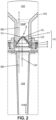
Figure 2 illustrates an operation of a filtering system implemented in the aerosol-generating device ofFigure 1 . -
Figures 3a and3b are an exploded view and a perspective view of a first possible embodiment of the filtering system ofFigure 2 . -
Figures 4a and4b correspond toFigures 3a and3b for a second possible embodiment of the filtering system ofFigure 2 . -
Figures 5a and5b correspond toFigures 3a and3b for a third possible embodiment of the filtering system ofFigure 2 . - For clarity sake, element sizes which appear in these figures do not correspond to actual dimensions or dimension ratios. Also, same reference numbers which are indicated in different ones of these figures denote identical elements of elements with identical function.
- Referring to
Figure 1 , an aerosol-generating device comprises abody 100 which has an elongated shape along a longitudinal direction L and extends between aproximal end 100P and adistal end 100D. When using the device, a user inhales air loaded with aerosol from theproximal end 100P of thebody 100. To this purpose, thebody 100 at itsproximal end 100P may be formed as amouthpiece 103, and the use position of the aerosol-generating device corresponds to theproximal end 100P oriented upwards relative to thedistal end 100D. According to a possible design of the aerosol-generating device, the bottom part of thebody 100 may accommodate abattery 110 andelectrical circuitry 111 suitable for controlling operation of the aerosol-generating device and recharge of the battery. The upper part of thebody 100 is provided with acompartment 101 suitable for accommodating apod 200 which contains an aerosol-generating substrate. Aheater 102 may be located near a lower part of thepod 200, and thepod 200 arranged for delivering liquid from the aerosol-generating substrate to theheater 102. Anairflow path 104 extends from the heater location to anoutlet 105 located at theproximal end 100P of thebody 100. Thus, aproximal end 104P of theairflow path 104 opens up in theoutlet 105, and theheater 102 is located at adistal end 104D of theairflow path 104. In such arrangement, theairflow path 104 may extend through thepod 200, but alternative arrangements of the aerosol-generating device are also possible. When the user draws air by inhaling at theoutlet 105, air flows in theairflow path 104 fromdistal end 104D toproximal end 104P and simultaneously theheater 102 vaporizes the liquid. The vapour is thus conveyed by the air which cools down when moving to theproximal end 104P, so that the vapour condensates to form aerosol droplets. These droplets are usually of less than 300 µm in diameter, and suitable for providing nice vaping experience to the user. - However, it happens during this operation that too much liquid is delivered by the
pod 200 at one time to theheater 102. Then, additionally to vaporizing part of this liquid as just described, theheater 102 ejects some of the in-excess liquid into droplets of more than 500 µm. This undesired behaviour is called spitting. When such large droplets enter the mouth of the user after having travelled along theairflow path 104, they cause unpleasant feeling to the user. The present invention provides afiltering system 10 mounted in theairflow path 104, preferably at itsproximal end 104P, for retaining the large droplets of more that 500 µm in diameter and avoiding that these large droplets enter the user's mouth. Preferably, thefiltering system 10 is selected for blocking droplets above the limit of 300 µm for the droplet diameter. Blocked droplets then form collected liquid at thefiltering system 10, and an improvement of the invention prevents this collected liquid from flowing back to theheater 102 and then causing further spitting. - This invention improvement provides that a filtering porous partition of the
filtering system 10 has a shape that allows removal of the liquid collected by this filtering porous partition, from a center part thereof. This shape is cone-like or pyramid-like or may also be dome-like. Such shape in combination with gravity makes the liquid which is collected by the filtering porous partition flow along this latter to a defined location where it can be stored. When so-shaped filtering porous partition has a central apex A which is oriented upwards in the use position of the aerosol-generating device, the collected liquid flows to the peripheral limit of the filtering porous partition. Then, a reservoir may be provided at the peripheral limit of the filtering porous partition, which is in fluid-communication with this latter for absorbing the collected liquid. Preferably, this reservoir may be at least partially filled with a liquid-absorbing portion, so that liquid collected by the filtering porous partition from the retained droplets soaks into the liquid-absorbing portion. In particular, the liquid-absorbing portion may contact the filtering porous partition. In this way, capillarity of the liquid-absorbing portion may participate in an efficiency for retaining the liquid collected in excess by the filtering porous partition. InFigure 2 , the reference numbers listed hereunder denote the following elements: - 1 or 1': the filtering porous partition
- 4: a peripheral frame of the
filtering system 10, in which the reservoir is provided - 2: the liquid-absorbing portion, inserted into the reservoir
- 5: a retaining portion, also called plug, which may be press-fitted into an aperture of the reservoir for sealing it, so as to maintain the liquid-absorbing
portion 2 and the stored liquid inside the reservoir - LD: droplets larger than 500 µm in diameter, possibly produced by the
heater 102 through spitting behaviour, and blocked by the filteringporous partition 1 or 1' - SD: droplets smaller than 300 µm in diameter, passing through the filtering
porous partition 1 or 1' and providing nice vaping experience to the user - CL: liquid collected by the filtering
porous partition 1 or 1' and soaking into the liquid-absorbingportion 2 - The liquid-absorbing
portion 2 may be a foam portion, for example polyurethane-based. Alternatively, it may be a fibrous portion, for example based on cellulose or cotton fibers. - The
frame 4 may be of a plastic or thermoplastic material, such as polycarbonate, and the retainingportion 5 may be rubber-based. Thanks to implementing theframe 4, thefiltering system 10 appears as a one-piece element which can be mounted easily in theairflow path 104 near itsproximal end 104P or in themouthpiece 103. Silicone-based adhesive may be used to secure it at proper location. In this way, thefiltering system 10 can be mounted into a new aerosol-generating device when manufacturing this latter, but also added to an already-existing aerosol-generating device during a retrofit procedure. - The embodiments disclosed now illustrate three possibilities for ensuring that the filtering porous partition remains with its nominal shape during assembling in the aerosol-generating device and over the service time of this latter, even when loaded with liquid from the blocked large droplets.
- In the embodiment of
Figures 3a and3b , the filteringporous partition 1 may be comprised of a synthetic polymer, for example a polyamide-based synthetic polymer such as nylon@, forming a mesh suitable for retaining the droplets of more than 500 µm, preferably of more than 300 µm, in diameter from the aerosol. Then, areinforcement grid 3 is added in thefiltering system 10, and maintained against the filteringporous partition 1 by theperipheral frame 4, above or below the filtering porous partition. Thereinforcement grid 3 may be a metal grid, for example made from stainless steel or titanium wire. Thereinforcement grid 3 may itself have a dome- or cone- or pyramid-like shape so as to impart such form to the filteringporous partition 1. It may be press-fitted together with the filteringporous partition 1 into theperipheral frame 4. - In the embodiment of
Figures 4a and4b , the filteringporous partition 1 may be comprised again of nylon@ mesh suitable for retaining the droplets of more than 500 µm, or more than 300 µm, but it incorporates reinforcement elements 3' which are embedded in the nylon® mesh. These reinforcement elements 3' may only have the function of ensuring that the shape of the filteringporous partition 1 remains over time, but they do not participate in the filtering function that is effective for the droplets. The reinforcement elements 3' may be plastic of metal fibers which are dispersed within the nylon@ mesh. - In the embodiment of
Figures 5a and5b , the filtering porous partition 1' may be comprised of a metal mesh, preferably a stainless steel or titanium mesh, that is suitable to produce the function of filtering the droplets based on their individual diameter values. Such metal mesh is rigid enough to remain in shape over the lifetime of the aerosol-generating device.
Claims (15)
- An aerosol-generating device suitable for delivering an aerosol from an aerosol-generating substrate, the aerosol-generating device comprising:- a body (100) extending in a longitudinal direction (L) between a proximal end (100P) and a distal end (100D), the body comprising a pod compartment (101) for accommodating a pod (200) containing the aerosol-generating substrate;- an outlet (105) located at the proximal end (100P) of the body (100);- an airflow path (104) for delivering the aerosol from the aerosol-generating substrate to the outlet (105); and- a filtering system (10) arranged in the airflow path (104) and configured to retain droplets of more than 500 µm, preferably of more than 300 µm, in diameter from the aerosol,wherein the filtering system (10) comprises a filtering porous partition (1; 1') that is shaped as a dome or a cone or a pyramid.
- The aerosol-generating device of claim 1, wherein the body (100) further comprises:- a heater (102) arranged for heating the aerosol-generating substrate when the pod (200) is in the pod compartment (101), so as to produce the aerosol.
- The aerosol-generating device of claim 2, wherein the heater (102) is located at a distal end of the pod compartment (101) oriented towards the distal end (100D) of the body (100), and the airflow path (104) extends between the heater at a distal end (104D) of said airflow path and the outlet (105) at a proximal end (104P) of said airflow path, when the pod (200) is accommodated in the pod compartment,
and wherein the filtering system (10) is located at a region nearer to the proximal end (104P) of the airflow path (104), compared to the distal end (104D) of said airflow path. - The aerosol-generating device of one of the preceding claims, wherein the filtering porous partition (1; 1') is shaped to have a center apex (A) that is offset toward the proximal end (104P) of the airflow path (104) compared to a peripheral limit of said filtering porous partition.
- The aerosol-generating device of one of the preceding claims, wherein the filtering system (10) further comprises a liquid-absorbing portion (2) that contacts the filtering porous partition (1; 1'), so that liquid that is collected by the filtering porous partition from the retained droplets soaks into the liquid-absorbing portion.
- The aerosol-generating device of claims 4 and 5, wherein the liquid-absorbing portion (2) contacts the filtering porous partition (1; 1') at the peripheral limit of said filtering porous partition.
- The aerosol-generating device of claim 5 or 6, wherein the liquid-absorbing portion (2) is based on polyurethane or cellulose or cotton.
- The aerosol-generating device of one of claims 5 to 7, wherein the filtering system (10) further comprises a frame (4) designed for maintaining the filtering porous partition (1; 1') and the liquid-absorbing portion (2) so as to form altogether a one-piece element.
- The aerosol-generating device of claim 8, wherein the filtering system (10) further comprises a retaining portion (5) that maintains the liquid-absorbing portion (2) in the frame (4).
- The aerosol-generating device of one of claims 1 to 9, wherein the filtering porous partition (1) is comprised of a synthetic polymer, preferably a polyamide-based synthetic polymer, in a form suitable for retaining the droplets of more than 500 µm, preferably of more than 300 µm, in diameter from the aerosol,and wherein the filtering system (10) further comprises a reinforcement grid (3) that is arranged close to the filtering porous partition (1) to maintain a shape of said filtering porous partition,the frame (4) further securing the reinforcement grid (3) close to the filtering porous partition (1).
- The aerosol-generating device of claim 10, wherein the reinforcement grid (3) is shaped as a dome or a cone or a pyramid.
- The aerosol-generating device of one of claims 1 to 9, wherein the filtering porous partition (1) is comprised of synthetic polymer, preferably a polyamide-based synthetic polymer, in a form suitable for retaining the droplets of more than 500 µm, preferably of more than 300 µm, in diameter from the aerosol,
and the filtering porous partition (1) incorporates embedded reinforcement elements (3') suitable for maintaining a shape of the filtering porous partition (1). - The aerosol-generating device of one of claims 1 to 9, wherein the filtering porous partition (1') is comprised of a metal mesh, preferably a stainless steel or titanium mesh, said metal mesh being suitable for retaining the droplets of more than 500 µm, preferably of more than 300 µm, in diameter from the aerosol.
- The aerosol-generating device of one of the preceding claims, wherein the filtering system (10) is secured across the airflow path (104) by means of an adhesive, in particular a silicone-based adhesive.
- The aerosol-generating device of one of the preceding claims, wherein the body (100) comprises a mouthpiece (103), and the filtering system (10) is located within the mouthpiece.
Priority Applications (2)
| Application Number | Priority Date | Filing Date | Title |
|---|---|---|---|
| EP23186518.9A EP4494495A1 (en) | 2023-07-19 | 2023-07-19 | Aerosol-generating device with filtering system |
| US18/763,428 US20250024884A1 (en) | 2023-07-19 | 2024-07-03 | Aerosol-Generating Device with Filtering System |
Applications Claiming Priority (1)
| Application Number | Priority Date | Filing Date | Title |
|---|---|---|---|
| EP23186518.9A EP4494495A1 (en) | 2023-07-19 | 2023-07-19 | Aerosol-generating device with filtering system |
Publications (1)
| Publication Number | Publication Date |
|---|---|
| EP4494495A1 true EP4494495A1 (en) | 2025-01-22 |
Family
ID=87426815
Family Applications (1)
| Application Number | Title | Priority Date | Filing Date |
|---|---|---|---|
| EP23186518.9A Withdrawn EP4494495A1 (en) | 2023-07-19 | 2023-07-19 | Aerosol-generating device with filtering system |
Country Status (2)
| Country | Link |
|---|---|
| US (1) | US20250024884A1 (en) |
| EP (1) | EP4494495A1 (en) |
Citations (3)
| Publication number | Priority date | Publication date | Assignee | Title |
|---|---|---|---|---|
| US20220015433A1 (en) | 2018-12-07 | 2022-01-20 | Philip Morris Products S.A. | Aerosol generating system and cartridge with leakage protection |
| CN218043795U (en) * | 2022-08-31 | 2022-12-16 | 深圳市卓尔悦电子科技有限公司 | Nebulizer and aerosol generating device |
| CN218245630U (en) * | 2022-05-31 | 2023-01-10 | 深圳市致远智创科技有限公司 | Electronic cigarette atomizer capable of preventing mistaken smoking of tobacco tar |
-
2023
- 2023-07-19 EP EP23186518.9A patent/EP4494495A1/en not_active Withdrawn
-
2024
- 2024-07-03 US US18/763,428 patent/US20250024884A1/en active Pending
Patent Citations (3)
| Publication number | Priority date | Publication date | Assignee | Title |
|---|---|---|---|---|
| US20220015433A1 (en) | 2018-12-07 | 2022-01-20 | Philip Morris Products S.A. | Aerosol generating system and cartridge with leakage protection |
| CN218245630U (en) * | 2022-05-31 | 2023-01-10 | 深圳市致远智创科技有限公司 | Electronic cigarette atomizer capable of preventing mistaken smoking of tobacco tar |
| CN218043795U (en) * | 2022-08-31 | 2022-12-16 | 深圳市卓尔悦电子科技有限公司 | Nebulizer and aerosol generating device |
Also Published As
| Publication number | Publication date |
|---|---|
| US20250024884A1 (en) | 2025-01-23 |
Similar Documents
| Publication | Publication Date | Title |
|---|---|---|
| US12090269B2 (en) | Aerosol-generating system having a heater assembly and a cartridge for an aerosol-generating system having a fluid permeable heater assembly | |
| JP7752475B2 (en) | Leak-reduced aerosol generator | |
| KR102659808B1 (en) | Aerosol generation system with enhanced airflow management | |
| EP3585190B1 (en) | Moulded mounting for an aerosol-generating element in an aerosol-generating system | |
| RU2707450C2 (en) | Aerosol-generating system with improved air flow control | |
| EP3585189B1 (en) | An aerosol-generating system and a cartridge for an aerosol generating system having a two-part liquid storage compartment | |
| RU2747612C2 (en) | Aerosol-generating system containing multiple aerosol-forming substrates | |
| EP3104723B1 (en) | Cartridge for an aerosol-generating system | |
| KR102629493B1 (en) | Mouthpiece for aerosol-generating device with woven fiber liner | |
| US20250024884A1 (en) | Aerosol-Generating Device with Filtering System | |
| EP4364176B1 (en) | Aerosol-generating device with automatic disconnection | |
| US20240225107A1 (en) | Aerosol-generating device with overheating prevention | |
| RU2775496C2 (en) | Aerosol-generating apparatus with reduced leaking | |
| HK40062754A (en) | Cartridge for an aerosol-generating system | |
| HK40016012A (en) | Moulded mounting for an aerosol-generating element in an aerosol-generating system | |
| HK1228213A1 (en) | Cartridge for an aerosol-generating system | |
| HK1228213B (en) | Cartridge for an aerosol-generating system |
Legal Events
| Date | Code | Title | Description |
|---|---|---|---|
| PUAI | Public reference made under article 153(3) epc to a published international application that has entered the european phase |
Free format text: ORIGINAL CODE: 0009012 |
|
| STAA | Information on the status of an ep patent application or granted ep patent |
Free format text: STATUS: THE APPLICATION HAS BEEN PUBLISHED |
|
| AK | Designated contracting states |
Kind code of ref document: A1 Designated state(s): AL AT BE BG CH CY CZ DE DK EE ES FI FR GB GR HR HU IE IS IT LI LT LU LV MC ME MK MT NL NO PL PT RO RS SE SI SK SM TR |
|
| STAA | Information on the status of an ep patent application or granted ep patent |
Free format text: STATUS: THE APPLICATION IS DEEMED TO BE WITHDRAWN |
|
| 18D | Application deemed to be withdrawn |
Effective date: 20250723 |