EP4492930A1 - Cover component and electronic device unit - Google Patents
Cover component and electronic device unit Download PDFInfo
- Publication number
- EP4492930A1 EP4492930A1 EP23766559.1A EP23766559A EP4492930A1 EP 4492930 A1 EP4492930 A1 EP 4492930A1 EP 23766559 A EP23766559 A EP 23766559A EP 4492930 A1 EP4492930 A1 EP 4492930A1
- Authority
- EP
- European Patent Office
- Prior art keywords
- cover component
- electronic device
- device body
- electronic calculator
- scientific electronic
- Prior art date
- Legal status (The legal status is an assumption and is not a legal conclusion. Google has not performed a legal analysis and makes no representation as to the accuracy of the status listed.)
- Pending
Links
Images


Classifications
-
- H—ELECTRICITY
- H05—ELECTRIC TECHNIQUES NOT OTHERWISE PROVIDED FOR
- H05K—PRINTED CIRCUITS; CASINGS OR CONSTRUCTIONAL DETAILS OF ELECTRIC APPARATUS; MANUFACTURE OF ASSEMBLAGES OF ELECTRICAL COMPONENTS
- H05K5/00—Casings, cabinets or drawers for electric apparatus
- H05K5/02—Details
- H05K5/03—Covers
-
- G—PHYSICS
- G06—COMPUTING OR CALCULATING; COUNTING
- G06F—ELECTRIC DIGITAL DATA PROCESSING
- G06F1/00—Details not covered by groups G06F3/00 - G06F13/00 and G06F21/00
- G06F1/16—Constructional details or arrangements
- G06F1/1613—Constructional details or arrangements for portable computers
- G06F1/1626—Constructional details or arrangements for portable computers with a single-body enclosure integrating a flat display, e.g. Personal Digital Assistants [PDAs]
-
- G—PHYSICS
- G06—COMPUTING OR CALCULATING; COUNTING
- G06F—ELECTRIC DIGITAL DATA PROCESSING
- G06F1/00—Details not covered by groups G06F3/00 - G06F13/00 and G06F21/00
- G06F1/16—Constructional details or arrangements
- G06F1/1613—Constructional details or arrangements for portable computers
- G06F1/1629—Protective covers or auxiliary enclosures for portable computers
-
- H—ELECTRICITY
- H05—ELECTRIC TECHNIQUES NOT OTHERWISE PROVIDED FOR
- H05K—PRINTED CIRCUITS; CASINGS OR CONSTRUCTIONAL DETAILS OF ELECTRIC APPARATUS; MANUFACTURE OF ASSEMBLAGES OF ELECTRICAL COMPONENTS
- H05K5/00—Casings, cabinets or drawers for electric apparatus
- H05K5/02—Details
- H05K5/0217—Mechanical details of casings
-
- H—ELECTRICITY
- H05—ELECTRIC TECHNIQUES NOT OTHERWISE PROVIDED FOR
- H05K—PRINTED CIRCUITS; CASINGS OR CONSTRUCTIONAL DETAILS OF ELECTRIC APPARATUS; MANUFACTURE OF ASSEMBLAGES OF ELECTRICAL COMPONENTS
- H05K5/00—Casings, cabinets or drawers for electric apparatus
- H05K5/02—Details
- H05K5/0217—Mechanical details of casings
- H05K5/0221—Locks; Latches
-
- Y—GENERAL TAGGING OF NEW TECHNOLOGICAL DEVELOPMENTS; GENERAL TAGGING OF CROSS-SECTIONAL TECHNOLOGIES SPANNING OVER SEVERAL SECTIONS OF THE IPC; TECHNICAL SUBJECTS COVERED BY FORMER USPC CROSS-REFERENCE ART COLLECTIONS [XRACs] AND DIGESTS
- Y02—TECHNOLOGIES OR APPLICATIONS FOR MITIGATION OR ADAPTATION AGAINST CLIMATE CHANGE
- Y02E—REDUCTION OF GREENHOUSE GAS [GHG] EMISSIONS, RELATED TO ENERGY GENERATION, TRANSMISSION OR DISTRIBUTION
- Y02E60/00—Enabling technologies; Technologies with a potential or indirect contribution to GHG emissions mitigation
- Y02E60/10—Energy storage using batteries
Definitions
- the present invention relates to a cover component and an electronic device unit.
- This type of cover component may be configured to be attachable to and detachable from an electronic device body by being provided with a hook part(s) that is engageable with and disengageable from a recess(es) of the electronic device body by elastically deforming.
- Patent Literature 1 JP 2007-190091 A
- the hook part may be worn away by repetition of attachment and detachment of the cover component to and from the electronic device body.
- the hook part When the hook part is worn away, clearance between the hook part and the electronic device body (e.g., the bottom of the recess) may widen, and wobble of the cover component and the electronic device body may become large.
- the present invention has been conceived in view of the above circumstances, and an object thereof is configuring an electronic device body and its cover component to be suitably attachable to and detachable from one another.
- the present invention is a cover component attachable to and detachable from an electronic device body, including:
- an electronic device body and its cover component can be configured to be suitably attachable to and detachable from one another.
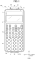
- FIG. 1 is a front view of a scientific electronic calculator 10 with a cover component 20 attached (scientific electronic calculator unit 100) according to this embodiment
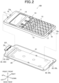
- FIG. 2 is a perspective view of the scientific electronic calculator 10 and the cover component 20.
- the front, back, left, right, up and down directions refer to orientations shown in the drawings. That is, the front-back direction refers to the front-rear direction (thickness direction) of the scientific electronic calculator 10 and the cover component 20, the left-right direction refers to the width direction of the scientific electronic calculator 10 and the cover component 20, and the up-down direction refers to the longitudinal direction of the scientific electronic calculator 10 and the cover component 20 (i.e., direction in which a display screen 12 and a plurality of operation buttons 13, which are described below, line up).
- the cover component 20 is attachable to both the front side and the rear side of the scientific electronic calculator 10.
- parts of the cover component 20 will be described as being present in the front-back direction when the cover component 20 has been attached to the rear side of the scientific electronic calculator 10 as shown in FIG. 1 and FIG. 2 , unless otherwise noted.
- the scientific electronic calculator 10 includes a front case 11 that covers the front face (front face) and a rear case 15 that covers the rear face (back face) and the lateral faces.
- the front case 11 and the rear case 15 engage one another in the front-back direction such that the front case 11 closes up the opening in the front face of the rear case 15, thereby constituting a housing of the scientific electronic calculator 10.
- the upper and lower lateral faces 15a of the rear case 15 are each formed in an arc shape to bulge toward the upper and lower tip sides (toward the outside of the cover component 20), respectively, as their positions get closer to their own centers in the front-back direction (i.e., as their positions get closer to their respective engagement grooves 16 described below). More specifically, each lateral face 15a bulges in the opposite direction to the protruding direction of a hook part 23 (detailed later) corresponding to an engagement groove 16 provided in each lateral face 15a.
- Each of the upper and lower lateral faces 15a is provided with, at substantially the center thereof in the front-back direction, the engagement groove (recess) 16 that catches the below-described hook part 23 of the cover component 20.
- the engagement grooves 16 are each formed to extend along the left-right direction.
- the engagement groove 16 formed in the lower lateral face 15a is divided into two parts of the left and right parts.
- Each of the upper and lower lateral faces 15a is provided with two body ribs 17. These two body ribs 17 are arranged at positions in the left-right direction corresponding to the left and right ends of the engagement groove 16. Each body rib 17 runs from the front end to the back end of the lateral face 15a, and is formed to straddle the engagement groove 16 and extend in the front-back direction (shown in FIG. 4 ). In other words, each lateral face 15a is provided with four body ribs 17 if each of the two body ribs 17 is regarded as being divided into two parts of the front and back parts by the engagement groove 16. The body ribs 17 on each lateral face 15a are arranged at positions in the left-right direction corresponding to ribs 24, which are described below, of the cover component 20.
- Each of the upper and lower lateral faces 15a (including the body ribs 17) is formed to be symmetrical in the front-back direction with respect to the engagement groove 16 at substantially the center in the front-back direction. This allows the cover component 20 to be attached to and detached from both the front side and the rear side of the scientific electronic calculator 10 in the same manner.
- the cover component 20 covers and protects the main face (front face or back face) of the scientific electronic calculator 10, and is configured to be attachable to and detachable from the scientific electronic calculator 10.
- the cover component 20 is made of, for example, translucent ABS (Acrylonitrile Butadiene Styrene) resin.
- the cover component 20 is made of a softer (more deformable) material than the rear case 15 of the scientific electronic calculator 10.
- the cover component 20 has a cover body 21 that covers the main face of the scientific electronic calculator 10.
- the cover body 21 is formed in a shape corresponding to the shape of the scientific electronic calculator 10 in front view, namely, a rectangular plate shape long in the up-down direction that corresponds to the longitudinal direction of the scientific electronic calculator 10.
- the upper and lower ends of the cover body 21 are provided with extensions 22 (upper extension 22U, lower extension 22L) that are curved and extend frontward.
- the upper extension 22U has a protruding flat plate part 221 at the front end.
- the flat plate part 221 is provided to protrude from the front end of the extension 22U upward, and is formed in a substantially flat plate shape perpendicular to the front-back direction.
- This flat plate part 221 is a part to cancel engagement of (to disengage) the hook part 23, which is described below, when the cover component 20 is removed from the scientific electronic calculator 10 by, for example, its user pressing the front face of the part with his/her thumb, thereby elastically deforming the extension 22U upward.
- components of the upper extension 22U and components of the lower extension 22L may be provided with reference signs with “U” and "L” added at the ends, respectively, to be distinguished from one another.
- FIG. 3A is a perspective view of the upper extension 22U.
- FIG. 3B is a perspective view of the lower extension 22L.
- each extension 22 is provided with the hook part 23 that stands in the up-down direction (first direction) toward the center of the cover component 20.
- the upper extension 22U is provided with the hook part 23 on the lower face of the flat plate part 221.
- the hook parts 23 are parts that engage the engagement grooves 16 formed in the upper and lower lateral faces 15a of the rear case 15 of the scientific electronic calculator 10 and are formed to extend in the left-right direction to correspond to the engagement grooves 16.
- the lower hook part 23L is divided into two parts of the left and right parts to correspond to the lower engagement groove 16 of the scientific electronic calculator 10.
- the upper hook part 23U protrudes from the surface of the cover component 20 (surface of the extension 22U) downward
- the lower hook part 23L protrudes from the surface of the cover component 20 (surface of the extension 22L) upward.
- the engagement groove 16 formed in the upper lateral face 15a may not be divided into two parts of the left and right parts.
- the hook part 23L may not be divided into two parts of the left and right parts either.
- the hook parts 23 are formed to be engageable with the engagement grooves 16 of the scientific electronic calculator 10 from both the front side and the rear side. That is, the cover component 20 is attachable to each of the front side and the rear side of the scientific electronic calculator 10 by being reversed in the front-back direction.
- each hook part 23 two ribs 24 are provided adjacent to the hook part 23.
- These ribs 24 are examples of protrusions of the present invention and, as described below, for regulating the position of (positioning) the scientific electronic calculator 10 in the up-down direction in the attached state in which the cover component 20 is attached to the scientific electronic calculator 10 (which is hereinafter simply referred to as "attached state").
- the ribs 24 protrude from the surface of the cover component 20 (surfaces of the extensions 22) in the up-down direction. More specifically, the upper ribs 24U protrude downward, and the lower ribs 24L protrude upward.
- the ribs 24 are arranged to be invisible from the front side (front side) by being covered with the hook parts 23 while supporting the back side of the hook parts 23.
- the ribs 24 are arranged apart from one another in the left-right direction. More specifically, the ribs 24 are arranged at positions in the left-right direction corresponding to the body ribs 17 formed on each of the upper and lower lateral faces 15a of the scientific electronic calculator 10 (shown in FIG. 1 ).
- the scientific electronic calculator 10 is pressed into the cover component 20 in the front-back direction in the state in which the scientific electronic calculator 10 and the cover component 20 are stacked in the front-back direction while the front-side parts of the hook parts 23 of the cover component 20 are abutting the rear-side parts of the lateral faces 15a of the scientific electrotonic calculator 10. Then, as shown in FIG. 4 , after each extension 22 of the cover component 20 elastically deforms outward in the up-down direction, the hook part 23 of the extension 22 engages the engagement groove 16 of the scientific electronic calculator 10, so that the cover component 20 is attached to the scientific electronic calculator 10.
- each rib 24 in the up-down direction closer to the scientific electronic calculator 10 faces the scientific electronic calculator 10, thereby regulating the position of the scientific electronic calculator 10.
- the state in which each rib 24 "faces" the scientific electronic calculator 10 (body rib 17) includes both the state in which they are in contact with (abut) one another and the state in which they have a gap in between.
- the ribs 24 of the cover component 20 abut the body ribs 17 of the scientific electronic calculator 10 in the state in which the extensions 22 of the cover component 20 have elastically deformed to spread outward in the up-down direction (e.g., each spread 0.1 mm in the up-down direction).
- FIG. 4 shows, with a dash-dot-dot line, the state in which the extension 22 of the cover component 20 has not elastically deformed, and the rib 24 of the cover component 20 and the body rib 17 of the scientific electronic calculator 10 get into one another (state that does not actually occur).
- the two extensions 22, namely, the upper and lower extensions 22, of the cover component 20 hold the scientific electronic calculator 10 in between by their elastic force. This makes it possible to properly hold the scientific electronic calculator 10 with no wobble, without, for example, providing the cover body 21 with rubber feet or the like to support the scientific electronic calculator 10.
- the cover component 20 In order to remove (detach) the cover component 20 from the scientific electronic calculator 10, for example, the user presses the front face of the flat plate part 221 of the upper extension 22U with his/her thumb, which elastically deforms the extension 22U upward to extract the hook part 23U from the engagement groove 16 of the scientific electronic calculator 10.
- the cover component 20 can be removed from the scientific electronic calculator 10.
- the back-side walls of the engagement grooves 16 of the scientific electronic calculator 10 press the back faces of the hook parts 23 of the cover component 20, which spreads the extensions 22 outward in the up-down direction and can disengage the hook parts 23 from the engagement grooves 16.
- the hook parts 23 of the cover component 20 may rub against the scientific electronic calculator 10, but the ribs 24 are unlikely to rub against the scientific electronic calculator 10.
- the hook parts 23 may rub against the scientific electronic calculator 10, but the ribs 24 may not rub against the scientific electronic calculator 10.
- the cover component 20 and the scientific electronic calculator 10 are positioned (regulated in position) in the up-down direction by the ribs 24 of the cover component 20 being in contact with the upper and lower lateral faces 15a (body ribs 17) of the scientific electronic calculator 10. That is, the cover component 20 is positioned with the scientific electronic calculator 10 by the ribs 24, which are different from the hook parts 23 that may be worn away when the cover component 20 is attached to or detached from the scientific electronic calculator 10. Therefore, even if the attachment and the detachment are repeated, the wobble of the cover component 20 and the scientific electronic calculator 10 does not become large, and these can keep being positioned properly.
- a hook part(s) that engages a recess(es) of a scientific electronic calculator positions the scientific electronic calculator in the up-down direction (standing direction of the hook part), and repetition of the attachment and the detachment wears away the tip face of the hook part and makes the wobble of the cover component and the scientific electronic calculator large. That is, clearance between the cover component and the scientific electronic calculator may widen from the distance D1 between the tip of the hook part, which is originally used for positioning, and the bottom of the recess to the distance D2 between the extension and the lateral face of the body case.
- the ribs 24, which are different from the hook parts 23 that function as engagement parts with the scientific electronic calculator 10, are in charge of positioning the cover component 20 and the scientific electronic calculator 10, and therefore even if the hook parts 23 are worn away, the ribs 24 can keep positioning the scientific electronic calculator 10 properly.
- the ribs 24 of the cover component 20 and the body ribs 17 of the scientific electronic calculator 10 may not be in contact with (abut) one another but have a gap(s) in between. More specifically, as shown in FIG. 4 , in the attached state of the cover component 20, the distance between the rib 24 and the scientific electronic calculator 10 (body rib 17 in this embodiment) in the up-down direction is shorter than the distance C between the tip of the hook part 23 and the scientific electronic calculator 10 (bottom of the engagement groove 16) in the up-down direction. That is, not the hook parts 23 but the ribs 24 are in the state of being in charge of positioning the cover component 20 and the scientific electronic calculator 10.
- the cover component 20 and the scientific electronic calculator 10 have a gap in between. That is, it is preferable that no ribs 24 be present at the front side of the hook parts 23 because if the ribs 24 are present at the front side of the hook parts 23, the ribs 24 and the hook parts 23 are likely to rub at the time of the attachment of the cover component 20. This makes it possible to smoothly attach and detach the cover component 20 to and from the scientific electronic calculator 10.
- the positions, quantity and so forth of the ribs 24 are not particularly limited.
- only one rib 24 may be provided in the left-right direction. However, it is better to provide a plurality of ribs 24 apart from one another in the left-right direction to stably hold the scientific electronic calculator 10 in the width direction.
- the two extensions 22, namely, the upper and lower extensions 22, are provided with the ribs 24, only one of them may be provided with the ribs 24. In this case, it is preferable that the upper extension 22U having the flat plate part 221 be provided with the ribs 24.
- the ribs 24 position (regulate the position of) the scientific electronic calculator 10 in its longitudinal direction (up-down direction), the ribs 24 need only regulate the position of the scientific electronic calculator 10 in the standing direction of the hook parts 23.
- the ribs 24 may position the scientific electronic calculator 10 in its width direction (left-right direction).
- the relative positions of the ribs 24 and the hook parts 23 are not particularly limited either.
- the ribs 24 may be arranged at the front side of the hook parts 23. However, if the ribs 24 are adjacent to the back side of the hook parts 23 as in this embodiment, the hook parts 23 and the extensions 22 are unlikely to elastically deform since the ribs 24 support the hook parts 23. This can suppress unintentional separation of the cover component 20 from the scientific electronic calculator 10. Further, in light of both attachment stability and attachability/detachability, it is preferable that the ribs 24 be provided only partly in the width direction of the hook parts 23 (right-left direction). Still further, arranging the ribs 24 at the back side of the hook parts 23 makes it possible to smoothly attach and detach the cover component 20 to and from the scientific electronic calculator 10.
- the body ribs 17 are provided on the rear case 15 of the scientific electronic calculator 10 to correspond to the ribs 24 of the cover component 20, the body ribs 17 may not be provided. However, as compared with a case where the lateral faces 15a of the rear case 15 themselves rub against the ribs 24 and are worn away, it is preferable to provide the body ribs 17 especially in terms of aesthetics because worn-away points of the scientific electronic calculator 10 at the time of the attachment/detachment can be the body ribs 17 only.
- the cover component 20 attachable to and detachable from the scientific electronic calculator 10 includes the rib(s) 24 that regulates the position of the scientific electronic calculator 10 in the standing direction of the hook part(s) 23 (up-down direction) in the attached state.
- the ribs 24, which are different from the hook parts 23 that function as the engagement parts with the scientific electronic calculator 10, are in charge of positioning the cover component 20 and the scientific electronic calculator 10. Therefore, even if the hook parts 23 are worn way, the ribs 24 can keep positioning the scientific electronic calculator 10 properly.
- the scientific electronic calculator 10 and its cover component 20 can be configured to be suitably attachable to and detachable from one another.
- one face of the rib 24 faces the scientific electronic calculator 10 and regulates the position thereof.
- each rib 24 since only one face of each rib 24 faces (in this embodiment, is in contact with) the lateral face 15a of the scientific electronic calculator 10, and, unlike the hook parts 23, the ribs 24 are not covered with the recesses (engagement grooves 16), wear of the ribs 24 at the time of the attachment/detachment can be suppressed.
- the distance between the rib 24 and the scientific electronic calculator 10 (body rib 17 in this embodiment) in the up-down direction is shorter than the distance C between the tip of the hook part 23 and the scientific electronic calculator 10 (bottom of the engagement groove 16) in the up-down direction.
- the rib 24 is provided adjacent to the cover body 21 side (back side) of the hook part 23.
- the ribs 24 are provided apart from one another in the left-right direction perpendicular to the up-down direction and the thickness direction of the cover component 20.
- the cover component 20 is made of a softer (more deformable) material than, of the scientific electronic calculator 10, the rear case 15 that the hook part 23 engages.
- the cover component 20 may not be the attachable/detachable type of being attachable to and detachable from the scientific electronic calculator 10 but a sliding type of being attachable to the front side or the rear side of the scientific electronic calculator 10 by sliding on the main face of the scientific electronic calculator 10.
- the electronic device (body) of the present invention is not limited to the scientific electronic calculator (electronic desk calculator) but widely applicable to electronic devices in general to and from which cover components are attachable and detachable, such as an electronic dictionary and a smartphone.
- the present invention is, for example, for suitably attaching and detaching an electronic device body and its cover component to and from one another, and accordingly applicable to a cover component and an electronic device unit.
Landscapes
- Engineering & Computer Science (AREA)
- Microelectronics & Electronic Packaging (AREA)
- Theoretical Computer Science (AREA)
- Computer Hardware Design (AREA)
- Human Computer Interaction (AREA)
- Physics & Mathematics (AREA)
- General Engineering & Computer Science (AREA)
- General Physics & Mathematics (AREA)
- Casings For Electric Apparatus (AREA)
- Calculators And Similar Devices (AREA)
Abstract
Description
- The present invention relates to a cover component and an electronic device unit.
- There has been known a cover component that protects an electronic device body, such as a scientific electronic calculator (e.g., refer to Patent Literature 1).
- This type of cover component may be configured to be attachable to and detachable from an electronic device body by being provided with a hook part(s) that is engageable with and disengageable from a recess(es) of the electronic device body by elastically deforming.
- Patent Literature 1:
JP 2007-190091 A - However, in the structure in which the hook part engages the recess by being elastically deformed by contacting the electronic device body, the hook part may be worn away by repetition of attachment and detachment of the cover component to and from the electronic device body. When the hook part is worn away, clearance between the hook part and the electronic device body (e.g., the bottom of the recess) may widen, and wobble of the cover component and the electronic device body may become large.
- The present invention has been conceived in view of the above circumstances, and an object thereof is configuring an electronic device body and its cover component to be suitably attachable to and detachable from one another.
- In order to achieve the aforementioned object, the present invention is a cover component attachable to and detachable from an electronic device body, including:
- a hook part that stands in a first direction and engages the electronic device body; and
- a protrusion that regulates a position of the electronic device body in the first direction in an attached state in which the cover component is attached to the electronic device body.
- According to the present invention, an electronic device body and its cover component can be configured to be suitably attachable to and detachable from one another.
-
- [
FIG. 1 ] This is a front view of a scientific electronic calculator unit according to an embodiment. - [
FIG. 2 ] This is a perspective view of a scientific electronic calculator and a cover component according to the embodiment. - [
FIG. 3A ] This is a perspective view of an upper extension. - [
FIG. 3B ] This is a perspective view of a lower extension. - [
FIG. 4 ] This is a vertical sectional view of the upper end part of the scientific electronic calculator with the cover component attached to the rear side. - [
FIG. 5 ] This shows an attached state of a conventional cover component to a scientific electronic calculator. - With reference to
FIG. 1 to FIG. 5 , an embodiment of the present invention will be described. - The embodiment described below is provided with various technically preferred limitations for carrying out the present invention. The technical scope of the present invention is not limited to the embodiment below or illustrated examples.
-
FIG. 1 is a front view of a scientificelectronic calculator 10 with acover component 20 attached (scientific electronic calculator unit 100) according to this embodiment, andFIG. 2 is a perspective view of the scientificelectronic calculator 10 and thecover component 20. - Hereinafter, the front, back, left, right, up and down directions refer to orientations shown in the drawings. That is, the front-back direction refers to the front-rear direction (thickness direction) of the scientific
electronic calculator 10 and thecover component 20, the left-right direction refers to the width direction of the scientificelectronic calculator 10 and thecover component 20, and the up-down direction refers to the longitudinal direction of the scientificelectronic calculator 10 and the cover component 20 (i.e., direction in which adisplay screen 12 and a plurality ofoperation buttons 13, which are described below, line up). - As described below, the
cover component 20 is attachable to both the front side and the rear side of the scientificelectronic calculator 10. Hereinafter, however, parts of thecover component 20 will be described as being present in the front-back direction when thecover component 20 has been attached to the rear side of the scientificelectronic calculator 10 as shown inFIG. 1 andFIG. 2 , unless otherwise noted. - The scientific
electronic calculator 10 is an example of the electronic device body of the present invention, and, as shown inFIG. 1 andFIG. 2 , formed in a rectangular plate shape long in the up-down direction. The scientificelectronic calculator 10 is paired with thecover component 20, thereby constituting the scientific electronic calculator unit (electronic device unit) 100. - More specifically, the scientific
electronic calculator 10 includes afront case 11 that covers the front face (front face) and arear case 15 that covers the rear face (back face) and the lateral faces. Thefront case 11 and therear case 15 engage one another in the front-back direction such that thefront case 11 closes up the opening in the front face of therear case 15, thereby constituting a housing of the scientificelectronic calculator 10. - On the
front case 11, thedisplay screen 12 where various types of information are displayed and theoperation buttons 13 that receive user operations are arranged. - Although not particularly limited, the
rear case 15 is made of high impact polystyrene (HIPS) resin. - The upper and lower
lateral faces 15a of therear case 15 are each formed in an arc shape to bulge toward the upper and lower tip sides (toward the outside of the cover component 20), respectively, as their positions get closer to their own centers in the front-back direction (i.e., as their positions get closer to theirrespective engagement grooves 16 described below). More specifically, eachlateral face 15a bulges in the opposite direction to the protruding direction of a hook part 23 (detailed later) corresponding to anengagement groove 16 provided in eachlateral face 15a. - Each of the upper and lower
lateral faces 15a is provided with, at substantially the center thereof in the front-back direction, the engagement groove (recess) 16 that catches the below-described hook part 23 of thecover component 20. Theengagement grooves 16 are each formed to extend along the left-right direction. Although not particularly limited, theengagement groove 16 formed in the lowerlateral face 15a is divided into two parts of the left and right parts. - Each of the upper and lower
lateral faces 15a is provided with twobody ribs 17. These twobody ribs 17 are arranged at positions in the left-right direction corresponding to the left and right ends of theengagement groove 16. Each body rib 17 runs from the front end to the back end of thelateral face 15a, and is formed to straddle theengagement groove 16 and extend in the front-back direction (shown inFIG. 4 ). In other words, eachlateral face 15a is provided with fourbody ribs 17 if each of the twobody ribs 17 is regarded as being divided into two parts of the front and back parts by theengagement groove 16. Thebody ribs 17 on eachlateral face 15a are arranged at positions in the left-right direction corresponding toribs 24, which are described below, of thecover component 20. - Each of the upper and lower
lateral faces 15a (including the body ribs 17) is formed to be symmetrical in the front-back direction with respect to theengagement groove 16 at substantially the center in the front-back direction. This allows thecover component 20 to be attached to and detached from both the front side and the rear side of the scientificelectronic calculator 10 in the same manner. - The
cover component 20 covers and protects the main face (front face or back face) of the scientificelectronic calculator 10, and is configured to be attachable to and detachable from the scientificelectronic calculator 10. Thecover component 20 is made of, for example, translucent ABS (Acrylonitrile Butadiene Styrene) resin. Thecover component 20 is made of a softer (more deformable) material than therear case 15 of the scientificelectronic calculator 10. Thecover component 20 has acover body 21 that covers the main face of the scientificelectronic calculator 10. - The
cover body 21 is formed in a shape corresponding to the shape of the scientificelectronic calculator 10 in front view, namely, a rectangular plate shape long in the up-down direction that corresponds to the longitudinal direction of the scientificelectronic calculator 10. - The upper and lower ends of the
cover body 21 are provided with extensions 22 (upper extension 22U, lower extension 22L) that are curved and extend frontward. The upper extension 22U has a protrudingflat plate part 221 at the front end. Theflat plate part 221 is provided to protrude from the front end of the extension 22U upward, and is formed in a substantially flat plate shape perpendicular to the front-back direction. Thisflat plate part 221 is a part to cancel engagement of (to disengage) the hook part 23, which is described below, when thecover component 20 is removed from the scientificelectronic calculator 10 by, for example, its user pressing the front face of the part with his/her thumb, thereby elastically deforming the extension 22U upward. - Hereinafter, components of the upper extension 22U and components of the lower extension 22L may be provided with reference signs with "U" and "L" added at the ends, respectively, to be distinguished from one another.
-
FIG. 3A is a perspective view of the upper extension 22U.FIG. 3B is a perspective view of the lower extension 22L. - As shown in these drawings, the tip (front end) of each
extension 22 is provided with the hook part 23 that stands in the up-down direction (first direction) toward the center of thecover component 20. More precisely, the upper extension 22U is provided with the hook part 23 on the lower face of theflat plate part 221. The hook parts 23 are parts that engage theengagement grooves 16 formed in the upper and lower lateral faces 15a of therear case 15 of the scientificelectronic calculator 10 and are formed to extend in the left-right direction to correspond to theengagement grooves 16. The lower hook part 23L is divided into two parts of the left and right parts to correspond to thelower engagement groove 16 of the scientificelectronic calculator 10. More specifically, the upper hook part 23U protrudes from the surface of the cover component 20 (surface of the extension 22U) downward, and the lower hook part 23L protrudes from the surface of the cover component 20 (surface of the extension 22L) upward. Like theengagement groove 16 formed in the upperlateral face 15a, theengagement groove 16 formed in the lowerlateral face 15a may not be divided into two parts of the left and right parts. In this case, the hook part 23L may not be divided into two parts of the left and right parts either. The hook parts 23 are formed to be engageable with theengagement grooves 16 of the scientificelectronic calculator 10 from both the front side and the rear side. That is, thecover component 20 is attachable to each of the front side and the rear side of the scientificelectronic calculator 10 by being reversed in the front-back direction. - At the back side (cover
body 21 side where thecover body 21 is provided) of each hook part 23, tworibs 24 are provided adjacent to the hook part 23. Theseribs 24 are examples of protrusions of the present invention and, as described below, for regulating the position of (positioning) the scientificelectronic calculator 10 in the up-down direction in the attached state in which thecover component 20 is attached to the scientific electronic calculator 10 (which is hereinafter simply referred to as "attached state"). Theribs 24 protrude from the surface of the cover component 20 (surfaces of the extensions 22) in the up-down direction. More specifically, the upper ribs 24U protrude downward, and the lower ribs 24L protrude upward. Theribs 24 are arranged to be invisible from the front side (front side) by being covered with the hook parts 23 while supporting the back side of the hook parts 23. Theribs 24 are arranged apart from one another in the left-right direction. More specifically, theribs 24 are arranged at positions in the left-right direction corresponding to thebody ribs 17 formed on each of the upper and lower lateral faces 15a of the scientific electronic calculator 10 (shown inFIG. 1 ). -
FIG. 4 is a vertical sectional view of the upper end part of the scientificelectronic calculator 10 with thecover component 20 attached to the rear side. - In order to attach the
cover component 20 to the rear side of the scientificelectronic calculator 10, the scientificelectronic calculator 10 is pressed into thecover component 20 in the front-back direction in the state in which the scientificelectronic calculator 10 and thecover component 20 are stacked in the front-back direction while the front-side parts of the hook parts 23 of thecover component 20 are abutting the rear-side parts of the lateral faces 15a of the scientificelectrotonic calculator 10. Then, as shown inFIG. 4 , after eachextension 22 of thecover component 20 elastically deforms outward in the up-down direction, the hook part 23 of theextension 22 engages theengagement groove 16 of the scientificelectronic calculator 10, so that thecover component 20 is attached to the scientificelectronic calculator 10. - In this attached state, one face of each
rib 24 in the up-down direction closer to the scientific electronic calculator 10 (right face of therib 24 inFIG. 4 ) faces the scientificelectronic calculator 10, thereby regulating the position of the scientificelectronic calculator 10. The state in which eachrib 24 "faces" the scientific electronic calculator 10 (body rib 17) includes both the state in which they are in contact with (abut) one another and the state in which they have a gap in between. - In this embodiment, the
ribs 24 of thecover component 20 abut thebody ribs 17 of the scientificelectronic calculator 10 in the state in which theextensions 22 of thecover component 20 have elastically deformed to spread outward in the up-down direction (e.g., each spread 0.1 mm in the up-down direction).FIG. 4 shows, with a dash-dot-dot line, the state in which theextension 22 of thecover component 20 has not elastically deformed, and therib 24 of thecover component 20 and thebody rib 17 of the scientificelectronic calculator 10 get into one another (state that does not actually occur). The twoextensions 22, namely, the upper andlower extensions 22, of thecover component 20 hold the scientificelectronic calculator 10 in between by their elastic force. This makes it possible to properly hold the scientificelectronic calculator 10 with no wobble, without, for example, providing thecover body 21 with rubber feet or the like to support the scientificelectronic calculator 10. - In order to remove (detach) the
cover component 20 from the scientificelectronic calculator 10, for example, the user presses the front face of theflat plate part 221 of the upper extension 22U with his/her thumb, which elastically deforms the extension 22U upward to extract the hook part 23U from theengagement groove 16 of the scientificelectronic calculator 10. Thus, thecover component 20 can be removed from the scientificelectronic calculator 10. Alternatively, by separating thecover component 20 and the scientificelectronic calculator 10 from one another in the front-down direction, the back-side walls of theengagement grooves 16 of the scientificelectronic calculator 10 press the back faces of the hook parts 23 of thecover component 20, which spreads theextensions 22 outward in the up-down direction and can disengage the hook parts 23 from theengagement grooves 16. - Thus, when the
cover component 20 is attached to or detached from the scientificelectronic calculator 10, the hook parts 23 of thecover component 20 may rub against the scientificelectronic calculator 10, but theribs 24 are unlikely to rub against the scientificelectronic calculator 10. At the time of the attachment/detachment, for example, when thecover component 20 is removed from the scientificelectronic calculator 10 by theextensions 22 being spread outward in the up-down direction, depending on the attaching/detaching method, the hook parts 23 may rub against the scientificelectronic calculator 10, but theribs 24 may not rub against the scientificelectronic calculator 10. In the attached state of thecover component 20, thecover component 20 and the scientificelectronic calculator 10 are positioned (regulated in position) in the up-down direction by theribs 24 of thecover component 20 being in contact with the upper and lower lateral faces 15a (body ribs 17) of the scientificelectronic calculator 10. That is, thecover component 20 is positioned with the scientificelectronic calculator 10 by theribs 24, which are different from the hook parts 23 that may be worn away when thecover component 20 is attached to or detached from the scientificelectronic calculator 10. Therefore, even if the attachment and the detachment are repeated, the wobble of thecover component 20 and the scientificelectronic calculator 10 does not become large, and these can keep being positioned properly. - That is, in a conventional cover component having no
ribs 24, as shown inFIG. 5 , a hook part(s) that engages a recess(es) of a scientific electronic calculator (body case) positions the scientific electronic calculator in the up-down direction (standing direction of the hook part), and repetition of the attachment and the detachment wears away the tip face of the hook part and makes the wobble of the cover component and the scientific electronic calculator large. That is, clearance between the cover component and the scientific electronic calculator may widen from the distance D1 between the tip of the hook part, which is originally used for positioning, and the bottom of the recess to the distance D2 between the extension and the lateral face of the body case. - In this regard, in the
cover component 20 of this embodiment, theribs 24, which are different from the hook parts 23 that function as engagement parts with the scientificelectronic calculator 10, are in charge of positioning thecover component 20 and the scientificelectronic calculator 10, and therefore even if the hook parts 23 are worn away, theribs 24 can keep positioning the scientificelectronic calculator 10 properly. - As described above, the
ribs 24 of thecover component 20 and thebody ribs 17 of the scientificelectronic calculator 10 may not be in contact with (abut) one another but have a gap(s) in between. More specifically, as shown inFIG. 4 , in the attached state of thecover component 20, the distance between therib 24 and the scientific electronic calculator 10 (body rib 17 in this embodiment) in the up-down direction is shorter than the distance C between the tip of the hook part 23 and the scientific electronic calculator 10 (bottom of the engagement groove 16) in the up-down direction. That is, not the hook parts 23 but theribs 24 are in the state of being in charge of positioning thecover component 20 and the scientificelectronic calculator 10. - Further, in the attached state of the
cover component 20, at the opposite side (front side) of the hook parts 23 to thecover body 21 side, thecover component 20 and the scientificelectronic calculator 10 have a gap in between. That is, it is preferable that noribs 24 be present at the front side of the hook parts 23 because if theribs 24 are present at the front side of the hook parts 23, theribs 24 and the hook parts 23 are likely to rub at the time of the attachment of thecover component 20. This makes it possible to smoothly attach and detach thecover component 20 to and from the scientificelectronic calculator 10. - The positions, quantity and so forth of the
ribs 24 are not particularly limited. - For example, only one
rib 24 may be provided in the left-right direction. However, it is better to provide a plurality ofribs 24 apart from one another in the left-right direction to stably hold the scientificelectronic calculator 10 in the width direction. - Further, although the two
extensions 22, namely, the upper andlower extensions 22, are provided with theribs 24, only one of them may be provided with theribs 24. In this case, it is preferable that the upper extension 22U having theflat plate part 221 be provided with theribs 24. - Still further, although the
ribs 24 position (regulate the position of) the scientificelectronic calculator 10 in its longitudinal direction (up-down direction), theribs 24 need only regulate the position of the scientificelectronic calculator 10 in the standing direction of the hook parts 23. For example, theribs 24 may position the scientificelectronic calculator 10 in its width direction (left-right direction). - Yet further, the relative positions of the
ribs 24 and the hook parts 23 are not particularly limited either. Theribs 24 may be arranged at the front side of the hook parts 23. However, if theribs 24 are adjacent to the back side of the hook parts 23 as in this embodiment, the hook parts 23 and theextensions 22 are unlikely to elastically deform since theribs 24 support the hook parts 23. This can suppress unintentional separation of thecover component 20 from the scientificelectronic calculator 10. Further, in light of both attachment stability and attachability/detachability, it is preferable that theribs 24 be provided only partly in the width direction of the hook parts 23 (right-left direction). Still further, arranging theribs 24 at the back side of the hook parts 23 makes it possible to smoothly attach and detach thecover component 20 to and from the scientificelectronic calculator 10. - Further, although the
body ribs 17 are provided on therear case 15 of the scientificelectronic calculator 10 to correspond to theribs 24 of thecover component 20, thebody ribs 17 may not be provided. However, as compared with a case where the lateral faces 15a of therear case 15 themselves rub against theribs 24 and are worn away, it is preferable to provide thebody ribs 17 especially in terms of aesthetics because worn-away points of the scientificelectronic calculator 10 at the time of the attachment/detachment can be thebody ribs 17 only. - As described above, according to this embodiment, the
cover component 20 attachable to and detachable from the scientificelectronic calculator 10 includes the rib(s) 24 that regulates the position of the scientificelectronic calculator 10 in the standing direction of the hook part(s) 23 (up-down direction) in the attached state. - Unlike the conventional art, in which a hook part(s) that engages a scientific electronic calculator positions the scientific electronic calculator, the
ribs 24, which are different from the hook parts 23 that function as the engagement parts with the scientificelectronic calculator 10, are in charge of positioning thecover component 20 and the scientificelectronic calculator 10. Therefore, even if the hook parts 23 are worn way, theribs 24 can keep positioning the scientificelectronic calculator 10 properly. Thus, the scientificelectronic calculator 10 and itscover component 20 can be configured to be suitably attachable to and detachable from one another. - Further, according to this embodiment, in the attached state of the
cover component 20, one face of therib 24 faces the scientificelectronic calculator 10 and regulates the position thereof. - That is, since only one face of each
rib 24 faces (in this embodiment, is in contact with) thelateral face 15a of the scientificelectronic calculator 10, and, unlike the hook parts 23, theribs 24 are not covered with the recesses (engagement grooves 16), wear of theribs 24 at the time of the attachment/detachment can be suppressed. - Further, according to this embodiment, in the attached state of the
cover component 20, the distance between therib 24 and the scientific electronic calculator 10 (body rib 17 in this embodiment) in the up-down direction is shorter than the distance C between the tip of the hook part 23 and the scientific electronic calculator 10 (bottom of the engagement groove 16) in the up-down direction. - This allows the scientific
electronic calculator 10 to be positioned in the up-down direction more reliably by not the hook parts 23 but theribs 24. - Further, according to this embodiment, the
rib 24 is provided adjacent to thecover body 21 side (back side) of the hook part 23. - This allows the
ribs 24 to be arranged to be invisible from the front side by being covered with the hook parts 23 and therefore not to impair the aesthetics. - Further, according to this embodiment, the
ribs 24 are provided apart from one another in the left-right direction perpendicular to the up-down direction and the thickness direction of thecover component 20. - This allows the scientific
electronic calculator 10 to be stably held in the left-right direction (width direction) . - Further, according to this embodiment, the
cover component 20 is made of a softer (more deformable) material than, of the scientificelectronic calculator 10, therear case 15 that the hook part 23 engages. - This can suppress deformation and wear of the scientific electronic calculator 10 (rear case 15) due to the attachment/detachment of the
cover component 20 to/from the scientificelectronic calculator 10. - It goes without saying that embodiments to which the present invention is applicable are not limited to the embodiment described above, and various modifications can be made without departing from the scope of the present invention.
- For example, the
cover component 20 may not be the attachable/detachable type of being attachable to and detachable from the scientificelectronic calculator 10 but a sliding type of being attachable to the front side or the rear side of the scientificelectronic calculator 10 by sliding on the main face of the scientificelectronic calculator 10. - Further, the electronic device (body) of the present invention is not limited to the scientific electronic calculator (electronic desk calculator) but widely applicable to electronic devices in general to and from which cover components are attachable and detachable, such as an electronic dictionary and a smartphone.
- Although some embodiments of the present invention have been described above, the scope of the present invention is not limited to the embodiments described above but includes the scope of the invention described in claims and the scope of equivalents thereof.
- The present invention is, for example, for suitably attaching and detaching an electronic device body and its cover component to and from one another, and accordingly applicable to a cover component and an electronic device unit.
-
- 10 Scientific Electronic Calculator (Electronic Device Body)
- 11 Front Case
- 15 Rear Case (Case)
- 15a Lateral Face
- 16 Engagement Groove (Recess)
- 17 Body Rib
- 20 Cover Component
- 21 Cover Body
- 22 Extension
- 23 Hook Part
- 24 Rib (Protrusion)
- 100 Scientific Electronic Calculator Unit (Electronic Device Unit)
- C Distance (Distance between Tip of Hook Part and Scientific Electronic Calculator in Up-Down Direction)
Claims (12)
- A cover component attachable to and detachable from an electronic device body, comprising:a hook part that stands in a first direction and engages the electronic device body; anda protrusion that regulates a position of the electronic device body in the first direction in an attached state in which the cover component is attached to the electronic device body.
- The cover component according to claim 1, wherein the protrusion protrudes from a surface of the cover component to one side in the first direction.
- The cover component according to claim 1 or 2, wherein in the attached state, the protrusion regulates the position of the electronic device body by one face thereof facing the electronic device body.
- The cover component according to any one of claims 1 to 3, wherein in the attached state, a distance between the protrusion and the electronic device body in the first direction is shorter than a distance between a tip of the hook part and the electronic device body in the first direction.
- The cover component according to any one of claims 1 to 4, wherein the first direction is a direction corresponding to a longitudinal direction of the electronic device body.
- The cover component according to any one of claims 1 to 5, comprising a cover body that covers a main face of the electronic device body,
wherein the protrusion is provided adjacent to, of the hook part, a side where the cover body is provided. - The cover component according to any one of claims 1 to 5, comprising a cover body that covers a main face of the electronic device body,
wherein in the attached state, of the hook part, at a side opposite to a side where the cover body is provided, the cover component and the electronic device body have a gap in between. - The cover component according to any one of claims 1 to 7, wherein protrusions each being the protrusion are provided apart from one another in a direction perpendicular to the first direction and a thickness direction of the cover component.
- The cover component according to any one of claims 1 to 8, wherein the cover component is made of a softer material than, of the electronic device body, a case that the hook part engages.
- An electronic device unit comprising:the cover component according to any one of claims 1 to 9; andthe electronic device body to and from which the cover component is attachable and detachable.
- The electronic device unit according to claim 10,wherein in a lateral face at a side facing the hook part, the electronic device body has a recess that the hook part of the cover component engages in the attached state,wherein the lateral face is formed in a curved shape to bulge as the lateral face gets closer to the recess in a thickness direction of the electronic device body, andwherein a direction in which the lateral face bulges is opposite to a direction in which the hook part that faces the recess protrudes.
- The electronic device unit according to claim 10,wherein the electronic device body has a recess that the hook part of the cover component engages in the attached state, andwherein the recess is a groove extending in a direction perpendicular to both a thickness direction of the electronic device body and the first direction.
Applications Claiming Priority (2)
| Application Number | Priority Date | Filing Date | Title |
|---|---|---|---|
| JP2022037695A JP7559790B2 (en) | 2022-03-11 | 2022-03-11 | Electronics Unit |
| PCT/JP2023/006405 WO2023171381A1 (en) | 2022-03-11 | 2023-02-22 | Cover component and electronic device unit |
Publications (2)
| Publication Number | Publication Date |
|---|---|
| EP4492930A1 true EP4492930A1 (en) | 2025-01-15 |
| EP4492930A4 EP4492930A4 (en) | 2026-03-25 |
Family
ID=87934977
Family Applications (1)
| Application Number | Title | Priority Date | Filing Date |
|---|---|---|---|
| EP23766559.1A Pending EP4492930A4 (en) | 2022-03-11 | 2023-02-22 | COVER COMPONENT AND ELECTRONIC DEVICE UNIT |
Country Status (6)
| Country | Link |
|---|---|
| US (1) | US20250194034A1 (en) |
| EP (1) | EP4492930A4 (en) |
| JP (2) | JP7559790B2 (en) |
| CN (1) | CN118872393A (en) |
| AU (1) | AU2023231832B2 (en) |
| WO (1) | WO2023171381A1 (en) |
Families Citing this family (1)
| Publication number | Priority date | Publication date | Assignee | Title |
|---|---|---|---|---|
| JP7732493B2 (en) * | 2023-12-14 | 2025-09-02 | カシオ計算機株式会社 | Covered electronic devices |
Family Cites Families (25)
| Publication number | Priority date | Publication date | Assignee | Title |
|---|---|---|---|---|
| JPS63261898A (en) * | 1987-04-20 | 1988-10-28 | ソニー株式会社 | Cabinet |
| US4942271A (en) * | 1988-12-07 | 1990-07-17 | Hubbell Incorporated | Hinged plastic duct for conduit |
| JP2579482Y2 (en) * | 1993-01-29 | 1998-08-27 | 矢崎総業株式会社 | Box assembly structure |
| US5308941A (en) * | 1993-04-12 | 1994-05-03 | Motorola, Inc. | Roller contact assembly |
| JP2004171303A (en) * | 2002-11-20 | 2004-06-17 | Sharp Corp | Mobile terminal device |
| US20050062372A1 (en) * | 2003-09-19 | 2005-03-24 | Hidenobu Mukougawa | Electronic device having cabinet assembled without clearance |
| US7236588B2 (en) * | 2003-12-12 | 2007-06-26 | Nokia Corporation | Interlocking cover for mobile terminals |
| JP2005235837A (en) * | 2004-02-17 | 2005-09-02 | Tokai Rika Co Ltd | Structure for preventing forgetting to attach board or electronic component and portable device |
| US7401939B2 (en) * | 2004-10-15 | 2008-07-22 | Ruud Lighting, Inc. | Wall mount with detachable support panel |
| JP4299794B2 (en) * | 2005-02-02 | 2009-07-22 | 埼玉日本電気株式会社 | Cover member mounting structure for portable electronic device, cover member, portable electronic device, and cover member mounting method |
| JP4589844B2 (en) * | 2005-04-28 | 2010-12-01 | 日本特殊陶業株式会社 | Circuit board case |
| JP2007190091A (en) | 2006-01-17 | 2007-08-02 | Sharp Corp | Portable electronic devices |
| TWI294201B (en) * | 2006-05-23 | 2008-03-01 | Darfon Electronics Corp | Foolproof interlock apparatus |
| JP2010147094A (en) * | 2008-12-16 | 2010-07-01 | Sony Corp | Case body |
| KR101839146B1 (en) * | 2011-06-03 | 2018-03-16 | 삼성전자주식회사 | Cover member binding device and portable terminal with battery cover binding structure using the same |
| JP5440599B2 (en) * | 2011-12-28 | 2014-03-12 | 株式会社デンソー | Electronic equipment |
| KR102086717B1 (en) * | 2013-08-26 | 2020-03-09 | 삼성전자 주식회사 | Cover including glass and electronic device using the same |
| US9230607B2 (en) * | 2013-08-30 | 2016-01-05 | Western Digital Technologies, Inc. | Hard drive mounting and shock system |
| KR102184374B1 (en) * | 2014-03-27 | 2020-11-30 | 삼성전자주식회사 | Water Proof Electronic Device |
| CN109041589A (en) * | 2015-12-24 | 2018-12-18 | 株式会社力援 | protective gear |
| US10838452B2 (en) * | 2018-02-07 | 2020-11-17 | Microsoft Technology Licensing, Llc | Computing device display bonding |
| JP6567209B1 (en) * | 2019-04-01 | 2019-08-28 | 正通 亀井 | Protective cover for mobile phone |
| GB202000844D0 (en) * | 2020-01-21 | 2020-03-04 | Swingball Ltd | Play apparatus |
| US20210376520A1 (en) * | 2020-05-26 | 2021-12-02 | Geddy's Mom LLC | Cable securing apparatus |
| CN114995095A (en) * | 2022-05-27 | 2022-09-02 | 潍坊歌尔电子有限公司 | Wearable device |
-
2022
- 2022-03-11 JP JP2022037695A patent/JP7559790B2/en active Active
-
2023
- 2023-02-22 AU AU2023231832A patent/AU2023231832B2/en active Active
- 2023-02-22 WO PCT/JP2023/006405 patent/WO2023171381A1/en not_active Ceased
- 2023-02-22 CN CN202380026977.8A patent/CN118872393A/en active Pending
- 2023-02-22 US US18/845,630 patent/US20250194034A1/en active Pending
- 2023-02-22 EP EP23766559.1A patent/EP4492930A4/en active Pending
-
2024
- 2024-07-04 JP JP2024107978A patent/JP7666714B2/en active Active
Also Published As
| Publication number | Publication date |
|---|---|
| WO2023171381A1 (en) | 2023-09-14 |
| AU2023231832A1 (en) | 2024-09-26 |
| JP2023132405A (en) | 2023-09-22 |
| EP4492930A4 (en) | 2026-03-25 |
| JP7559790B2 (en) | 2024-10-02 |
| CN118872393A (en) | 2024-10-29 |
| AU2023231832B2 (en) | 2025-07-10 |
| JP2024124498A (en) | 2024-09-12 |
| US20250194034A1 (en) | 2025-06-12 |
| JP7666714B2 (en) | 2025-04-22 |
Similar Documents
| Publication | Publication Date | Title |
|---|---|---|
| CN210270458U (en) | Frame structure, backlight module and display device | |
| CN102081883B (en) | display device | |
| EP1400183A2 (en) | Buckle | |
| KR101379576B1 (en) | Electronic key for vehicle | |
| EP3484133A1 (en) | Mobile terminal holder | |
| US20250194034A1 (en) | Cover component and electronic device unit | |
| EP3051335A1 (en) | Display apparatus | |
| JP2009253051A (en) | Structure for attaching and detaching case and fixed base | |
| CN204903907U (en) | frame of display device | |
| US7138593B2 (en) | Keytop component, operation key, and electronic device | |
| US11893559B2 (en) | Unit mounting structure and electronic apparatus | |
| US20170120110A1 (en) | Swim fin | |
| JP2019120709A (en) | Image display device | |
| EP4446902A1 (en) | Cover component and electronic apparatus | |
| EP4571454A1 (en) | Electronic device including cover | |
| US20070085453A1 (en) | Display device | |
| CN108831773B (en) | A locking device for wall switch and wall switch | |
| CN220800039U (en) | Aerosol generating device and key disassembly system | |
| CN218551571U (en) | Equipment host and wearable equipment | |
| CN215443526U (en) | Key and box body | |
| US20250102003A1 (en) | Fastener | |
| CN212516983U (en) | General base of touch switch and touch switch with same | |
| CN102595092B (en) | Replacement device | |
| TW201420932A (en) | Display device | |
| TWI469717B (en) | Electronic device |
Legal Events
| Date | Code | Title | Description |
|---|---|---|---|
| STAA | Information on the status of an ep patent application or granted ep patent |
Free format text: STATUS: THE INTERNATIONAL PUBLICATION HAS BEEN MADE |
|
| PUAI | Public reference made under article 153(3) epc to a published international application that has entered the european phase |
Free format text: ORIGINAL CODE: 0009012 |
|
| STAA | Information on the status of an ep patent application or granted ep patent |
Free format text: STATUS: REQUEST FOR EXAMINATION WAS MADE |
|
| 17P | Request for examination filed |
Effective date: 20240910 |
|
| AK | Designated contracting states |
Kind code of ref document: A1 Designated state(s): AL AT BE BG CH CY CZ DE DK EE ES FI FR GB GR HR HU IE IS IT LI LT LU LV MC ME MK MT NL NO PL PT RO RS SE SI SK SM TR |
|
| DAV | Request for validation of the european patent (deleted) | ||
| DAX | Request for extension of the european patent (deleted) | ||
| A4 | Supplementary search report drawn up and despatched |
Effective date: 20260220 |
|
| RIC1 | Information provided on ipc code assigned before grant |
Ipc: H05K 5/02 20060101AFI20260216BHEP Ipc: G06F 1/16 20060101ALI20260216BHEP Ipc: H05K 5/03 20060101ALI20260216BHEP |