EP4492876A1 - Verfahren und vorrichtung zur reduzierung des stromverbrauchs eines endgeräts mit aufweckempfänger in einem drahtloskommunikationssystem - Google Patents
Verfahren und vorrichtung zur reduzierung des stromverbrauchs eines endgeräts mit aufweckempfänger in einem drahtloskommunikationssystem Download PDFInfo
- Publication number
- EP4492876A1 EP4492876A1 EP23831823.2A EP23831823A EP4492876A1 EP 4492876 A1 EP4492876 A1 EP 4492876A1 EP 23831823 A EP23831823 A EP 23831823A EP 4492876 A1 EP4492876 A1 EP 4492876A1
- Authority
- EP
- European Patent Office
- Prior art keywords
- state
- main radio
- wakeup
- rrc
- terminal
- Prior art date
- Legal status (The legal status is an assumption and is not a legal conclusion. Google has not performed a legal analysis and makes no representation as to the accuracy of the status listed.)
- Pending
Links
Images


Classifications
-
- H—ELECTRICITY
- H04—ELECTRIC COMMUNICATION TECHNIQUE
- H04W—WIRELESS COMMUNICATION NETWORKS
- H04W52/00—Power management, e.g. Transmission Power Control [TPC] or power classes
- H04W52/02—Power saving arrangements
- H04W52/0209—Power saving arrangements in terminal devices
- H04W52/0225—Power saving arrangements in terminal devices using monitoring of external events, e.g. the presence of a signal
- H04W52/0229—Power saving arrangements in terminal devices using monitoring of external events, e.g. the presence of a signal where the received signal is a wanted signal
- H04W52/0235—Power saving arrangements in terminal devices using monitoring of external events, e.g. the presence of a signal where the received signal is a wanted signal where the received signal is a power saving command
-
- H—ELECTRICITY
- H04—ELECTRIC COMMUNICATION TECHNIQUE
- H04W—WIRELESS COMMUNICATION NETWORKS
- H04W52/00—Power management, e.g. Transmission Power Control [TPC] or power classes
- H04W52/02—Power saving arrangements
-
- H—ELECTRICITY
- H04—ELECTRIC COMMUNICATION TECHNIQUE
- H04W—WIRELESS COMMUNICATION NETWORKS
- H04W52/00—Power management, e.g. Transmission Power Control [TPC] or power classes
- H04W52/02—Power saving arrangements
- H04W52/0209—Power saving arrangements in terminal devices
- H04W52/0225—Power saving arrangements in terminal devices using monitoring of external events, e.g. the presence of a signal
- H04W52/0229—Power saving arrangements in terminal devices using monitoring of external events, e.g. the presence of a signal where the received signal is a wanted signal
-
- H—ELECTRICITY
- H04—ELECTRIC COMMUNICATION TECHNIQUE
- H04W—WIRELESS COMMUNICATION NETWORKS
- H04W52/00—Power management, e.g. Transmission Power Control [TPC] or power classes
- H04W52/02—Power saving arrangements
- H04W52/0209—Power saving arrangements in terminal devices
- H04W52/0261—Power saving arrangements in terminal devices managing power supply demand, e.g. depending on battery level
- H04W52/0274—Power saving arrangements in terminal devices managing power supply demand, e.g. depending on battery level by switching on or off the equipment or parts thereof
- H04W52/028—Power saving arrangements in terminal devices managing power supply demand, e.g. depending on battery level by switching on or off the equipment or parts thereof switching on or off only a part of the equipment circuit blocks
-
- H—ELECTRICITY
- H04—ELECTRIC COMMUNICATION TECHNIQUE
- H04W—WIRELESS COMMUNICATION NETWORKS
- H04W74/00—Wireless channel access
- H04W74/08—Non-scheduled access, e.g. ALOHA
- H04W74/0833—Random access procedures, e.g. with 4-step access
-
- H—ELECTRICITY
- H04—ELECTRIC COMMUNICATION TECHNIQUE
- H04W—WIRELESS COMMUNICATION NETWORKS
- H04W76/00—Connection management
- H04W76/20—Manipulation of established connections
- H04W76/27—Transitions between radio resource control [RRC] states
-
- Y—GENERAL TAGGING OF NEW TECHNOLOGICAL DEVELOPMENTS; GENERAL TAGGING OF CROSS-SECTIONAL TECHNOLOGIES SPANNING OVER SEVERAL SECTIONS OF THE IPC; TECHNICAL SUBJECTS COVERED BY FORMER USPC CROSS-REFERENCE ART COLLECTIONS [XRACs] AND DIGESTS
- Y02—TECHNOLOGIES OR APPLICATIONS FOR MITIGATION OR ADAPTATION AGAINST CLIMATE CHANGE
- Y02D—CLIMATE CHANGE MITIGATION TECHNOLOGIES IN INFORMATION AND COMMUNICATION TECHNOLOGIES [ICT], I.E. INFORMATION AND COMMUNICATION TECHNOLOGIES AIMING AT THE REDUCTION OF THEIR OWN ENERGY USE
- Y02D30/00—Reducing energy consumption in communication networks
- Y02D30/70—Reducing energy consumption in communication networks in wireless communication networks
Definitions
- the disclosure relates to a wireless communication system and, more particularly, to a method and a device for reducing power consumed by a UE having a wakeup receiver.
- 5G mobile communication technologies define broad frequency bands to enable high transmission rates and new services, and can be implemented not only in “Sub 6GHz” bands such as 3.5GHz, but also in “Above 6GHz” bands referred to as mmWave including 28GHz and 39GHz.
- 6G mobile communication technologies referred to as Beyond 5G systems
- terahertz bands e.g., 95GHz to 3THz bands
- the at least one processor may be configured to, in case that the wakeup-related signal is a signal indicating main radio ON, control the state of the main radio so as to be ON, or change the state of the terminal to an RRC connected state.
- each block of the flowchart illustrations, and combinations of blocks in the flowchart illustrations can be implemented by computer program instructions.
- These computer program instructions can be provided to a processor of a general-purpose computer, special purpose computer, or other programmable data processing apparatus to produce a machine, such that the instructions, which execute via the processor of the computer or other programmable data processing apparatus, create means for implementing the functions specified in the flowchart block or blocks.
- These computer program instructions may also be stored in a computer usable or computer-readable memory that can direct a computer or other programmable data processing apparatus to function in a particular manner, such that the instructions stored in the computer usable or computer-readable memory produce an article of manufacture including instruction means that implement the function specified in the flowchart block or blocks.
- each block in the flowchart illustrations may represent a module, segment, or portion of code, which includes one or more executable instructions for implementing the specified logical function(s). It should also be noted that in some alternative implementations, the functions noted in the blocks may occur out of the order. For example, two blocks shown in succession may in fact be executed substantially concurrently or the blocks may sometimes be executed in the reverse order, depending upon the functionality involved.
- the terms “physical channel” and “signal” may be interchangeably used with the term “data” or “control signal”.
- the term “physical downlink shared channel (PDSCH)” refers to a physical channel over which data is transmitted, but the PDSCH may also be used to refer to the "data”. That is, in the disclosure, the expression “transmit ting a physical channel” may be construed as having the same meaning as the expression “transmitting data or a signal over a physical channel”.
- terminal may refer to not only cellular phones, smartphones, IoT devices, and sensors, but also other wireless communication devices.
- a base station is an entity that allocates resources to terminals, and may be at least one of a gNode B, a gNB, an eNode B, an eNB, a Node B, a base station (BS), a wireless access unit, a base station controller, and a node on a network.
- a terminal may include a user equipment (UE), a mobile station (MS), a cellular phone, a smartphone, a computer, or a multimedia system capable of performing a communication function.
- UE user equipment
- MS mobile station
- cellular phone a smartphone
- a computer or a multimedia system capable of performing a communication function.
- examples of the base station and the terminal are not limited to those mentioned above.
- 5th generation (5G) systems which are next-generation communication systems after long term evolution (LTE) (or evolved universal terrestrial radio access (E-UTRA)) and LTE-advanced (LTE-A) (or E-UTRA evolution) have been completed.
- LTE long term evolution
- E-UTRA evolved universal terrestrial radio access
- LTE-A LTE-advanced
- E-UTRA evolution LTE-advanced
- legacy mobile communication systems aim to satisfy various services and requirements, such as an enhanced mobile broadband (eMBB) service for improving legacy voice/data communication, an ultra-reliable and low latency communication (URLLC) service, and a massive machine type communication (MTC) service supporting massive machine-to-machine communication.
- eMBB enhanced mobile broadband
- URLLC ultra-reliable and low latency communication
- MTC massive machine type communication
- the system transmission bandwidth per single carrier of legacy LTE and LTE-A is limited to a maximum of 20MHz, but 5G systems aim to provide super-fast data services up to multiple Gbps by using super-broad bandwidths far wider than the same. Accordingly, 5G systems consider super-high-frequency bands ranging from multiple GHz to a maximum of 100 GHz, in which it is relatively easy to secure super-broad-bandwidth frequencies, as candidate frequencies. Additionally, it is possible to secure broad-bandwidth frequencies for 5G systems through frequency rearrangement or allocation among frequency bands ranging from hundreds of MHz to multiple GHz used in legacy mobile communication systems.
- a beamforming technology is applied such that the distance reached by radio waves is increased by concentrating the energy radiated by the radio waves at a specific target point by using multiple antennas. That is, signals to which the beamforming technology is applied have a smaller beam width, and radiated energy is concentrated within the smaller beam width, thereby increasing the distance reached by radio waves.
- the beamforming technology may be applied to each of the transmission and reception ends.
- the beamforming technology is also advantageous in that interference is reduced in regions in directions other than the beamforming direction. Appropriate operations of the beamforming technology require a method for accurately measuring transmitted/received beams and sending feedback.
- a method for signal transmission by a UE having a wakeup receiver in a mobile communication system may be defined, thereby solving the problem of excessive power consumption by the UE and accomplishing a high level of energy efficiency.
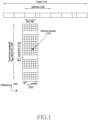
- FIG. 1 illustrates the basic structure of a time-frequency resource domain of a 5G system according to an embodiment of the disclosure. That is, FIG. 1 illustrates the basic structure of a time-frequency resource domain which is a radio resource domain used to transmit data or control channels in a 5G system.
- the basic unit of a resource in the time-frequency domain is a resource element (RE) 112, which may be described by an OFDM symbol index and a subcarrier index.
- a resource block (RB) or a physical resource block (PRB) may be defined by N sc RB consecutive subcarriers 110 in the frequency domain.
- N sc RB 12
- the data rate may increase in proportion to the number of RBs scheduled for a UE.
- a gNB may map data at the RB level, and may generally schedule RBs constituting one slot with regard to a specific UE. That is, the basic time unit to perform scheduling in 5G systems may be a slot, and the basic frequency unit to perform scheduling may be an RB.
- the extended CP is applied to a system having a larger radio-wave transmission distance than the normal CP, thereby maintaining orthogonality between symbols. In the case of the normal CP, the ratio between the CP length and the symbol length may be maintained constant such that overhead caused by the CP is maintained constant regardless of the subcarrier spacing.
- the subcarrier spacing, the CP length, and the like correspond to information indispensable to OFDM transmission/reception, and a gNB and a UE need to recognize the subcarrier spacing, the CP length, and the like as mutually common values such that efficient transmission/reception is possible.
- [Table 1] describes the relationship between the subcarrier spacing configuration ( ⁇ ), the subcarrier spacing ( ⁇ f), and the CP length supported in 5G systems.
- ⁇ ⁇ f 2 ⁇ ⁇ 15[kHz] Cyclic prefix 0 15 Normal 1 30 Normal 2 60 Normal, Extended 3 120 Normal 4 240 Normal
- [Table 2] enumerates the number ( N symb slot ) of slots per one slot, the number of slots ( N slot frame , ⁇ ) per one frame, and the number ( N slot subframe , ⁇ ) of slots per one subframe, with regard to each subcarrier spacing configuration ( ⁇ ), in the case of a normal CP.
- [Table 2] ⁇ 0 14 10 1 1 14 20 2 2 14 40 4 3 14 80 8 4 14 160 16
- [Table 3] enumerates the number ( N symb slot ) of slots per one slot, the number of slots ( N slot frame , ⁇ ) per one frame, and the number ( N slot subframe , ⁇ ) of slots per one subframe, with regard to each subcarrier spacing configuration ( ⁇ ), in the case of an extended CP. [Table 3] ⁇ 2 12 40 4
- frame structure B two slots may constitute one subframe, and 20 subframes may constitute one frame.
- the subcarrier spacing, the CP length, the slot length, and the like are integer multiples with each other with regard to each frame structure, thereby providing a high degree of extendibility.
- a subframe having a fixed length of 1ms may be defined to represent a reference time unit unrelated to the frame structure.
- the frame structure of 5G systems may be applied according to various scenarios.
- the larger the cyclic prefix (CP) length the larger cells can be supported. Therefore, frame structure A can support larger cells than frame structure B.
- the larger the subcarrier spacing the more advantageous for restoration of phase noise in high-frequency bands. Therefore, frame structure B can support higher operating frequencies than frame structure A.
- the uplink may refer to a radio link via which a user equipment transmits data or control signals to a base station
- the downlink may refer to a radio link via which the base station transmits data or control signals to the user equipment
- the user equipment may perform downlink time and frequency domain synchronization and acquire a cell identifier (ID) from a synchronization signal, transmitted by a base station, through a cell search.
- the user equipment may receive a physical broadcast channel (PBCH) by using the acquired cell ID and acquire a master information block (MIB) as mandatory system information from the PBCH.
- the user equipment may receive system information (system information block (SIB)) transmitted by the base station to acquire cell-common transmission and reception-related control information.
- SIB system information block
- the cell-common transmission and reception-related control information may include random access-related control information, paging-related control information, common control information for various physical channels, etc.
- a synchronization signal is a signal that serves as a reference for a cell search, and for each frequency band, a subcarrier spacing may be applied adaptively to a channel environment, such as phase noise. For a data channel or a control channel, in order to support various services as described above, a subcarrier spacing may be applied differently depending on a service type.
- FIG. 2 illustrates an example of a beam sweeping operation and a time domain mapping structure of a synchronization signal
- FIG. 2 illustrates an example in which beam sweeping is applied in units of SS/PBCH blocks over time.
- UE 1 205 receives an SS/PBCH block by means of a beam emitted in direction #d0 201 by beamforming applied to SS/PBCH block #0 at time point t1 203.
- UE 2 206 receives an SS/PBCH block by means of a beam emitted in direction #d4 202 by beamforming applied to SS/PBCH block #4 at time point t2 204.
- the UE may acquire, from the base station, an optimal synchronization signal via a beam emitted in the direction where the UE is located. For example, it may be difficult for UE 1 205 to acquire time/frequency synchronization and mandatory system information from the SS/PBCH block through the beam emitted in direction #d4 far away from the location of UE 1.
- the UE may also receive the SS/PBCH block. Furthermore, during a handover procedure in which the UE moves access from the current cell to an adjacent cell, the UE may receive an SS/PBCH block of the adjacent cell in order to determine the radio link quality of the adjacent cell and acquire time/frequency synchronization with the adjacent cell.
- the UE may perform a random access procedure in order to switch a link to the base station to a connected state (or RRC _CONNECTED state).
- a connected state or RRC _CONNECTED state.
- the UE switches to a connected state in which one-to-one communication between the base station and the UE is possible.
- a random access procedure will be described with reference to FIG. 3 .
- FIG. 3 illustrates an example of a random access procedure.
- the UE may transmit a random access preamble to the gNB.
- the random access preamble is the first message transmitted by the UE in the random access procedure, and thus may be referred to as message 1.
- the gNB may measure the transmission delay value between the UE and the gNB from the random access preamble, and may make uplink synchronization.
- the UE may then arbitrarily select the random access preamble to be used, from a random access preamble set given by system information in advance.
- the initial transmission power of the random access preamble may be determined by the pathloss between the gNB and the UE, measured by the UE.
- the UE may also determine the transmission beam direction of the random access preamble from a synchronization signal received from the gNB and then transmit the random access preamble.
- gNB transmits an uplink transmission timing adjustment command to the UE, based on a transmission delay value measured from the random access preamble received in the first step 310.
- the gNB may also transmit a power control command and an uplink resource to be used by the UE, as scheduling information.
- the scheduling information may include control information regarding the UE's uplink transmission beam.
- the UE may perform the first step 310 again.
- the UE may transmit the random access preamble after increasing the transmission power thereof by a predetermined step (power ramping), thereby increasing the probability that the gNB will receive the random access preamble.
- the UE transmits uplink data (message 3) including the UE's ID to the gNB through a physical uplink shared channel (PUSCH) by using the uplink resource allocated thereto in the second step 320.
- the transmission timing of the PUSCH for transmitting message 3 may follow the timing control command received from the gNB in the second step 320.
- the transmission power of the PUSCH for transmitting message 3 may be determined in consideration of a power control command received from the gNB in the second step 320 and the random access preamble's power ramping value.
- the PUSCH for transmitting message 3 may refer to the first uplink data signal transmitted to the gNB by the UE, after transmission of the random access preamble by the UE.
- the gNB transmits data (message 4) including the ID of the UE which transmitted uplink data in the third step 330 to the corresponding UE.
- the UE may determine that the random access has succeeded.
- the UE may then transmit HARQ-ACK information to the gNB through a physical uplink control channel (PUCCH) to indicate whether or not message 4 has been received successfully.
- PUCCH physical uplink control channel
- the gNB may no longer transmit data to the UE. If the UE thus fails to receive data transmitted from the gNB in the fourth step 340 within a predetermined time, the UE may determine that the random access procedure has failed and may restart from the first step 310.
- the UE Upon successfully completing the random access procedure, the UE is switched to a connected state, and one-to-one communication between the gNB and the UE becomes possible.
- the gNB may receive UE capability information reported by the UE in the connected state, and may adjust the scheduling with reference to the UE capability information from the UE.
- the UE may inform the gNB whether the UE itself supports a specific function or not, the maximum allowed value of the function supported by the UE, and the like through the UE capability information. Therefore, UE capability information reported to the gNB by each UE may have a different value with regard to each UE.
- the UE may report UE capability information including at least one of the following pieces of control information as UE capability information to the gNB.
- FIG. 4 illustrates an example of a procedure in which a UE reports UE capability information to a gNB.
- the gNB 402 may transmit a UE capability information request message to the UE 401 in step 410.
- the UE transmits UE capability information to the gNB in step 420 at the request for UE capability information of the gNB.
- the UE connected to the gNB may conduct one-to-one communication as a UE in an RRC CONNECTED state.
- the UE having no connection may be a UE in an RRC_IDLE state, and operations of the UE in the RRC_IDLE state may be distinguished as follows. Obviously, the following example is not limitative.
- RRC_INACTIVE a new UE state referred to as RRC_INACTIVE has been defined to reduce the energy and time consumed for the UE's initial access.
- the RRC _INACTIVE UE may perform the following operations in addition to operations performed by an RRC_IDLE UE. Obviously, the following example is not limitative.
- Downlink control information refers to control information transmitted to from the gNB to a UE through the downlink, and may include downlink data scheduling information or uplink data scheduling information regarding a specific UE.
- the gNB may independently channel-code DCI with regard to each UE and may transmit the same to each UE through a physical downlink control channel (PDCCH).
- PDCCH physical downlink control channel
- the gNB may apply and operate a predetermined DCI format according to the purpose, such as whether the same is scheduling information regarding downlink data (downlink assignment), whether the same is scheduling information regarding uplink data (uplink grant), or whether the same is DCI for power control.
- the gNB may transmit downlink data to the UE through a physical downlink shared channel (PDSCH).
- Scheduling information such as detailed mapping locations in time and frequency domains of the PDSCH, the modulation scheme, HARQ-related control information, and power control information, may be provided from the gNB to the UE through DCI related to downlink data scheduling information among DCI transmitted through a PDCCH.
- the UE may transmit uplink data to the gNB through a physical uplink shared channel (PUSCH).
- Scheduling information such as detailed mapping locations in time and frequency domains of the PUSCH, the modulation scheme, HARQ-related control information, and power control information, may be provided from the gNB to the UE through DCI related to uplink data scheduling information among DCI transmitted through a PDCCH.
- the time-frequency resource to which the PDCCH is mapped is referred to as a control resource set (CORESET).
- the CORESET may be configured in all or part of frequency resources in a bandwidth supported by the UE in the frequency domain.
- One or multiple OFDM symbols may be configured as the same in the time domain, and this may be defined as a control resource set (CORESET) duration.
- the gNB may configure one CORESET or multiple CORESETs for the UE through upper layer signaling (for example, system information, master information block (MIB), radio resource control (RRC) signaling).
- the description that a CORESET is configured for the UE may mean that information such as the CORESET identity, the CORESET's frequency location, and the CORESET's symbol length is provided thereto.
- Pieces of information provided from the gNB to the UE to configure a CORESET may include at least a part of the information included in [Table 4] below:
- a CORESET may be configured by N RB CORESET RBs in the frequency domain and N symb CORESET ⁇ 1 2,3 symbols in the time domain.
- An NR PDCCH may be configured by one or multiple control channel elements (CCEs).
- CCE may be configured by six resource element groups (REGs), and each REG may be defined as one RB during one OFDM symbol.
- REGs may be indexed in the time-first order, starting from REG index 0 in the CORESET's first CORESET symbol/lowest RB.
- the UE may determine a CCE-to-REG mapping type in the corresponding CORESET as in [Table 5] below: [Table 5]
- the CCE-to-REG mapping for a control-resource set can be interleaved or non-interleaved and is described by REG bundles: - REG bundle i is defined as REGs ⁇ iL , iL +1....
- the gNB may provide the UE with configuration information regarding to which symbol the PDCCH is mapped in the slot, the transmission period, and the like through signaling.
- the search space is a set of downlink control channel candidates including CCEs which the UE needs to attempt to decode at a given AL, and since 1, 2, 4, 8, or 16 CCEs may constitute a bundle at various ALs, the UE may have multiple search spaces.
- a search space set may be defined as a set of search spaces at all configured ALs.
- Configuration information of the search space for the PDCCH may be configured for the UE by the base station through upper layer signaling (e.g., SIB, MIB, or RRC signaling).
- the base station may provide the UE with configurations such as the number of PDCCH candidates at each aggregation level L, the monitoring cycle regarding the search space, the monitoring occasion with regard to each symbol in a slot regarding the search space, the search space type (common search space or UE-specific search space), a combination of an RNTI and a DCI format to be monitored in the corresponding search space, a control resource set index for monitoring the search space, and the like.
- parameters of the search space for the PDCCH may include the following pieces of information given in Table 6 below.
- the base station may configure one or multiple search space sets for the UE.
- the base station may configure search space set 1 and search space set 2 for the UE.
- search space set 1 the UE may be configured to monitor DCI format A scrambled by an X-RNTI in a common search space
- search space set 3 the UE may be configured to monitor DCI format B scrambled by a Y-RNTI in a UE-specific search space.
- one or multiple search space sets may exist in a common search space or a UE-specific search space.
- search space set #1 and search space set #2 may be configured as a common search space
- search space set #3 and search space set #4 may be configured as a UE-specific search space.
- the UE may monitor combinations of DCI formats and RNTIs given below. Obviously, the example given below is not limiting.
- the UE may monitor combinations of DCI formats and RNTIs given below. Obviously, the example given below is not limiting.
- RNTIs enumerated above may follow the definition and usage given below.
- DCI formats enumerated above may follow the definitions given in Table 7 below.
- Table 7 DCI format Usage 0_0 Scheduling of PUSCH in one cell 0_1 Scheduling of PUSCH in one cell 1_0 Scheduling of PDSCH in one cell 1_1 Scheduling of PDSCH in one cell 2_0 Notifying a group of UEs of the slot format 2_1 Notifying a group of UEs of the PRB(s) and OFDM s ymbol(s) where UE may assume no transmission is inte nded for the UE 2_2 Transmission of TPC commands for PUCCH and PUSC H 2_3 Transmission of a group of TPC commands for SRS tr ansmissions by one or more UEs
- the search space at aggregation level L in connection with CORESET p and search space set s may be expressed by the following equation. L ⁇ Y p , n s , f ⁇ + m s , n CI ⁇ N CCE , p L ⁇ M s , max L + n CI mod N CCE , p L + i
- signal transmission/reception in super-broad bandwidths ranging from tens or hundreds of MHz or multiple GHz may be supported to accomplish a super-fast data service at multiple Gbps in 5G systems.
- Signal transmission/reception in super-broad bandwidths may be supported through a single component carrier (CC) or through a carrier aggregation (CA) technology which combines multiple CCs. If the mobile communication operator fails to secure frequencies in a bandwidth enough to provide a super-fast data service by using a single CC, the CA technology combines respective CCs having a relatively small bandwidth size such that the total sum of frequency bandwidths is increased, consequently enabling a super-fast data service.
- CC component carrier
- CA carrier aggregation
- 5G systems are designed and developed in consideration of all of various use cases. Besides the standby time, reliability, and availability, the UE's energy efficiency is critical in 5G systems. 5G UEs need to be charged on a weekly or daily basis according to the individuals' time of use. In general, 5G UEs consume tens of mW in RRC _IDLE/RRC_INACTIVE states, and consume hundreds of mW in RRC_CONNECTED states. Design for extending the battery life is an indispensable element not only for better user experiences, but also for improved energy efficiency. Energy efficiency is more important to UEs having no continuous energy supply, for example, UEs using small rechargeable and single coin cell batteries.
- sensors and actuators are arranged for monitoring, measurement, charging, and the like on a wide scale.
- batteries for sensors or actuators cannot be recharged, and are expected to last at least a number of years.
- wearable devices such as smartwatches, rings, eHealth-related devices, and medical monitoring devices can hardly last a maximum of 1-2 weeks, depending on the time of use.
- a 5G UE's power consumption depends on the configured length of wakeup periods, for example, the paging cycle, and it is expected that an extended discontinuous reception (eDRX) cycle having a large value will be used to satisfy battery lifetime requirements.
- the eDRX scheme maintains a long battery lifetime on the basis of a long standby time, and thus is inappropriate for a service having a short standby time.
- it is within 1-2 seconds from the timepoint at which a fire is sensed by a sensor that fire shutters need to be closed, and sprinklers need to be activated by actuators. That is, in a use case having a critical standby time, a long eDRX cycle as in existing cases cannot satisfy latency requirements, and the eDRX is thus inappropriate for such a case.
- a 5G UE may need to periodically wake up once per eDRX cycle, and this may dominate power consumption during a period of time having no signaling or data traffic. Power consumption could be substantially reduced if the UE could wake up only when triggered (for example, through paging). This may be accomplished by a method, as in FIG. 5 , wherein the main radio (existing NR radio) is triggered by using a wake-up signal (WUS), and the main radio is turned on only when data transmission/reception is necessary by using a wake-up receiver (WUR) which is a separate receive capable of monitoring the WUS with super-low power.
- WUS wake-up signal
- WUR wake-up receiver
- the UE receives the WUS by using the WUR 502. According to whether the received signal is ON or OFF information, the main radio 504 in an ON or OFF state is triggered (503), thereby configuring a state in which the same is woken up or powered off. Depending on the case, the UE may configure the main radio 504 to be in a deep sleep state without fully turning off the same.
- the main radio is turned on 506, and the UE receives data sent by the gNB through the main radio (not through the WUR).
- Power consumed by monitor the WUS depends on design of the WUS design and hardware modules of the WUR used to detect and process signals, and it is thus expected that the gain will be maximized with regard to devices which are sensitive to power and have small form factors, including wearable devices, and IoT use cases (such as industrial sensors and controllers), in particular.
- a UE having the above-described structure additionally needs WUR-related states in addition to existing RRC states (RRC _CONNECTED, RRC_INACTIVE, RRC _IDLE) limited to the main radio.
- RRC states RRC _CONNECTED, RRC_INACTIVE, RRC _IDLE
- states of the WUR are determined due to a low-latency/low-power technique that uses the WUS, the state regarding the main radio may be changed, and the relationship between the WUR state and the main radio state also needs to be redefined.
- the UE's WUR state is divided, and operations of the UE during a state transition will be described.
- the UE' s WUR state may be divided into a single state, a dual state, and a multi-state according to the frequency at which the WUR is turned on, and respective states will be described in detail with reference to FIG. 6 to FIG. 8 .
- FIG. 6 illustrates the UE's WUR in a single state.
- the WUR may be always turned on (601). Since the WUR is always turned on (601), the WUR may always monitor a WUS regardless of the UE's main radio's state (RRC_INACTIVE, RRC_IDLE, RRC_CONNECTED) or without being affected by the main radio's state. There is substantially no need to define additional states regarding the WUR if the single state is reached.
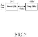
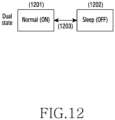
- FIG. 7 illustrates a state transition when the UE's WUR is in a dual state.
- the WUR is in an ON state 701 only when a WUS needs to be received from the gNB, and is on an OF state 702 in other cases.
- it may be determined whether the WUR's state may be an ON state 701 or an OFF state 702 according to whether the main radio can receive data or not. For example, in a situation in which the main radio is receiving data as indicated 505 in FIG. 5 , the WUR may maintain an OFF state 702.
- the WUR may maintain an ON state 701 through a process 703 only when receiving the WUS 501 in FIG. 5 in order to turn off the main radio because data reception is over, or to induce a deep sleep state thereof. Therefore, compared with the single state, the WUR's power may be saved during the time corresponding to the OFF state, and the UE's more power saving may thus be possible.
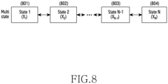
- FIG. 8 illustrates a state transition when the UE's WUR is in a multi-state.
- an additional state may be necessary if it is expected that no WUS will be received for a long period of time, for example, IoT for distribution checkup, at a specific timepoint.
- N states may be defined according to the frequency at which the WUS is received, as indicated by 801 to 804. Assuming that the frequency at which the WUS is received in the n th state is X n , it is possible to apply and operate X n values which may be predefined or upper-layer-configured by the gNB, such as X 1 >X 2 >..,>X N-1 >X N .
- Each state may transition only to an adjacent state, as in the multi-state in FIG. 7 , or may transition to states other than adjacent states, depending on the case, under the determination by the gNB or UE. Names given above with reference to FIG. 6 to FIG. 8 are only examples, and each UE's WUR states may be described differently.
- the main radio's state is divided in a state in which the UE's WUR state is defined, and operations of the UE during a state transition will be described.
- the UE's main radio state may be largely divided in two methods. Respective states in the first method which involves no redefinition will be described in detail with reference to FIG. 9 and FIG. 10 , and respective states in the second method which involves redefinition will be described in detail with reference to FIG. 11 to FIG. 13 .
- FIG. 9 illustrates the UE main radio's state, which remains an existing RRC state, as states of the WUR are determined due to a low-latency/low-power technique that uses a WUS.
- the RRC _CONNECTED 903 UE has completed an initial access procedure such that one-to-one communication between the gNB and the UE is possible, but the RRC_INACTIVE 902 UE or RRC_IDLE 901 UE mainly performs an operation of receiving cell-common control information such as the gNB's system information or paging messages. Channels available for transmission/reception are limited according to the UE's state.
- the main radio may convert to the RRC_INACTIVE 902 or RRC_IDLE 901 state and transition to a sleep mode (deep sleep, light sleep, micro sleep, or the like) according to the UE's determination.
- the gNB recognizes that the UE's state is only RRC_INACTIVE 902 or RRC _IDLE 901 state as in existing cases, and the UE may operate as defined by specifications for the sake of RRC_INACTIVE 902 or RRC IDLE 901.
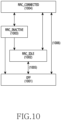
- FIG. 10 illustrates the UE main radio's state, which remains an existing RRC state, as states of the WUR are determined due to a low-latency/low-power technique that uses a WUS, as well as an additional OFF state 1001 defined therefor.
- existing RRC states 1002 to 1004 are used before the WUR receives a WUS that indicates the OFF state of the main radio from the gNB, and are transitioned to the OFF state 1001 after the WUS is received. That is, a mode in which the UE performs no operation and consumes only standby power for the sake of the UE's power saving is referred to as the OFF state 1001.
- the UE's main radio operates in the OFF state 1001
- the same does not receive any gNB system information and related control channels, except for the WUS.
- the UE's substantial state or information is stored in the lastly connected gNB, and if the UE's WUR receives a WUS corresponding to the ON state, the same may return to the lastly connected gNB in the RRC_IDLE 1002 state and may receive cell-common control information such as system information of the gNB or paging messages (1005), or may undergo a state transition 1006 back to RRC _CONNECTED through a random access.
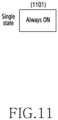
- FIG. 11 illustrates the UE main radio state, which is redefined as a single state, as states of the WUR are determined due to a low-latency/low-power technique that uses a WUS. If the UE's main radio is in the single state, the same is always turned on (1101), and the largest amount of power is consumed in this scenario, which may thus be applied only when the UE's power consumption is not a problem.
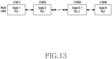
- FIG. 13 illustrates the UE main radio state, which is redefined as a multi-state, as states of the WUR are determined due to a low-latency/low-power technique that uses a WUS.
- K steps 1301 to 1304 may be defined, instead of two steps of ON/OFF, with reference to the time for which the main radio may continuously sleep, the power-saving level at which RF components may be turned off, or the energy harvesting level, for example.
- the sleep level of the k th state is X k
- predefined X k values may be applied and operated such as X 1 >X 2 >...>X K-1 >X K .
- Each state may transition only to an adjacent state, as in the multi-state in FIG. 13 , or may transition to states other than adjacent states, depending on the case, under the determination by the gNB or UE. Names given above with reference to FIG. 9 to FIG. 13 are only examples, and each UE's main radio states may be described differently.
- the WUR state is always ON, as in FIG. 6 , regardless of the main radio's state, all states of the main radio may be connected to, according to which WUS is received. Therefore, the WUS may include information indicating all states of the main radio.
- the WUR has very low power, but continuously wastes power. Therefore, it will be assumed in following descriptions with reference to FIG. 14 and FIG. 15 that the WUR has two or more states.
- FIG. 14 illustrates the relation between two states when the WUR and the main radio both have a dual state of ON/OFF.
- the WUR's state may be the opposite of the main radio's state, based on the main radio's state. That is, the WUR's state may be implicitly determined from the main radio's state. For example, in a situation in which the main radio is receiving data, the WUR may maintain the OFF state 1401 if the main radio is turned on (1404). If the main radio reaches an idle state after finishing receiving data, the WUR reaches an ON state 1402 after a predetermined time, and the main radio reaches an OFF state 1403. If traffic occurs again and thus requires data transmission, a WUS corresponding to an ON state is first received through the WUR, and main radio ON 1404 is then triggered (1405), thereby turning on the main radio.
- the gNB may transmit a WUS corresponding to an OFF state in order to turn off the main radio or to send the same to a deep sleep state in the above case.
- the WUR 1402 in an ON state triggers (1406) main radio OFF, and the main radio reaches an OFF state 1403. It may be implied that, if the WUR's state transition from the OFF state 1401 to the ON state 1402 without the gNB's intervention is not clear, the gNB will not depend on the WUS/WUR. Thereafter, the WUR maintains the OFF state 1401, and the main radio may perform legacy operations (RRC states).
- RRC states legacy operations
- the difference in the two cases lies whether the gNB intervenes or not in connection with turning off the main radio or sending the same to a deep sleep state, although waking up the main radio is identically triggered by a WUS.
- FIG. 15 illustrates the relation between two states when the WUR has a dual state of ON/OFF, and the main radio maintains an existing RRC state.
- the example in FIG. 15 corresponds to a situation in which the main radio maintains an RRC state of existing specifications, and only WUR states are added.
- the WUR's OFF state 1501 is connected to the main radio's RRC_CONNECTED state 1503, and the ON state 1502 thereof may be connected to the main radio's RRC_INACTIVE 1504 and RRC_IDLE state 1505.
- the ON state 1502 may be connected to the main radio's RRC _CONNECTED 1503.
- the main radio additionally has an OFF state 1506 as described with reference to FIG. 10
- the main radio's OFF state 1506 is also connected to the WUS's ON state 1502.
- the WUR may maintain the ON state for the fallback purpose, in some cases. That is, even if the WUR can go to the OFF state in FIG. 14 , the WUR may maintain the ON state, or the ON state may be triggered, in specific cases. For example, it may be assumed that a gNB informs a UE of a handover. Then, the WUR may be maintained in the ON state for the purpose of waking up the main radio for the sake of a handover between gNB no. 1 which supports the WUR and gNB no. 2 which does not support the WUR. As another example, if the main radio's wake time is periodically configured by the gNB (for example, if the main radio needs to periodically receive data), the WUR may automatically wake up the main radio according to the period.
- the UE needs to sense the paging situation with regard to each DRX period for paging message and system information updates, and the frequency (parameter) at which the WUS is received in each state of the WUR plays the same role as the DRX period.
- FIG. 16 illustrates a UE's generalized procedure in a state transition process for the UE's main radio operation.
- the gNB transmits a WUS for triggering the main radio's ON because the UE's RRC_CONNECTED state or the main radio's reception is necessary.
- the WUS for triggering the main radio's ON may include simple information for simply triggering the main radio's ON, or may express information which may be mapped to the WUR multi-state in FIG. 8 or to the main radio's multi-state, thereby expressing various states.
- the gNB may transmit information to the UE to indirectly indicate that the main radio needs to be ready to receive data at a timepoint at least at which data transmission is necessary, by adjusting the ON frequency of the main radio or the sleep mode thereof.
- the UE may receive a WUS by the WUR so as to identify which operation is indicated by the WUS.
- the UE performs a trigger such that the main radio can operate through the received WUS.
- the trigger performed by the UE for the main radio's operation may differ depending on the main radio's state expression. Firstly, in a case in which the existing RRC state is maintained as in FIG. 9 to FIG. 10 , a trigger is performed such that an RRC_CONNECTED is reached through a random access because the UE's main radio is in the RRC_INACTIVE or RRC_IDLE or OFF state. Alternatively, in a case in which the UE's main radio is in the RRC_CONNECTED state, there may be no need to perform a random access, and step 1603 may thus be omitted.
- the UE may likewise perform a trigger such that an ON state is reached through a random access or in the case of a multi-case, in particular, may perform a trigger such that a random access can be made after timepoint X k .
- the UE performs a random access according to the trigger timepoint in step 1602.
- the random access varies depending on the state defined in the main radio, such as RRC _INACTIVE, RRC _IDLE, or the like.
- Msg3 may include RRCResumeRequest in order to go to RRC_CONNECTED, and in the case of RRC_IDLE or OFF, RRCSetupRequest may be included.
- Msg3 includes EstablishmentCause which indicates the reason to change to the RRC _CONNECTED or ON state, and an additional message may need to be defined to indicate a trigger by the WUR because it is not an existing paging operation.
- the UE may change to an appropriate state if the WUR's state change is necessary after a change to the RRC _CONNECTED or ON state as a result of a random access normally performed by the main radio.
- Step 1406 may be omitted if the WUR is always in the ON state as in FIG. 6 .
- such a state change may be necessary if the WUR is changed to the opposite state of the main radio's state. If the WUR is changed to the opposite state of the main radio's state, signaling with the gNB is not necessary because such an operation is generally performed inside the UE. However, the UE may inform the gNB of the WUR's state because a signal regarding the UE's main radio operation suspension may be received through a WUS.
- Operations between the UE and the gNB from step 1605 are identical to existing operations.
- UEs Upon receiving gNB state transition signaling, UEs operate according to parameters configured by the gNB and receive data.
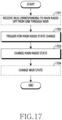
- FIG. 17 illustrates a UE's generalized procedure in a state transition process for the UE's main radio operation suspension.
- the gNB may transmit a WUS for triggering the UE's RRC_IDLE/RRC_INACTIVE or the main radio's OFF state such that the UE reaches the RRC _IDLE/RRC_INACTIVE or the main radio reaches the OFF state.
- the WUS for triggering the UE's RRC_IDLE/RRC_INACTIVE or the main radio's OFF state may include simple information for simply indicating the main radio's OFF, or may express information which may be mapped to the WUR multi-state in FIG. 8 , thereby expressing various states.
- the UE may adjust the main radio's state by adjusting the frequency.
- the UE may receive a WUS that triggers the UE's RRC IDLE/RRCINACTIVE or the main radio's OFF state through the WUR so as to identify which operation is indicated by the WUS. If the WUR has been turned off, the UE may operate the main radio in existing RRC states.
- the UE may trigger an operation in which the main radio can change the state through the received WUS. Since the UE's main radio is in the RRC_CONNECTED state or ON state, the UE performs a trigger such that the same can remain in the RRC_INACTIVE or RRC_IDLE or OFF state. Alternatively, the UE's main radio may maintain the RRC _CONNECTED state. In existing operations, an RRC message referred to as RRCRelease has been received from the gNB for a state change to RRC _INACTIVE or RRC _IDLE, and in step 1702, the UE may determine that an RRC message such as RRCRelease has been indicated indirectly through a WUS. Similarly to step 1602, if the main radio is in a multi-state, the UE may perform a trigger such that a state transition can occur after timepoint X k .
- the main radio's state may be normally changed to the RRC _INACTIVE or RRC _IDLE state or quasi-OFF state.
- the WUR's state change may be performed in a state in which the main radio's state is normally changed to the RRC_INACTIVE or RRC_IDLE state or quasi-OFF state. Step 1704 may be omitted if the WUR is always in the ON state as in FIG. 6 . However, the WUR's state change is necessary if the WUR is changed to the opposite state of the main radio's state. The UE needs no additional signaling with the gNB because the gNB has already indirectly informed of RRCRelease through a WUS as in step 1701.
- the disclosure may also be performed by omitting the above-described steps in FIG. 16 and FIG. 17 , changing the order thereof, or adding undescribed steps.
- Existing embodiments have mainly considered cases in which the gNB recognizes the main radio's state, and a state transition to the opposite state, for example, is necessary.
- This embodiment considers an additional case in which a WUS in the same state as the main radio comes in. For example, if the WUR is configured in an ON state and is ready to receive a WUS, and if the main radio is ON, the gNB sends a WUS indicating an OFF state such that the UE's main radio transitions to the OFF state (or RRC INACTIVE or RRC IDLE). Since the gNB is aware of the main radio's state, no WUS is sent to indicate the main radio's ON state, according to existing embodiments, if the main radio is in the ON state.
- a WUS may be sent to indicate the main radio's ON state, even if the main radio is in the ON state, in order to urge the main radio to be quickly ready to receive data because there is data to be transmitted urgently in the case of urgent termination of DRX, for example.
- a WUS indicating the main radio's OFF state may be received from the gNB. Since the gNB is aware of the main radio's state, no WUS is sent to indicate the main radio's OFF state, according to existing embodiments, if the main radio is in the OFF state. However, a WUS may be sent to indicate the main radio's OFF state, even if the main radio is in the OFF state, in order to inform without additional DCI that the main radio in the RRC_CONNECTED state is delaying PDCCH monitoring (for example, DCI 2_6), or to transition the state which has been maintained as RRC CONNECTED to RRC_INACTIVE/RRC_IDLE. That is, the WUS may be used to play a role comparable to that of RRCRelease.
- FIG. 18 is a block diagram illustrating a structure of a UE according to an embodiment of the disclosure.
- a UE of the disclosure may include a processor 1820, a transceiver 1800, and a memory 1810.
- components of the UE are not limited to the above-described example.
- the UE may include a larger or smaller number of components than the above-described components.
- the processor 1820, the transceiver 1800, and the memory 1810 may be implemented in the form of a single chip.
- the processor 1820 may control a series of processes so that the UE can operate according to the above-described embodiments of the disclosure.
- the processor 1820 may control the components of the UE in order to perform the methods for providing broadcast services according to the above-described embodiments.
- the processor 1820 may control the components of the UE to perform the embodiments of the disclosure by executing the programs stored in the memory 1810.
- the processor 1820 may be an application processor (AP), a communication processor (CP), a circuit, an application -specific circuit, or at least one processor.
- the transceiver 1800 may transmit/receive signals with network entities, other UEs, or base stations.
- the signals transmitted/received with network entities, other UEs, or base stations may include control information and data.
- the transceiver 1800 may include an RF transmitter configured to up-convert and amplify the frequency of transmitted signals, an RF receiver configured to low-noise-amplify received signals and down-convert the frequency thereof, and the like.
- this is only an embodiment of the transceiver 1800, and the components of the transceiver 1800 are not limited to the RF transmitter and the RF receiver.
- the transceiver 1800 may receive signals through a radio channel, output the same to the processor 1820, and transmit signals output from the processor 1820 through the radio channel.
- the memory 1810 may store programs and data necessary for operations of the UE.
- the memory 1810 may store control information or data included in signals transmitted/received by the UE.
- the memory 1810 may include storage media such as a ROM, a RAM, a hard disk, a CD-ROM, and a DVD, or a combination of storage media.
- the memory 1810 may include multiple memories.
- the memory 1810 may store programs for executing the above-described methods for providing broadcast services.
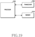
- FIG. 19 is a block diagram illustrating a structure of a base station according to an embodiment of the disclosure.
- a base station of the disclosure may include a processor 1920, a transceiver 1900, and a memory 1910.
- components of the base station are not limited to the above-described example.
- the base station may include a larger or smaller number of components than the above-described components.
- the processor 1920, the transceiver 1900, and the memory 1910 may be implemented in the form of a single chip.
- the processor 1920 may control a series of processes so that the base station can operate according to the above-described embodiments of the disclosure.
- the processor 1920 may control the components of the base station in order to provide broadcast services according to the above-described embodiments.
- the processor 1920 may control the components of the base station to perform the embodiments of the disclosure by executing the programs stored in the memory 1910.
- the processor 1920 may be an application processor (AP), a communication processor (CP), a circuit, an application -specific circuit, or at least one processor.
- the transceiver 1900 may transmit/receive signals with network entities, other base stations, or UEs.
- the signals transmitted/received with network entities, other base stations, or UEs may include control information and data.
- the transceiver 1900 may include an RF transmitter configured to up-convert and amplify the frequency of transmitted signals, an RF receiver configured to low-noise-amplify received signals and down-convert the frequency thereof, and the like.
- the transceiver 1900 may receive signals through a radio channel, output the same to the processor 1920, and transmit signals output from the processor 1920 through the radio channel.
- the memory 1910 may store programs and data necessary for operations of the base station.
- the memory 1910 may store control information or data included in signals transmitted/received by the base station.
- the memory 1910 may include storage media such as a ROM, a RAM, a hard disk, a CD-ROM, and a DVD, or a combination of storage media.
- the memory 1910 may include multiple memories.
- the memory 1910 may store programs for executing the above-described methods for providing broadcast services.
- a computer-readable storage medium for storing one or more programs (software modules) may be provided.
- the one or more programs stored in the computer-readable storage medium may be configured for execution by one or more processors within the electronic device.
- the at least one program includes instructions that cause the electronic device to perform the methods according to various embodiments of the disclosure as defined by the appended claims and/or disclosed herein.
- These programs may be stored in nonvolatile memories including a random access memory and a flash memory, a read only memory (ROM), an electrically erasable programmable read only memory (EEPROM), a magnetic disc storage device, a compact disc-ROM (CD-ROM), digital versatile discs (DVDs), or other type optical storage devices, or a magnetic cassette.
- ROM read only memory
- EEPROM electrically erasable programmable read only memory
- CD-ROM compact disc-ROM
- DVDs digital versatile discs
- any combination of some or all of them may form a memory in which the program is stored.
- a plurality of such memories may be included in the electronic device.
- the programs may be stored in an attachable storage device which can access the electronic device through communication networks such as the Internet, Intranet, Local Area Network (LAN), Wide LAN (WLAN), and Storage Area Network (SAN) or a combination thereof.
- a storage device may access the electronic device via an external port.
- a separate storage device on the communication network may access a portable electronic device.
- an element included in the disclosure is expressed in the singular or the plural according to presented detailed embodiments.
- the singular form or plural form is selected appropriately to the presented situation for the convenience of description, and the disclosure is not limited by elements expressed in the singular or the plural. Therefore, either an element expressed in the plural may also include a single element or an element expressed in the singular may also include multiple elements.
Landscapes
- Engineering & Computer Science (AREA)
- Computer Networks & Wireless Communication (AREA)
- Signal Processing (AREA)
- Mobile Radio Communication Systems (AREA)
Applications Claiming Priority (2)
| Application Number | Priority Date | Filing Date | Title |
|---|---|---|---|
| KR1020220079033A KR20240001997A (ko) | 2022-06-28 | 2022-06-28 | 무선 통신 시스템에서 웨이크업 수신기를 가진 단말의 파워 소모를 감소시키는 방법 및 장치 |
| PCT/KR2023/008756 WO2024005463A1 (ko) | 2022-06-28 | 2023-06-23 | 무선 통신 시스템에서 웨이크업 수신기를 가진 단말의 파워 소모를 감소시키는 방법 및 장치 |
Publications (2)
| Publication Number | Publication Date |
|---|---|
| EP4492876A1 true EP4492876A1 (de) | 2025-01-15 |
| EP4492876A4 EP4492876A4 (de) | 2025-05-07 |
Family
ID=89380845
Family Applications (1)
| Application Number | Title | Priority Date | Filing Date |
|---|---|---|---|
| EP23831823.2A Pending EP4492876A4 (de) | 2022-06-28 | 2023-06-23 | Verfahren und vorrichtung zur reduzierung des stromverbrauchs eines endgeräts mit aufweckempfänger in einem drahtloskommunikationssystem |
Country Status (4)
| Country | Link |
|---|---|
| US (1) | US20250267581A1 (de) |
| EP (1) | EP4492876A4 (de) |
| KR (1) | KR20240001997A (de) |
| WO (1) | WO2024005463A1 (de) |
Families Citing this family (1)
| Publication number | Priority date | Publication date | Assignee | Title |
|---|---|---|---|---|
| KR20250159989A (ko) * | 2024-05-03 | 2025-11-11 | 삼성전자주식회사 | 무선 통신 시스템에서 웨이크업 수신기를 가진 단말의 온 오프 동작 방법 및 장치 |
Family Cites Families (4)
| Publication number | Priority date | Publication date | Assignee | Title |
|---|---|---|---|---|
| CN107889199B (zh) * | 2016-09-30 | 2021-09-07 | 华为技术有限公司 | 一种状态转换方法及装置 |
| US11284372B2 (en) * | 2017-03-24 | 2022-03-22 | Apple Inc. | Wake up signal for machine type communication and narrowband-internet-of-things devices |
| US11564170B2 (en) * | 2017-05-04 | 2023-01-24 | Ipla Holdings Inc. | Wake up signals operation |
| KR20250048129A (ko) * | 2019-03-27 | 2025-04-07 | 텔레폰악티에볼라겟엘엠에릭슨(펍) | 저전력 블루투스에 의한 웨이크업 수신기의 사용 |
-
2022
- 2022-06-28 KR KR1020220079033A patent/KR20240001997A/ko active Pending
-
2023
- 2023-06-23 US US18/858,094 patent/US20250267581A1/en active Pending
- 2023-06-23 WO PCT/KR2023/008756 patent/WO2024005463A1/ko not_active Ceased
- 2023-06-23 EP EP23831823.2A patent/EP4492876A4/de active Pending
Also Published As
| Publication number | Publication date |
|---|---|
| WO2024005463A1 (ko) | 2024-01-04 |
| US20250267581A1 (en) | 2025-08-21 |
| KR20240001997A (ko) | 2024-01-04 |
| EP4492876A4 (de) | 2025-05-07 |
Similar Documents
| Publication | Publication Date | Title |
|---|---|---|
| EP4543100A1 (de) | Verfahren und vorrichtung zur verringerung des stromverbrauchs eines benutzergeräts mit aufweckempfänger in einem drahtloskommunikationssystem | |
| US20240236939A9 (en) | Method and apparatus for paging procedure in wireless communication system | |
| EP4496388A1 (de) | Verfahren und vorrichtung zur energieeinsparung eines drahtlosen kommunikationssystems | |
| US20250039788A1 (en) | Method and apparatus for reducing power consumption of user equipment having wake-up receiver in wireless communication system | |
| CN117981419A (zh) | 用于无线通信系统中基于寻呼子组的寻呼的方法和装置 | |
| US20240056965A1 (en) | Method and apparatus for wake-up receiving in wireless communication | |
| EP4492876A1 (de) | Verfahren und vorrichtung zur reduzierung des stromverbrauchs eines endgeräts mit aufweckempfänger in einem drahtloskommunikationssystem | |
| US20250063416A1 (en) | Method and apparatus for using measurement gap of ue having wake-up receiver in communication system | |
| EP4727220A1 (de) | Verfahren und vorrichtung zur funkverbindungsüberwachung durch ein endgerät mit aufweckempfänger in einem drahtloskommunikationssystem | |
| US20250133497A1 (en) | Method and apparatus for uplink transmission by user equipment having wake-up receiver in wireless communication system | |
| EP4622354A1 (de) | Verfahren und vorrichtung zur verringerung des stromverbrauchs eines benutzergeräts mit aufweckempfänger in einem drahtloskommunikationssystem | |
| US20250193796A1 (en) | Method and apparatus for determining bandwidth part of user equipment with wake-up receiver in wireless communication system | |
| US20260082326A1 (en) | Method and apparatus for receiving synchronization signal by user equipment having a wake-up receiver in a wireless communication system | |
| US20250159655A1 (en) | Method and apparatus of paging for user equipment receiving wake-up signal in wireless communication system | |
| EP4629703A1 (de) | Verfahren und vorrichtung zur verringerung der empfangsverzögerung eines benutzergeräts mit aufweckempfänger in einem drahtloskommunikationssystem | |
| US20250142472A1 (en) | Method and apparatus for measuring neighboring cell by user equipment having wake-up receiver in wireless communication system | |
| US20250070850A1 (en) | Method and apparatus for discontinuous transmission and reception of wireless communication system | |
| US20240381315A1 (en) | Method and device for paging for user equipment receiving wake-up signal in wireless communication system | |
| US20260046776A1 (en) | Method and apparatus for transmitting and receiving wake-up signal in wireless communication system | |
| EP4697816A1 (de) | Verfahren und vorrichtung zur verringerung des stromverbrauchs eines endgeräts mit aufweckempfänger in einem drahtloskommunikationssystem | |
| EP4482222A1 (de) | Verfahren und vorrichtung zur reduzierung des energieverbrauchs einer basisstation in einem drahtloskommunikationssystem | |
| KR20240177932A (ko) | 무선 통신 시스템에서 웨이크업 수신기를 가진 단말의 수신 방법 및 장치 | |
| KR20240175853A (ko) | 무선 통신 시스템에서 웨이크업 수신기를 가진 단말의 빔 수신 방법 및 장치 | |
| KR20250156369A (ko) | 무선 통신 시스템에서 웨이크업 수신기를 가진 단말의 파워 소모를 감소시키기 위한 방법 및 장치 | |
| KR20250036650A (ko) | 무선 통신 시스템에서 웨이크업 수신기를 가진 단말의 pei를 수신하기 위한 방법 및 장치 |
Legal Events
| Date | Code | Title | Description |
|---|---|---|---|
| STAA | Information on the status of an ep patent application or granted ep patent |
Free format text: STATUS: THE INTERNATIONAL PUBLICATION HAS BEEN MADE |
|
| PUAI | Public reference made under article 153(3) epc to a published international application that has entered the european phase |
Free format text: ORIGINAL CODE: 0009012 |
|
| STAA | Information on the status of an ep patent application or granted ep patent |
Free format text: STATUS: REQUEST FOR EXAMINATION WAS MADE |
|
| 17P | Request for examination filed |
Effective date: 20241011 |
|
| AK | Designated contracting states |
Kind code of ref document: A1 Designated state(s): AL AT BE BG CH CY CZ DE DK EE ES FI FR GB GR HR HU IE IS IT LI LT LU LV MC ME MK MT NL NO PL PT RO RS SE SI SK SM TR |
|
| A4 | Supplementary search report drawn up and despatched |
Effective date: 20250407 |
|
| RIC1 | Information provided on ipc code assigned before grant |
Ipc: H04W 76/27 20180101ALI20250401BHEP Ipc: H04W 52/02 20090101AFI20250401BHEP |
|
| DAV | Request for validation of the european patent (deleted) | ||
| DAX | Request for extension of the european patent (deleted) |