EP4492671A1 - Start-up device, motor system and method for reducing dc motor start-up current - Google Patents
Start-up device, motor system and method for reducing dc motor start-up current Download PDFInfo
- Publication number
- EP4492671A1 EP4492671A1 EP24187371.0A EP24187371A EP4492671A1 EP 4492671 A1 EP4492671 A1 EP 4492671A1 EP 24187371 A EP24187371 A EP 24187371A EP 4492671 A1 EP4492671 A1 EP 4492671A1
- Authority
- EP
- European Patent Office
- Prior art keywords
- motor
- switching element
- state
- time interval
- predetermined time
- Prior art date
- Legal status (The legal status is an assumption and is not a legal conclusion. Google has not performed a legal analysis and makes no representation as to the accuracy of the status listed.)
- Pending
Links
Images

Classifications
-
- H—ELECTRICITY
- H02—GENERATION; CONVERSION OR DISTRIBUTION OF ELECTRIC POWER
- H02P—CONTROL OR REGULATION OF ELECTRIC MOTORS, ELECTRIC GENERATORS OR DYNAMO-ELECTRIC CONVERTERS; CONTROLLING TRANSFORMERS, REACTORS OR CHOKE COILS
- H02P1/00—Arrangements for starting electric motors or dynamo-electric converters
- H02P1/16—Arrangements for starting electric motors or dynamo-electric converters for starting dynamo-electric motors or dynamo-electric converters
- H02P1/18—Arrangements for starting electric motors or dynamo-electric converters for starting dynamo-electric motors or dynamo-electric converters for starting an individual DC motor
-
- H—ELECTRICITY
- H02—GENERATION; CONVERSION OR DISTRIBUTION OF ELECTRIC POWER
- H02H—EMERGENCY PROTECTIVE CIRCUIT ARRANGEMENTS
- H02H7/00—Emergency protective circuit arrangements specially adapted for specific types of electric machines or apparatus or for sectionalised protection of cable or line systems, and effecting automatic switching in the event of an undesired change from normal working conditions
- H02H7/08—Emergency protective circuit arrangements specially adapted for specific types of electric machines or apparatus or for sectionalised protection of cable or line systems, and effecting automatic switching in the event of an undesired change from normal working conditions for dynamo-electric motors
- H02H7/0833—Emergency protective circuit arrangements specially adapted for specific types of electric machines or apparatus or for sectionalised protection of cable or line systems, and effecting automatic switching in the event of an undesired change from normal working conditions for dynamo-electric motors for electric motors with control arrangements
-
- H—ELECTRICITY
- H02—GENERATION; CONVERSION OR DISTRIBUTION OF ELECTRIC POWER
- H02H—EMERGENCY PROTECTIVE CIRCUIT ARRANGEMENTS
- H02H7/00—Emergency protective circuit arrangements specially adapted for specific types of electric machines or apparatus or for sectionalised protection of cable or line systems, and effecting automatic switching in the event of an undesired change from normal working conditions
- H02H7/08—Emergency protective circuit arrangements specially adapted for specific types of electric machines or apparatus or for sectionalised protection of cable or line systems, and effecting automatic switching in the event of an undesired change from normal working conditions for dynamo-electric motors
- H02H7/0833—Emergency protective circuit arrangements specially adapted for specific types of electric machines or apparatus or for sectionalised protection of cable or line systems, and effecting automatic switching in the event of an undesired change from normal working conditions for dynamo-electric motors for electric motors with control arrangements
- H02H7/0844—Fail safe control, e.g. by comparing control signal and controlled current, isolating motor on commutation error
-
- H—ELECTRICITY
- H02—GENERATION; CONVERSION OR DISTRIBUTION OF ELECTRIC POWER
- H02H—EMERGENCY PROTECTIVE CIRCUIT ARRANGEMENTS
- H02H7/00—Emergency protective circuit arrangements specially adapted for specific types of electric machines or apparatus or for sectionalised protection of cable or line systems, and effecting automatic switching in the event of an undesired change from normal working conditions
- H02H7/08—Emergency protective circuit arrangements specially adapted for specific types of electric machines or apparatus or for sectionalised protection of cable or line systems, and effecting automatic switching in the event of an undesired change from normal working conditions for dynamo-electric motors
- H02H7/085—Emergency protective circuit arrangements specially adapted for specific types of electric machines or apparatus or for sectionalised protection of cable or line systems, and effecting automatic switching in the event of an undesired change from normal working conditions for dynamo-electric motors against excessive load
-
- H—ELECTRICITY
- H02—GENERATION; CONVERSION OR DISTRIBUTION OF ELECTRIC POWER
- H02H—EMERGENCY PROTECTIVE CIRCUIT ARRANGEMENTS
- H02H7/00—Emergency protective circuit arrangements specially adapted for specific types of electric machines or apparatus or for sectionalised protection of cable or line systems, and effecting automatic switching in the event of an undesired change from normal working conditions
- H02H7/08—Emergency protective circuit arrangements specially adapted for specific types of electric machines or apparatus or for sectionalised protection of cable or line systems, and effecting automatic switching in the event of an undesired change from normal working conditions for dynamo-electric motors
- H02H7/085—Emergency protective circuit arrangements specially adapted for specific types of electric machines or apparatus or for sectionalised protection of cable or line systems, and effecting automatic switching in the event of an undesired change from normal working conditions for dynamo-electric motors against excessive load
- H02H7/0854—Emergency protective circuit arrangements specially adapted for specific types of electric machines or apparatus or for sectionalised protection of cable or line systems, and effecting automatic switching in the event of an undesired change from normal working conditions for dynamo-electric motors against excessive load responsive to rate of change of current, couple or speed, e.g. anti-kickback protection
-
- H—ELECTRICITY
- H02—GENERATION; CONVERSION OR DISTRIBUTION OF ELECTRIC POWER
- H02P—CONTROL OR REGULATION OF ELECTRIC MOTORS, ELECTRIC GENERATORS OR DYNAMO-ELECTRIC CONVERTERS; CONTROLLING TRANSFORMERS, REACTORS OR CHOKE COILS
- H02P1/00—Arrangements for starting electric motors or dynamo-electric converters
- H02P1/02—Details of starting control
- H02P1/022—Security devices, e.g. correct phase sequencing
-
- H—ELECTRICITY
- H02—GENERATION; CONVERSION OR DISTRIBUTION OF ELECTRIC POWER
- H02P—CONTROL OR REGULATION OF ELECTRIC MOTORS, ELECTRIC GENERATORS OR DYNAMO-ELECTRIC CONVERTERS; CONTROLLING TRANSFORMERS, REACTORS OR CHOKE COILS
- H02P6/00—Arrangements for controlling synchronous motors or other dynamo-electric motors using electronic commutation dependent on the rotor position; Electronic commutators therefor
- H02P6/20—Arrangements for starting
- H02P6/21—Open loop start
-
- H—ELECTRICITY
- H02—GENERATION; CONVERSION OR DISTRIBUTION OF ELECTRIC POWER
- H02P—CONTROL OR REGULATION OF ELECTRIC MOTORS, ELECTRIC GENERATORS OR DYNAMO-ELECTRIC CONVERTERS; CONTROLLING TRANSFORMERS, REACTORS OR CHOKE COILS
- H02P7/00—Arrangements for regulating or controlling the speed or torque of electric DC motors
- H02P7/06—Arrangements for regulating or controlling the speed or torque of electric DC motors for regulating or controlling an individual DC dynamo-electric motor by varying field or armature current
- H02P7/18—Arrangements for regulating or controlling the speed or torque of electric DC motors for regulating or controlling an individual DC dynamo-electric motor by varying field or armature current by master control with auxiliary power
- H02P7/24—Arrangements for regulating or controlling the speed or torque of electric DC motors for regulating or controlling an individual DC dynamo-electric motor by varying field or armature current by master control with auxiliary power using discharge tubes or semiconductor devices
- H02P7/28—Arrangements for regulating or controlling the speed or torque of electric DC motors for regulating or controlling an individual DC dynamo-electric motor by varying field or armature current by master control with auxiliary power using discharge tubes or semiconductor devices using semiconductor devices
-
- H—ELECTRICITY
- H02—GENERATION; CONVERSION OR DISTRIBUTION OF ELECTRIC POWER
- H02P—CONTROL OR REGULATION OF ELECTRIC MOTORS, ELECTRIC GENERATORS OR DYNAMO-ELECTRIC CONVERTERS; CONTROLLING TRANSFORMERS, REACTORS OR CHOKE COILS
- H02P7/00—Arrangements for regulating or controlling the speed or torque of electric DC motors
- H02P7/06—Arrangements for regulating or controlling the speed or torque of electric DC motors for regulating or controlling an individual DC dynamo-electric motor by varying field or armature current
- H02P7/18—Arrangements for regulating or controlling the speed or torque of electric DC motors for regulating or controlling an individual DC dynamo-electric motor by varying field or armature current by master control with auxiliary power
- H02P7/24—Arrangements for regulating or controlling the speed or torque of electric DC motors for regulating or controlling an individual DC dynamo-electric motor by varying field or armature current by master control with auxiliary power using discharge tubes or semiconductor devices
- H02P7/28—Arrangements for regulating or controlling the speed or torque of electric DC motors for regulating or controlling an individual DC dynamo-electric motor by varying field or armature current by master control with auxiliary power using discharge tubes or semiconductor devices using semiconductor devices
- H02P7/285—Arrangements for regulating or controlling the speed or torque of electric DC motors for regulating or controlling an individual DC dynamo-electric motor by varying field or armature current by master control with auxiliary power using discharge tubes or semiconductor devices using semiconductor devices controlling armature supply only
- H02P7/29—Arrangements for regulating or controlling the speed or torque of electric DC motors for regulating or controlling an individual DC dynamo-electric motor by varying field or armature current by master control with auxiliary power using discharge tubes or semiconductor devices using semiconductor devices controlling armature supply only using pulse modulation
-
- H—ELECTRICITY
- H02—GENERATION; CONVERSION OR DISTRIBUTION OF ELECTRIC POWER
- H02P—CONTROL OR REGULATION OF ELECTRIC MOTORS, ELECTRIC GENERATORS OR DYNAMO-ELECTRIC CONVERTERS; CONTROLLING TRANSFORMERS, REACTORS OR CHOKE COILS
- H02P7/00—Arrangements for regulating or controlling the speed or torque of electric DC motors
- H02P7/06—Arrangements for regulating or controlling the speed or torque of electric DC motors for regulating or controlling an individual DC dynamo-electric motor by varying field or armature current
- H02P7/18—Arrangements for regulating or controlling the speed or torque of electric DC motors for regulating or controlling an individual DC dynamo-electric motor by varying field or armature current by master control with auxiliary power
- H02P7/24—Arrangements for regulating or controlling the speed or torque of electric DC motors for regulating or controlling an individual DC dynamo-electric motor by varying field or armature current by master control with auxiliary power using discharge tubes or semiconductor devices
- H02P7/28—Arrangements for regulating or controlling the speed or torque of electric DC motors for regulating or controlling an individual DC dynamo-electric motor by varying field or armature current by master control with auxiliary power using discharge tubes or semiconductor devices using semiconductor devices
- H02P7/285—Arrangements for regulating or controlling the speed or torque of electric DC motors for regulating or controlling an individual DC dynamo-electric motor by varying field or armature current by master control with auxiliary power using discharge tubes or semiconductor devices using semiconductor devices controlling armature supply only
- H02P7/29—Arrangements for regulating or controlling the speed or torque of electric DC motors for regulating or controlling an individual DC dynamo-electric motor by varying field or armature current by master control with auxiliary power using discharge tubes or semiconductor devices using semiconductor devices controlling armature supply only using pulse modulation
- H02P7/291—Arrangements for regulating or controlling the speed or torque of electric DC motors for regulating or controlling an individual DC dynamo-electric motor by varying field or armature current by master control with auxiliary power using discharge tubes or semiconductor devices using semiconductor devices controlling armature supply only using pulse modulation with on-off control between two set points, e.g. controlling by hysteresis
Definitions
- the present invention relates to a motor control technology, and in particular to a start-up device for a DC motor, a motor system comprising the start-up device, a method for reducing DC motor start-up current, and a computer-readable storage medium with a computer program stored thereon for implementing the method.
- the start-up current of a brushed DC motor commonly has a relatively high peak value, typically multiple times higher than rated current. This necessitates the use of high-standard and high-quality electronic components (e.g. a metal-oxide-semiconductor field-effect transistor (MOSFET), a current sampling resistor, a protecting fuse and a wire gauge etc.), leading to product costs remaining high.
- MOSFET metal-oxide-semiconductor field-effect transistor
- a current sampling resistor e.g. a current sampling resistor
- protecting fuse and a wire gauge etc. e.g. a protecting fuse and a wire gauge etc.
- a start-up device for a DC motor comprising:
- the above start-up device further comprises an overcurrent protection component coupled between the DC power supply and the DC motor.
- the above start-up device further comprises a capacitor connected between positive and negative terminals of the DC motor to absorb electromagnetic pulse components generated by the DC motor.
- the switching element is a metal-oxide-semiconductor field-effect transistor (MOSFET) with its gate coupled to the control unit, one of its source and drain coupled to the positive or negative terminal of the DC motor, and the other coupled to ground.
- MOSFET metal-oxide-semiconductor field-effect transistor
- control unit causes the switching element to periodically switch between the ON state and the OFF state by applying a pulse width modulation (PWM) signal to the gate.
- PWM pulse width modulation
- a frequency of the pulse width modulation (PWM) signal is set such that a value of the start-up current at the start of the predetermined time interval is smaller than a first threshold value.
- a length of the predetermined time interval is set to be greater than a second threshold value, so that the value of the start-up current at the start of the predetermined time interval is greater than a value when the switching element begins to maintain the ON state.
- a motor system comprising:
- a method for reducing DC motor start-up current comprising:
- a computer-readable storage medium with a computer program stored thereon suitable for execution on a processor of a terminal device, the execution of the computer program enabling the steps of the method as described above to be performed.
- a and B coupled and “A coupled to B” denote the following circumstances: i) A and B have a direct electrical or mechanical connection, etc.; ii) A and B are electrically or mechanically connected through C, etc.
- first and second do not indicate the sequence of units in such aspects as time, space, size, etc., but are only used to distinguish between units.
- FIG. 1 shows a schematic block diagram of a start-up device for a DC motor according to some embodiments. It should be pointed out that, in addition to the units shown in FIG. 1 , the start-up device further includes other units essential for implementing the start-up function. However, for the sake of conciseness, the description of FIG. 1 only involves units that are directly related to the subject of reducing start-up current.
- the start-up device 10 shown in FIG. 1 includes a switching element 110 and a control unit 120.
- the positive and negative terminals of a DC motor 11 are coupled to a DC power supply 12 and the switching element 110, respectively.
- the switching element 110 may also be connected in series in other locations within a circuit L comprising the DC motor and the DC power supply 12.
- the switching element 110 may be located between the positive terminal of the DC motor 11 and the DC power supply 12.
- the control unit 120 is coupled to the control terminal of the switching element 110 to control the ON-OFF state of the switching element 110.
- the control unit 120 regulates the peak value of the start-up current (hereinafter referred to as the peak start-up current) Ip of the DC motor 11 by controlling the ON-OFF state of the switching element 110.
- the control unit 120 may cause the switching element 110 to periodically switch between an ON state and an OFF state to reduce the peak start-up current Ip flowing through the DC motor.
- the predetermined time interval Ts described herein corresponds to a start-up phase of the DC motor 11, and thus can be understood as a start-up period of the DC motor. After the start-up period is over, the control unit 120 will cause the switching element 110 to maintain the ON state.
- the switching element 110 is implemented using a metal-oxide-semiconductor field-effect transistor (MOSFET) with its gate coupled to the control unit 120, one of the source S and drain D coupled to the positive or negative terminal of the DC motor 11, and the other coupled to ground.
- MOSFET metal-oxide-semiconductor field-effect transistor
- FIG. 2 shows a schematic circuit diagram of a start-up device for a DC motor according to some other embodiments.
- the switching element is implemented using an NMOS tube T1 with its gate G connected to the control unit 120 via a resistor R1 and grounded via a voltage divider resistor R2, the drain D connected to the negative terminal of the DC motor 11, and the source S grounded via a current sampling resistor R3.
- the type of the MOS tube as illustrated herein is merely exemplary, and in some alternative implementations, a PMOS tube may also be used as the switching element 110.
- the way of connecting the MOS tube to the DC motor and other units, and the location thereof in the circuit, as illustrated in FIG. 2 are also only exemplary.
- the source S of the NMOS tube T1 is coupled to the negative terminal of the DC motor 11, and the drain D is grounded via the current sampling resistor R3; or the NMOS tube T1 is coupled between the DC power supply 12 and the positive terminal of the DC motor 11, wherein the source S (drain D) is coupled to the DC power supply 12, and the drain D (source S) is coupled to the positive terminal of the DC motor 11.
- the circuit 20 further includes an overcurrent protection component F (e.g. a protecting fuse) connected between the DC power supply 12 and the positive terminal of the DC motor 11, and a capacitor C (for absorbing electromagnetic pulse components generated by the DC motor) connected between the positive and negative terminals of the DC motor 11.
- the circuit 20 still further includes a diode D reversely connected between the positive and negative terminals of the DC motor 11.
- control unit 120 may enable the switching element (specifically illustrated by the NMOS tube T1) to periodically switch between an ON state and an OFF state by applying a pulse width modulation (PWM) signal to the gate G.
- PWM pulse width modulation
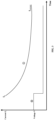
- FIG. 3 exemplarily illustrates the relationship of a start-up current over time in the circuit shown in FIG. 2 under the conventional start-up mode for a DC motor, wherein the horizontal axis represents time, and the vertical axis represents the magnitude of the start-up current Is measured at the positive terminal of the DC motor and the magnitude of the voltage V measured at the negative terminal of the DC motor.
- 1 represents a curve of variation of the start-up current Is of the DC motor 11 over time
- (2) represents a curve of variation of the voltage V over time.
- the circuit where the DC motor is located is rapidly switched from an ON state to an OFF state.
- the voltage V jumps from a high potential to a low potential, and the start-up current I s is at its maximum or peak value I p ; thereafter, the start-up current Is gradually decreases over time until it reaches or approaches a constant current value I constant .
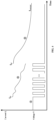
- FIG. 4 exemplarily illustrates the relationship of a start-up current over time in the circuit shown in FIG. 2 under the DC motor start-up mode according to some embodiments, wherein the horizontal axis represents time, and the vertical axis represents the magnitude of the start-up current Is measured at the positive terminal of the DC motor and the magnitude of the voltage V measured at the negative terminal of the DC motor.
- 3 represents a curve of variation of the start-up current Is of the DC motor 11 over time
- (4) represents a curve of variation of the voltage V over time.
- the control signal applied to the gate G is provided in the form of a PWM signal, so that the switching element 110 or the MOS tube T1 periodically switches between an ON state and an OFF state. Accordingly, the voltage V periodically switches between a high potential and a low potential, and the start-up current I s exhibits a peak value I p1 at the start of the time interval T s and gradually decreases in a wave-like manner over time. After the time interval T s ends, the control signal applied to the gate G is kept at a high level, and the switching element maintains the ON state.
- the voltage V is kept at a low level, and the start-up current Is jumps to another peak value I p2 when the switching element begins to maintain the ON state, and gradually decreases over time until it reaches or approaches a constant current value I constant .
- the peak start-up currents I p1 and I p2 in FIG. 4 are smaller than the peak start-up current I p in FIG. 3 . That is, the peak start-up current flowing through the DC motor can be reduced by causing the switching element to periodically switch between an ON state and an OFF state.
- the inventors have found, after in-depth research, that by selecting the frequency of the PWM signal applied to the gate G, the peak start-up currents I p1 and I p2 can be reduced to desired levels.
- the peak start-up currents I p1 and I p2 decrease as the frequency of the PWM signal increases.
- the inventors have also found, after in-depth research, that contrary to intuitive understanding, when the control terminal of the switching element is applied with a PWM signal, the peak start-up current I p1 is not always greater than the peak value I p2 . In other words, merely controlling the peak start-up current I p1 below the desired level does not ensure that the peak value of the start-up current is below the desired level. This implies that in order to reduce the peak start-up current, it is necessary to choose a higher PWM signal frequency, thus facing more challenges in terms of costs and circuit design.
- the inventors Upon further research, the inventors have found that by making the predetermined time interval T s sufficiently large, the peak value I p1 could be greater than the peak value I p2 .
- the start-up current of the DC motor can be reduced through the following means: first, lowering the peak start-up current I p1 to the desired level by selecting the frequency of the PWM signal applied to the gate G; then, ensuring that the peak value I p1 is greater than the peak value I p2 by choosing the predetermined time interval T s .
- the predetermined time interval T s it is possible to circumvent such issues as increased costs and rise in complexity of circuit design resulted from using a higher PWM signal frequency.
- FIG. 5 shows a flow diagram of a method for reducing DC motor start-up current according to some other embodiments. Exemplarily, the method described hereinafter is implemented by means of the start-up device shown in FIG. 1 or FIG. 2 .
- the method illustrated by FIG. 5 includes the following steps:
- the frequency of the PWM signal is set such that the value of the start-up current at the start of the time interval T s is less than a first threshold value TH1.
- the length of the predetermined time interval T s is set to be greater than a second threshold value TH2, so that the value of the start-up current at the start of the predetermined time interval T s (peak value I p1 ) is greater than the value when the switching element begins to maintain the ON state (peak value I p2 ).
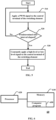
- FIG. 6 shows a schematic block diagram of a typical control device.
- the control device shown in FIG. 6 can be used for implementing the control unit shown in FIGS. 1 and 2 .
- the control device 60 includes a memory 610 (for example, a non-volatile memory such as flash memory, ROM, hard drive, magnetic disk and optical disk), a processor 620, and a computer program 630.
- a memory 610 for example, a non-volatile memory such as flash memory, ROM, hard drive, magnetic disk and optical disk
- a processor 620 for example, a central processing unit (CPU) 620
- a computer program 630 for example, a computer program 630.
- the memory 610 stores the computer program 630.
- the processor 320 is configured to execute the computer program 630 stored on the memory 610 to implement one or more steps included in the method illustrated by FIG. 5 .
- a computer-readable storage medium with a computer program stored thereon (e.g. the computer program 630 in FIG. 6 ).
- the program when executed by a processor (e.g. the processor 620 in FIG. 6 ), can implement the one or more steps in the method illustrated by FIG. 5 .
- the computer-readable storage medium as referred to herein includes various types of computer storage media, which may be any usable medium accessible by a general-purpose or specialized computer.
- the computer-readable storage medium may include RAM, ROM, EPROM, E2PROM, register, hard disk, removable disk, CD-ROM or other optical disk memory, disk memory or other magnetic storage device, or any other temporary or non-temporary medium capable of carrying or storing desired program code units in the form of instructions or data structures and also capable of being accessed by a general-purpose or specific-purpose computer or processor.
- An exemplary storage medium is coupled to a processor to enable the processor to read and write information from/to the storage medium.
- the storage medium may be integrated into the processor.
- the processor and the storage medium may reside in an ASIC.
- the ASIC may reside in a user terminal.
- the processor and the storage medium may reside as separate components within the user terminal.
Landscapes
- Engineering & Computer Science (AREA)
- Power Engineering (AREA)
- Computer Security & Cryptography (AREA)
- Motor And Converter Starters (AREA)
Abstract
The present application relates to a motor control technology, and in particular to a start-up device (10) for a DC motor (12). The start-up device (10) includes: a switching element (110) connected in series within a circuit comprising the DC motor (12) and a DC power supply (11); and a control unit (120) configured to cause the switching element (110) to periodically switch between an ON state and an OFF state in a predetermined time interval (Ts) to reduce the peak value of a start-up current (Ip) flowing through the DC motor (12), and to cause the switching element (110) to maintain the ON state after the predetermined time interval (Ts) ends.
Description
- The present invention relates to a motor control technology, and in particular to a start-up device for a DC motor, a motor system comprising the start-up device, a method for reducing DC motor start-up current, and a computer-readable storage medium with a computer program stored thereon for implementing the method.
- The start-up current of a brushed DC motor commonly has a relatively high peak value, typically multiple times higher than rated current. This necessitates the use of high-standard and high-quality electronic components (e.g. a metal-oxide-semiconductor field-effect transistor (MOSFET), a current sampling resistor, a protecting fuse and a wire gauge etc.), leading to product costs remaining high. In addition, even if the above technical measure has been taken, it is still difficult to avoid component burning during long-term use. Therefore, reducing DC motor start-up current is an urgent problem to be solved.
- According to one aspect of the present invention, there is provided a start-up device for a DC motor, comprising:
- a switching element connected in series within a circuit comprising the DC motor and a DC power supply; and
- a control unit configured to cause the switching element to periodically switch between an ON state and an OFF state in a predetermined time interval to reduce a peak value of a start-up current flowing through the DC motor, and to cause the switching element to maintain the ON state after the predetermined time interval ends.
- Optionally, the above start-up device further comprises an overcurrent protection component coupled between the DC power supply and the DC motor.
- Optionally, the above start-up device further comprises a capacitor connected between positive and negative terminals of the DC motor to absorb electromagnetic pulse components generated by the DC motor.
- Optionally, the switching element is a metal-oxide-semiconductor field-effect transistor (MOSFET) with its gate coupled to the control unit, one of its source and drain coupled to the positive or negative terminal of the DC motor, and the other coupled to ground.
- Optionally, in the start-up device, the control unit causes the switching element to periodically switch between the ON state and the OFF state by applying a pulse width modulation (PWM) signal to the gate.
- Optionally, in the start-up device, a frequency of the pulse width modulation (PWM) signal is set such that a value of the start-up current at the start of the predetermined time interval is smaller than a first threshold value.
- Optionally, in the start-up device, a length of the predetermined time interval is set to be greater than a second threshold value, so that the value of the start-up current at the start of the predetermined time interval is greater than a value when the switching element begins to maintain the ON state.
- According to another aspect of the present invention, there is provided a motor system, comprising:
- a DC motor, comprising positive and negative terminals; and
- a start-up device, comprising:
- a switching element connected in series within a circuit comprising the DC motor and a DC power supply; and
- a control unit configured to cause the switching element to periodically switch between an ON state and an OFF state in a predetermined time interval to reduce a peak value of a start-up current flowing through the DC motor, and to cause the switching element to maintain the ON state after the predetermined time interval ends.
- According to yet another aspect of the present invention, there is provided a method for reducing DC motor start-up current, comprising:
- causing a switching element connected in series within a circuit comprising the DC motor and a DC power supply to periodically switch between an ON state and an OFF state in a predetermined time interval to reduce a peak value of a start-up current flowing through the DC motor; and
- causing the switching element to maintain the ON state after the predetermined time interval ends.
- According to still another aspect of the present invention, there is provided a computer-readable storage medium, with a computer program stored thereon suitable for execution on a processor of a terminal device, the execution of the computer program enabling the steps of the method as described above to be performed.
- The above and/or other aspects and advantages of the present invention will become clearer and easier to understand in conjunction with the following description in various aspects of the drawings, which are provided by way of example only. The same or similar units in the drawings are represented by the same reference numerals. The drawings include:
-
FIG. 1 shows a schematic block diagram of a start-up device for a DC motor. -
FIG. 2 shows a schematic circuit diagram of a start-up device for another DC motor. -
FIG. 3 exemplarily illustrates the relationship of a start-up current over time in the circuit shown inFIG. 2 under the conventional start-up mode for a DC motor. -
FIG. 4 exemplarily illustrates the relationship of a start-up current over time in the circuit shown inFIG. 2 under the DC motor start-up mode. -
FIG. 5 shows a flow diagram of a method for reducing DC motor start-up current. -
FIG. 6 shows a schematic block diagram of a typical control device. - The present invention will be more fully described hereinafter with reference to the drawings of the exemplary embodiments of the present invention. However, the present invention may be implemented in different forms, and should not be construed as being limited only by the various embodiments provided herein.
- In this specification, the terms such as "comprise" and "include" indicate that in addition to the units and steps directly and explicitly stated in the specification and claims, the technical solution also does not exclude the circumstances where there are other units and steps that are not directly or explicitly stated.
- In this specification, the terms such as "A and B coupled" and "A coupled to B" denote the following circumstances: i) A and B have a direct electrical or mechanical connection, etc.; ii) A and B are electrically or mechanically connected through C, etc.
- Unless otherwise specified, in this specification, the terms such as "first" and "second" do not indicate the sequence of units in such aspects as time, space, size, etc., but are only used to distinguish between units.
-
FIG. 1 shows a schematic block diagram of a start-up device for a DC motor according to some embodiments. It should be pointed out that, in addition to the units shown inFIG. 1 , the start-up device further includes other units essential for implementing the start-up function. However, for the sake of conciseness, the description ofFIG. 1 only involves units that are directly related to the subject of reducing start-up current. - The start-
up device 10 shown inFIG. 1 includes aswitching element 110 and acontrol unit 120. Referring toFIG. 1 , the positive and negative terminals of aDC motor 11 are coupled to aDC power supply 12 and theswitching element 110, respectively. It is worth mentioning that, in addition to the circumstances as illustrated, theswitching element 110 may also be connected in series in other locations within a circuit L comprising the DC motor and theDC power supply 12. For instance, theswitching element 110 may be located between the positive terminal of theDC motor 11 and theDC power supply 12. - On the other hand, the
control unit 120 is coupled to the control terminal of theswitching element 110 to control the ON-OFF state of theswitching element 110. In some embodiments, thecontrol unit 120 regulates the peak value of the start-up current (hereinafter referred to as the peak start-up current) Ip of theDC motor 11 by controlling the ON-OFF state of theswitching element 110. Specifically, in a predetermined time interval Ts, thecontrol unit 120 may cause theswitching element 110 to periodically switch between an ON state and an OFF state to reduce the peak start-up current Ip flowing through the DC motor. The predetermined time interval Ts described herein corresponds to a start-up phase of theDC motor 11, and thus can be understood as a start-up period of the DC motor. After the start-up period is over, thecontrol unit 120 will cause theswitching element 110 to maintain the ON state. - In some embodiments, the
switching element 110 is implemented using a metal-oxide-semiconductor field-effect transistor (MOSFET) with its gate coupled to thecontrol unit 120, one of the source S and drain D coupled to the positive or negative terminal of theDC motor 11, and the other coupled to ground. -
FIG. 2 shows a schematic circuit diagram of a start-up device for a DC motor according to some other embodiments. - In the circuit 20 illustrated by
FIG. 2 , the switching element is implemented using an NMOS tube T1 with its gate G connected to thecontrol unit 120 via a resistor R1 and grounded via a voltage divider resistor R2, the drain D connected to the negative terminal of theDC motor 11, and the source S grounded via a current sampling resistor R3. It should be noted that, the type of the MOS tube as illustrated herein is merely exemplary, and in some alternative implementations, a PMOS tube may also be used as theswitching element 110. Furthermore, the way of connecting the MOS tube to the DC motor and other units, and the location thereof in the circuit, as illustrated inFIG. 2 , are also only exemplary. Other alternative ways, for example, include, but are not limited to: the source S of the NMOS tube T1 is coupled to the negative terminal of theDC motor 11, and the drain D is grounded via the current sampling resistor R3; or the NMOS tube T1 is coupled between theDC power supply 12 and the positive terminal of theDC motor 11, wherein the source S (drain D) is coupled to theDC power supply 12, and the drain D (source S) is coupled to the positive terminal of theDC motor 11. - Continuing to refer to
FIG. 2 , the circuit 20 further includes an overcurrent protection component F (e.g. a protecting fuse) connected between theDC power supply 12 and the positive terminal of theDC motor 11, and a capacitor C (for absorbing electromagnetic pulse components generated by the DC motor) connected between the positive and negative terminals of theDC motor 11. The circuit 20 still further includes a diode D reversely connected between the positive and negative terminals of theDC motor 11. - In the embodiments illustrated by
FIG. 2 , thecontrol unit 120 may enable the switching element (specifically illustrated by the NMOS tube T1) to periodically switch between an ON state and an OFF state by applying a pulse width modulation (PWM) signal to the gate G. -
FIG. 3 exemplarily illustrates the relationship of a start-up current over time in the circuit shown inFIG. 2 under the conventional start-up mode for a DC motor, wherein the horizontal axis represents time, and the vertical axis represents the magnitude of the start-up current Is measured at the positive terminal of the DC motor and the magnitude of the voltage V measured at the negative terminal of the DC motor. In particular, inFIG. 3 , ① represents a curve of variation of the start-up current Is of theDC motor 11 over time, and (2) represents a curve of variation of the voltage V over time. - When the control signal applied to the gate G jumps from a low level to a high level, the circuit where the DC motor is located is rapidly switched from an ON state to an OFF state. Correspondingly, as illustrated in
FIG. 3 , the voltage V jumps from a high potential to a low potential, and the start-up current Is is at its maximum or peak value Ip; thereafter, the start-up current Is gradually decreases over time until it reaches or approaches a constant current value Iconstant. -
FIG. 4 exemplarily illustrates the relationship of a start-up current over time in the circuit shown inFIG. 2 under the DC motor start-up mode according to some embodiments, wherein the horizontal axis represents time, and the vertical axis represents the magnitude of the start-up current Is measured at the positive terminal of the DC motor and the magnitude of the voltage V measured at the negative terminal of the DC motor. In particular, inFIG. 4 , ③ represents a curve of variation of the start-up current Is of theDC motor 11 over time, and (4) represents a curve of variation of the voltage V over time. - Referring to
FIG. 4 , unlike the start-up mode shown inFIG. 3 , in a predetermined time interval Ts, the control signal applied to the gate G is provided in the form of a PWM signal, so that the switchingelement 110 or the MOS tube T1 periodically switches between an ON state and an OFF state. Accordingly, the voltage V periodically switches between a high potential and a low potential, and the start-up current Is exhibits a peak value Ip1 at the start of the time interval Ts and gradually decreases in a wave-like manner over time. After the time interval Ts ends, the control signal applied to the gate G is kept at a high level, and the switching element maintains the ON state. Correspondingly, the voltage V is kept at a low level, and the start-up current Is jumps to another peak value Ip2 when the switching element begins to maintain the ON state, and gradually decreases over time until it reaches or approaches a constant current value Iconstant. Upon comparison ofFIGS. 3 and4 , it is evident that the peak start-up currents Ip1 and Ip2 inFIG. 4 are smaller than the peak start-up current Ip inFIG. 3 . That is, the peak start-up current flowing through the DC motor can be reduced by causing the switching element to periodically switch between an ON state and an OFF state. - The inventors have found, after in-depth research, that by selecting the frequency of the PWM signal applied to the gate G, the peak start-up currents Ip1 and Ip2 can be reduced to desired levels. In particular, the peak start-up currents Ip1 and Ip2 decrease as the frequency of the PWM signal increases.
- The inventors have also found, after in-depth research, that contrary to intuitive understanding, when the control terminal of the switching element is applied with a PWM signal, the peak start-up current Ip1 is not always greater than the peak value Ip2. In other words, merely controlling the peak start-up current Ip1 below the desired level does not ensure that the peak value of the start-up current is below the desired level. This implies that in order to reduce the peak start-up current, it is necessary to choose a higher PWM signal frequency, thus facing more challenges in terms of costs and circuit design.
- Upon further research, the inventors have found that by making the predetermined time interval Ts sufficiently large, the peak value Ip1 could be greater than the peak value Ip2.
- Based on the above findings, in some embodiments, the start-up current of the DC motor can be reduced through the following means: first, lowering the peak start-up current Ip1 to the desired level by selecting the frequency of the PWM signal applied to the gate G; then, ensuring that the peak value Ip1 is greater than the peak value Ip2 by choosing the predetermined time interval Ts. In this way, it is possible to circumvent such issues as increased costs and rise in complexity of circuit design resulted from using a higher PWM signal frequency.
-
FIG. 5 shows a flow diagram of a method for reducing DC motor start-up current according to some other embodiments. Exemplarily, the method described hereinafter is implemented by means of the start-up device shown inFIG. 1 or FIG. 2 . - The method illustrated by
FIG. 5 includes the following steps: - Step 510: The
control unit 120 causes theswitching element 110 to periodically switch between an ON state and an OFF state, for example, by applying a PWM signal to the control terminal (e.g. the gate G) of theswitching element 110. - Step 520: The
control unit 120 determines whether a predetermined time interval Ts has elapsed since the application of the PWM signal; if the time interval Ts has elapsed, the process proceeds to step 530; otherwise, it returns to step 510. - Step 530: The
control unit 120 causes theswitching element 110 to maintain the ON state, for example, by constantly applying a high-level signal (in the event of the switching element being a NMOS tube) or a low-level signal (in the event of the switching element being a PMOS tube) to the control terminal (e.g. the gate G) of theswitching element 110. - Optionally, the frequency of the PWM signal is set such that the value of the start-up current at the start of the time interval Ts is less than a first threshold value TH1.
- Further optionally, the length of the predetermined time interval Ts is set to be greater than a second threshold value TH2, so that the value of the start-up current at the start of the predetermined time interval Ts (peak value Ip1) is greater than the value when the switching element begins to maintain the ON state (peak value Ip2).
-
FIG. 6 shows a schematic block diagram of a typical control device. The control device shown inFIG. 6 can be used for implementing the control unit shown inFIGS. 1 and 2 . - As illustrated in
FIG. 6 , thecontrol device 60 includes a memory 610 (for example, a non-volatile memory such as flash memory, ROM, hard drive, magnetic disk and optical disk), aprocessor 620, and acomputer program 630. - The
memory 610 stores thecomputer program 630. The processor 320 is configured to execute thecomputer program 630 stored on thememory 610 to implement one or more steps included in the method illustrated byFIG. 5 . - There is also provided a computer-readable storage medium, with a computer program stored thereon (e.g. the
computer program 630 inFIG. 6 ). The program, when executed by a processor (e.g. theprocessor 620 inFIG. 6 ), can implement the one or more steps in the method illustrated byFIG. 5 . - The computer-readable storage medium as referred to herein includes various types of computer storage media, which may be any usable medium accessible by a general-purpose or specialized computer. For example, the computer-readable storage medium may include RAM, ROM, EPROM, E2PROM, register, hard disk, removable disk, CD-ROM or other optical disk memory, disk memory or other magnetic storage device, or any other temporary or non-temporary medium capable of carrying or storing desired program code units in the form of instructions or data structures and also capable of being accessed by a general-purpose or specific-purpose computer or processor. The combination of the above should also be included within the scope of protection of the computer-readable storage medium. An exemplary storage medium is coupled to a processor to enable the processor to read and write information from/to the storage medium. In alternative solutions, the storage medium may be integrated into the processor. The processor and the storage medium may reside in an ASIC. The ASIC may reside in a user terminal. In alternative solutions, the processor and the storage medium may reside as separate components within the user terminal.
- A person skilled in the art will appreciate that, various illustrative logic blocks, modules, circuits and algorithmic steps described herein may be implemented as electronic hardware, computer hardware or a combination of both.
- To demonstrate interchangeability between hardware and software, various illustrative components, blocks, modules, circuits and steps have been described above in general terms based on their functionality. Such functionality is implemented in the form of hardware or software, depending on particular applications and design constraints imposed on the overall system. A person skilled in the art may implement the described functionality in varying ways for particular applications, but such implementation decisions should not be construed to result in a departure from the scope of the present invention.
- While only some embodiments of the present invention are described, it should be understood by a person skilled in the art that the present invention can be implemented in various other forms without departing from the scope of the present invention as defined by the appended claims. Therefore, the examples and embodiments provided are intended to be illustrative rather than restrictive, and the present invention may encompass various modifications and substitutions without departing from the scope of the present invention as defined in the appended claims.
- The embodiments and examples are provided herein to explain the embodiments of the technology and its particular application, so that a person skilled in the art can exploit and implement the present invention. However, a person skilled in the art will appreciate that the foregoing description and examples are provided for the purpose of illustration and exemplification only. The description provided is not intended to cover every aspect of the present invention or to limit the present invention to the precise form disclosed.
- The following clauses set out aspects of the present invention which may or may not presently be claimed, but which may provide basis for future amendment and/or a divisional application.
- 1. A start-up device for a DC motor, comprising: a switching element connected in series within a circuit comprising the DC motor and a DC power supply; and a control unit configured to cause the switching element to periodically switch between an ON state and an OFF state in a predetermined time interval to reduce a peak value of a start-up current flowing through the DC motor, and to cause the switching element to maintain the ON state after the predetermined time interval ends.
- 2. The start-up device according to
clause 1, further comprising an overcurrent protection component coupled between the DC power supply and the DC motor. - 3. The start-up device according to
clause 1, further comprising a capacitor connected between positive and negative terminals of the DC motor to absorb electromagnetic pulse components generated by the DC motor. - 4. The start-up device according to any one of
clauses 1 to 3, wherein the switching element is a metal-oxide-semiconductor field-effect transistor with a gate thereof coupled to the control unit, one of a source and a drain thereof coupled to the positive or negative terminal of the DC motor, and the other coupled to ground. - 5. The start-up device according to
clause 4, wherein the control unit causes the switching element to periodically switch between the ON state and the OFF state by applying a pulse width modulation signal to the gate. - 6. The start-up device according to clause 5, wherein a frequency of the pulse width modulation signal is set such that a value of the start-up current at the start of the predetermined time interval is smaller than a first threshold value.
- 7. The start-up device according to clause 6, wherein a length of the predetermined time interval is set to be greater than a second threshold value, so that the value of the start-up current at the start of the predetermined time interval is greater than a value when the switching element begins to maintain the ON state.
- 8. A motor system, comprising: a DC motor, comprising positive and negative terminals; and a start-up device, comprising: a switching element connected in series within a circuit comprising the DC motor and a DC power supply; and a control unit configured to cause the switching element to periodically switch between an ON state and an OFF state in a predetermined time interval to reduce a peak value of a start-up current flowing through the DC motor, and to cause the switching element to maintain the ON state after the predetermined time interval ends.
- 9. The motor system according to clause 8, wherein the start-up device further comprises an overcurrent protection component coupled between the DC power supply and the DC motor.
- 10. The motor system according to clause 8, wherein the start-up device further comprises a capacitor connected between the positive and negative terminals of the DC motor to absorb electromagnetic pulse components generated by the DC motor.
- 11. The motor system according to any one of clauses 8 to 10, wherein the switching element is a metal-oxide-semiconductor field-effect transistor with a gate thereof coupled to the control unit, one of a source and a drain thereof coupled to the positive or negative terminal of the DC motor, and the other coupled to ground.
- 12. The motor system according to
clause 11, wherein the control unit causes the switching element to periodically switch between the ON state and the OFF state by applying a pulse width modulation signal to the gate. - 13. The motor system according to
clause 12, wherein a frequency of the pulse width modulation signal is set such that a value of the start-up current at the start of the predetermined time interval is smaller than a first threshold value. - 14. The motor system according to clause 13, wherein a length of the predetermined time interval is set to be greater than a second threshold value, so that the value of the start-up current at the start of the predetermined time interval is greater than a value when the switching element begins to maintain the ON state.
- 15. A method for reducing DC motor start-up current, comprising: causing a switching element connected in series within a circuit comprising the DC motor and a DC power supply to periodically switch between an ON state and an OFF state in a predetermined time interval to reduce a peak value of a start-up current flowing through the DC motor; and causing the switching element to maintain the ON state after the predetermined time interval ends.
- 16. The method according to clause 15, wherein the switching element is implemented using a metal-oxide-semiconductor field-effect transistor.
- 17. The method according to clause 16, wherein the switching element periodically switches between the ON state and the OFF state by applying a pulse width modulation signal to the gate of the metal-oxide-semiconductor field-effect transistor.
- 18. The method according to clause 17, wherein a frequency of the pulse width modulation signal is set such that a value of the start-up current at the start of the predetermined time interval is smaller than a first threshold value.
- 19. The method according to clause 18, wherein a length of the predetermined time interval is set to be greater than a second threshold value, so that the value of the start-up current at the start of the predetermined time interval is greater than a value when the switching element begins to maintain the ON state.
- 20. A computer-readable storage medium, with instructions stored thereon, wherein the instructions, when executed by a processor, enable the processor to perform the method according to any one of clauses 15 to 19.
Claims (14)
- A start-up device (10) for a DC motor, comprising:a switching element (110, T1) for connection in series within a circuit comprising the DC motor (12) and a DC power supply (11); anda control unit (120) configured to cause the switching element to periodically switch between an ON state and an OFF state in a predetermined time interval (Ts) to reduce a peak value of a start-up current (Ip) flowing through the DC motor, and to cause the switching element to maintain the ON state after the predetermined time interval ends.
- A start-up device according to claim 1, further comprising an overcurrent protection component (F) for coupling between the DC power supply and the DC motor.
- A start-up device according to claim 1 or 2, further comprising a capacitor (C) for connection between positive and negative terminals of the DC motor to absorb electromagnetic pulse components generated by the DC motor.
- A start-up device according to any one of claims 1 to 3, wherein the switching element is a metal-oxide-semiconductor field-effect transistor with a gate (G) thereof coupled to the control unit, one of a source (S) and a drain (D) thereof for coupling to the positive or negative terminal of the DC motor, and the other coupled to ground.
- A start-up device according to claim 4, wherein the control unit is configured to cause the switching element to periodically switch between the ON state and the OFF state by applying a pulse width modulation signal to the gate.
- A start-up device according to claim 5, wherein a frequency of the pulse width modulation signal is set such that a value of the start-up current at the start of the predetermined time interval is smaller than a first threshold value (TH1).
- A start-up device according to claim 6, wherein a length of the predetermined time interval is set to be greater than a second threshold value (TH2), so that the value of the start-up current at the start of the predetermined time interval is greater than a value when the switching element begins to maintain the ON state.
- A motor system, comprising:a DC motor (12), comprising positive and negative terminals; anda start-up device according to any preceding claim, wherein the switching element is connected in series within a circuit comprising the DC motor and a DC power supply (11).
- A method for reducing DC motor start-up current, comprising:causing a switching element (110, T1) connected in series within a circuit comprising the DC motor (12) and a DC power supply (11) to periodically switch between an ON state and an OFF state in a predetermined time interval (Ts) to reduce a peak value of a start-up current (Ip) flowing through the DC motor; andcausing the switching element to maintain the ON state after the predetermined time interval ends.
- A method according to claim 9, wherein the switching element is implemented using a metal-oxide-semiconductor field-effect transistor.
- A method according to claim 10, wherein the switching element periodically switches between the ON state and the OFF state by applying a pulse width modulation signal to a gate (G) of the metal-oxide-semiconductor field-effect transistor.
- A method according to claim 11, wherein a frequency of the pulse width modulation signal is set such that a value of the start-up current at the start of the predetermined time interval is smaller than a first threshold value (TH1).
- A method according to claim 12, wherein a length of the predetermined time interval is set to be greater than a second threshold value (TH2), so that the value of the start-up current at the start of the predetermined time interval is greater than a value when the switching element begins to maintain the ON state.
- A computer-readable storage medium, with instructions (630) stored thereon, wherein the instructions, when executed by a processor (620), enable the processor to perform a method according to any one of claims 9 to 13.
Applications Claiming Priority (1)
| Application Number | Priority Date | Filing Date | Title |
|---|---|---|---|
| CN202310841321.3A CN119298726A (en) | 2023-07-10 | 2023-07-10 | Starting device, motor system and method for reducing starting current of DC motor |
Publications (1)
| Publication Number | Publication Date |
|---|---|
| EP4492671A1 true EP4492671A1 (en) | 2025-01-15 |
Family
ID=91898417
Family Applications (1)
| Application Number | Title | Priority Date | Filing Date |
|---|---|---|---|
| EP24187371.0A Pending EP4492671A1 (en) | 2023-07-10 | 2024-07-09 | Start-up device, motor system and method for reducing dc motor start-up current |
Country Status (3)
| Country | Link |
|---|---|
| US (1) | US20250023494A1 (en) |
| EP (1) | EP4492671A1 (en) |
| CN (1) | CN119298726A (en) |
Citations (3)
| Publication number | Priority date | Publication date | Assignee | Title |
|---|---|---|---|---|
| US4851743A (en) * | 1987-10-27 | 1989-07-25 | Eaton Corporation | DC motor speed controller having protection |
| US20050194998A1 (en) * | 2004-03-03 | 2005-09-08 | Denso Corporation | Load-driving device and method of driving load |
| US20070098373A1 (en) * | 2003-12-01 | 2007-05-03 | Koichi Saito | Dc motor drive unit |
Family Cites Families (3)
| Publication number | Priority date | Publication date | Assignee | Title |
|---|---|---|---|---|
| JP5586312B2 (en) * | 2010-04-22 | 2014-09-10 | セミコンダクター・コンポーネンツ・インダストリーズ・リミテッド・ライアビリティ・カンパニー | Motor drive circuit |
| JP7203899B2 (en) * | 2021-06-01 | 2023-01-13 | 三菱電機株式会社 | motor generator controller |
| JP2023047512A (en) * | 2021-09-27 | 2023-04-06 | ローム株式会社 | Motor drive circuits, motor systems, and electrical equipment |
-
2023
- 2023-07-10 CN CN202310841321.3A patent/CN119298726A/en active Pending
-
2024
- 2024-07-02 US US18/761,622 patent/US20250023494A1/en active Pending
- 2024-07-09 EP EP24187371.0A patent/EP4492671A1/en active Pending
Patent Citations (3)
| Publication number | Priority date | Publication date | Assignee | Title |
|---|---|---|---|---|
| US4851743A (en) * | 1987-10-27 | 1989-07-25 | Eaton Corporation | DC motor speed controller having protection |
| US20070098373A1 (en) * | 2003-12-01 | 2007-05-03 | Koichi Saito | Dc motor drive unit |
| US20050194998A1 (en) * | 2004-03-03 | 2005-09-08 | Denso Corporation | Load-driving device and method of driving load |
Also Published As
| Publication number | Publication date |
|---|---|
| CN119298726A (en) | 2025-01-10 |
| US20250023494A1 (en) | 2025-01-16 |
Similar Documents
| Publication | Publication Date | Title |
|---|---|---|
| JP6170119B2 (en) | System and method for driving a power switch | |
| CN107302351B (en) | Driving device and inductive load driving device | |
| CN104660046B (en) | Constant current control circuit of power converter and its constant current control method | |
| CN101820243B (en) | Motor drive circuit | |
| US20040051513A1 (en) | Switching regulator with dynamic current limiting and drive circuit for the switching regulator | |
| TWI845147B (en) | GaN drive circuit | |
| CN106253753B (en) | Semiconductor device with a plurality of semiconductor chips | |
| JP2024068841A (en) | Linear Regulators | |
| WO2021054027A1 (en) | Power supply device | |
| US11757443B2 (en) | Electrical switching systems including constant-power controllers and associated methods | |
| FI108971B (en) | Method and arrangement for limiting the power supply start-up current | |
| US20250023494A1 (en) | Start-up device, motor system and method for reducing dc motor start-up current | |
| US10622991B2 (en) | Switch driver | |
| JP7568502B2 (en) | Switching power supply circuit and switching power supply device | |
| TW200428775A (en) | Method and apparatus for determining the switching state of a transistor | |
| JP2024000017A (en) | Switching power supply circuit and switching power supply device | |
| CN108711918A (en) | A kind of switched charge circuit | |
| JP2006288054A (en) | Soft start circuit | |
| CN214674319U (en) | Voltage spike suppression circuit and battery protection circuit | |
| JP2020120546A (en) | Electric power unit | |
| US10754366B2 (en) | Power switching circuits having a saturable inductor | |
| CN208754024U (en) | A kind of switched charge circuit | |
| CN223462731U (en) | Overcurrent protection circuit and electrical equipment | |
| US20090237849A1 (en) | Apparatus for preventing surge | |
| CN215956266U (en) | DC power supply slow starting circuit with current limiting function |
Legal Events
| Date | Code | Title | Description |
|---|---|---|---|
| PUAI | Public reference made under article 153(3) epc to a published international application that has entered the european phase |
Free format text: ORIGINAL CODE: 0009012 |
|
| STAA | Information on the status of an ep patent application or granted ep patent |
Free format text: STATUS: THE APPLICATION HAS BEEN PUBLISHED |
|
| AK | Designated contracting states |
Kind code of ref document: A1 Designated state(s): AL AT BE BG CH CY CZ DE DK EE ES FI FR GB GR HR HU IE IS IT LI LT LU LV MC ME MK MT NL NO PL PT RO RS SE SI SK SM TR |
|
| STAA | Information on the status of an ep patent application or granted ep patent |
Free format text: STATUS: REQUEST FOR EXAMINATION WAS MADE |
|
| 17P | Request for examination filed |
Effective date: 20250617 |