EP4492628A1 - Battery management system, and battery management method - Google Patents
Battery management system, and battery management method Download PDFInfo
- Publication number
- EP4492628A1 EP4492628A1 EP22930912.5A EP22930912A EP4492628A1 EP 4492628 A1 EP4492628 A1 EP 4492628A1 EP 22930912 A EP22930912 A EP 22930912A EP 4492628 A1 EP4492628 A1 EP 4492628A1
- Authority
- EP
- European Patent Office
- Prior art keywords
- capacity
- area
- capacity change
- user
- section
- Prior art date
- Legal status (The legal status is an assumption and is not a legal conclusion. Google has not performed a legal analysis and makes no representation as to the accuracy of the status listed.)
- Pending
Links
Images


Classifications
-
- B—PERFORMING OPERATIONS; TRANSPORTING
- B60—VEHICLES IN GENERAL
- B60L—PROPULSION OF ELECTRICALLY-PROPELLED VEHICLES; SUPPLYING ELECTRIC POWER FOR AUXILIARY EQUIPMENT OF ELECTRICALLY-PROPELLED VEHICLES; ELECTRODYNAMIC BRAKE SYSTEMS FOR VEHICLES IN GENERAL; MAGNETIC SUSPENSION OR LEVITATION FOR VEHICLES; MONITORING OPERATING VARIABLES OF ELECTRICALLY-PROPELLED VEHICLES; ELECTRIC SAFETY DEVICES FOR ELECTRICALLY-PROPELLED VEHICLES
- B60L58/00—Methods or circuit arrangements for monitoring or controlling batteries or fuel cells, specially adapted for electric vehicles
- B60L58/10—Methods or circuit arrangements for monitoring or controlling batteries or fuel cells, specially adapted for electric vehicles for monitoring or controlling batteries
- B60L58/12—Methods or circuit arrangements for monitoring or controlling batteries or fuel cells, specially adapted for electric vehicles for monitoring or controlling batteries responding to state of charge [SoC]
-
- H—ELECTRICITY
- H02—GENERATION; CONVERSION OR DISTRIBUTION OF ELECTRIC POWER
- H02J—ELECTRIC POWER NETWORKS; CIRCUIT ARRANGEMENTS OR SYSTEMS FOR SUPPLYING OR DISTRIBUTING ELECTRIC POWER; SYSTEMS FOR STORING ELECTRIC ENERGY
- H02J7/00—Circuit arrangements for charging or discharging batteries or for supplying loads from batteries
- H02J7/855—Circuit arrangements for charging or discharging batteries or for supplying loads from batteries with circuits adapted for supplying loads from the battery
-
- B—PERFORMING OPERATIONS; TRANSPORTING
- B60—VEHICLES IN GENERAL
- B60L—PROPULSION OF ELECTRICALLY-PROPELLED VEHICLES; SUPPLYING ELECTRIC POWER FOR AUXILIARY EQUIPMENT OF ELECTRICALLY-PROPELLED VEHICLES; ELECTRODYNAMIC BRAKE SYSTEMS FOR VEHICLES IN GENERAL; MAGNETIC SUSPENSION OR LEVITATION FOR VEHICLES; MONITORING OPERATING VARIABLES OF ELECTRICALLY-PROPELLED VEHICLES; ELECTRIC SAFETY DEVICES FOR ELECTRICALLY-PROPELLED VEHICLES
- B60L55/00—Arrangements for supplying energy stored within a vehicle to a power network, i.e. vehicle-to-grid [V2G] arrangements
-
- G—PHYSICS
- G06—COMPUTING OR CALCULATING; COUNTING
- G06Q—INFORMATION AND COMMUNICATION TECHNOLOGY [ICT] SPECIALLY ADAPTED FOR ADMINISTRATIVE, COMMERCIAL, FINANCIAL, MANAGERIAL OR SUPERVISORY PURPOSES; SYSTEMS OR METHODS SPECIALLY ADAPTED FOR ADMINISTRATIVE, COMMERCIAL, FINANCIAL, MANAGERIAL OR SUPERVISORY PURPOSES, NOT OTHERWISE PROVIDED FOR
- G06Q10/00—Administration; Management
- G06Q10/04—Forecasting or optimisation specially adapted for administrative or management purposes, e.g. linear programming or "cutting stock problem"
-
- G—PHYSICS
- G06—COMPUTING OR CALCULATING; COUNTING
- G06Q—INFORMATION AND COMMUNICATION TECHNOLOGY [ICT] SPECIALLY ADAPTED FOR ADMINISTRATIVE, COMMERCIAL, FINANCIAL, MANAGERIAL OR SUPERVISORY PURPOSES; SYSTEMS OR METHODS SPECIALLY ADAPTED FOR ADMINISTRATIVE, COMMERCIAL, FINANCIAL, MANAGERIAL OR SUPERVISORY PURPOSES, NOT OTHERWISE PROVIDED FOR
- G06Q10/00—Administration; Management
- G06Q10/06—Resources, workflows, human or project management; Enterprise or organisation planning; Enterprise or organisation modelling
- G06Q10/063—Operations research, analysis or management
-
- G—PHYSICS
- G06—COMPUTING OR CALCULATING; COUNTING
- G06Q—INFORMATION AND COMMUNICATION TECHNOLOGY [ICT] SPECIALLY ADAPTED FOR ADMINISTRATIVE, COMMERCIAL, FINANCIAL, MANAGERIAL OR SUPERVISORY PURPOSES; SYSTEMS OR METHODS SPECIALLY ADAPTED FOR ADMINISTRATIVE, COMMERCIAL, FINANCIAL, MANAGERIAL OR SUPERVISORY PURPOSES, NOT OTHERWISE PROVIDED FOR
- G06Q50/00—Information and communication technology [ICT] specially adapted for implementation of business processes of specific business sectors, e.g. utilities or tourism
- G06Q50/06—Energy or water supply
-
- G—PHYSICS
- G06—COMPUTING OR CALCULATING; COUNTING
- G06Q—INFORMATION AND COMMUNICATION TECHNOLOGY [ICT] SPECIALLY ADAPTED FOR ADMINISTRATIVE, COMMERCIAL, FINANCIAL, MANAGERIAL OR SUPERVISORY PURPOSES; SYSTEMS OR METHODS SPECIALLY ADAPTED FOR ADMINISTRATIVE, COMMERCIAL, FINANCIAL, MANAGERIAL OR SUPERVISORY PURPOSES, NOT OTHERWISE PROVIDED FOR
- G06Q50/00—Information and communication technology [ICT] specially adapted for implementation of business processes of specific business sectors, e.g. utilities or tourism
- G06Q50/40—Business processes related to the transportation industry
-
- H—ELECTRICITY
- H02—GENERATION; CONVERSION OR DISTRIBUTION OF ELECTRIC POWER
- H02J—ELECTRIC POWER NETWORKS; CIRCUIT ARRANGEMENTS OR SYSTEMS FOR SUPPLYING OR DISTRIBUTING ELECTRIC POWER; SYSTEMS FOR STORING ELECTRIC ENERGY
- H02J3/00—Circuit arrangements for AC mains or AC distribution networks
- H02J3/28—Arrangements for balancing of the load in networks by storage of energy
- H02J3/32—Arrangements for balancing of the load in networks by storage of energy using batteries or super capacitors with converting means
- H02J3/322—Arrangements for balancing of the load in networks by storage of energy using batteries or super capacitors with converting means the battery being on-board an electric or hybrid vehicle, e.g. vehicle to grid arrangements [V2G], power aggregation, use of the battery for network load balancing, coordinated or cooperative battery charging
-
- H—ELECTRICITY
- H02—GENERATION; CONVERSION OR DISTRIBUTION OF ELECTRIC POWER
- H02J—ELECTRIC POWER NETWORKS; CIRCUIT ARRANGEMENTS OR SYSTEMS FOR SUPPLYING OR DISTRIBUTING ELECTRIC POWER; SYSTEMS FOR STORING ELECTRIC ENERGY
- H02J7/00—Circuit arrangements for charging or discharging batteries or for supplying loads from batteries
- H02J7/02—Circuit arrangements for charging or discharging batteries or for supplying loads from batteries for charging batteries from AC mains by converters
-
- H—ELECTRICITY
- H02—GENERATION; CONVERSION OR DISTRIBUTION OF ELECTRIC POWER
- H02J—ELECTRIC POWER NETWORKS; CIRCUIT ARRANGEMENTS OR SYSTEMS FOR SUPPLYING OR DISTRIBUTING ELECTRIC POWER; SYSTEMS FOR STORING ELECTRIC ENERGY
- H02J7/00—Circuit arrangements for charging or discharging batteries or for supplying loads from batteries
- H02J7/80—Circuit arrangements for charging or discharging batteries or for supplying loads from batteries including monitoring or indicating arrangements
-
- H—ELECTRICITY
- H02—GENERATION; CONVERSION OR DISTRIBUTION OF ELECTRIC POWER
- H02J—ELECTRIC POWER NETWORKS; CIRCUIT ARRANGEMENTS OR SYSTEMS FOR SUPPLYING OR DISTRIBUTING ELECTRIC POWER; SYSTEMS FOR STORING ELECTRIC ENERGY
- H02J7/00—Circuit arrangements for charging or discharging batteries or for supplying loads from batteries
- H02J7/90—Regulation of charging or discharging current or voltage
- H02J7/92—Regulation of charging or discharging current or voltage with prioritisation of loads or sources
-
- B—PERFORMING OPERATIONS; TRANSPORTING
- B60—VEHICLES IN GENERAL
- B60L—PROPULSION OF ELECTRICALLY-PROPELLED VEHICLES; SUPPLYING ELECTRIC POWER FOR AUXILIARY EQUIPMENT OF ELECTRICALLY-PROPELLED VEHICLES; ELECTRODYNAMIC BRAKE SYSTEMS FOR VEHICLES IN GENERAL; MAGNETIC SUSPENSION OR LEVITATION FOR VEHICLES; MONITORING OPERATING VARIABLES OF ELECTRICALLY-PROPELLED VEHICLES; ELECTRIC SAFETY DEVICES FOR ELECTRICALLY-PROPELLED VEHICLES
- B60L2240/00—Control parameters of input or output; Target parameters
- B60L2240/60—Navigation input
- B60L2240/66—Ambient conditions
- B60L2240/662—Temperature
-
- B—PERFORMING OPERATIONS; TRANSPORTING
- B60—VEHICLES IN GENERAL
- B60L—PROPULSION OF ELECTRICALLY-PROPELLED VEHICLES; SUPPLYING ELECTRIC POWER FOR AUXILIARY EQUIPMENT OF ELECTRICALLY-PROPELLED VEHICLES; ELECTRODYNAMIC BRAKE SYSTEMS FOR VEHICLES IN GENERAL; MAGNETIC SUSPENSION OR LEVITATION FOR VEHICLES; MONITORING OPERATING VARIABLES OF ELECTRICALLY-PROPELLED VEHICLES; ELECTRIC SAFETY DEVICES FOR ELECTRICALLY-PROPELLED VEHICLES
- B60L2250/00—Driver interactions
- B60L2250/16—Driver interactions by display
-
- B—PERFORMING OPERATIONS; TRANSPORTING
- B60—VEHICLES IN GENERAL
- B60L—PROPULSION OF ELECTRICALLY-PROPELLED VEHICLES; SUPPLYING ELECTRIC POWER FOR AUXILIARY EQUIPMENT OF ELECTRICALLY-PROPELLED VEHICLES; ELECTRODYNAMIC BRAKE SYSTEMS FOR VEHICLES IN GENERAL; MAGNETIC SUSPENSION OR LEVITATION FOR VEHICLES; MONITORING OPERATING VARIABLES OF ELECTRICALLY-PROPELLED VEHICLES; ELECTRIC SAFETY DEVICES FOR ELECTRICALLY-PROPELLED VEHICLES
- B60L2260/00—Operating Modes
- B60L2260/40—Control modes
- B60L2260/50—Control modes by future state prediction
- B60L2260/52—Control modes by future state prediction drive range estimation, e.g. of estimation of available travel distance
-
- B—PERFORMING OPERATIONS; TRANSPORTING
- B60—VEHICLES IN GENERAL
- B60L—PROPULSION OF ELECTRICALLY-PROPELLED VEHICLES; SUPPLYING ELECTRIC POWER FOR AUXILIARY EQUIPMENT OF ELECTRICALLY-PROPELLED VEHICLES; ELECTRODYNAMIC BRAKE SYSTEMS FOR VEHICLES IN GENERAL; MAGNETIC SUSPENSION OR LEVITATION FOR VEHICLES; MONITORING OPERATING VARIABLES OF ELECTRICALLY-PROPELLED VEHICLES; ELECTRIC SAFETY DEVICES FOR ELECTRICALLY-PROPELLED VEHICLES
- B60L2260/00—Operating Modes
- B60L2260/40—Control modes
- B60L2260/50—Control modes by future state prediction
- B60L2260/54—Energy consumption estimation
-
- H—ELECTRICITY
- H02—GENERATION; CONVERSION OR DISTRIBUTION OF ELECTRIC POWER
- H02J—ELECTRIC POWER NETWORKS; CIRCUIT ARRANGEMENTS OR SYSTEMS FOR SUPPLYING OR DISTRIBUTING ELECTRIC POWER; SYSTEMS FOR STORING ELECTRIC ENERGY
- H02J2105/00—Networks for supplying or distributing electric power characterised by their spatial reach or by the load
- H02J2105/30—Networks for supplying or distributing electric power characterised by their spatial reach or by the load the load networks being external to vehicles, i.e. exchanging power with vehicles
- H02J2105/33—Networks for supplying or distributing electric power characterised by their spatial reach or by the load the load networks being external to vehicles, i.e. exchanging power with vehicles exchanging power with road vehicles
- H02J2105/37—Networks for supplying or distributing electric power characterised by their spatial reach or by the load the load networks being external to vehicles, i.e. exchanging power with vehicles exchanging power with road vehicles exchanging power with electric vehicles [EV] or with hybrid electric vehicles [HEV]
-
- H—ELECTRICITY
- H02—GENERATION; CONVERSION OR DISTRIBUTION OF ELECTRIC POWER
- H02J—ELECTRIC POWER NETWORKS; CIRCUIT ARRANGEMENTS OR SYSTEMS FOR SUPPLYING OR DISTRIBUTING ELECTRIC POWER; SYSTEMS FOR STORING ELECTRIC ENERGY
- H02J3/00—Circuit arrangements for AC mains or AC distribution networks
- H02J3/003—Load forecast, e.g. methods or systems for forecasting future load demand
-
- H—ELECTRICITY
- H02—GENERATION; CONVERSION OR DISTRIBUTION OF ELECTRIC POWER
- H02J—ELECTRIC POWER NETWORKS; CIRCUIT ARRANGEMENTS OR SYSTEMS FOR SUPPLYING OR DISTRIBUTING ELECTRIC POWER; SYSTEMS FOR STORING ELECTRIC ENERGY
- H02J3/00—Circuit arrangements for AC mains or AC distribution networks
- H02J3/17—Demand-responsive operation of AC power transmission or distribution networks
-
- Y—GENERAL TAGGING OF NEW TECHNOLOGICAL DEVELOPMENTS; GENERAL TAGGING OF CROSS-SECTIONAL TECHNOLOGIES SPANNING OVER SEVERAL SECTIONS OF THE IPC; TECHNICAL SUBJECTS COVERED BY FORMER USPC CROSS-REFERENCE ART COLLECTIONS [XRACs] AND DIGESTS
- Y02—TECHNOLOGIES OR APPLICATIONS FOR MITIGATION OR ADAPTATION AGAINST CLIMATE CHANGE
- Y02T—CLIMATE CHANGE MITIGATION TECHNOLOGIES RELATED TO TRANSPORTATION
- Y02T10/00—Road transport of goods or passengers
- Y02T10/60—Other road transportation technologies with climate change mitigation effect
- Y02T10/70—Energy storage systems for electromobility, e.g. batteries
Definitions
- the present invention relates to a battery management system, and a battery management method.
- Patent Literature 1 International Publication No. WO 2020/148850
- the conventional technology described above does not mention changing a battery capacity dividing ratio between the vehicle user and the electricity facility, and there has been scope for improvement to make more effective use of a battery mounted on a mobile object such as a vehicle.
- the present invention has been made in view of such background, and an object thereof is to provide a battery management system and a battery management method that can support more effective use of a battery mounted on a mobile object.
- a first aspect to achieve the object is a battery management system including: a battery capacity division section that makes a battery mounted on a mobile object available to each user within an area allocated to the user, by virtually dividing a capacity of the battery into a predetermined number of areas, and individually allocating the areas to the predetermined number of users; a capacity change reception section that receives a capacity change request for requesting a change in a capacity of a first area, the first area being the area allocated to a first user that is any one user among the predetermined number of users; a capacity change adjustment section that, when the capacity change request is received by the capacity change reception section, determines whether or not a capacity of a second area can be changed according to the capacity change request, the second area being the area allocated to a second user other than the first user among the predetermined number of users; and an area capacity change section that, when the capacity change adjustment section determines that the capacity of the second area can be changed according to the capacity change request, changes the capacities of the first area and the second area according to the capacity change request.
- the battery management system may be configured such that when the capacity change request satisfies a condition for acceptance, preset by the second user, of a change in the capacity of the second area, the capacity change adjustment section determines that the capacity of the second area can be changed according to the capacity change request.
- the battery management system may be configured such that, a condition that when a matter requested by the capacity change request is an increase in the capacity of the first area, the first user provides the second user with a predetermined consideration in exchange for a decrease in the capacity of the second area according to the capacity change request is set as the condition for acceptance.
- the battery management system may be configured such that, a condition that a matter requested by the capacity change request is a change in the capacity of the first area that is limited to a predetermined period or less is set as the condition for acceptance.
- the battery management system may be configured to include: an outside temperature recognition section that recognizes an outside temperature around the mobile object; an electricity consumption amount prediction section that predicts an amount of electricity consumption by equipment mounted on the mobile object, based on the outside temperature recognized by the outside temperature recognition section; and a capacity change application section that, when an amount of variation in the amount of electricity consumption predicted by the electricity consumption amount prediction section is a predetermined value or more, applies for the capacity change request to the capacity change reception section.
- the first user may be a user of the mobile object
- the battery management system may be configured to include a capacity change display section that, when the capacity of the first area is changed by the area capacity change section, displays information indicating that the capacity of the first area is changed by using a first display unit displaying a state of charge of the first area, which is included in the mobile object, or a second display unit of a communication terminal used by the first user.
- a second aspect to achieve the object is a battery management method that is executed by a computer, the battery management method including: a battery capacity division step of making a battery mounted in a mobile object available to each user within an area allocated to the user, by virtually dividing a capacity of the battery into a predetermined number of areas, and by individually allocating the areas to the predetermined number of users; a capacity change reception step of receiving a capacity change request for requesting a change in the capacity of a first area, the first area being the area allocated to a first user that is any one user among the predetermined number of users; a capacity change adjustment step of, when the capacity change request is received in the capacity change reception step, determining whether or not a capacity of a second area can be changed according to the capacity change request, the second area being the area allocated to a second user other than the first user among the predetermined number of users; and an area capacity change step of, when the capacity change adjustment step determines that the capacity of the second area can be changed according to the capacity change request, changing the capacities of the first area and
- the battery management system it is possible to support more effective use of a battery mounted on a mobile object.
- the battery management system 1 virtually divides a capacity Ca of the battery 62 mounted on the vehicle 60 into a first area C1 and a second area C2 as shown at callout 65, and allocates the first area C1 to a vehicle user U1 and the second area C2 to an electricity provider U2.
- the battery management system 1 makes the battery 62 available to the vehicle user U1 within the first area C1, makes the battery 62 available to the electricity provider U2 within the second area C2, and thereby supporting more effective use of the battery 62.
- the vehicle 60 corresponds to a mobile object in the present disclosure
- the vehicle user U1 corresponds to a first user in the present disclosure
- the electricity provider U2 corresponds to a second user in the present disclosure.
- the capacity of the battery 62 may be divided into three or more areas to be allocated to three or more users.
- the vehicle 60 is an electric vehicle (battery electric vehicle, plug-in hybrid electric vehicle, or the like) that uses the battery 62 for a drive source, and is connected to charge-discharge equipment 51 attached to property 50, such as a home of the vehicle user U1, through a charge-discharge cable 52.
- the battery 62 is charged with electricity supplied from the charge-discharge equipment 51, and supplies electricity to the charge-discharge equipment 51, via the charge-discharge cable 52.
- the charge-discharge equipment 51 is connected to a plurality of electricity generation facilities 200 operated by the electricity provider U2 via an electricity grid 100, and generated electricity is supplied from the electricity generation facilities 200 to the electricity grid 100.
- the battery 62 is charged with surplus generated electricity via the charge-discharge equipment 51, and when generated electricity to the electricity grid 100 is in short supply, discharged electricity from the battery 62 is supplied to the electricity grid 100.
- Each electricity generation facility 200 generates electricity by using a solar panel 201.
- the battery management system 1 performs communication, via a communication network 300, with a vehicle control device 61, the charge-discharge equipment 51, a communication terminal 70 used by the vehicle user U1, a management system 210 of the electricity provider U2, a weather information server 310, and the like.
- the communication terminal 70 is a smartphone, a mobile phone, a tablet terminal, a notebook personal computer, a desktop personal computer, on-vehicle communication equipment including a car navigation system, or the like.
- the battery management system 1 transmits, to the vehicle control device 61, ratio instruction information Dvr for instructing a ratio setting of the first area C1 to the second area C2 in the battery 62 be set (setting of a capacity of each area). Based on the ratio instruction information Dvr, the vehicle control device 61 performs control of the capacity in the battery 62 in such a manner as to allocate the first area C1 for use by the vehicle user U1 (for discharge or regenerative charge accompanying electricity consumption by the vehicle 60, and charge from the charge-discharge equipment 51 based on an operation by the vehicle user U1), and allocate the second area C2 for use by the electricity provider U2 (for charge as a buffer against electricity generated by the electricity generation facilities 200, and discharge accompanying electricity supply to the electricity grid 100) .
- ratio instruction information Dvr for instructing a ratio setting of the first area C1 to the second area C2 in the battery 62 be set (setting of a capacity of each area).
- the vehicle control device 61 Based on the ratio instruction information Dvr,
- the battery management system 1 performs a process of changing the capacities of the first area C1 and the second area C2 in the battery 62, based on a request from the vehicle user U1, a request from the electricity provider U2, or an external factor such as an outside temperature around the vehicle 60 provided from the weather information server 310. For example, upon receiving capacity change request information Ccr that is transmitted from the communication terminal 70 of the vehicle user U1 and that requests an increase in the capacity of the first area C1, the battery management system 1 determines whether or not a condition for acceptance based on acceptance condition information Awc transmitted from the management system 210 of the electricity provider U2 is satisfied.
- the battery management system 1 changes the capacities of the first area C1 and the second area C2 according to the capacity change request, and transmits, to the vehicle control device 61, ratio instruction information Dvr instructing that the capacities be changed.
- the vehicle control device 61 having received the ratio instruction information Dvr reflects the changes in capacity of the first area C1 and the second area C2 in charge-discharge control of the battery 62, and, on a display unit 63, makes a display indicating that the capacity of the first area C1 has increased.
- the battery management system 1 performs similar adjustment processes for a plurality of vehicle users and a plurality of electricity providers, with regard to divisional use of batteries mounted on a plurality of vehicles.
- the battery management system 1 is a computer system including a processor 10, a memory 30, a communication unit 40, and the like.
- the communication unit 40 performs communication, via the communication network 300, with the vehicle control device 61, the communication terminal 70 used by the vehicle user U1, the management system 210 of the electricity provider U2, the weather information server 310, and the like.
- the memory 30 stores a control program 31 for the battery management system 1, dividing ratio data 32 indicating setting of a dividing ratio of the first area C1 to the second area C2 in the battery 62 (a setting of a capacity of each area), and acceptance condition data 33 indicating a condition for acceptance of a change in the capacity of the second area C2.
- the condition for acceptance is presented by the electricity provider U2.
- the processor 10 reads and executes the control program 31 to function as a battery capacity division section 11, a capacity change reception section 12, a capacity change adjustment section 13, an area capacity change section 14, an outside temperature recognition section 15, an electricity consumption amount prediction section 16, a capacity change application section 17, and a capacity change display section 18.
- a process executed by the battery capacity division section 11 corresponds to a battery capacity division step of a battery management method in the present disclosure
- a process executed by the capacity change reception section 12 corresponds to a capacity change reception step of the battery management method in the present disclosure
- a process executed by the capacity change adjustment section 13 corresponds to a capacity change adjustment step of the battery management method in the present disclosure
- a process executed by the area capacity change section 14 corresponds to an area capacity change step of the battery management method in the present disclosure.
- the battery capacity division section 11 virtually divides, as described above, the capacity Ca of the battery 62 mounted on the vehicle 60 into the first area C1 allocated to the vehicle user U1, and the second area C2 allocated to the electricity provider U2, and stores the dividing ratio data 32 indicating a dividing ratio in the memory 30.
- the battery capacity division section 11 transmits, to the vehicle control device 61, ratio instruction information Dvr instructing that the battery 62 divided into the first area C1 and the second area C2 be used.
- the capacity change reception section 12 receives capacity change request information Ccr transmitted from the communication terminal 70 used by the vehicle user U1 and thus receives a capacity change request of the vehicle user U1 with regard to the first area C1.
- the capacity change adjustment section 13 receives acceptance condition information Awc transmitted from the management system 210 of the electricity provider U2, and recognizes a condition for acceptance of a change in the capacity of the second area C2, which is set by the electricity provider U2.
- condition for acceptance for example, a first condition for acceptance and a second condition for acceptance as follows are set.
- a predetermined consideration in exchange for a decrease in the capacity of the second area C2 is provided from the vehicle user U1 to the electricity provider U2.
- a period for which the capacity of the second area C2 is decreased is limited to a predetermined period (several days or the like) or less.
- the capacity change adjustment section 13 stores the acceptance condition data 33 indicating the conditions for acceptance in the memory 30.
- the capacity change adjustment section 13 determines whether or not the capacity of the second area C2 can be changed according to the capacity change request. Specifically, when the capacity change request satisfies the first condition for acceptance or the second condition for acceptance, the capacity change adjustment section 13 determines that the capacity of the second area C2 can be changed according to the capacity change request.
- the capacity change adjustment section 13 transmits the capacity change request information to the management system 210, and inquires of the electricity provider U2 whether or not the capacity of the second area C2 can be changed according to the capacity change request.
- capacity change approval information approving of a change in the capacity of the second area C2 according to the capacity change request is received from the management system 210, the capacity change adjustment section 13 determines that the capacity of the second area C2 can be changed according to the capacity change request.
- the area capacity change section 14 changes the capacities of the first area C1 and the second area C2 according to the capacity change request.
- the battery capacity division section 11 updates the dividing ratio data 32 to data indicating a dividing ratio of the changed first area C1 to the changed second area C2, and transmits, to the vehicle control device 61, ratio instruction information Dvr instructing that the battery 62 be used according to the changed dividing ratio.
- the outside temperature recognition section 15 recognizes an outside temperature around the vehicle 60, based on weather information on the vicinity of a position where the vehicle 60 is parked, which is provided from the weather information server 310, or verified temperature information obtained by an outside temperature sensor mounted on the vehicle 60, which is transmitted from the vehicle control device 61.
- the electricity consumption amount prediction section 16 predicts power consumption by equipment included in the vehicle 60 (an air-conditioning system, a cooling system for temperature management of the battery 62, or the like), based on the outside temperature around the vehicle 60 recognized by the outside temperature recognition section 15. For example, when the outside temperature is a low temperature that is a predetermined temperature or less, the electricity consumption amount prediction section 16 predicts that electricity consumption will be high for heating by the air-conditioning system.
- the capacity change application section 17 applies for a capacity change request to the capacity change reception section 12.
- the capacity change request requests that the capacity of the first area C1 be changed according to the amount of variation in the amount of electricity consumption.
- the amount of variation in the electricity consumption may be the amount of variation throughout periods in units such as one day or several days, and an application for a capacity change may have a content requesting that, for example, the first area C1 be increased for a period during which the amount of electricity consumption increases, such as for several months in winter.
- A2 shows an example in which for a period during which the amount of electricity generated by the solar panels 201 decreases while power consumption by equipment of the vehicle 60 increases in winter, the capacity of the first area C1 is increased and the capacity of the second area C2 is decreased, from settings for ordinary use in A1.
- A3 shows an example in which when the vehicle user U1 goes to a distant place by the vehicle 60, capacity change request information Ccr to increase the capacity of the first area C1 is transmitted from the communication terminal 70 to the battery management system 1, and in response thereto, the capacity of the first area C1 is increased to the entire capacity Ca of the battery 62.
- the capacity change display section 18 transmits, to the vehicle control device 61, display change information instructing that information indicating that the capacity of the first area C1 has been changed by the area capacity change section 14 be displayed.
- the vehicle control device 61 makes a display indicating that the capacity of the first area C1 has been changed, on the display unit 63 included in the vehicle 60.
- Figures 4 and 5 show examples of the display made when the first area C1 has been changed.
- Figure 4 is an example of the display in which the capacity of the first area C1 is displayed, and is changed from X1 kWh shown in A4 to X2 kWh shown in A5.
- Figure 5 is an example of the display in which the size of a display area is changed, and when the capacity of the first area C1 is increased, the size of the display area for the remaining amount of stored electricity is increased from a size shown in A6 to a size shown in A7.
- step S1 when capacity change request information Ccr is received from the communication terminal 70 of the vehicle user U1 in step S1, or when an application for a capacity change is made as a result of the amount of variation in the amount of electricity consumption predicted by the electricity consumption amount prediction section 16 becoming a predetermined value or more in step S10, the capacity change reception section 12 moves the process to step S2.
- step S2 the capacity change adjustment section 13 determines whether or not the content of a capacity change request according to the capacity change request information Ccr or the application for a capacity change satisfies the first condition for acceptance or the second condition for acceptance presented by the electricity provider U2.
- the capacity change adjustment section 13 moves the process to step S20 when the content of the capacity change request satisfies the first condition for acceptance or the second condition for acceptance, and moves the process to step S3 when the content of the capacity change request satisfies neither the first condition for acceptance nor the second condition for acceptance.
- step S3 the capacity change adjustment section 13 transmits the capacity change request information Ccr to the management system 210 of the electricity provider U2 and inquires of the management system 210 of the electricity provider U2 whether or not to approve of a change in the capacity of the second area C2 according to the capacity change request.
- step S4 the capacity change adjustment section 13 moves the process to step S20 when capacity change approval information approving of a change in the capacity of the second area C2 according to the capacity change request is received from the management system 210 of the electricity provider U2.
- the capacity change adjustment section 13 moves the process to step S5, in which capacity change disapproval information notifying that a change in the capacity of the first area C1 according to the capacity change request is disapproved of is transmitted to the communication terminal 70 of the vehicle user U1.
- the notification that a change in the capacity of the first area C1 is disapproved of is displayed on a display unit of the communication terminal 70.
- step S20 the area capacity change section 14 changes the capacities of the first area C1 and the second area C2, based on the capacity change request.
- step S21 the battery capacity division section 11 transmits, to the vehicle control device 61, ratio instruction information Dvr indicating a dividing ratio corresponding to the capacities of the first area C1 and the second area C2 changed by the area capacity change section 14.
- ratio instruction information Dvr indicating a dividing ratio corresponding to the capacities of the first area C1 and the second area C2 changed by the area capacity change section 14.
- the capacity change display section 18 transmits, to the vehicle control device 61, display change information instructing that the display of the remaining amount of stored electricity be changed according to the change in the capacity of the first area C1.
- the vehicle control device 61 having received the display change information changes the displayed aspect of the remaining amount of stored electricity in the first area C1, as described above with reference to Figures 4 and 5 .
- the capacity change display section 18 transmits, to the communication terminal 70 of the vehicle user U1, capacity change execution information notifying that the capacity of the first area C1 has been changed.
- the communication terminal 70 having received the capacity change execution information makes a display notifying that the capacity of the first area C1 has been changed, on the display unit of the communication terminal 70. Thus, it can be notified to the vehicle user U1 that the capacity of the first area C1 has been changed.
- the mobile object in the present disclosure may be any mobile object that includes a battery that is charged and discharged by charge-discharge equipment, and may be an aircraft, a watercraft, or the like.
- a case is described in which a change in the capacity of the second area C2 allocated to the electricity provider U2 is adjusted in response to a capacity change request of the vehicle user U1 with regard to the first area C1.
- a case where a change in the capacity of the first area C1 allocated to the vehicle user U1 is adjusted in response to a capacity change request of the electricity provider U2 with regard to the second area C2 can also be handled through similar processes.
- the electricity provider U2 is a first user in the present disclosure
- the vehicle user U1 is a second user in the present disclosure.
- the outside temperature recognition section 15, the electricity consumption amount prediction section 16, and the capacity change application section 17 are included, and the processes to change the capacity of the first area C1 are performed based on the amount of electricity consumption by equipment included in the vehicle 60.
- a configuration may be made that omits the outside temperature recognition section 15, the electricity consumption amount prediction section 16, and the capacity change application section 17.
- the capacity change display section 18 is included, and when the capacity of the first area C1 is changed, information indicating that the capacity of the first area C1 has been changed is displayed on the display unit 63 of the vehicle 60 or on the display unit of the communication terminal 70.
- a configuration may be made that omits the capacity change display section 18.
- the battery management system 1 in the present disclosure is configured by a computer system that performs communication with the vehicle 60 on which the battery 62 is mounted.
- the battery management system may be configured as a function of the vehicle control device 61. In such a case, a configuration is made such that communication is performed between the vehicle control device 61 and each of the communication terminal 70 of the vehicle user U1 and the management system 210 of the electricity provider U2.
- FIG. 2 is a schematic diagram showing functional structure of the battery management system 1 that is segmented based on main processes, in order to facilitate the understanding of the invention of the present application, and the structure of the battery management system 1 may be configured based on other segments.
- a process by each constituent element may be executed by one hardware unit, or may be executed by a plurality of hardware units.
- the process by each constituent element shown in Figure 6 may be executed by using one program, or may be executed by using a plurality of programs.
- the embodiment is a specific example of following configurations.
- a battery management system including: a battery capacity division section that makes a battery mounted on a mobile object available to each user within an area allocated to the user, by virtually dividing a capacity of the battery into a predetermined number of areas, and individually allocating the areas to the predetermined number of users, ; a capacity change reception section that receives a capacity change request for requesting a change in a capacity of a first area, the first area being the area allocated to a first user that is any one user among the predetermined number of users; a capacity change adjustment section that, when the capacity change request is received by the capacity change reception section, determines whether or not a capacity of a second area can be changed according to the capacity change request, the second area being the area allocated to a second user other than the first user among the predetermined number of users; and an area capacity change section that, when the capacity change adjustment section determines that the capacity of the second area can be changed according to the capacity change request, changes the capacities of the first area and the second area according to the capacity change request.
- the capacity change adjustment section determines whether or not the capacity of the first area allocated to the first user can be changed, and the capacity of the first area is changed by the area capacity change section, whereby it is possible to support more effective use of the battery mounted in the mobile object.
- (Configuration 2) The battery management system according to configuration 1, wherein when the capacity change request satisfies a condition for acceptance, preset by the second user, of a change in the capacity of the second area, the capacity change adjustment section determines that the capacity of the second area can be changed according to the capacity change request.
- the battery management system in the configuration 2 by presetting the condition for acceptance of a change in the capacity of the second area, it is possible to immediately change the capacities of the areas in the battery according to the capacity change request.
- the battery management system in the configuration 3 by providing the predetermined consideration to the second user, it is possible to immediately increase the capacity of the first area and decrease the capacity of the second area according to the capacity change request.
- the battery management system in the configuration 4 when a change in the capacity of the first area according to the capacity change request is for a short period, it is possible to immediately change the capacities of the first area and the second area, without performing a process for gaining consent of the second user.
- (Configuration 5) The battery management system according to any one of configurations 1 to 4, including: an outside temperature recognition section that recognizes an outside temperature around the mobile object; an electricity consumption amount prediction section that predicts an amount of electricity consumption by equipment mounted on the mobile object, based on the outside temperature recognized by the outside temperature recognition section; and a capacity change application section that, when an amount of variation in the amount of electricity consumption predicted by the electricity consumption amount prediction section is a predetermined value or more, applies for the capacity change request to the capacity change reception section.
- the battery management system in the configuration 5 when the amount of electricity consumption by the equipment (an air-conditioning system, a cooling and heating system for the battery, or the like) that is supposed to consume electricity variably according to changes in outside temperature around the mobile object is the predetermined value or more, it is possible to efficiently change the capacities of the first area and the second area, without waiting for the first user to apply for a request to change the capacity of the first area.
- the equipment an air-conditioning system, a cooling and heating system for the battery, or the like
- (Configuration 6) The battery management system according to any one of configurations 1 to 5, wherein the first user is a user of the mobile object, and the battery management system includes a capacity change display section that, when the capacity of the first area is changed by the area capacity change section, displays information indicating that the capacity of the first area is changed, on a first display unit displaying a state of charge of the first area, which is included in the mobile object, or a second display unit of a communication terminal used by the first user.
- the battery management system in the configuration 6 it is possible to notify the first user of that the capacity of the first area is changed, through the display by using the first display unit included in the mobile object or the second display unit of the communication terminal.
- a battery management method that is executed by a computer, the battery management method including: a battery capacity division step of making a battery mounted on a mobile object available to each user within an area allocated to the user, by virtually dividing a capacity of the battery into a predetermined number of areas, and by individually allocating the areas to the predetermined number of users; a capacity change reception step of receiving a capacity change request for requesting a change in a capacity of a first area, the first area being the area allocated to a first user that is any one user among the predetermined number of users; a capacity change adjustment step of, when the capacity change request is received by the capacity change reception step, determining whether or not a capacity of a second area can be changed according to the capacity change request, the second area being the area allocated to a second user other than the first user among the predetermined number of users; and an area capacity change step of, when the capacity change adjustment step determines that the capacity of the second area can be changed according to the capacity change request, changing the capacities of the first area and the second area according
- 1 battery management system 10 processor, 11 battery capacity division section, 12 capacity change reception section, 13 capacity change adjustment section, 14 area capacity change section, 15 outside temperature recognition section, 16 electricity consumption amount prediction section, 17 capacity change application section, 18 capacity change display section, 30 memory, 31 control program, 32 dividing ratio data, 33 acceptance condition data, 40 communication unit, 50 property, 51 charge-discharge equipment, 52 charge-discharge cable, 60 vehicle (mobile object), 61 vehicle control device, 62 battery, 63 vehicle display unit, 70 communication terminal, 100 electricity grid, 200 electricity generation facility, 201 solar panel, 210 management system of electricity provider, 300 communication network, 310 weather information server, U1 vehicle user (first user), U2 electricity provider (second user), C1 first area, C2 second area
Landscapes
- Engineering & Computer Science (AREA)
- Business, Economics & Management (AREA)
- Power Engineering (AREA)
- Economics (AREA)
- Human Resources & Organizations (AREA)
- Strategic Management (AREA)
- Tourism & Hospitality (AREA)
- Theoretical Computer Science (AREA)
- General Physics & Mathematics (AREA)
- General Business, Economics & Management (AREA)
- Marketing (AREA)
- Physics & Mathematics (AREA)
- Entrepreneurship & Innovation (AREA)
- Health & Medical Sciences (AREA)
- Operations Research (AREA)
- General Health & Medical Sciences (AREA)
- Mechanical Engineering (AREA)
- Primary Health Care (AREA)
- Quality & Reliability (AREA)
- Development Economics (AREA)
- Game Theory and Decision Science (AREA)
- Transportation (AREA)
- Public Health (AREA)
- Water Supply & Treatment (AREA)
- Educational Administration (AREA)
- Life Sciences & Earth Sciences (AREA)
- Sustainable Development (AREA)
- Sustainable Energy (AREA)
- Charge And Discharge Circuits For Batteries Or The Like (AREA)
- Secondary Cells (AREA)
Abstract
Description
- The present invention relates to a battery management system, and a battery management method.
- Conventionally, there has been proposed a device that manages the capacity of a battery mounted on an electric vehicle by virtually dividing the capacity thereof into a first area provided for electricity transmission and reception to/from an electricity facility connected to an electricity grid, and a second area used by a vehicle user, and that displays a remaining amount in the second area on a meter of the vehicle (for example, see Patent Literature 1).
- [Patent Literature 1]
International Publication No.WO 2020/148850 - The conventional technology described above does not mention changing a battery capacity dividing ratio between the vehicle user and the electricity facility, and there has been scope for improvement to make more effective use of a battery mounted on a mobile object such as a vehicle.
- The present invention has been made in view of such background, and an object thereof is to provide a battery management system and a battery management method that can support more effective use of a battery mounted on a mobile object.
- A first aspect to achieve the object is a battery management system including: a battery capacity division section that makes a battery mounted on a mobile object available to each user within an area allocated to the user, by virtually dividing a capacity of the battery into a predetermined number of areas, and individually allocating the areas to the predetermined number of users; a capacity change reception section that receives a capacity change request for requesting a change in a capacity of a first area, the first area being the area allocated to a first user that is any one user among the predetermined number of users; a capacity change adjustment section that, when the capacity change request is received by the capacity change reception section, determines whether or not a capacity of a second area can be changed according to the capacity change request, the second area being the area allocated to a second user other than the first user among the predetermined number of users; and an area capacity change section that, when the capacity change adjustment section determines that the capacity of the second area can be changed according to the capacity change request, changes the capacities of the first area and the second area according to the capacity change request.
- The battery management system may be configured such that when the capacity change request satisfies a condition for acceptance, preset by the second user, of a change in the capacity of the second area, the capacity change adjustment section determines that the capacity of the second area can be changed according to the capacity change request.
- The battery management system may be configured such that, a condition that when a matter requested by the capacity change request is an increase in the capacity of the first area, the first user provides the second user with a predetermined consideration in exchange for a decrease in the capacity of the second area according to the capacity change request is set as the condition for acceptance.
- The battery management system may be configured such that, a condition that a matter requested by the capacity change request is a change in the capacity of the first area that is limited to a predetermined period or less is set as the condition for acceptance.
- The battery management system may be configured to include: an outside temperature recognition section that recognizes an outside temperature around the mobile object; an electricity consumption amount prediction section that predicts an amount of electricity consumption by equipment mounted on the mobile object, based on the outside temperature recognized by the outside temperature recognition section; and a capacity change application section that, when an amount of variation in the amount of electricity consumption predicted by the electricity consumption amount prediction section is a predetermined value or more, applies for the capacity change request to the capacity change reception section.
- In the battery management system, the first user may be a user of the mobile object, and the battery management system may be configured to include a capacity change display section that, when the capacity of the first area is changed by the area capacity change section, displays information indicating that the capacity of the first area is changed by using a first display unit displaying a state of charge of the first area, which is included in the mobile object, or a second display unit of a communication terminal used by the first user.
- A second aspect to achieve the object is a battery management method that is executed by a computer, the battery management method including: a battery capacity division step of making a battery mounted in a mobile object available to each user within an area allocated to the user, by virtually dividing a capacity of the battery into a predetermined number of areas, and by individually allocating the areas to the predetermined number of users; a capacity change reception step of receiving a capacity change request for requesting a change in the capacity of a first area, the first area being the area allocated to a first user that is any one user among the predetermined number of users; a capacity change adjustment step of, when the capacity change request is received in the capacity change reception step, determining whether or not a capacity of a second area can be changed according to the capacity change request, the second area being the area allocated to a second user other than the first user among the predetermined number of users; and an area capacity change step of, when the capacity change adjustment step determines that the capacity of the second area can be changed according to the capacity change request, changing the capacities of the first area and the second area according to the capacity change request.
- According to the battery management system, it is possible to support more effective use of a battery mounted on a mobile object.
-
- [
Figure 1] Figure 1 is an explanatory diagram of an aspect of managing a battery of a vehicle by a battery management system. - [
Figure 2] Figure 2 is a block diagram of the battery management system. - [
Figure 3] Figure 3 is an explanatory diagram of an aspect of changing the capacity of each area in the battery. - [
Figure 4] Figure 4 is a first display example of the remaining amount of stored electricity when the capacity of a first area allocated to a vehicle user is changed. - [
Figure 5] Figure 5 is a second display example of the remaining amount of stored electricity when the capacity of the first area allocated to the vehicle user is changed. - [
Figure 6] Figure 6 is a flowchart of a process of changing the capacity of the first area allocated to the vehicle user. - With reference to
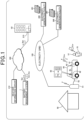
Figure 1 , an aspect of managing abattery 62 of avehicle 60 by abattery management system 1 of the present embodiment is described. Thebattery management system 1 virtually divides a capacity Ca of thebattery 62 mounted on thevehicle 60 into a first area C1 and a second area C2 as shown atcallout 65, and allocates the first area C1 to a vehicle user U1 and the second area C2 to an electricity provider U2. - Thus, the
battery management system 1 makes thebattery 62 available to the vehicle user U1 within the first area C1, makes thebattery 62 available to the electricity provider U2 within the second area C2, and thereby supporting more effective use of thebattery 62. Thevehicle 60 corresponds to a mobile object in the present disclosure, the vehicle user U1 corresponds to a first user in the present disclosure, and the electricity provider U2 corresponds to a second user in the present disclosure. Note that the capacity of thebattery 62 may be divided into three or more areas to be allocated to three or more users. - The
vehicle 60 is an electric vehicle (battery electric vehicle, plug-in hybrid electric vehicle, or the like) that uses thebattery 62 for a drive source, and is connected to charge-discharge equipment 51 attached toproperty 50, such as a home of the vehicle user U1, through a charge-discharge cable 52. Thebattery 62 is charged with electricity supplied from the charge-discharge equipment 51, and supplies electricity to the charge-discharge equipment 51, via the charge-discharge cable 52. - The charge-
discharge equipment 51 is connected to a plurality ofelectricity generation facilities 200 operated by the electricity provider U2 via anelectricity grid 100, and generated electricity is supplied from theelectricity generation facilities 200 to theelectricity grid 100. Thebattery 62 is charged with surplus generated electricity via the charge-discharge equipment 51, and when generated electricity to theelectricity grid 100 is in short supply, discharged electricity from thebattery 62 is supplied to theelectricity grid 100. Eachelectricity generation facility 200 generates electricity by using asolar panel 201. - The
battery management system 1 performs communication, via acommunication network 300, with avehicle control device 61, the charge-discharge equipment 51, acommunication terminal 70 used by the vehicle user U1, amanagement system 210 of the electricity provider U2, aweather information server 310, and the like. Thecommunication terminal 70 is a smartphone, a mobile phone, a tablet terminal, a notebook personal computer, a desktop personal computer, on-vehicle communication equipment including a car navigation system, or the like. - The
battery management system 1 transmits, to thevehicle control device 61, ratio instruction information Dvr for instructing a ratio setting of the first area C1 to the second area C2 in thebattery 62 be set (setting of a capacity of each area). Based on the ratio instruction information Dvr, thevehicle control device 61 performs control of the capacity in thebattery 62 in such a manner as to allocate the first area C1 for use by the vehicle user U1 (for discharge or regenerative charge accompanying electricity consumption by thevehicle 60, and charge from the charge-discharge equipment 51 based on an operation by the vehicle user U1), and allocate the second area C2 for use by the electricity provider U2 (for charge as a buffer against electricity generated by theelectricity generation facilities 200, and discharge accompanying electricity supply to the electricity grid 100) . - The
battery management system 1 performs a process of changing the capacities of the first area C1 and the second area C2 in thebattery 62, based on a request from the vehicle user U1, a request from the electricity provider U2, or an external factor such as an outside temperature around thevehicle 60 provided from theweather information server 310. For example, upon receiving capacity change request information Ccr that is transmitted from thecommunication terminal 70 of the vehicle user U1 and that requests an increase in the capacity of the first area C1, thebattery management system 1 determines whether or not a condition for acceptance based on acceptance condition information Awc transmitted from themanagement system 210 of the electricity provider U2 is satisfied. - When the capacity change request satisfies the condition for acceptance, the
battery management system 1 changes the capacities of the first area C1 and the second area C2 according to the capacity change request, and transmits, to thevehicle control device 61, ratio instruction information Dvr instructing that the capacities be changed. Thevehicle control device 61 having received the ratio instruction information Dvr reflects the changes in capacity of the first area C1 and the second area C2 in charge-discharge control of thebattery 62, and, on adisplay unit 63, makes a display indicating that the capacity of the first area C1 has increased. - Note that although one vehicle user U1 and one electricity provider U2 are depicted in
Figure 1 for explanatory convenience, thebattery management system 1 performs similar adjustment processes for a plurality of vehicle users and a plurality of electricity providers, with regard to divisional use of batteries mounted on a plurality of vehicles. - With reference to
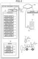
Figures 2 to 5 , a configuration of the battery management system is described. With reference toFigure 2 , thebattery management system 1 is a computer system including aprocessor 10, amemory 30, acommunication unit 40, and the like. Thecommunication unit 40 performs communication, via thecommunication network 300, with thevehicle control device 61, thecommunication terminal 70 used by the vehicle user U1, themanagement system 210 of the electricity provider U2, theweather information server 310, and the like. - The
memory 30 stores acontrol program 31 for thebattery management system 1, dividingratio data 32 indicating setting of a dividing ratio of the first area C1 to the second area C2 in the battery 62 (a setting of a capacity of each area), andacceptance condition data 33 indicating a condition for acceptance of a change in the capacity of the second area C2. The condition for acceptance is presented by the electricity provider U2. - The
processor 10 reads and executes thecontrol program 31 to function as a batterycapacity division section 11, a capacitychange reception section 12, a capacitychange adjustment section 13, an areacapacity change section 14, an outsidetemperature recognition section 15, an electricity consumptionamount prediction section 16, a capacitychange application section 17, and a capacitychange display section 18. - A process executed by the battery
capacity division section 11 corresponds to a battery capacity division step of a battery management method in the present disclosure, and a process executed by the capacitychange reception section 12 corresponds to a capacity change reception step of the battery management method in the present disclosure. A process executed by the capacitychange adjustment section 13 corresponds to a capacity change adjustment step of the battery management method in the present disclosure, and a process executed by the areacapacity change section 14 corresponds to an area capacity change step of the battery management method in the present disclosure. - The battery
capacity division section 11 virtually divides, as described above, the capacity Ca of thebattery 62 mounted on thevehicle 60 into the first area C1 allocated to the vehicle user U1, and the second area C2 allocated to the electricity provider U2, and stores thedividing ratio data 32 indicating a dividing ratio in thememory 30. The batterycapacity division section 11 transmits, to thevehicle control device 61, ratio instruction information Dvr instructing that thebattery 62 divided into the first area C1 and the second area C2 be used. - The capacity
change reception section 12 receives capacity change request information Ccr transmitted from thecommunication terminal 70 used by the vehicle user U1 and thus receives a capacity change request of the vehicle user U1 with regard to the first area C1. The capacitychange adjustment section 13 receives acceptance condition information Awc transmitted from themanagement system 210 of the electricity provider U2, and recognizes a condition for acceptance of a change in the capacity of the second area C2, which is set by the electricity provider U2. - For the condition for acceptance, for example, a first condition for acceptance and a second condition for acceptance as follows are set.
- First condition for acceptance: A predetermined consideration in exchange for a decrease in the capacity of the second area C2 is provided from the vehicle user U1 to the electricity provider U2.
- Second condition for acceptance: A period for which the capacity of the second area C2 is decreased is limited to a predetermined period (several days or the like) or less.
- The capacity
change adjustment section 13 stores theacceptance condition data 33 indicating the conditions for acceptance in thememory 30. When the capacity change request with regard to the first area C1 is received by the capacitychange reception section 12, the capacitychange adjustment section 13 determines whether or not the capacity of the second area C2 can be changed according to the capacity change request. Specifically, when the capacity change request satisfies the first condition for acceptance or the second condition for acceptance, the capacitychange adjustment section 13 determines that the capacity of the second area C2 can be changed according to the capacity change request. - When the capacity change request satisfies neither the first condition for acceptance nor the second condition for acceptance, the capacity
change adjustment section 13 transmits the capacity change request information to themanagement system 210, and inquires of the electricity provider U2 whether or not the capacity of the second area C2 can be changed according to the capacity change request. When capacity change approval information approving of a change in the capacity of the second area C2 according to the capacity change request is received from themanagement system 210, the capacitychange adjustment section 13 determines that the capacity of the second area C2 can be changed according to the capacity change request. - When the capacity
change adjustment section 13 determines that the capacity of the second area C2 can be changed according to the capacity change request, the areacapacity change section 14 changes the capacities of the first area C1 and the second area C2 according to the capacity change request. According to the changes, the batterycapacity division section 11 updates the dividingratio data 32 to data indicating a dividing ratio of the changed first area C1 to the changed second area C2, and transmits, to thevehicle control device 61, ratio instruction information Dvr instructing that thebattery 62 be used according to the changed dividing ratio. - The outside
temperature recognition section 15 recognizes an outside temperature around thevehicle 60, based on weather information on the vicinity of a position where thevehicle 60 is parked, which is provided from theweather information server 310, or verified temperature information obtained by an outside temperature sensor mounted on thevehicle 60, which is transmitted from thevehicle control device 61. The electricity consumptionamount prediction section 16 predicts power consumption by equipment included in the vehicle 60 (an air-conditioning system, a cooling system for temperature management of thebattery 62, or the like), based on the outside temperature around thevehicle 60 recognized by the outsidetemperature recognition section 15. For example, when the outside temperature is a low temperature that is a predetermined temperature or less, the electricity consumptionamount prediction section 16 predicts that electricity consumption will be high for heating by the air-conditioning system. - When the amount of variation in the amount of electricity consumption predicted by the electricity consumption
amount prediction section 16 is a predetermined value or more, the capacitychange application section 17 applies for a capacity change request to the capacitychange reception section 12. The capacity change request requests that the capacity of the first area C1 be changed according to the amount of variation in the amount of electricity consumption. Here, the amount of variation in the electricity consumption may be the amount of variation throughout periods in units such as one day or several days, and an application for a capacity change may have a content requesting that, for example, the first area C1 be increased for a period during which the amount of electricity consumption increases, such as for several months in winter. - In
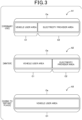
Figure 3 , A2 shows an example in which for a period during which the amount of electricity generated by thesolar panels 201 decreases while power consumption by equipment of thevehicle 60 increases in winter, the capacity of the first area C1 is increased and the capacity of the second area C2 is decreased, from settings for ordinary use in A1. A3 shows an example in which when the vehicle user U1 goes to a distant place by thevehicle 60, capacity change request information Ccr to increase the capacity of the first area C1 is transmitted from thecommunication terminal 70 to thebattery management system 1, and in response thereto, the capacity of the first area C1 is increased to the entire capacity Ca of thebattery 62. - The capacity
change display section 18 transmits, to thevehicle control device 61, display change information instructing that information indicating that the capacity of the first area C1 has been changed by the areacapacity change section 14 be displayed. When the display change information is received, thevehicle control device 61 makes a display indicating that the capacity of the first area C1 has been changed, on thedisplay unit 63 included in thevehicle 60. -
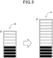
Figures 4 and5 show examples of the display made when the first area C1 has been changed.Figure 4 is an example of the display in which the capacity of the first area C1 is displayed, and is changed from X1 kWh shown in A4 to X2 kWh shown in A5.Figure 5 is an example of the display in which the size of a display area is changed, and when the capacity of the first area C1 is increased, the size of the display area for the remaining amount of stored electricity is increased from a size shown in A6 to a size shown in A7. - A procedure for changing the capacity of the first area C1, which is executed by the
battery management system 1 in a situation shown inFigures 1 and2 , is described by following a flowchart shown inFigure 6 . - Through loop processes in steps S1, S10 in
Figure 6 , when capacity change request information Ccr is received from thecommunication terminal 70 of the vehicle user U1 in step S1, or when an application for a capacity change is made as a result of the amount of variation in the amount of electricity consumption predicted by the electricity consumptionamount prediction section 16 becoming a predetermined value or more in step S10, the capacitychange reception section 12 moves the process to step S2. - In step S2, the capacity
change adjustment section 13 determines whether or not the content of a capacity change request according to the capacity change request information Ccr or the application for a capacity change satisfies the first condition for acceptance or the second condition for acceptance presented by the electricity provider U2. The capacitychange adjustment section 13 moves the process to step S20 when the content of the capacity change request satisfies the first condition for acceptance or the second condition for acceptance, and moves the process to step S3 when the content of the capacity change request satisfies neither the first condition for acceptance nor the second condition for acceptance. - In step S3, the capacity
change adjustment section 13 transmits the capacity change request information Ccr to themanagement system 210 of the electricity provider U2 and inquires of themanagement system 210 of the electricity provider U2 whether or not to approve of a change in the capacity of the second area C2 according to the capacity change request. In subsequent step S4, the capacitychange adjustment section 13 moves the process to step S20 when capacity change approval information approving of a change in the capacity of the second area C2 according to the capacity change request is received from themanagement system 210 of the electricity provider U2. - When the capacity change approval information is not received, the capacity
change adjustment section 13 moves the process to step S5, in which capacity change disapproval information notifying that a change in the capacity of the first area C1 according to the capacity change request is disapproved of is transmitted to thecommunication terminal 70 of the vehicle user U1. Thus, the notification that a change in the capacity of the first area C1 is disapproved of is displayed on a display unit of thecommunication terminal 70. - In step S20, the area
capacity change section 14 changes the capacities of the first area C1 and the second area C2, based on the capacity change request. In subsequent step S21, the batterycapacity division section 11 transmits, to thevehicle control device 61, ratio instruction information Dvr indicating a dividing ratio corresponding to the capacities of the first area C1 and the second area C2 changed by the areacapacity change section 14. Thus, control of thebattery 62 by thevehicle control device 61 is changed to control based on the changed dividing ratio. - In subsequent step S22, the capacity
change display section 18 transmits, to thevehicle control device 61, display change information instructing that the display of the remaining amount of stored electricity be changed according to the change in the capacity of the first area C1. Thevehicle control device 61 having received the display change information changes the displayed aspect of the remaining amount of stored electricity in the first area C1, as described above with reference toFigures 4 and5 . - In subsequent step S23, the capacity
change display section 18 transmits, to thecommunication terminal 70 of the vehicle user U1, capacity change execution information notifying that the capacity of the first area C1 has been changed. Thecommunication terminal 70 having received the capacity change execution information makes a display notifying that the capacity of the first area C1 has been changed, on the display unit of thecommunication terminal 70. Thus, it can be notified to the vehicle user U1 that the capacity of the first area C1 has been changed. - Although the embodiment illustrates the
vehicle 60 as a mobile object in the present disclosure, the mobile object in the present disclosure may be any mobile object that includes a battery that is charged and discharged by charge-discharge equipment, and may be an aircraft, a watercraft, or the like. - In the embodiment, a case is described in which a change in the capacity of the second area C2 allocated to the electricity provider U2 is adjusted in response to a capacity change request of the vehicle user U1 with regard to the first area C1. As another embodiment, a case where a change in the capacity of the first area C1 allocated to the vehicle user U1 is adjusted in response to a capacity change request of the electricity provider U2 with regard to the second area C2 can also be handled through similar processes. In such a case, the electricity provider U2 is a first user in the present disclosure, and the vehicle user U1 is a second user in the present disclosure.
- As one of conditions for acceptance of a capacity change request of the vehicle user U1 with regard to the first area C1 as illustrated in the embodiment, or as a condition added to the above-described conditions for acceptance, it may be set that an inquiry about whether or not to approve of a capacity change request of one user who shares use of the
battery 62 shall be made to another user, and an answer indicating approval of a capacity change shall be obtained from the other user. Thus, it is possible to flexibly and reliably adjust capacity changes. - In the embodiment, the outside
temperature recognition section 15, the electricity consumptionamount prediction section 16, and the capacitychange application section 17 are included, and the processes to change the capacity of the first area C1 are performed based on the amount of electricity consumption by equipment included in thevehicle 60. However, a configuration may be made that omits the outsidetemperature recognition section 15, the electricity consumptionamount prediction section 16, and the capacitychange application section 17. - In the embodiment, the capacity
change display section 18 is included, and when the capacity of the first area C1 is changed, information indicating that the capacity of the first area C1 has been changed is displayed on thedisplay unit 63 of thevehicle 60 or on the display unit of thecommunication terminal 70. However, a configuration may be made that omits the capacitychange display section 18. - In the embodiment, the
battery management system 1 in the present disclosure is configured by a computer system that performs communication with thevehicle 60 on which thebattery 62 is mounted. As another embodiment, the battery management system may be configured as a function of thevehicle control device 61. In such a case, a configuration is made such that communication is performed between thevehicle control device 61 and each of thecommunication terminal 70 of the vehicle user U1 and themanagement system 210 of the electricity provider U2. - Note that
Figure 2 is a schematic diagram showing functional structure of thebattery management system 1 that is segmented based on main processes, in order to facilitate the understanding of the invention of the present application, and the structure of thebattery management system 1 may be configured based on other segments. A process by each constituent element may be executed by one hardware unit, or may be executed by a plurality of hardware units. The process by each constituent element shown inFigure 6 may be executed by using one program, or may be executed by using a plurality of programs. - The embodiment is a specific example of following configurations.
- (Configuration 1) A battery management system including: a battery capacity division section that makes a battery mounted on a mobile object available to each user within an area allocated to the user, by virtually dividing a capacity of the battery into a predetermined number of areas, and individually allocating the areas to the predetermined number of users, ; a capacity change reception section that receives a capacity change request for requesting a change in a capacity of a first area, the first area being the area allocated to a first user that is any one user among the predetermined number of users; a capacity change adjustment section that, when the capacity change request is received by the capacity change reception section, determines whether or not a capacity of a second area can be changed according to the capacity change request, the second area being the area allocated to a second user other than the first user among the predetermined number of users; and an area capacity change section that, when the capacity change adjustment section determines that the capacity of the second area can be changed according to the capacity change request, changes the capacities of the first area and the second area according to the capacity change request.
- According to the battery management system in the
configuration 1, the capacity change adjustment section determines whether or not the capacity of the first area allocated to the first user can be changed, and the capacity of the first area is changed by the area capacity change section, whereby it is possible to support more effective use of the battery mounted in the mobile object. - (Configuration 2) The battery management system according to
configuration 1, wherein when the capacity change request satisfies a condition for acceptance, preset by the second user, of a change in the capacity of the second area, the capacity change adjustment section determines that the capacity of the second area can be changed according to the capacity change request. - According to the battery management system in the configuration 2, by presetting the condition for acceptance of a change in the capacity of the second area, it is possible to immediately change the capacities of the areas in the battery according to the capacity change request.
- (Configuration 3) The battery management system according to the configuration 2, wherein a condition that when a matter requested by the capacity change request is an increase in the capacity of the first area, the first user provides the second user with a predetermined consideration in exchange for a decrease in the capacity of the second area according to the capacity change request is set as the condition for acceptance.
- According to the battery management system in the configuration 3, by providing the predetermined consideration to the second user, it is possible to immediately increase the capacity of the first area and decrease the capacity of the second area according to the capacity change request.
- (Configuration 4) The battery management system according to configuration 2 or 3, wherein a condition that a matter requested by the capacity change request is a change in the capacity of the first area that is limited to a predetermined period or less is set as the condition for acceptance.
- According to the battery management system in the configuration 4, when a change in the capacity of the first area according to the capacity change request is for a short period, it is possible to immediately change the capacities of the first area and the second area, without performing a process for gaining consent of the second user.
- (Configuration 5) The battery management system according to any one of
configurations 1 to 4, including: an outside temperature recognition section that recognizes an outside temperature around the mobile object; an electricity consumption amount prediction section that predicts an amount of electricity consumption by equipment mounted on the mobile object, based on the outside temperature recognized by the outside temperature recognition section; and a capacity change application section that, when an amount of variation in the amount of electricity consumption predicted by the electricity consumption amount prediction section is a predetermined value or more, applies for the capacity change request to the capacity change reception section. - According to the battery management system in the
configuration 5, when the amount of electricity consumption by the equipment (an air-conditioning system, a cooling and heating system for the battery, or the like) that is supposed to consume electricity variably according to changes in outside temperature around the mobile object is the predetermined value or more, it is possible to efficiently change the capacities of the first area and the second area, without waiting for the first user to apply for a request to change the capacity of the first area. - (Configuration 6) The battery management system according to any one of
configurations 1 to 5, wherein the first user is a user of the mobile object, and the battery management system includes a capacity change display section that, when the capacity of the first area is changed by the area capacity change section, displays information indicating that the capacity of the first area is changed, on a first display unit displaying a state of charge of the first area, which is included in the mobile object, or a second display unit of a communication terminal used by the first user. - According to the battery management system in the configuration 6, it is possible to notify the first user of that the capacity of the first area is changed, through the display by using the first display unit included in the mobile object or the second display unit of the communication terminal.
- (Configuration 7) A battery management method that is executed by a computer, the battery management method including: a battery capacity division step of making a battery mounted on a mobile object available to each user within an area allocated to the user, by virtually dividing a capacity of the battery into a predetermined number of areas, and by individually allocating the areas to the predetermined number of users; a capacity change reception step of receiving a capacity change request for requesting a change in a capacity of a first area, the first area being the area allocated to a first user that is any one user among the predetermined number of users; a capacity change adjustment step of, when the capacity change request is received by the capacity change reception step, determining whether or not a capacity of a second area can be changed according to the capacity change request, the second area being the area allocated to a second user other than the first user among the predetermined number of users; and an area capacity change step of, when the capacity change adjustment step determines that the capacity of the second area can be changed according to the capacity change request, changing the capacities of the first area and the second area according to the capacity change request.
- By the computer executing the battery management method in configuration 7, it is possible to obtain similar operations and effects to those of the battery management system in
configuration 1. - 1 battery management system, 10 processor, 11 battery capacity division section, 12 capacity change reception section, 13 capacity change adjustment section, 14 area capacity change section, 15 outside temperature recognition section, 16 electricity consumption amount prediction section, 17 capacity change application section, 18 capacity change display section, 30 memory, 31 control program, 32 dividing ratio data, 33 acceptance condition data, 40 communication unit, 50 property, 51 charge-discharge equipment, 52 charge-discharge cable, 60 vehicle (mobile object), 61 vehicle control device, 62 battery, 63 vehicle display unit, 70 communication terminal, 100 electricity grid, 200 electricity generation facility, 201 solar panel, 210 management system of electricity provider, 300 communication network, 310 weather information server, U1 vehicle user (first user), U2 electricity provider (second user), C1 first area, C2 second area
Claims (7)
- A battery management system comprising:a battery capacity division section that makes a battery mounted on a mobile object available to each user within an area allocated to the user, by virtually dividing a capacity of the battery into a predetermined number of areas, and individually allocating the areas to the predetermined number of users;a capacity change reception section that receives a capacity change request for requesting a change in a capacity of a first area, the first area being the area allocated to a first user that is any one user among the predetermined number of users;a capacity change adjustment section that, when the capacity change request is received by the capacity change reception section, determines whether or not a capacity of a second area can be changed according to the capacity change request, the second area being the area allocated to a second user other than the first user among the predetermined number of users; andan area capacity change section that, when the capacity change adjustment section determines that the capacity of the second area can be changed according to the capacity change request, changes the capacities of the first area and the second area according to the capacity change request.
- The battery management system according to claim 1, wherein when the capacity change request satisfies a condition for acceptance, preset by the second user, of a change in the capacity of the second area, the capacity change adjustment section determines that the capacity of the second area can be changed according to the capacity change request.
- The battery management system according to claim 2, wherein a condition that when a matter requested by the capacity change request is an increase in the capacity of the first area, the first user provides the second user with a predetermined consideration in exchange for a decrease in the capacity of the second area according to the capacity change request is set as the condition for acceptance.
- The battery management system according to claim 2 or 3, wherein a condition that a matter requested by the capacity change request is a change in the capacity of the first area that is limited to a predetermined period or less is set as the condition for acceptance.
- The battery management system according to any one of claims 1 to 4, comprising:an outside temperature recognition section that recognizes an outside temperature around the mobile object;an electricity consumption amount prediction section that predicts an amount of electricity consumption by equipment mounted on the mobile object, based on the outside temperature recognized by the outside temperature recognition section; anda capacity change application section that, when an amount of variation in the amount of electricity consumption predicted by the electricity consumption amount prediction section is a predetermined value or more, applies for the capacity change request to the capacity change reception section.
- The battery management system according to any one of claims 1 to 5, whereinthe first user is a user of the mobile object, andthe battery management system comprises a capacity change display section that, when the capacity of the first area is changed by the area capacity change section, displays information indicating that the capacity of the first area is changed, by using a first display unit displaying a state of charge of the first area, which is included in the mobile object, or a second display unit of a communication terminal used by the first user.
- A battery management method that is executed by a computer, the battery management method comprising:a battery capacity division step of making a battery mounted on a mobile object available to each user within an area allocated to the user, by virtually dividing a capacity of the battery into a predetermined number of areas, and by individually allocating the areas to the predetermined number of users;a capacity change reception step of receiving a capacity change request for requesting a change in a capacity of a first area, the first area being the area allocated to a first user that is any one user among the predetermined number of users;a capacity change adjustment step of, when the capacity change request is received by the capacity change reception step, determining whether or not a capacity of a second area can be changed according to the capacity change request, the second area being the area allocated to a second user other than the first user among the predetermined number of users; andan area capacity change step of, when the capacity change adjustment step determines that the capacity of the second area can be changed according to the capacity change request, changing the capacities of the first area and the second area according to the capacity change request.
Applications Claiming Priority (1)
| Application Number | Priority Date | Filing Date | Title |
|---|---|---|---|
| PCT/JP2022/010926 WO2023170931A1 (en) | 2022-03-11 | 2022-03-11 | Battery management system, and battery management method |
Publications (2)
| Publication Number | Publication Date |
|---|---|
| EP4492628A1 true EP4492628A1 (en) | 2025-01-15 |
| EP4492628A4 EP4492628A4 (en) | 2025-04-23 |
Family
ID=87936471
Family Applications (1)
| Application Number | Title | Priority Date | Filing Date |
|---|---|---|---|
| EP22930912.5A Pending EP4492628A4 (en) | 2022-03-11 | 2022-03-11 | Battery management system, and battery management method |
Country Status (4)
| Country | Link |
|---|---|
| US (1) | US20250233436A1 (en) |
| EP (1) | EP4492628A4 (en) |
| JP (1) | JP7671916B2 (en) |
| WO (1) | WO2023170931A1 (en) |
Families Citing this family (1)
| Publication number | Priority date | Publication date | Assignee | Title |
|---|---|---|---|---|
| WO2025126490A1 (en) * | 2023-12-15 | 2025-06-19 | 日本電信電話株式会社 | Resource allocation system, resource allocation method, and program |
Family Cites Families (7)
| Publication number | Priority date | Publication date | Assignee | Title |
|---|---|---|---|---|
| JP2008141926A (en) * | 2006-12-05 | 2008-06-19 | Hitachi Ltd | Home power storage device, in-vehicle power storage device, power supply / storage system, and power storage control method |
| WO2017170741A1 (en) * | 2016-03-29 | 2017-10-05 | 京セラ株式会社 | Power management apparatus, power management system, and power management method |
| CN107662618A (en) * | 2016-07-29 | 2018-02-06 | 福特环球技术公司 | The system and method for energy source in the shared vehicle of management filling |
| JP6789866B2 (en) * | 2017-03-28 | 2020-11-25 | 京セラ株式会社 | Power storage device and power management system |
| JP7033965B2 (en) * | 2018-03-15 | 2022-03-11 | シャープ株式会社 | Power control device and power control method |
| JP7069352B2 (en) | 2019-01-17 | 2022-05-17 | 本田技研工業株式会社 | Capacity control device and program |
| US11167659B2 (en) * | 2019-02-05 | 2021-11-09 | Inventus Holdings, LLC. | Allocation of electrical energy within a storage cell |
-
2022
- 2022-03-11 WO PCT/JP2022/010926 patent/WO2023170931A1/en not_active Ceased
- 2022-03-11 US US18/844,598 patent/US20250233436A1/en active Pending
- 2022-03-11 JP JP2024505814A patent/JP7671916B2/en active Active
- 2022-03-11 EP EP22930912.5A patent/EP4492628A4/en active Pending
Also Published As
| Publication number | Publication date |
|---|---|
| US20250233436A1 (en) | 2025-07-17 |
| EP4492628A4 (en) | 2025-04-23 |
| JPWO2023170931A1 (en) | 2023-09-14 |
| JP7671916B2 (en) | 2025-05-02 |
| WO2023170931A1 (en) | 2023-09-14 |
Similar Documents
| Publication | Publication Date | Title |
|---|---|---|
| US20210096582A1 (en) | Conditioning an electric grid using electric vehicles | |
| EP2738644A2 (en) | Intelligent power monitoring | |
| US20160250942A1 (en) | Charging state management method, charging state management device, and program | |
| EP3016238A1 (en) | Charging state management method, charging state management device, and program | |
| WO2014209720A1 (en) | Techniques for adaptive demand/response energy management of electronic systems | |
| US20250233436A1 (en) | Battery management system, and battery management method | |
| JP2016046934A (en) | Power management system, regional power management device, consumer power management device | |
| WO2023111108A1 (en) | Network constraint energy management system for electric vehicle depot charging and scheduling | |
| US20240317100A1 (en) | Efficiently Charging Electric Vehicles Using a Battery-Based Charger | |
| US12248959B2 (en) | Battery replacement control device and battery replacement control system | |
| US20230302959A1 (en) | Battery management system and battery management method | |
| EP4492629A1 (en) | Battery management system and battery management method | |
| CN112994119B (en) | Power supply scheduling method and device, power supply system and storage medium | |
| CN112255949B (en) | Control architecture and control method of vehicle | |
| JP6645939B2 (en) | Information processing apparatus, information processing method and program | |
| JP6354666B2 (en) | Energy management system | |
| CN121280181A (en) | Charging/discharging management method, device, equipment, storage medium and program product for charging station | |
| US20250238267A1 (en) | Information processing device, information processing method, and non-transitory storage medium | |
| US20240070718A1 (en) | Server, system, and method | |
| CN119611003B (en) | Vehicle control method, device, equipment and storage medium based on power distribution | |
| CN119200699B (en) | Aircraft in-flight control method, storage medium, and computer program product | |
| US12397673B2 (en) | Server, system, and management method | |
| CN119726735B (en) | Power consumption control method, device, equipment, storage medium and product based on 5G technology | |
| CN118920521A (en) | Power distribution method, apparatus, storage medium, and program product | |
| JP2024016476A (en) | Power transfer system |
Legal Events
| Date | Code | Title | Description |
|---|---|---|---|
| STAA | Information on the status of an ep patent application or granted ep patent |
Free format text: STATUS: THE INTERNATIONAL PUBLICATION HAS BEEN MADE |
|
| PUAI | Public reference made under article 153(3) epc to a published international application that has entered the european phase |
Free format text: ORIGINAL CODE: 0009012 |
|
| STAA | Information on the status of an ep patent application or granted ep patent |
Free format text: STATUS: REQUEST FOR EXAMINATION WAS MADE |
|
| 17P | Request for examination filed |
Effective date: 20240903 |
|
| AK | Designated contracting states |
Kind code of ref document: A1 Designated state(s): AL AT BE BG CH CY CZ DE DK EE ES FI FR GB GR HR HU IE IS IT LI LT LU LV MC MK MT NL NO PL PT RO RS SE SI SK SM TR |
|
| A4 | Supplementary search report drawn up and despatched |
Effective date: 20250324 |
|
| RIC1 | Information provided on ipc code assigned before grant |
Ipc: G06Q 40/04 20120101ALI20250318BHEP Ipc: B60L 58/12 20190101ALI20250318BHEP Ipc: H02J 3/32 20060101ALI20250318BHEP Ipc: H02J 3/00 20060101ALI20250318BHEP Ipc: H02J 7/00 20060101ALI20250318BHEP Ipc: H02J 13/00 20060101AFI20250318BHEP |
|
| DAV | Request for validation of the european patent (deleted) | ||
| DAX | Request for extension of the european patent (deleted) | ||
| RAP3 | Party data changed (applicant data changed or rights of an application transferred) |
Owner name: HONDA MOTOR CO., LTD. |
|
| STAA | Information on the status of an ep patent application or granted ep patent |
Free format text: STATUS: EXAMINATION IS IN PROGRESS |
|
| 17Q | First examination report despatched |
Effective date: 20251222 |