EP4492413A1 - Wiring terminal and electromagnetic coil - Google Patents
Wiring terminal and electromagnetic coil Download PDFInfo
- Publication number
- EP4492413A1 EP4492413A1 EP23784232.3A EP23784232A EP4492413A1 EP 4492413 A1 EP4492413 A1 EP 4492413A1 EP 23784232 A EP23784232 A EP 23784232A EP 4492413 A1 EP4492413 A1 EP 4492413A1
- Authority
- EP
- European Patent Office
- Prior art keywords
- mounting
- section
- tab
- winding
- side wall
- Prior art date
- Legal status (The legal status is an assumption and is not a legal conclusion. Google has not performed a legal analysis and makes no representation as to the accuracy of the status listed.)
- Pending
Links
Images




Classifications
-
- H—ELECTRICITY
- H01—ELECTRIC ELEMENTS
- H01F—MAGNETS; INDUCTANCES; TRANSFORMERS; SELECTION OF MATERIALS FOR THEIR MAGNETIC PROPERTIES
- H01F5/00—Coils
- H01F5/04—Arrangements of electric connections to coils, e.g. leads
-
- H—ELECTRICITY
- H01—ELECTRIC ELEMENTS
- H01F—MAGNETS; INDUCTANCES; TRANSFORMERS; SELECTION OF MATERIALS FOR THEIR MAGNETIC PROPERTIES
- H01F27/00—Details of transformers or inductances, in general
- H01F27/28—Coils; Windings; Conductive connections
- H01F27/29—Terminals; Tapping arrangements for signal inductances
Definitions
- the present disclosure relates to the field of electromagnetic coils, and in particular to a terminal and an electromagnetic coil.
- an electromagnetic coil In the field of electromagnetic coil devices, an electromagnetic coil needs to be supported by a mechanical structure to realize a corresponding electromagnetic function, and needs to be energized to perform conversion between electricity and magnetism, and thus an electromagnetic coil device needs to use a corresponding electrical connection structure.
- a tin soldering process can be used to connect an enameled wire with left and right tabs.
- tin soldering process since tin cannot be directly applied onto tabs using a tin soldering process, the enameled wire and the left and right tabs cannot be directly electrically connected by means of tin soldering.
- the main object of some embodiments of the present disclosure is to provide a terminal and an electromagnetic coil, for solving the problem in the related art that an enameled wire and left and right tabs cannot be directly electrically connected by means of tin soldering.
- a terminal including: an insertion portion, the insertion portion being provided with an insertion cavity for allowing a tab to be inserted therein; and a winding body, the winding body being connected with the insertion portion, the winding body being provided with a winding portion for allowing a wire body to be wound thereon.
- the insertion portion includes two mounting plates disposed opposite each other, the insertion cavity is formed between the two mounting plates, and outer side walls of the two mounting plates are configured to be in interference fit with tab mounting holes of a framework structure of the electromagnetic coil; and/or the winding body is plate-shaped, and a protruding portion is provided on a plate surface of the winding portion, so as to cause the wire body wound on the winding portion to be in contact with the protruding portion.
- each of the two mounting plates includes a first mounting section and a second mounting section which are sequentially connected in a insertion direction of the tab, at least a part of the second mounting section protrudes relative to the first mounting section towards a side close to the insertion cavity, and an outer side wall of the second mounting section is configured to be in interference fit with a corresponding tab mounting hole.
- an end of the second mounting section far away from the first mounting section is provided with a protruding section, and in the insertion direction of the tab, a free end of the protruding section extends towards a side far away from the insertion cavity.
- a wall surface of a side of each of the two first mounting sections close to the insertion cavity is provided with a snap-fit protrusion, and the two first mounting sections, by means of snap-fit protrusions, are in interference fit with two outer side walls of the tab spaced apart from each other in a thickness direction of the tab; and/or outer wall surfaces of two second mounting sections abut against an inner wall surfaces of the tab mounting holes.
- the two first mounting sections are connected with the winding body, and both the two second mounting sections have a cantilever structure, such that the two second mounting sections can be deformably configured.
- the winding body has a Z-shaped structure formed by connecting three plate sections, and the insertion portion is connected with one plate section of the Z-shaped structure.
- the winding body includes an L-shaped plate section, the protruding portion has an L-shape, and the protruding portion extends along the L-shaped plate section.
- an electromagnetic coil including: a framework structure; a wire body, the wire body being wound on the framework structure; and the tabs and the terminals, the framework structure being provided with tab mounting holes for allowing the tabs and the terminals to be inserted therein.
- the framework structure includes a first framework section, an outer periphery of the first framework section is provided with a first side wall surface and a second side wall surface, at least a part of the second side wall surface is a curved surface, the first side wall surface is a flat surface, and two ends of the first side wall surface are respectively connected with two ends of the second side wall surface;
- the tab mounting holes are provided on the first side wall surface, and when the tabs and the terminals are inserted into the tab mounting holes, the winding portions of the winding bodies of the terminals protrude out of a plane where the first side wall surface is located;
- the framework structure includes a lead-out groove, the lead-out groove is located on the second side wall surface, both ends of the lead-out groove is provided with a lead-out opening, and the wire body is led out from the lead-out openings and then wound on the winding portions.
- the terminal of some embodiments of the present disclosure includes the insertion portion and the winding body, the insertion portion is provided with the insertion cavity for allowing the tab to be inserted therein, the winding body is connected to the insertion portion, and the winding body is provided with the winding portion for allowing the wire body to be wound thereon; and the winding body has a plate shape, and the protruding portion is provided on a plate surface of the winding portion, so as to cause the wire body wound on the winding portion to be in contact with the protruding portion.
- the wire body is wound on the protruding portion of the winding portion of the terminal, avoiding suspension of the wire body, increasing the contact area, and solving the problem in the related art that a terminal can negatively impact the winding quality of a wire body of an electromagnetic coil.
- the drawings contain the following reference signs: 1. insertion portion; 10. mounting plate; 11. first mounting section; 110. snap-fit protrusion; 12. second mounting section; 13. protruding section; 101. insertion cavity; 20. framework structure; 200. tab mounting hole; 201. first mounting hole section; 202. second mounting hole section; 21. first framework section; 22. second framework section; 23. third framework section; 210. first side wall surface; 211. second side wall surface; 220. lead-out groove; 221. lead-out opening; 100. tab; 30. winding body; 31. third mounting section; 32. connecting portion; 33. winding portion; 330. protruding portion; 300. wire body.
- some embodiments of the present disclosure provide a terminal, including: an insertion portion 1, the insertion portion 1 being provided with an insertion cavity 101 for allowing a tab 100 to be inserted therein; and a winding body 30, the winding body 30 being connected with the insertion portion 1, and the winding body 30 being provided with a winding portion 33 for allowing a wire body 300 to be wound thereon.
- the terminal in some embodiments of the present disclosure includes the insertion portion 1 and the winding body 30, the insertion portion 1 is provided with the insertion cavity 101 for allowing the tab 100 to be inserted therein, the winding body 30 is connected to the insertion portion 1, and the winding body 30 is provided with the winding portion 33 for allowing the wire body 300 to wound thereon.
- the wire body is wound on the winding portion 33, the tab 100 is inserted in the insertion cavity 101, and by means of the insertion portion 1 and the winding body 30, an enameled wire and the tab 100 can be electrically connected using tin solder, solving the problem in the prior art that tabs and an enameled wire cannot be directly electrically connected by means of tin soldering.
- the wire body 300 of some embodiments of the present disclosure is an enameled wire in an electromagnetic coil.
- the protruding surface of a protruding portion 330 is an arc-shaped surface.
- the insertion portion 1 includes two mounting plates 10 disposed opposite each other, the insertion cavity 101 is formed between the two mounting plates 10, and the outer side walls of the two mounting plates 10 are configured to be in interference fit with tab mounting holes 200 of a framework structure 20 of an electromagnetic coil; and/or the winding body 30 is plate-shaped, and the protruding portion 330 is provided on a plate surface of the winding portion 33, so as to cause the wire body 300 wound on the winding portion 33 to be in contact with the protruding portion 330.
- the wire body 300 is wound on the protruding portion 330 of the winding portion 33 of the terminal, avoiding suspension of the wire body, increasing the contact area, and improving the winding quality of the wire body of the electromagnetic coil.
- each of the two mounting plates 10 includes a first mounting section 11 and a second mounting section 12 which are sequentially connected in the insertion direction of the tab 100, at least a part of the second mounting section 12 protrudes relative to the first mounting section 11 towards the side close to the insertion cavity 101, and the outer side wall of the second mounting section 12 is configured to be in interference fit with the corresponding tab mounting hole 200.
- the end of the second mounting section 12 far away from the first mounting section 11 is provided with a protruding section 13, and in the insertion direction of the tab 100, a free end of the protruding section 13 extends towards the side far away from the insertion cavity 101.
- the wall surface of the side of each of the two first mounting sections 11 close to the insertion cavity 101 is provided with a snap-fit protrusion 110, and the two first mounting sections 11, by means of the snap-fit protrusions 110, are in interference fit with the two outer side walls of the tab 100 spaced apart from each other in the thickness direction of the tab 100; and/or the outer wall surfaces of the two second mounting sections 12 abut against the inner wall surfaces of the tab mounting holes 200.
- the free ends of the protruding sections 13 abut against the inner wall surfaces of the tab mounting holes 200.
- each snap-fit protrusion 110 protrudes towards the side close to the insertion cavity 101.
- each snap-fit protrusion 110 is an arc-shaped surface.
- the two first mounting sections 11 are connected with the winding body 30, and both the two second mounting sections 12 have a cantilever structure, such that the two second mounting sections 12 can be deformably configured.
- the winding body 30 has a Z-shaped structure formed by connecting three plate sections, and the insertion portion 1 is connected with one plate section of the Z-shaped structure.
- the winding body 30 further includes a third mounting section 31 and a connecting portion 32, the winding portion 33 and the third mounting section 31 are configured to be parallel to each other, and the connecting portion 32 and the winding portion 33 or the third mounting section 31 are configured to be perpendicular to each other.
- the insertion portion 1 is connected with the third mounting section 31 of the winding body 30.
- the plate surface of the third mounting section 31 is in contact connection with one side wall surface, in the width direction of the mounting plate 10, of each mounting plate 10 of the insertion portion 1; or each of the side wall surfaces of the third mounting section 31 in the width direction thereof is in contact connection with the inner wall surface of each mounting plate 10 of the mounting portion 1 close to the insertion cavity 101.
- the winding body 30 includes an L-shaped plate section, the L-shaped plate section is formed by the connecting portion 32 and the winding portion 33, the protruding portion 330 has an L shape, and the protruding portion 330 extends along the L-shaped plate section.
- the terminal of some embodiments of the present disclosure is made of copper.
- some embodiments of the present disclosure also provide an electromagnetic coil, including: a framework structure 20; a wire body 300, the wire body 300 being wound on the framework structure 20; and the tabs 100 and the terminals, the framework structure 20 being provided with tab mounting holes 200 for allowing the tabs 100 and the terminals to be inserted therein.
- the wire body 300 is an enameled wire.
- the framework structure 20 includes a first framework section 21, the outer periphery of the first framework section 21 is provided with a first side wall surface 210 and a second side wall surface 211, at least a part of the second side wall surface 211 is a curved surface, the first side wall surface 210 is a flat surface, and two ends of the first side wall surface 210 are respectively connected with two ends of the second side wall surface 211;
- the tab mounting holes 200 are provided on the first side wall surface 210, and when the tabs 100 and the terminals are inserted in the tab mounting holes 200, the winding portions 33 of the winding bodies 30 of the terminals protrude out of the plane where the first side wall surface 210 is located; and the framework structure 20 includes a lead-out groove 220, the lead-out groove 220 is located on the second side wall surface 211, both ends of the lead-out groove 220 are provided with a lead-out opening 221, and the wire body 300 is led out from the lead-out openings 221 and then wound on the winding
- the number of tab mounting holes 200 is two, the first side wall surface 210 has a stripe-shaped structure, and the two tab mounting holes 200 are respectively disposed at either end of the first side wall surface 210, so as to allow the winding portions 33 to be close to the lead-out openings 221, thereby avoiding suspension of the wire body 300 when the wire body is wound on the winding portions 33.
- each of the tab mounting holes 200 has an L-shaped structure
- each of the tab mounting holes 200 includes a first mounting hole section 201 and a second mounting hole section 202
- the first mounting hole section 201 is used for allowing the corresponding tab 100 to be inserted therein
- the second mounting hole section 202 is used for allowing the connecting portion 32 of the winding body 30 of the corresponding terminal to be inserted therein.
- the second mounting hole sections 202 of the two tab mounting holes 200 extend in opposite directions; and/or the second mounting hole sections 202 of the two tab mounting holes 200 are respectively located at two ends of the first mounting hole sections 201.
- the tabs 100 each has a Z-shaped structure, and can be directly plastic-encapsulated and led out and are connected with a junction box, without being connected with a junction box by means of connecting plates.
- the framework structure further includes a second framework section 22 and a third framework section 23, the first framework section 21, the second framework section 22, and the third framework section 23 jointly form an I-shaped structure, and the enameled wire is wound on the second framework section 22 and then led out by means of the lead-out groove 220 on the first framework section 21.
- the enameled wire is wound on the framework structure 20 and is led out by means of the lead-out groove 220 of the framework structure 20, and is secured by the terminals, the terminals being made of copper; in this way, the enameled wire can be electrically connected with the tabs 100 by means of the terminals using a tin soldering process, and the tabs 100 of the electromagnetic coil are connected with the enameled wire by means of interference insertion fitting with the terminals, achieving the production using a tin soldering process.
- the terminal in some embodiments of the present disclosure includes the insertion portion 1 and the winding body 30, the insertion portion 1 is provided with the insertion cavity 101 for allowing the tab 100 to be connected therein, the winding body 30 is connected with the insertion portion 1, and the winding body 30 is provided with the winding portion 33 for allowing the wire body 300 to be wound thereon; and the winding body 30 has a plate shape, and the protrusion 330 is provided on a plate surface of the winding portion 33, so as to cause the wire body 300 wound on the winding portion 33 to be in contact with the protrusion 330.
- the wire body 300 is wound on the protruding portion 330 of the winding portion 33 of the terminal, avoiding suspension of the wire body, increasing the contact area, and solving the problem in the related art that a terminal can negatively impact the winding quality of a wire body of an electromagnetic coil.
Landscapes
- Engineering & Computer Science (AREA)
- Power Engineering (AREA)
- Electromagnets (AREA)
- Coils Of Transformers For General Uses (AREA)
- Coils Or Transformers For Communication (AREA)
Abstract
Description
- The disclosure claims priority on the basis of patent application No.
202220796824.4, filed with the National Intellectual Property Administration, PRC on April 7, 2022 - The present disclosure relates to the field of electromagnetic coils, and in particular to a terminal and an electromagnetic coil.
- In the field of electromagnetic coil devices, an electromagnetic coil needs to be supported by a mechanical structure to realize a corresponding electromagnetic function, and needs to be energized to perform conversion between electricity and magnetism, and thus an electromagnetic coil device needs to use a corresponding electrical connection structure.
- In the related art, a tin soldering process can be used to connect an enameled wire with left and right tabs. However, since tin cannot be directly applied onto tabs using a tin soldering process, the enameled wire and the left and right tabs cannot be directly electrically connected by means of tin soldering.
- The main object of some embodiments of the present disclosure is to provide a terminal and an electromagnetic coil, for solving the problem in the related art that an enameled wire and left and right tabs cannot be directly electrically connected by means of tin soldering.
- In order to achieve the described object, according to one aspect of some embodiments of the present disclosure, provided is a terminal, including: an insertion portion, the insertion portion being provided with an insertion cavity for allowing a tab to be inserted therein; and a winding body, the winding body being connected with the insertion portion, the winding body being provided with a winding portion for allowing a wire body to be wound thereon.
- In some embodiments, the insertion portion includes two mounting plates disposed opposite each other, the insertion cavity is formed between the two mounting plates, and outer side walls of the two mounting plates are configured to be in interference fit with tab mounting holes of a framework structure of the electromagnetic coil; and/or the winding body is plate-shaped, and a protruding portion is provided on a plate surface of the winding portion, so as to cause the wire body wound on the winding portion to be in contact with the protruding portion.
- In some embodiments, each of the two mounting plates includes a first mounting section and a second mounting section which are sequentially connected in a insertion direction of the tab, at least a part of the second mounting section protrudes relative to the first mounting section towards a side close to the insertion cavity, and an outer side wall of the second mounting section is configured to be in interference fit with a corresponding tab mounting hole.
- In some embodiments, an end of the second mounting section far away from the first mounting section is provided with a protruding section, and in the insertion direction of the tab, a free end of the protruding section extends towards a side far away from the insertion cavity.
- In some embodiments, a wall surface of a side of each of the two first mounting sections close to the insertion cavity is provided with a snap-fit protrusion, and the two first mounting sections, by means of snap-fit protrusions, are in interference fit with two outer side walls of the tab spaced apart from each other in a thickness direction of the tab; and/or outer wall surfaces of two second mounting sections abut against an inner wall surfaces of the tab mounting holes.
- In some embodiments, the two first mounting sections are connected with the winding body, and both the two second mounting sections have a cantilever structure, such that the two second mounting sections can be deformably configured.
- In some embodiments, the winding body has a Z-shaped structure formed by connecting three plate sections, and the insertion portion is connected with one plate section of the Z-shaped structure.
- In some embodiments, the winding body includes an L-shaped plate section, the protruding portion has an L-shape, and the protruding portion extends along the L-shaped plate section.
- According to another aspect of some embodiments of the present disclosure, provided is an electromagnetic coil, including: a framework structure; a wire body, the wire body being wound on the framework structure; and the tabs and the terminals, the framework structure being provided with tab mounting holes for allowing the tabs and the terminals to be inserted therein.
- In some embodiments, the framework structure includes a first framework section, an outer periphery of the first framework section is provided with a first side wall surface and a second side wall surface, at least a part of the second side wall surface is a curved surface, the first side wall surface is a flat surface, and two ends of the first side wall surface are respectively connected with two ends of the second side wall surface; the tab mounting holes are provided on the first side wall surface, and when the tabs and the terminals are inserted into the tab mounting holes, the winding portions of the winding bodies of the terminals protrude out of a plane where the first side wall surface is located; the framework structure includes a lead-out groove, the lead-out groove is located on the second side wall surface, both ends of the lead-out groove is provided with a lead-out opening, and the wire body is led out from the lead-out openings and then wound on the winding portions.
- By applying the technical solution of some embodiments of the present disclosure, the terminal of some embodiments of the present disclosure includes the insertion portion and the winding body, the insertion portion is provided with the insertion cavity for allowing the tab to be inserted therein, the winding body is connected to the insertion portion, and the winding body is provided with the winding portion for allowing the wire body to be wound thereon; and the winding body has a plate shape, and the protruding portion is provided on a plate surface of the winding portion, so as to cause the wire body wound on the winding portion to be in contact with the protruding portion. In this way, the wire body is wound on the protruding portion of the winding portion of the terminal, avoiding suspension of the wire body, increasing the contact area, and solving the problem in the related art that a terminal can negatively impact the winding quality of a wire body of an electromagnetic coil.
- The drawings constituting a part of the description of the present disclosure are intended to provide better understanding of the present disclosure, and the schematic embodiments of the present disclosure and the description thereof are used to explain the present disclosure, but not to limit the present disclosure improperly. In the drawings:
-
Fig. 1 illustrates a structural schematic diagram of a first view of an embodiment of a terminal of the present disclosure; -
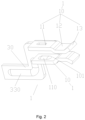
Fig. 2 illustrates a structural schematic diagram of a second view of an embodiment of a terminal of the present disclosure; -
Fig. 3 illustrates a structural schematic diagram of a third view of an embodiment of a terminal of the present disclosure; -
Fig. 4 illustrates a structural schematic diagram of fitting between a tab and a terminal according to an embodiment of a terminal of the present disclosure; -
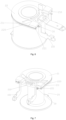
Fig. 5 illustrates a whole structural schematic diagram of a framework structure according to an embodiment of an electromagnetic coil of the present disclosure; -
Fig. 6 illustrates a structural schematic diagram of a first view of a wire body being wound on terminals according to an embodiment of an electromagnetic coil of the present disclosure; -
Fig. 7 illustrates a structural schematic diagram of a second view of a wire body being wound on terminals according to an embodiment of an electromagnetic coil of the present disclosure; and -
Fig. 8 illustrates a side view of a wire body being wound on terminals according to an embodiment of an electromagnetic coil of the present disclosure. - The drawings contain the following reference signs:
1. insertion portion; 10. mounting plate; 11. first mounting section; 110. snap-fit protrusion; 12. second mounting section; 13. protruding section; 101. insertion cavity; 20. framework structure; 200. tab mounting hole; 201. first mounting hole section; 202. second mounting hole section; 21. first framework section; 22. second framework section; 23. third framework section; 210. first side wall surface; 211. second side wall surface; 220. lead-out groove; 221. lead-out opening; 100. tab; 30. winding body; 31. third mounting section; 32. connecting portion; 33. winding portion; 330. protruding portion; 300. wire body. - It should be noted that, without conflict, the embodiments and the features of embodiments of the present disclosure can be combined. The embodiments of the present disclosure are described in detail with reference to the drawings combined with the embodiments.
- Referring to
Fig. 1 to Fig. 4 , some embodiments of the present disclosure provide a terminal, including: an insertion portion 1, the insertion portion 1 being provided with aninsertion cavity 101 for allowing atab 100 to be inserted therein; and awinding body 30, thewinding body 30 being connected with the insertion portion 1, and thewinding body 30 being provided with a windingportion 33 for allowing awire body 300 to be wound thereon. - The terminal in some embodiments of the present disclosure includes the insertion portion 1 and the
winding body 30, the insertion portion 1 is provided with theinsertion cavity 101 for allowing thetab 100 to be inserted therein, thewinding body 30 is connected to the insertion portion 1, and thewinding body 30 is provided with thewinding portion 33 for allowing thewire body 300 to wound thereon. In this way, the wire body is wound on the windingportion 33, thetab 100 is inserted in theinsertion cavity 101, and by means of the insertion portion 1 and thewinding body 30, an enameled wire and thetab 100 can be electrically connected using tin solder, solving the problem in the prior art that tabs and an enameled wire cannot be directly electrically connected by means of tin soldering. - The
wire body 300 of some embodiments of the present disclosure is an enameled wire in an electromagnetic coil. - In some embodiments, the protruding surface of a protruding
portion 330 is an arc-shaped surface. - In some embodiments, the insertion portion 1 includes two mounting
plates 10 disposed opposite each other, theinsertion cavity 101 is formed between the two mountingplates 10, and the outer side walls of the two mountingplates 10 are configured to be in interference fit withtab mounting holes 200 of aframework structure 20 of an electromagnetic coil; and/or the windingbody 30 is plate-shaped, and the protrudingportion 330 is provided on a plate surface of the windingportion 33, so as to cause thewire body 300 wound on the windingportion 33 to be in contact with the protrudingportion 330. In this way, thewire body 300 is wound on the protrudingportion 330 of the windingportion 33 of the terminal, avoiding suspension of the wire body, increasing the contact area, and improving the winding quality of the wire body of the electromagnetic coil. - As shown in
Fig. 1 to Fig. 3 , each of the two mountingplates 10 includes afirst mounting section 11 and asecond mounting section 12 which are sequentially connected in the insertion direction of thetab 100, at least a part of thesecond mounting section 12 protrudes relative to the first mountingsection 11 towards the side close to theinsertion cavity 101, and the outer side wall of thesecond mounting section 12 is configured to be in interference fit with the correspondingtab mounting hole 200. - In some embodiments, there is a guide angle between the first mounting
section 11 and thesecond mounting section 12. - In some embodiments, the end of the
second mounting section 12 far away from the first mountingsection 11 is provided with a protrudingsection 13, and in the insertion direction of thetab 100, a free end of the protrudingsection 13 extends towards the side far away from theinsertion cavity 101. - In some embodiments, there is a guide angle between the protruding
section 13 and thesecond mounting section 12. - In some embodiments, the wall surface of the side of each of the two first mounting
sections 11 close to theinsertion cavity 101 is provided with a snap-fit protrusion 110, and the two first mountingsections 11, by means of the snap-fit protrusions 110, are in interference fit with the two outer side walls of thetab 100 spaced apart from each other in the thickness direction of thetab 100; and/or the outer wall surfaces of the two second mountingsections 12 abut against the inner wall surfaces of thetab mounting holes 200. - In some embodiments, the free ends of the protruding
sections 13 abut against the inner wall surfaces of thetab mounting holes 200. - In some embodiments, each snap-
fit protrusion 110 protrudes towards the side close to theinsertion cavity 101. - In some embodiments, the surface of each snap-
fit protrusion 110 is an arc-shaped surface. - In some embodiments, the two first mounting
sections 11 are connected with the windingbody 30, and both the two second mountingsections 12 have a cantilever structure, such that the two second mountingsections 12 can be deformably configured. - In some embodiments of the present disclosure, the winding
body 30 has a Z-shaped structure formed by connecting three plate sections, and the insertion portion 1 is connected with one plate section of the Z-shaped structure. - In some embodiments, the winding
body 30 further includes athird mounting section 31 and a connectingportion 32, the windingportion 33 and the third mountingsection 31 are configured to be parallel to each other, and the connectingportion 32 and the windingportion 33 or the third mountingsection 31 are configured to be perpendicular to each other. - In some embodiments, the insertion portion 1 is connected with the third mounting
section 31 of the windingbody 30. - In some embodiments, the plate surface of the third mounting
section 31 is in contact connection with one side wall surface, in the width direction of the mountingplate 10, of each mountingplate 10 of the insertion portion 1; or each of the side wall surfaces of the third mountingsection 31 in the width direction thereof is in contact connection with the inner wall surface of each mountingplate 10 of the mounting portion 1 close to theinsertion cavity 101. - In some embodiments, the winding
body 30 includes an L-shaped plate section, the L-shaped plate section is formed by the connectingportion 32 and the windingportion 33, the protrudingportion 330 has an L shape, and the protrudingportion 330 extends along the L-shaped plate section. - In some embodiments, the terminal of some embodiments of the present disclosure is made of copper.
- Referring to
Fig. 5 to Fig. 8 , some embodiments of the present disclosure also provide an electromagnetic coil, including: aframework structure 20; awire body 300, thewire body 300 being wound on theframework structure 20; and thetabs 100 and the terminals, theframework structure 20 being provided withtab mounting holes 200 for allowing thetabs 100 and the terminals to be inserted therein. - In some embodiments, the
wire body 300 is an enameled wire. - In some embodiments, the
framework structure 20 includes afirst framework section 21, the outer periphery of thefirst framework section 21 is provided with a firstside wall surface 210 and a secondside wall surface 211, at least a part of the secondside wall surface 211 is a curved surface, the firstside wall surface 210 is a flat surface, and two ends of the firstside wall surface 210 are respectively connected with two ends of the secondside wall surface 211; thetab mounting holes 200 are provided on the firstside wall surface 210, and when thetabs 100 and the terminals are inserted in thetab mounting holes 200, the windingportions 33 of the windingbodies 30 of the terminals protrude out of the plane where the firstside wall surface 210 is located; and theframework structure 20 includes a lead-outgroove 220, the lead-outgroove 220 is located on the secondside wall surface 211, both ends of the lead-outgroove 220 are provided with a lead-outopening 221, and thewire body 300 is led out from the lead-outopenings 221 and then wound on the windingportions 33. - As shown in
Fig. 5 , the number oftab mounting holes 200 is two, the firstside wall surface 210 has a stripe-shaped structure, and the twotab mounting holes 200 are respectively disposed at either end of the firstside wall surface 210, so as to allow the windingportions 33 to be close to the lead-outopenings 221, thereby avoiding suspension of thewire body 300 when the wire body is wound on the windingportions 33. - In some embodiments, each of the
tab mounting holes 200 has an L-shaped structure, each of thetab mounting holes 200 includes a first mountinghole section 201 and a secondmounting hole section 202, the first mountinghole section 201 is used for allowing thecorresponding tab 100 to be inserted therein, and the secondmounting hole section 202 is used for allowing the connectingportion 32 of the windingbody 30 of the corresponding terminal to be inserted therein. - In some embodiments, the second mounting
hole sections 202 of the twotab mounting holes 200 extend in opposite directions; and/or the second mountinghole sections 202 of the twotab mounting holes 200 are respectively located at two ends of the first mountinghole sections 201. - In some embodiments of the present disclosure, the
tabs 100 each has a Z-shaped structure, and can be directly plastic-encapsulated and led out and are connected with a junction box, without being connected with a junction box by means of connecting plates. - In some embodiments, the framework structure further includes a
second framework section 22 and athird framework section 23, thefirst framework section 21, thesecond framework section 22, and thethird framework section 23 jointly form an I-shaped structure, and the enameled wire is wound on thesecond framework section 22 and then led out by means of the lead-outgroove 220 on thefirst framework section 21. - In the specific implementation process of some embodiments of the present disclosure, the enameled wire is wound on the
framework structure 20 and is led out by means of the lead-outgroove 220 of theframework structure 20, and is secured by the terminals, the terminals being made of copper; in this way, the enameled wire can be electrically connected with thetabs 100 by means of the terminals using a tin soldering process, and thetabs 100 of the electromagnetic coil are connected with the enameled wire by means of interference insertion fitting with the terminals, achieving the production using a tin soldering process. - From the description above, it can be determined that some embodiments of the present application achieve the following technical effects:
the terminal in some embodiments of the present disclosure includes the insertion portion 1 and the windingbody 30, the insertion portion 1 is provided with theinsertion cavity 101 for allowing thetab 100 to be connected therein, the windingbody 30 is connected with the insertion portion 1, and the windingbody 30 is provided with the windingportion 33 for allowing thewire body 300 to be wound thereon; and the windingbody 30 has a plate shape, and theprotrusion 330 is provided on a plate surface of the windingportion 33, so as to cause thewire body 300 wound on the windingportion 33 to be in contact with theprotrusion 330. In this way, thewire body 300 is wound on the protrudingportion 330 of the windingportion 33 of the terminal, avoiding suspension of the wire body, increasing the contact area, and solving the problem in the related art that a terminal can negatively impact the winding quality of a wire body of an electromagnetic coil. - The content above merely relates to preferred embodiments of the present disclosure and is not intended to limit the present disclosure. For a person skilled in the art, the present disclosure may have various modifications and variations. Any modifications, equivalent replacements, improvements, etc. made within the spirit and principle of the present disclosure shall all belong to the scope of protection of the present disclosure.
Claims (10)
- A terminal, comprising:an insertion portion (1), the insertion portion (1) being provided with an insertion cavity (101) for allowing a tab (100) to be inserted therein; anda winding body (30), the winding body (30) being connected with the insertion portion (1), and the winding body (30) being provided with a winding portion (33) for allowing a wire body (300) to be wound thereon.
- The terminal according to claim 1, wherein
the insertion portion (1) comprises two mounting plates (10) disposed opposite each other, the insertion cavity (101) is formed between the two mounting plates (10), and outer side walls of the two mounting plates (10) are configured to be in interference fit with tab mounting holes (200) of a framework structure (20) of an electromagnetic coil; and/or the winding body (30) is plate-shaped, and a protruding portion (330) is provided on a plate surface of the winding portion (33), so as to cause the wire body (300) wound on the winding portion (33) to be in contact with the protruding portion (330). - The terminal according to claim 2, wherein
each of the two mounting plates (10) comprises a first mounting section (11) and a second mounting section (12) which are sequentially connected in a insertion direction of the tab (100), at least a part of the second mounting section (12) protrudes relative to the first mounting section (11) towards a side close to the insertion cavity (101), and an outer side wall of the second mounting section (12) is configured to be in interference fit with a corresponding tab mounting hole (200). - The terminal according to claim 3, wherein
an end of the second mounting section (12) far away from the first mounting section (11) is provided with a protruding section (13), and in the insertion direction of the tab (100), a free end of the protruding section (13) extends towards a side far away from the insertion cavity (101). - The terminal according to claim 3, wherein
a wall surface of a side of each of two first mounting sections (11) close to the insertion cavity (101) is provided with a snap-fit protrusion (110), and the two first mounting sections (11), by means of snap-fit protrusions (110), are in interference fit with two outer side walls of the tab (100) spaced apart from each other in a thickness direction of the tab (100); and/or outer wall surfaces of two second mounting sections (12) abut against an inner wall surfaces of the tab mounting holes (200). - The terminal according to claim 3, wherein
two first mounting sections (11) are connected with the winding body (30), and both two second mounting sections (12) have a cantilever structure, such that the two second mounting sections (12) can be deformably configured. - The terminal according to claim 1, wherein
the winding body (30) has a Z-shaped structure formed by connecting three plate sections, and the insertion portion (1) is connected with one plate section of the Z-shaped structure. - The terminal according to claim 2, wherein
the winding body (30) comprises an L-shaped plate section, the protruding portion (330) has an L shape, and the protruding portion (330) extends along the L-shaped plate section. - An electromagnetic coil, comprising:a framework structure (20);a wire body (300), the wire body (300) being wound on the framework structure (20); andtabs (100) and the terminals according to any one of claims 1-8, the framework structure (20) being provided with tab mounting holes (200) for allowing the tabs (100) and the terminals to be inserted therein.
- The electromagnetic coil according to claim 9, whereinthe framework structure (20) comprises a first framework section (21), an outer periphery of the first framework section (21) is provided with a first side wall surface (210) and a second side wall surface (211), at least a part of the second side wall surface (211) is a curved surface, the first side wall surface (210) is a flat surface, and two ends of the first side wall surface (210) are respectively connected with two ends of the second side wall surface (211);the tab mounting holes (200) are provided on the first side wall surface (210), and when the tabs (100) and the terminals are inserted into the tab mounting holes (200), the winding portions (33) of the winding bodies (30) of the terminals protrude out of a plane where the first side wall surface (210) is located; andthe framework structure (20) comprises a lead-out groove (220), the lead-out groove (220) is located on the second side wall surface (211), both ends of the lead-out groove (220) are provided with a lead-out opening (221), and the wire body (300) is led out from the lead-out openings (221) and then wound on the winding portions (33).
Applications Claiming Priority (2)
| Application Number | Priority Date | Filing Date | Title |
|---|---|---|---|
| CN202220796824.4U CN217306279U (en) | 2022-04-07 | 2022-04-07 | Wiring terminal and electromagnetic coil |
| PCT/CN2023/085684 WO2023193668A1 (en) | 2022-04-07 | 2023-03-31 | Wiring terminal and electromagnetic coil |
Publications (2)
| Publication Number | Publication Date |
|---|---|
| EP4492413A1 true EP4492413A1 (en) | 2025-01-15 |
| EP4492413A4 EP4492413A4 (en) | 2025-07-02 |
Family
ID=82938754
Family Applications (1)
| Application Number | Title | Priority Date | Filing Date |
|---|---|---|---|
| EP23784232.3A Pending EP4492413A4 (en) | 2022-04-07 | 2023-03-31 | CONNECTION TERMINAL AND ELECTROMAGNETIC COIL |
Country Status (4)
| Country | Link |
|---|---|
| US (1) | US20250246360A1 (en) |
| EP (1) | EP4492413A4 (en) |
| CN (1) | CN217306279U (en) |
| WO (1) | WO2023193668A1 (en) |
Families Citing this family (2)
| Publication number | Priority date | Publication date | Assignee | Title |
|---|---|---|---|---|
| CN217306279U (en) * | 2022-04-07 | 2022-08-26 | 浙江盾安禾田金属有限公司 | Wiring terminal and electromagnetic coil |
| CN115732198B (en) * | 2022-11-22 | 2025-03-25 | 佛山市欧立电子有限公司 | An isolation transformer with a parent-child structure and 250 terminals and overheat protection |
Family Cites Families (11)
| Publication number | Priority date | Publication date | Assignee | Title |
|---|---|---|---|---|
| JPH0726806Y2 (en) * | 1992-01-30 | 1995-06-14 | 愛知電機株式会社 | Coil bobbins for electrical equipment |
| JP2001155928A (en) * | 1999-11-30 | 2001-06-08 | Mitsumi Electric Co Ltd | Trance |
| JP3986957B2 (en) * | 2000-08-18 | 2007-10-03 | 三菱電機株式会社 | Lamp transformer |
| DE102012212617A1 (en) * | 2012-07-18 | 2014-01-23 | Robert Bosch Gmbh | Electrical connection arrangement for an ignition coil |
| JP6486667B2 (en) * | 2014-11-28 | 2019-03-20 | 株式会社ユーシン | Connection structure of coil device |
| US10940848B2 (en) * | 2017-02-17 | 2021-03-09 | Nissin Kogyo Co., Ltd. | Electric component assembly, and brake fluid pressure control device for vehicle |
| CN210136773U (en) * | 2019-08-30 | 2020-03-10 | 合兴汽车电子股份有限公司 | Coil skeleton texture |
| JP7186446B2 (en) * | 2019-09-19 | 2022-12-09 | 株式会社不二工機 | Resin mold solenoid coil and solenoid valve with the same |
| CN211720446U (en) * | 2020-01-21 | 2020-10-20 | 上海华银电器有限公司 | Adjustable winding former for winding stator coil |
| CN213025958U (en) * | 2020-09-17 | 2021-04-20 | 德力西电气有限公司 | Wiring structure of contactor coil |
| CN217306279U (en) * | 2022-04-07 | 2022-08-26 | 浙江盾安禾田金属有限公司 | Wiring terminal and electromagnetic coil |
-
2022
- 2022-04-07 CN CN202220796824.4U patent/CN217306279U/en active Active
-
2023
- 2023-03-31 US US18/854,056 patent/US20250246360A1/en active Pending
- 2023-03-31 EP EP23784232.3A patent/EP4492413A4/en active Pending
- 2023-03-31 WO PCT/CN2023/085684 patent/WO2023193668A1/en not_active Ceased
Also Published As
| Publication number | Publication date |
|---|---|
| US20250246360A1 (en) | 2025-07-31 |
| CN217306279U (en) | 2022-08-26 |
| EP4492413A4 (en) | 2025-07-02 |
| WO2023193668A1 (en) | 2023-10-12 |
Similar Documents
| Publication | Publication Date | Title |
|---|---|---|
| EP4492413A1 (en) | Wiring terminal and electromagnetic coil | |
| EP0025605A1 (en) | Inductance device | |
| US8878640B2 (en) | Common-mode choke coil | |
| CN111128525B (en) | Magnetic conduction core body, wireless charging coil assembly and wireless charging device | |
| JPS60260116A (en) | Transformer | |
| US2802193A (en) | Electrical terminal connector | |
| KR102143868B1 (en) | Flat type transformer | |
| JP5963044B2 (en) | Core case unit and coil parts | |
| US4912448A (en) | Coil device with coil and lead terminals | |
| CN224020583U (en) | A side-leaded magnetic device | |
| CN223986738U (en) | Protruding thorn type terminal and magnetic device | |
| US3603907A (en) | Sealed reed relay | |
| KR20030094990A (en) | The second coil inserting type transformer and transbobin used therefor | |
| CN223450675U (en) | Semi-magnetic components and electromagnetic devices with both consistency and stability | |
| TWI876655B (en) | Skeleton and transformer | |
| CN223450676U (en) | Semi-magnetic part with stable terminal adhesion and electromagnetic device | |
| CN223986739U (en) | Surface mount terminal and magnetic device | |
| CN120072483A (en) | Side lead type magnetic device | |
| CN213366345U (en) | Wiring base, miniature transformer and power module | |
| CN222885067U (en) | Electromagnetic component and electrical module | |
| JP7783761B2 (en) | Coil Device | |
| CN117524661A (en) | Magnetic device | |
| CN119581192A (en) | Electromagnetic device and method for manufacturing the same | |
| CN210928165U (en) | Printed circuit board | |
| JPS6025865Y2 (en) | Electric circuit components including inductive elements |
Legal Events
| Date | Code | Title | Description |
|---|---|---|---|
| STAA | Information on the status of an ep patent application or granted ep patent |
Free format text: STATUS: THE INTERNATIONAL PUBLICATION HAS BEEN MADE |
|
| PUAI | Public reference made under article 153(3) epc to a published international application that has entered the european phase |
Free format text: ORIGINAL CODE: 0009012 |
|
| STAA | Information on the status of an ep patent application or granted ep patent |
Free format text: STATUS: REQUEST FOR EXAMINATION WAS MADE |
|
| 17P | Request for examination filed |
Effective date: 20241011 |
|
| AK | Designated contracting states |
Kind code of ref document: A1 Designated state(s): AL AT BE BG CH CY CZ DE DK EE ES FI FR GB GR HR HU IE IS IT LI LT LU LV MC ME MK MT NL NO PL PT RO RS SE SI SK SM TR |
|
| A4 | Supplementary search report drawn up and despatched |
Effective date: 20250603 |
|
| RIC1 | Information provided on ipc code assigned before grant |
Ipc: H01F 27/28 20060101ALI20250527BHEP Ipc: H01F 27/30 20060101ALI20250527BHEP Ipc: H01F 27/29 20060101AFI20250527BHEP |
|
| DAV | Request for validation of the european patent (deleted) | ||
| DAX | Request for extension of the european patent (deleted) |