EP4492372A1 - Damper device, structurally damped structure, and method - Google Patents
Damper device, structurally damped structure, and method Download PDFInfo
- Publication number
- EP4492372A1 EP4492372A1 EP23275103.2A EP23275103A EP4492372A1 EP 4492372 A1 EP4492372 A1 EP 4492372A1 EP 23275103 A EP23275103 A EP 23275103A EP 4492372 A1 EP4492372 A1 EP 4492372A1
- Authority
- EP
- European Patent Office
- Prior art keywords
- abh
- damper device
- characteristic
- primary structure
- variation
- Prior art date
- Legal status (The legal status is an assumption and is not a legal conclusion. Google has not performed a legal analysis and makes no representation as to the accuracy of the status listed.)
- Ceased
Links
Images

Classifications
-
- G—PHYSICS
- G10—MUSICAL INSTRUMENTS; ACOUSTICS
- G10K—SOUND-PRODUCING DEVICES; METHODS OR DEVICES FOR PROTECTING AGAINST, OR FOR DAMPING, NOISE OR OTHER ACOUSTIC WAVES IN GENERAL; ACOUSTICS NOT OTHERWISE PROVIDED FOR
- G10K11/00—Methods or devices for transmitting, conducting or directing sound in general; Methods or devices for protecting against, or for damping, noise or other acoustic waves in general
- G10K11/16—Methods or devices for protecting against, or for damping, noise or other acoustic waves in general
Definitions
- the present invention relates to a damper device, a structurally damped structure, and method of damping a primary structure.
- ABS acoustic black hole
- An acoustic black hole was originally described by Mironov in 1988 ( M.A. Mironov. Propagation of a flexural wave in a plate whose thickness decreases smoothly to zero in a finite interval.
- the acoustic black hole effect is typically achieved by introducing a power law taper into a beam or plate that changes the thickness over a set distance. This change in thickness profile causes the flexural waves propagating along the direction of the ABH to decrease in wave speed. In the theoretical limit, there is no reflection of the waves from the ABH.
- the ABH effect can also be achieved using other gradient functions, including a power-cosine curve, for example.
- Figure 1 shows an example of an ABH 1 on a beam 2.
- the ABH 1 is provided with a layer of damping material 3.
- E the Young's modulus of the ABH material
- h(x) the height of the taper
- ⁇ s is the density of the ABH material
- ⁇ is the angular frequency.
- acoustic black holes are known in the art.
- ⁇ Higher-order WKB analysis of reflection from tapered elastic wedges' Journal of Sound and Vibration 449 (2019) 368-388 Angelis Karlos, Stephen J. Elliot, Jordan Cheer ), the contents of which are incorporated herein, provides examples of different types of 'one-dimensional' acoustic black holes.
- damper devices comprising ABHs as an add-on for a beam. These add-ons are attached to the beam at an edge of the beam. Whilst advantageous in providing damping, the ABH is susceptible to damage. As examples, damage may be caused by contact with surrounding components, or by stress-related weaking over time and operation. Additionally, the ABH may degrade due to exposure to air or contaminants. Furthermore, damping material is typically provided, which, whilst improving damping performance of the ABH, it would be desirable to further improve damping performance where possible. To widen the potential applications of ABHs, it is desirable to overcome these limitations.
- prior art ABHs typically have a limited frequency response. That is, prior art ABHs are typically configured to control vibration of a particular frequency, or vibration within a narrow frequency band. It is desirable to improve control over a range of frequencies.
- a damper device for providing damping of a primary structure comprising: a body comprising a first surface and a second surface; and a first acoustic black hole, ABH, provided in the body at the first surface of the body, the first ABH having an asymmetric variation in characteristic.
- the first ABH comprises: in a first axis, a first variation in characteristic, in a first direction; and in the first axis, a second variation in characteristic, in a second direction opposite to the first direction, wherein the first variation and second variation are different.
- the asymmetric variation in characteristic is such that the first ABH is configured to control a plurality of vibrational modes.
- the asymmetric variation in characteristic is provided thereby to broaden the frequency response, or bandwidth, of the first ABH.
- the asymmetric variation in characteristic is provided thereby to increase a level of coupling with vibration of the primary structure.
- the asymmetric variation in characteristic controls or defines (for use) a plurality of vibrational control modes.
- the first surface of the body is adapted to contact, in a facing manner, a surface of the primary structure.
- the body is planar.
- the body is a plate.
- the first surface is a first surface of the plate.
- the second surface is a second surface of the plate.
- the body is adapted to contact the surface of the primary structure such that a cavity is formed between the first ABH and the surface of the primary structure.
- the cavity is enclosed.
- the first ABH is in the form of a concave elliptical recess in the first surface.
- the body has a circular or elliptical form.
- the damper device further comprises a second ABH provided at the second surface of the body.
- the second ABH is provided proximal to an edge of the body.
- the second ABH has an annular form.
- the second ABH comprises in a first axis, in a second direction opposite to the first direction, a tapering from a first characteristic to a second characteristic.
- the characteristic is one or more of: a spatial property, a material, and/or a material property.
- the spatial property is a thickness and/or shape.
- the material property is rigidity and/or density.
- a damping material is provided on the first ABH.
- a structurally damped structure comprising: a primary structure; and the damper device according to the first aspect of the present invention to provide damping of the primary structure.
- a method of damping a primary structure comprising: providing a damper device comprising: a body comprising a first surface and a second surface; and a first acoustic black hole, ABH, provided in the body at the first surface of the body, the first ABH having an asymmetric variation in characteristic; and damping the primary structure using the damper device.
- the first ABH comprises: in a first axis, a first variation in characteristic, in a first direction; and in the first axis, a second variation in characteristic, in a second direction opposite to the first direction, wherein the first variation and second variation are different.
- the asymmetric variation in characteristic is such that the first ABH is configured to control a plurality of vibrational modes.
- the asymmetric variation in characteristic is provided thereby to broaden the frequency response, or bandwidth, of the first ABH.
- the asymmetric variation in characteristic is provided thereby to increase a level of coupling with vibration of the primary structure.
- the asymmetric variation in characteristic controls or defines (for use) a plurality of vibrational control modes.
- ABS acoustic black hole
- acoustic black holes comprise variations in, or of, characteristic. Such variations in, or of, characteristic are in order to provide an arrangement to exhibit the ABH effect, in use.
- the variation in characteristic may be regions of taper.
- the taper is a thickness taper. That is, the thickness of the acoustic black hole tapers (i.e., reduces or diminishes in thickness in a direction and along a line toward a point, line or region). Additionally, or alternatively, tapering may be in shape.
- a thickness or shape may be referred to generally as a "spatial property".
- Conventional ABHs incorporate tapers in thickness, from a first thickness to a second thickness. The first thickness is typically a non-zero thickness. The second thickness is, in the ideal case, a zero thickness.
- a thickness or shape taper may be advantageous in that it may be simpler to manufacture than, for example, a taper in material and/or material property.
- the variation could also be a "functional taper” or a "functional grading". That is, the tapering could be a tapering function of the acoustic black hole, rather than a tapering thickness.
- the tapering may be a tapering of material and/or material property.
- the material property may be, for example, density and/or rigidity. This may be achieved by use of additive layer manufacturing (e.g. 3D printing) to form an acoustic black hole having a tapering, graded, or varying, material property.
- a tapering in material and/or material property may be advantageous in that thin ABH regions need not be provided, which may improve the structural strength, and operational lifetime, of the ABH.
- ABH tapers may be from a “first characteristic” to a “second characteristic”.
- a similar or identical effect to a thickness tapering may be achieved by a variation, or tapering, in material and/or material property.
- damper device is used to refer to an arrangement, assembly or kit comprising a body and an acoustic black hole.
- the damper device is adapted to provide structural damping to a structure to which the damper device is connected, coupled, or otherwise provided on or at.
- structurally damped structure is used to refer to a structure, arrangement, assembly or kit comprising a damper device and a primary structure.
- the term "primary structure” is used to refer to a structure that the damper device is arranged to provide structural damping to.
- the primary structure is a structure that, in use, has a vibration applied to it.
- the primary structure may be a structure that is vibrated, directly or indirectly, by a source of vibration (e.g., an engine, fluid flow, etc.).
- the damper device may be formed in or on the primary structure.
- the damper device may be integral to the primary structure.
- the damper device may be coupled to the primary structure. That is, the damper device may be manufactured separately and coupled, or connected, to the primary structure.
- a side cross section view of a primary structure 10 and a damper device 100 is shown in Figure 2 .
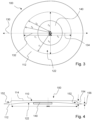
- the damper device 100 is shown in isolation, in plan view, in Figure 3 .
- the damper device 100 is for providing damping of the primary structure 10.
- the primary structure 10 is a component.
- the component may be a duct 10.
- the duct 10 may be a duct for gas or liquid.
- the primary structure 10 may be any structure which it is desired to damp, for example any structure or component which exhibits or undergoes vibration.
- the damper device 100 may be provided separately to, or in absence of, the primary structure 10.
- the damper device 100 may be manufactured separately to the primary structure 10.
- the primary structure 10 may be an existing structure which it is desired to damp, and the damper device 100 may be subsequently provided, or retrofitted, to or at the primary structure 10 to provide damping thereof.
- the damper device 100 may be formed in the primary structure 10.
- the damper device 100 may be embedded in the primary structure 10, for example in a surface of the primary structure 10.
- the damper device 100 comprises a body 110.
- the body 110 comprises a first surface 112 and a second surface 114.
- the first surface 112 is a lower surface and the second surface 114 is an upper surface.
- An acoustic black hole (ABH) 122 is provided in the body 110 at the first surface 112 of the body 110.
- the ABH 122 may be referred to as a "first ABH 122".
- the first ABH 122 being provided in the body 110 at the first surface 112 of the body 110 may be described as the first ABH 122 being "embedded” in the first surface 112.
- Prior art devices may incorporate ABH structures which are provided on pedestals, supports, or stands.
- the first ABH 122 of the present invention is provided in the body 110. This is advantageous in providing a low-profile construction, thus enabling space saving, or application in situations and environments where space is limited. This might also make the ABH 122 and/or device more robust.
- a key feature of the present invention is the provision of an asymmetric first ABH 122.
- prior art ABHs include a variation in characteristic which is symmetric (e.g., constant, consistent, or uniform) in the ABH
- the present invention includes different characteristic variations.
- the symmetric variation for example, a thickness tapering over a constant length
- the symmetric variation has the result of the ABH effect being suited to control only a limited frequency bandwidth of vibration.
- Other frequencies of vibration, or vibrational modes, outside of the bandwidth of control of the ABH will not be damped by the ABH.
- prior art ABHs may not be suited to provide structural damping of certain vibrational modes within the bandwidth of control, due to their symmetric variation in characteristic.
- the first ABH 122 has an asymmetric variation in characteristic.
- the asymmetric variation in characteristic has multiple functions, and benefits, which in some cases may depend on the tuning (e.g., the design of the variation in characteristic, which may include shaping or material choice) of the first ABH 122.
- the asymmetric variation in characteristic of the first ABH 122 results in the first ABH 122 being configured to control a plurality of vibrational modes. This may mean that the first ABH 122 is configured to control more vibrational modes that a symmetric ABH of the prior art.
- the first ABH 122 can "couple" to the primary structure more efficiently over a bandwidth compared with a prior art ABH which is configured to control the same bandwidth.
- the first ABH 122 enables the control of more vibrational modes than the prior art ABH. That is, within the same bandwidth of control (i.e., where the first ABH 122 and prior art ABH are tuned to control the same range of frequencies), the first ABH 122 will be able to control more vibrational modes than a prior art ABH, and thus provide a higher level of structural damping.
- the asymmetric variation in characteristic of the first ABH 122 can broaden the frequency response of the first ABH 122. This may be in addition to, or alternative to, improving the damping performance within the same bandwidth, as described above.
- the asymmetric variation in characteristic of the first ABH 122 results in the first ABH 122 being configured to control a plurality of vibrational modes. Said plurality of vibrational modes may have a broader bandwidth than prior art symmetric ABHs and thus the asymmetric variation in characteristic of the first ABH 122 is able to broaden the frequency response.
- the first ABH 122 provides a wider band of control than a prior art symmetric ABH.
- the first ABH 122 comprises different characteristic variations, e.g., a plurality of different characteristic variations.
- a first variation in characteristic and a second variation in characteristic which are different variations (for example, different lengths over which the ABH taper occurs).
- a "matching" of a first vibration with the first variation in characteristic will provide damping of the first vibration
- a "matching" of a second vibration with the second variation in characteristic will provide damping of the second vibration.
- the first vibration and second vibration may be of a different frequency
- the invention provides for control of the different frequencies of vibration using a single first ABH 122, as a result of the asymmetry of the first ABH 122.
- the invention provides for multiple control bands for damping vibration, which may improve damping performance over prior art ABHs configured to operate across the same bandwidth and/or provide a broader bandwidth of control of frequencies of vibration of a primary structure.
- Asymmetry may be defined as an ABH having a different first variation in characteristic of the first ABH 122 and second variation in characteristic of the first ABH 122.
- Each of the first and second variation may be known as an "ABH variation", as it is due to the variation that the ABH effect occurs.
- the variation in characteristic may be a thickness taper, or a variation in material or material property (e.g., rigidity and/or density).
- the ABH variation may be along a line of maximal variation.
- an example of the first ABH 122 comprises a first axis 130.
- the first axis 130 is a major axis of the first ABH 122.
- the first ABH 122 is symmetrical either side of the first axis 130.
- the first variation is a tapering of the thickness of the first ABH 122 along a first length r 1 .
- the first direction 132 is in, or is parallel to, the first axis 130.
- a second direction 134 there is a second variation.
- the second direction 134 is in, or is parallel to, the first axis 130.
- the second direction 134 is opposite to the first direction 132.
- the second variation is a tapering of the thickness of the first ABH 122 along a second length r 2 .
- the first length r 1 and second length r 2 are different.
- the first length r 1 is greater than the second length r 2 .
- the first ABH 122 is asymmetric by virtue of the different variations in characteristic. Asymmetry of the first ABH 122 is highly advantageous in providing an ABH which is able to control, or damp, a broad(er) band of frequencies of vibration, and/or control a greater number of vibrational frequencies.
- the first variation is a tapering of the thickness of the first ABH 122 along a first length r 1 , from a first thickness (indicated at 142) to a second thickness (indicated at 144), and the second variation is a tapering of the thickness of the first ABH 122 along a second length r 2 , from a first thickness (indicated at 146) to a second thickness (indicated at 144).
- the first variation may be from a first characteristic to a second characteristic, along a line of a first length r 1
- the second variation may be from a first (or third) characteristic to a second (or fourth) characteristic along a line of a second length r 2
- the first length r 1 and second length r 2 are different lengths.
- the first length r 1 and second length r 2 may be radii of the first ABH 122.
- the third variation is a tapering of the thickness of the first ABH 122 along a third length r 3 .
- the third length r 3 is the same as the second length r 2 .
- the second length r 2 and third length r 3 are the same radii of the first ABH 122.
- perpendicular to the first axis 130 there is a fourth variation.
- the fourth variation is in an opposite direction to the third variation.
- the fourth variation is a tapering of the thickness of the first ABH 122 along a fourth length r 4 .
- the fourth length r 4 is the same as the second length r 2 , and also the same as the third length r 3 . That is, in this example, the second length r 2 , third length r 3 and fourth length r 4 are the same radii of the first ABH 122.
- the asymmetry is thus provided by the first variation along the first length r 1 , and also by the varying lengths (e.g., radii) in the segment of the first ABH 122 between the first axis 130 and the perpendicular.
- fifth, sixth and seventh lengths r 5 , r 6 , r 7 are all different lengths, and thus provide asymmetry to control different vibrational frequencies.
- the first ABH 122 may be tuned such that the third length r 3 and fourth length r 4 are different, which would also provide the advantage of improved broadband performance of the first ABH 122.
- asymmetry of the ABH may also be provided in more complex shapes of the first ABH 122.
- the first ABH 122 may have, for example, a star-shaped profile, wherein the first ABH 122 tapers from outer edges of the star to the centre of the star.
- the first ABH 122 has a first variation in characteristic (for example, from a centre of the star to a point thereof) and a second variation in characteristic (for example, from a centre of the star to an inner vertex formed by intersecting edges of the star). It will be appreciated that in such a shape the first variation in characteristic and second variation in characteristic are different, as a result of the aforementioned variations occurring over different lengths. In this way, the frequency response of the first ABH 122 is broadened.
- the first ABH 122 may be asymmetric, which may mean that the radii (e.g., distance from a centre point to a periphery of the first ABH 122) or maximum extents of the first ABH 122 are different in one or more different directions. That is, a first variation in characteristic may be from a centre point to a first point at the periphery of the first ABH 122, and a second variation in characteristic may be from the centre point to a second point at the periphery of the first ABH 122, and the first and second variation in characteristic are in different directions and are different variations, thereby to provide asymmetry.
- a first variation in characteristic may be from a centre point to a first point at the periphery of the first ABH 122
- a second variation in characteristic may be from the centre point to a second point at the periphery of the first ABH 122
- the first and second variation in characteristic are in different directions and are different variations, thereby to provide asymmetry.
- each variation in characteristic is such that the ABH effect is realised due to the variation in characteristic. That is, the variation in characteristic is not merely a change in spatial property, material and/or material property, but is instead a variation suitable for exhibiting the ABH effect, as will be appreciated by those skilled in the art.
- ABH tapers which may comprise a constant variation in characteristic, such as ABHs provided at a terminal end of a beam having a constant ABH length (for example, as shown in Figure 1 ), or such as a conventional circular ABH having a constant radius (i.e., constant ABH taper length).
- ABHs provided at a terminal end of a beam having a constant ABH length (for example, as shown in Figure 1 ), or such as a conventional circular ABH having a constant radius (i.e., constant ABH taper length).
- the damper device 100 may be formed in multiple parts, which may be subsequently connected or attached.
- the damper device 100 may be formed in two halves (which may include a first half comprising a portion of the first ABH 122 and body 110 and a second half comprising a portion of the first ABH 122 and body 110). This may simplify construction of the asymmetric first ABH 122.
- the first surface 112 of the body 110 may be adapted to contact the upper surface 12 of the primary structure 10.
- the first surface 112 of the body 110 is adapted to contact the upper surface 12 of the component 10 in a facing manner. That is, the first surface 112 does not extend laterally from the component 10, as in conventional add-on damper devices for beams or the like. Instead, the first surface 112 of the body 110 and upper surface 12 component 10 are arranged, or provided, such that they face one another.
- the facing manner may alternatively be described as a "layered" construction, or one where the first surface 112 is provided to extend across a surface (e.g., the upper surface 12) of a primary structure 10, or the first surface 112 "opposing" the primary structure 10.
- first ABH 122 being provided in the body 110 at the first surface 112, and the first surface 112 of the body 110 being adapted to contact the upper surface 12 of the primary structure 10 in a facing manner, numerous advantages are realised. Vibrational damping of the component 10 is provided by the body 110 comprising the first ABH 122 being in contact with the primary structure 10. Furthermore, the thinnest region of the first ABH 122 is provided displaced over (e.g., above, as in this exemplary embodiment) the upper surface 12 of the primary structure 10. The risk of damage to the first ABH 122 is thereby reduced, as the thin region of the ABH does not extend laterally/project freely from the edge of the primary structure 10, as in conventional add-on damper devices. Additionally, the first ABH 122 is not required to extend laterally from the primary structure 10, which has advantages in space-saving, in that the total footprint of the primary structure 10 and damper device 100 is not increased beyond that of the primary structure 10 itself.
- the body 110 is in contact with the primary structure 10 at the first surface 112. Flexural waves propagate from the primary structure 10 to the damper device 100 at the point of contact therebetween.
- the damper device 100 may be described as being coupled, attached or connected to the primary structure 10. Coupling may be by application of adhesive or other coupling/attachment means. Alternatively, the damper device 100 may be integrally formed with the primary structure, e.g., one-piece formed. Additive layer manufacturing may be used as a suitable construction technique.
- the first ABH 122 is adapted to contact the upper surface 12 of the primary structure 10.
- an outermost region (indicated at 124) of the first ABH 122 is adapted to contact the upper surface 12 of the primary structure 10.
- the outermost region 124 is in proximity of the region of first characteristic of the ABH 122.
- the ABH 122 contacts the primary structure 10 at a point or region having relatively greater strength compared with other points or regions of the first ABH 122, for example regions of the first ABH 122 having the second characteristic.
- the primary structure 10 can provide cooperative structural support to the first ABH 122.
- the body 110 is planar. In this way, the damper device 100 may have a low profile, such that it can be employed in limited space situations.
- the body 110 may be a plate or have the form of a plate.
- the first surface 112 is a first surface of the plate
- the second surface 114 is a second surface of the plate. In this way, the damper device 100 may have a low profile.
- the damper device 100 is thus highly advantageous in that it can be employed in situations where space is limited, such as in a duct or vent system. Furthermore, the risk of damage to the damper device 100 is reduced due to the low-profile of the plate form of the body 110.
- At least a part of the first surface 112 and/or ABH 122 formed in the upper surface 112 does not contact the primary structure 10. That is, the first surface 112 may be arranged to contact the upper surface 12 of the primary structure 10 such that a gap is formed between the ABH 122 and the upper surface 12 of the primary structure 10.
- this may improve performance of the ABH 122, as the ABH effect can be exhibited in an unimpaired manner.
- this may advantageously facilitate inclusion of damping material (or the existence of air, which may act to provide damping) in the gap or cavity thereby formed.
- the first surface 112 is arranged to contact the upper surface 12 of the primary structure 10 such that a cavity 150 is formed between the ABH 122 and the upper surface 12 of the primary structure 10.
- a cavity 150 can improve performance of the damper device 100, as air within the cavity 150, or between the ABH 122 and the upper surface 12 of the primary structure 10, provides a level of damping. Furthermore, deterioration of the ABH 122 is inhibited/prevented due to protection offered by the cavity 150.
- the cavity 150 may be partially, or substantially, enclosed. In this way, structural strength of the ABH 122 is improved.
- a partially, or substantially, enclosed cavity 150 may mean that the cavity 150 is only open at side regions.
- the cavity 150 is completely enclosed, or sealed.
- the structural strength of the ABH 122 is improved.
- a volume of air is retained within the cavity 150.
- This is advantageous in improving damping performance of the damper device 100, as the air retained within the cavity 150 provides a level of damping.
- the aforementioned problem of a broadband frequency response of the first ABH 122 leading to a reduction in the level of attenuation can be mitigated, as the damping performance is improved by the enclosed cavity 150. That is, the asymmetry of the first ABH 122 and provision of the enclosed cavity 150 provides a synergistic technical effect, and advantage. Additionally, ingress of external air or contaminants are prevented from entering the cavity 150 when it is enclosed, thus preventing degradation of the damper device 100 and the materials thereof over time. The lifetime of the damper device 100 is thus increased. An improved broadband damper device 100 is thus provided.
- a damping material 140 may be provided on the first ABH 122.
- the damping material 140 is provided on at least a region of the first ABH 122.
- the damping material 140 is provided on the surface of the first ABH 122.
- the damping material 140 may be provided on the tapering surface of the first ABH 122.
- the damping material 140 may be provided on the whole of the first ABH 122.
- the damping material 140 may be a viscoelastic layer.
- the damping material 140 may be a thin layer.
- the damping material 140 provides an additional damping effect in the first ABH 122, which may reduce reflection of an incident wave.
- the first ABH 122 is in the form of a concave elliptical recess in the first surface 112. In this way, different variations in characteristic are obtained by thickness variation. It will be appreciated from the present disclosure that the first ABH 122 may be in the form of a concave circular recess, where the different variation in characteristic may be provided by variation in material or material property. That is, the variation need not be a thickness variation, and the asymmetry may be achieved by material or material property variation or tapering.
- An elliptical recess may be known as an oval recess.
- the body 110 may have a circular or elliptical form. Such a construction may be advantageous in reducing weight of the damper device 100. Furthermore, such forms may be particularly suited to provision of a circular or elliptical (e.g., oval) first ABH 122 in the body 110 at the first surface 112 of the body 110.
- a circular or elliptical e.g., oval
- the damper device 100 further comprises a second ABH 152.
- the second ABH 152 is provided at the second surface 114 of the body 110. That is, the second ABH 152 is provided at the upper surface 114 of the body 110.
- the second ABH 152 provides further damping, in addition to that of the first ABH 122, such that performance of the damper device 100 is improved. That is, a combined damping effect is realised. Furthermore, the weight of the body 110 is reduced by provision of the second ABH 152. Additionally, the broadband frequency response of vibration control may be improved, as the second ABH 152 may have a variation in characteristic (e.g., a taper) which is configured or designed to control a different frequency, or frequency range, of vibration to the first ABH 122. In this way, more frequencies of vibration of a primary structure 20 may be controlled.
- a variation in characteristic e.g., a taper
- the second ABH 152 comprises a tapering from a first characteristic to a second characteristic.
- the second ABH 152 is configured to exhibit the ABH effect.
- the taper is a thickness taper, and as such the characteristic is a thickness.
- the first characteristic is indicated as first thickness 154
- the second characteristic is indicated as second thickness 156.
- the first characteristic and second characteristic of the second ABH 152 may be referred to as “third characteristic” and “fourth characteristic”, which may clarify and distinguish said characteristics from those of the first ABH 122.
- the characteristic of the second ABH 152 may similarly be a thickness, shape, material and/or material property, for example rigidity and/or density.
- the second ABH 152 is provided proximal to an edge of the body 110. This may lead to a simplified construction of the damper device 100, as it is not necessary to fully embed the second ABH 152 in the body 110.
- the second ABH 152 tapers in the second direction 138 to the edge of the body 110. As will be understood from considering the damper device 100 in plan and/or side view, the edge of the body 110 is the outermost edge (the circumference) of the circular body 110.
- the second ABH 152 has an annular form. That is, the second ABH 152 extends fully around the circumference of the circular body 110. In this way, the second ABH 152 may be adapted to damp waves propagating in all directions through the body 110.
- the second ABH 152 is vertically disposed above the region, or point, of contact of the first surface 112 with the primary structure 10. As such, the second ABH 152 is proximal to the point or region at which flexural waves propagate from the primary structure 10 to the damper device 100.
- each ABH may be suited to damping of different frequencies of vibrations.
- the structurally damped structure 1000 comprises a primary structure 10.
- the structurally damped structure 1000 further comprises a damper device 100 to provide damping of the primary structure 10.
- the damper device 100 may incorporate any of the features herein described.
- a structurally damped structure 1000 is provided in which vibrations of the primary structure 10 are damped (e.g., controlled) by the damper device 100.
- the vehicle 600 comprises a damper device 100 and/or a structurally damped structure 1000, according to any of the embodiments described herein.
- the vehicle 600 may be a land-based vehicle, watercraft, or aircraft.
- the vehicle, or a component thereof, may comprise, or be, the primary structure.
- the structure 700 comprises a damper device 100 and/or a structurally damped structure 1000, according to any of the embodiments described herein.
- the structure 700 may be a building, infrastructure, construction, or the like.
- the structure, or a component thereof, may comprise, or be, the primary structure.
- Step S810 comprises providing a damper device comprising: a body comprising a first surface and a second surface; and a first acoustic black hole, ABH, provided in the body at the first surface of the body, the first ABH having an asymmetric variation in characteristic.
- Step S820 comprises damping the primary structure using the damper device.
Landscapes
- Physics & Mathematics (AREA)
- Engineering & Computer Science (AREA)
- Acoustics & Sound (AREA)
- Multimedia (AREA)
- Vibration Prevention Devices (AREA)
Abstract
According to the present disclosure, there is provided a damper device (100) for providing damping of a primary structure (10) comprising: a body (110) comprising a first surface (112) and a second surface (114); and a first acoustic black hole, ABH (122), provided in the body at the first surface of the body, the first ABH having an asymmetric variation in characteristic.
Description
- The present invention relates to a damper device, a structurally damped structure, and method of damping a primary structure.
- In product design, it is often necessary to design a product that is both lightweight and a low noise structure. However, this results in a conflict between reducing the weight and increasing the sound radiation from the structure. It is known to use a structure referred to as an acoustic black hole (ABH) to provide structural damping.
- An acoustic black hole was originally described by Mironov in 1988 (M.A. Mironov. Propagation of a flexural wave in a plate whose thickness decreases smoothly to zero in a finite interval. Soviet Physics: Acoustics, 34(3):318-319, 1988). The acoustic black hole effect is typically achieved by introducing a power law taper into a beam or plate that changes the thickness over a set distance. This change in thickness profile causes the flexural waves propagating along the direction of the ABH to decrease in wave speed. In the theoretical limit, there is no reflection of the waves from the ABH. The ABH effect can also be achieved using other gradient functions, including a power-cosine curve, for example.
-
Figure 1 shows an example of anABH 1 on abeam 2. The ABH 1 is provided with a layer of dampingmaterial 3. The flexural wave speed cf (x), decreases as the taper height decreases as:
- From
Equation 1 it can be seen that if the tip of the ABH reduces to zero thickness, i.e. h(x)=0, then the flexural wave speed at the tip will be c f (x)=0. In this ideal, theoretical case, the incident wave will not be reflected from the end of the tapered beam and will therefore, be effectively attenuated. - In this respect, acoustic black holes are known in the art. For example, `Higher-order WKB analysis of reflection from tapered elastic wedges' Journal of Sound and Vibration 449 (2019) 368-388 (Angelis Karlos, Stephen J. Elliot, Jordan Cheer), the contents of which are incorporated herein, provides examples of different types of 'one-dimensional' acoustic black holes. The thickness variations, of these acoustic black holes, are according to the expressions provided in Table 1 below:
Table 1 Thickness profile type Thickness variation Length of ideal wedge Decay parameter Power-law 

- Exponential 
∞ 
Power-cosine 

- Gaussian 
∞ 
Compound power-law 

- - `x' is the distance, in the length direction, from the upstream end of the acoustic black hole (i.e. at the start of the taper);
- 'x1' is the length of the acoustic black hole;
- 'h' is the thickness of the acoustic black hole (at position (x));
- `h0' is the thickness of the acoustic black hole at the upstream end of the acoustic black hole (i.e. at position (x = 0));
- `h1' is the thickness of the acoustic black hole at the downstream end of the acoustic black hole (i.e. at position (x = x1));
- 'n' is power coefficient of the shape function (which must be greater or equal to 2).
- These parameters are illustrated in
Figure 1 . - It is known in the art to provide damper devices comprising ABHs as an add-on for a beam. These add-ons are attached to the beam at an edge of the beam. Whilst advantageous in providing damping, the ABH is susceptible to damage. As examples, damage may be caused by contact with surrounding components, or by stress-related weaking over time and operation. Additionally, the ABH may degrade due to exposure to air or contaminants. Furthermore, damping material is typically provided, which, whilst improving damping performance of the ABH, it would be desirable to further improve damping performance where possible. To widen the potential applications of ABHs, it is desirable to overcome these limitations.
- Furthermore, prior art ABHs typically have a limited frequency response. That is, prior art ABHs are typically configured to control vibration of a particular frequency, or vibration within a narrow frequency band. It is desirable to improve control over a range of frequencies.
- It is one aim of the present invention, amongst others, to provide an improved damper device and/or address one or more of the problems discussed above, or discussed elsewhere, or to at least provide an alternative damper device.
- According to a first aspect of the present invention, there is provided a damper device for providing damping of a primary structure comprising: a body comprising a first surface and a second surface; and a first acoustic black hole, ABH, provided in the body at the first surface of the body, the first ABH having an asymmetric variation in characteristic.
- In one example, the first ABH comprises: in a first axis, a first variation in characteristic, in a first direction; and in the first axis, a second variation in characteristic, in a second direction opposite to the first direction, wherein the first variation and second variation are different.
- In one example, the asymmetric variation in characteristic is such that the first ABH is configured to control a plurality of vibrational modes.
- In one example, the asymmetric variation in characteristic is provided thereby to broaden the frequency response, or bandwidth, of the first ABH.
- In one example, the asymmetric variation in characteristic is provided thereby to increase a level of coupling with vibration of the primary structure.
- In one example, the asymmetric variation in characteristic controls or defines (for use) a plurality of vibrational control modes.
- In one example, the first surface of the body is adapted to contact, in a facing manner, a surface of the primary structure.
- In one example, the body is planar.
- In one example, the body is a plate. In one example, the first surface is a first surface of the plate. In one example, the second surface is a second surface of the plate.
- In one example, the body is adapted to contact the surface of the primary structure such that a cavity is formed between the first ABH and the surface of the primary structure.
- In one example, the cavity is enclosed.
- In one example, the first ABH is in the form of a concave elliptical recess in the first surface.
- In one example, the body has a circular or elliptical form.
- In one example, the damper device further comprises a second ABH provided at the second surface of the body.
- In one example, the second ABH is provided proximal to an edge of the body.
- In one example, the second ABH has an annular form.
- In one example, the second ABH comprises in a first axis, in a second direction opposite to the first direction, a tapering from a first characteristic to a second characteristic.
- In one example, the characteristic is one or more of: a spatial property, a material, and/or a material property. In one example, the spatial property is a thickness and/or shape. In one example, the material property is rigidity and/or density.
- In one example, a damping material is provided on the first ABH.
- According to a second aspect of the present invention, there is provided a structurally damped structure comprising: a primary structure; and the damper device according to the first aspect of the present invention to provide damping of the primary structure.
- According to a third aspect of the present invention, there is provided a method of damping a primary structure comprising: providing a damper device comprising: a body comprising a first surface and a second surface; and a first acoustic black hole, ABH, provided in the body at the first surface of the body, the first ABH having an asymmetric variation in characteristic; and damping the primary structure using the damper device.
- In one example, the first ABH comprises: in a first axis, a first variation in characteristic, in a first direction; and in the first axis, a second variation in characteristic, in a second direction opposite to the first direction, wherein the first variation and second variation are different.
- In one example, the asymmetric variation in characteristic is such that the first ABH is configured to control a plurality of vibrational modes.
- In one example, the asymmetric variation in characteristic is provided thereby to broaden the frequency response, or bandwidth, of the first ABH.
- In one example, the asymmetric variation in characteristic is provided thereby to increase a level of coupling with vibration of the primary structure.
- In one example, the asymmetric variation in characteristic controls or defines (for use) a plurality of vibrational control modes.
- Features of any one aspect may be combined with features of any other aspect, as desired or as appropriate. In particular, features of the damper device according to the first aspect and/or structurally damped structure according to the second aspect may be combined with features of the method according to the third aspect.
- Embodiments of the invention will now be described by way of example only with reference to the figures, in which:
-
Figure 1 shows an acoustic black hole on a beam according to the prior art; -
Figure 2 shows a side cross sectional view through a damper device and primary structure; -
Figure 3 shows a plan view of the damper device ofFigure 2 ; -
Figure 4 shows a side cross sectional view through a damper device; -
Figure 5 shows a schematic of a structurally damped structure comprising a damper device and primary structure; -
Figure 6 shows a vehicle; -
Figure 7 shows a structure; and -
Figure 8 shows general methodology principles. - In the description which follows, acoustic black holes, damper devices, structurally damped structures, and methods, are described.
- The term "acoustic black hole", or "ABH", is used to refer to an element, member, or structure, which, in use, exhibits the acoustic black hole effect.
- In examples of the invention described herein, acoustic black holes comprise variations in, or of, characteristic. Such variations in, or of, characteristic are in order to provide an arrangement to exhibit the ABH effect, in use. The variation in characteristic may be regions of taper. In examples shown and described herein, the taper is a thickness taper. That is, the thickness of the acoustic black hole tapers (i.e., reduces or diminishes in thickness in a direction and along a line toward a point, line or region). Additionally, or alternatively, tapering may be in shape. A thickness or shape may be referred to generally as a "spatial property". Conventional ABHs incorporate tapers in thickness, from a first thickness to a second thickness. The first thickness is typically a non-zero thickness. The second thickness is, in the ideal case, a zero thickness. A thickness or shape taper may be advantageous in that it may be simpler to manufacture than, for example, a taper in material and/or material property.
- However, in contrast to a thickness taper, in other examples of the present invention, the variation could also be a "functional taper" or a "functional grading". That is, the tapering could be a tapering function of the acoustic black hole, rather than a tapering thickness. For example, the tapering may be a tapering of material and/or material property. The material property may be, for example, density and/or rigidity. This may be achieved by use of additive layer manufacturing (e.g. 3D printing) to form an acoustic black hole having a tapering, graded, or varying, material property. A tapering in material and/or material property may be advantageous in that thin ABH regions need not be provided, which may improve the structural strength, and operational lifetime, of the ABH.
- In this way, it is appropriate to refer to ABH tapers as a variation in a "characteristic". Variation, or tapering, may be from a "first characteristic" to a "second characteristic". A similar or identical effect to a thickness tapering may be achieved by a variation, or tapering, in material and/or material property. For example, a tapering from a region of high rigidity to a region of low rigidity may provide a reduction of the flexural wave speed to c f (x)=0, as described above, thereby to provide the ABH effect.
- The term "damper device" is used to refer to an arrangement, assembly or kit comprising a body and an acoustic black hole. The damper device is adapted to provide structural damping to a structure to which the damper device is connected, coupled, or otherwise provided on or at.
- The term "structurally damped structure" is used to refer to a structure, arrangement, assembly or kit comprising a damper device and a primary structure.
- The term "primary structure" is used to refer to a structure that the damper device is arranged to provide structural damping to. The primary structure is a structure that, in use, has a vibration applied to it. The primary structure may be a structure that is vibrated, directly or indirectly, by a source of vibration (e.g., an engine, fluid flow, etc.).
- The damper device may be formed in or on the primary structure. For example, the damper device may be integral to the primary structure. Alternatively, or additionally, the damper device may be coupled to the primary structure. That is, the damper device may be manufactured separately and coupled, or connected, to the primary structure.
- A side cross section view of a
primary structure 10 and adamper device 100 is shown inFigure 2 . Thedamper device 100 is shown in isolation, in plan view, inFigure 3 . - The
damper device 100 is for providing damping of theprimary structure 10. In an example, theprimary structure 10 is a component. The component may be aduct 10. For example, theduct 10 may be a duct for gas or liquid. Nevertheless, it will be appreciated that theprimary structure 10 may be any structure which it is desired to damp, for example any structure or component which exhibits or undergoes vibration. - The
damper device 100 may be provided separately to, or in absence of, theprimary structure 10. Thedamper device 100 may be manufactured separately to theprimary structure 10. Theprimary structure 10 may be an existing structure which it is desired to damp, and thedamper device 100 may be subsequently provided, or retrofitted, to or at theprimary structure 10 to provide damping thereof. - Furthermore, the
damper device 100 may be formed in theprimary structure 10. In an example, thedamper device 100 may be embedded in theprimary structure 10, for example in a surface of theprimary structure 10. - The
damper device 100 comprises abody 110. Thebody 110 comprises afirst surface 112 and asecond surface 114. In this exemplary embodiment, thefirst surface 112 is a lower surface and thesecond surface 114 is an upper surface. - An acoustic black hole (ABH) 122 is provided in the
body 110 at thefirst surface 112 of thebody 110. TheABH 122 may be referred to as a "first ABH 122". Thefirst ABH 122 being provided in thebody 110 at thefirst surface 112 of thebody 110 may be described as thefirst ABH 122 being "embedded" in thefirst surface 112. Prior art devices may incorporate ABH structures which are provided on pedestals, supports, or stands. However, in contrast to the prior art, thefirst ABH 122 of the present invention is provided in thebody 110. This is advantageous in providing a low-profile construction, thus enabling space saving, or application in situations and environments where space is limited. This might also make theABH 122 and/or device more robust. - A key feature of the present invention is the provision of an asymmetric
first ABH 122. Whilst prior art ABHs include a variation in characteristic which is symmetric (e.g., constant, consistent, or uniform) in the ABH, the present invention includes different characteristic variations. In the prior art, the symmetric variation (for example, a thickness tapering over a constant length) has the result of the ABH effect being suited to control only a limited frequency bandwidth of vibration. Other frequencies of vibration, or vibrational modes, outside of the bandwidth of control of the ABH will not be damped by the ABH. Additionally, prior art ABHs may not be suited to provide structural damping of certain vibrational modes within the bandwidth of control, due to their symmetric variation in characteristic. - In contrast, the
first ABH 122 has an asymmetric variation in characteristic. The asymmetric variation in characteristic has multiple functions, and benefits, which in some cases may depend on the tuning (e.g., the design of the variation in characteristic, which may include shaping or material choice) of thefirst ABH 122. The asymmetric variation in characteristic of thefirst ABH 122 results in thefirst ABH 122 being configured to control a plurality of vibrational modes. This may mean that thefirst ABH 122 is configured to control more vibrational modes that a symmetric ABH of the prior art. As a result, thefirst ABH 122 can "couple" to the primary structure more efficiently over a bandwidth compared with a prior art ABH which is configured to control the same bandwidth. This is because asymmetric variation in characteristic of thefirst ABH 122 enables the control of more vibrational modes than the prior art ABH. That is, within the same bandwidth of control (i.e., where thefirst ABH 122 and prior art ABH are tuned to control the same range of frequencies), thefirst ABH 122 will be able to control more vibrational modes than a prior art ABH, and thus provide a higher level of structural damping. - Furthermore, in some examples, the asymmetric variation in characteristic of the
first ABH 122 can broaden the frequency response of thefirst ABH 122. This may be in addition to, or alternative to, improving the damping performance within the same bandwidth, as described above. As above, the asymmetric variation in characteristic of thefirst ABH 122 results in thefirst ABH 122 being configured to control a plurality of vibrational modes. Said plurality of vibrational modes may have a broader bandwidth than prior art symmetric ABHs and thus the asymmetric variation in characteristic of thefirst ABH 122 is able to broaden the frequency response. In other words, thefirst ABH 122 provides a wider band of control than a prior art symmetric ABH. - In other words, in the present invention, by asymmetric variation the
first ABH 122 comprises different characteristic variations, e.g., a plurality of different characteristic variations. An example of this is a first variation in characteristic and a second variation in characteristic, which are different variations (for example, different lengths over which the ABH taper occurs). In this way, a "matching" of a first vibration with the first variation in characteristic will provide damping of the first vibration, and a "matching" of a second vibration with the second variation in characteristic will provide damping of the second vibration. That is, the first vibration and second vibration may be of a different frequency, and the invention provides for control of the different frequencies of vibration using a singlefirst ABH 122, as a result of the asymmetry of thefirst ABH 122. Overall, the invention provides for multiple control bands for damping vibration, which may improve damping performance over prior art ABHs configured to operate across the same bandwidth and/or provide a broader bandwidth of control of frequencies of vibration of a primary structure. - Asymmetry may be defined as an ABH having a different first variation in characteristic of the
first ABH 122 and second variation in characteristic of thefirst ABH 122. Each of the first and second variation may be known as an "ABH variation", as it is due to the variation that the ABH effect occurs. As above, the variation in characteristic may be a thickness taper, or a variation in material or material property (e.g., rigidity and/or density). The ABH variation may be along a line of maximal variation. - In respect of this, an example of the
first ABH 122 comprises afirst axis 130. Thefirst axis 130 is a major axis of thefirst ABH 122. In this example, thefirst ABH 122 is symmetrical either side of thefirst axis 130. - Along the
first axis 130, in afirst direction 132, there is a first variation. In this example, the first variation is a tapering of the thickness of thefirst ABH 122 along a first length r1. Thefirst direction 132 is in, or is parallel to, thefirst axis 130. Furthermore, along thefirst axis 130, in asecond direction 134, there is a second variation. Thesecond direction 134 is in, or is parallel to, thefirst axis 130. Thesecond direction 134 is opposite to thefirst direction 132. In this example, the second variation is a tapering of the thickness of thefirst ABH 122 along a second length r2. The first length r1 and second length r2 are different. In this example, the first length r1 is greater than the second length r2. In this way, thefirst ABH 122 is asymmetric by virtue of the different variations in characteristic. Asymmetry of thefirst ABH 122 is highly advantageous in providing an ABH which is able to control, or damp, a broad(er) band of frequencies of vibration, and/or control a greater number of vibrational frequencies. - As above, in this example, the first variation is a tapering of the thickness of the
first ABH 122 along a first length r1, from a first thickness (indicated at 142) to a second thickness (indicated at 144), and the second variation is a tapering of the thickness of thefirst ABH 122 along a second length r2, from a first thickness (indicated at 146) to a second thickness (indicated at 144). - It has been found that the greater the difference in variations in characteristic of the
first ABH 122, the broader band frequency response will be achievable using thefirst ABH 122. However, this may result in a reduced level of attenuation of the vibration. It may thus be advantageous to configure thefirst ABH 122 to control specific vibration frequencies, or a band of vibration frequencies, at an attenuation level appropriate for the use case. - For avoidance of doubt, and as described above, the first variation may be from a first characteristic to a second characteristic, along a line of a first length r1, and the second variation may be from a first (or third) characteristic to a second (or fourth) characteristic along a line of a second length r2. The first length r1 and second length r2 are different lengths. The first length r1 and second length r2 may be radii of the
first ABH 122. - Also shown in
Figure 3 , perpendicular to thefirst axis 130, there is a third variation. In this example, the third variation is a tapering of the thickness of thefirst ABH 122 along a third length r3. The third length r3 is the same as the second length r2. In this example, the second length r2 and third length r3 are the same radii of thefirst ABH 122. Furthermore, perpendicular to thefirst axis 130, there is a fourth variation. The fourth variation is in an opposite direction to the third variation. In this example, the fourth variation is a tapering of the thickness of thefirst ABH 122 along a fourth length r4. The fourth length r4 is the same as the second length r2, and also the same as the third length r3. That is, in this example, the second length r2, third length r3 and fourth length r4 are the same radii of thefirst ABH 122. The asymmetry is thus provided by the first variation along the first length r1, and also by the varying lengths (e.g., radii) in the segment of thefirst ABH 122 between thefirst axis 130 and the perpendicular. For example, fifth, sixth and seventh lengths r5, r6, r7 are all different lengths, and thus provide asymmetry to control different vibrational frequencies. Similarly, thefirst ABH 122 may be tuned such that the third length r3 and fourth length r4 are different, which would also provide the advantage of improved broadband performance of thefirst ABH 122. - Furthermore, asymmetry of the ABH may also be provided in more complex shapes of the
first ABH 122. For example, thefirst ABH 122 may have, for example, a star-shaped profile, wherein thefirst ABH 122 tapers from outer edges of the star to the centre of the star. In such examples, and consistent with the above, thefirst ABH 122 has a first variation in characteristic (for example, from a centre of the star to a point thereof) and a second variation in characteristic (for example, from a centre of the star to an inner vertex formed by intersecting edges of the star). It will be appreciated that in such a shape the first variation in characteristic and second variation in characteristic are different, as a result of the aforementioned variations occurring over different lengths. In this way, the frequency response of thefirst ABH 122 is broadened. - In general terms, the
first ABH 122, or shape or profile thereof, may be asymmetric, which may mean that the radii (e.g., distance from a centre point to a periphery of the first ABH 122) or maximum extents of thefirst ABH 122 are different in one or more different directions. That is, a first variation in characteristic may be from a centre point to a first point at the periphery of thefirst ABH 122, and a second variation in characteristic may be from the centre point to a second point at the periphery of thefirst ABH 122, and the first and second variation in characteristic are in different directions and are different variations, thereby to provide asymmetry. In some situations, it is not necessary for the first variation in characteristic and second variation in characteristic to be along the same axis (e.g., along the first axis 130). Applicable to the above, each variation in characteristic is such that the ABH effect is realised due to the variation in characteristic. That is, the variation in characteristic is not merely a change in spatial property, material and/or material property, but is instead a variation suitable for exhibiting the ABH effect, as will be appreciated by those skilled in the art. It will be appreciated that the above is in contrast to conventional ABH tapers, which may comprise a constant variation in characteristic, such as ABHs provided at a terminal end of a beam having a constant ABH length (for example, as shown inFigure 1 ), or such as a conventional circular ABH having a constant radius (i.e., constant ABH taper length). By the present construction, the frequency response of thefirst ABH 122 is broadened. - The
damper device 100 may be formed in multiple parts, which may be subsequently connected or attached. In one example, thedamper device 100 may be formed in two halves (which may include a first half comprising a portion of thefirst ABH 122 andbody 110 and a second half comprising a portion of thefirst ABH 122 and body 110). This may simplify construction of the asymmetricfirst ABH 122. - Referring back to
Figure 2 , thefirst surface 112 of thebody 110 may be adapted to contact theupper surface 12 of theprimary structure 10. Thefirst surface 112 of thebody 110 is adapted to contact theupper surface 12 of thecomponent 10 in a facing manner. That is, thefirst surface 112 does not extend laterally from thecomponent 10, as in conventional add-on damper devices for beams or the like. Instead, thefirst surface 112 of thebody 110 andupper surface 12component 10 are arranged, or provided, such that they face one another. The facing manner may alternatively be described as a "layered" construction, or one where thefirst surface 112 is provided to extend across a surface (e.g., the upper surface 12) of aprimary structure 10, or thefirst surface 112 "opposing" theprimary structure 10. - By the
first ABH 122 being provided in thebody 110 at thefirst surface 112, and thefirst surface 112 of thebody 110 being adapted to contact theupper surface 12 of theprimary structure 10 in a facing manner, numerous advantages are realised. Vibrational damping of thecomponent 10 is provided by thebody 110 comprising thefirst ABH 122 being in contact with theprimary structure 10. Furthermore, the thinnest region of thefirst ABH 122 is provided displaced over (e.g., above, as in this exemplary embodiment) theupper surface 12 of theprimary structure 10. The risk of damage to thefirst ABH 122 is thereby reduced, as the thin region of the ABH does not extend laterally/project freely from the edge of theprimary structure 10, as in conventional add-on damper devices. Additionally, thefirst ABH 122 is not required to extend laterally from theprimary structure 10, which has advantages in space-saving, in that the total footprint of theprimary structure 10 anddamper device 100 is not increased beyond that of theprimary structure 10 itself. - As mentioned above, the
body 110 is in contact with theprimary structure 10 at thefirst surface 112. Flexural waves propagate from theprimary structure 10 to thedamper device 100 at the point of contact therebetween. Thedamper device 100 may be described as being coupled, attached or connected to theprimary structure 10. Coupling may be by application of adhesive or other coupling/attachment means. Alternatively, thedamper device 100 may be integrally formed with the primary structure, e.g., one-piece formed. Additive layer manufacturing may be used as a suitable construction technique. - The
first ABH 122 is adapted to contact theupper surface 12 of theprimary structure 10. In this exemplary embodiment, an outermost region (indicated at 124) of thefirst ABH 122 is adapted to contact theupper surface 12 of theprimary structure 10. The outermost region 124 is in proximity of the region of first characteristic of theABH 122. In this way, theABH 122 contacts theprimary structure 10 at a point or region having relatively greater strength compared with other points or regions of thefirst ABH 122, for example regions of thefirst ABH 122 having the second characteristic. Furthermore, theprimary structure 10 can provide cooperative structural support to thefirst ABH 122. - The
body 110 is planar. In this way, thedamper device 100 may have a low profile, such that it can be employed in limited space situations. Thebody 110 may be a plate or have the form of a plate. In such an example, thefirst surface 112 is a first surface of the plate, and thesecond surface 114 is a second surface of the plate. In this way, thedamper device 100 may have a low profile. Thedamper device 100 is thus highly advantageous in that it can be employed in situations where space is limited, such as in a duct or vent system. Furthermore, the risk of damage to thedamper device 100 is reduced due to the low-profile of the plate form of thebody 110. - At least a part of the
first surface 112 and/orABH 122 formed in theupper surface 112 does not contact theprimary structure 10. That is, thefirst surface 112 may be arranged to contact theupper surface 12 of theprimary structure 10 such that a gap is formed between theABH 122 and theupper surface 12 of theprimary structure 10. Advantageously, this may improve performance of theABH 122, as the ABH effect can be exhibited in an unimpaired manner. Furthermore, this may advantageously facilitate inclusion of damping material (or the existence of air, which may act to provide damping) in the gap or cavity thereby formed. - The
first surface 112 is arranged to contact theupper surface 12 of theprimary structure 10 such that acavity 150 is formed between theABH 122 and theupper surface 12 of theprimary structure 10. Advantageously, acavity 150 can improve performance of thedamper device 100, as air within thecavity 150, or between theABH 122 and theupper surface 12 of theprimary structure 10, provides a level of damping. Furthermore, deterioration of theABH 122 is inhibited/prevented due to protection offered by thecavity 150. - In an exemplary embodiment, the
cavity 150 may be partially, or substantially, enclosed. In this way, structural strength of theABH 122 is improved. A partially, or substantially,enclosed cavity 150 may mean that thecavity 150 is only open at side regions. - In a particularly advantageous embodiment, and as illustrated in the figures, the
cavity 150 is completely enclosed, or sealed. Advantageously, the structural strength of theABH 122 is improved. Furthermore, in this way, a volume of air is retained within thecavity 150. This is advantageous in improving damping performance of thedamper device 100, as the air retained within thecavity 150 provides a level of damping. In this way, the aforementioned problem of a broadband frequency response of thefirst ABH 122 leading to a reduction in the level of attenuation can be mitigated, as the damping performance is improved by theenclosed cavity 150. That is, the asymmetry of thefirst ABH 122 and provision of theenclosed cavity 150 provides a synergistic technical effect, and advantage. Additionally, ingress of external air or contaminants are prevented from entering thecavity 150 when it is enclosed, thus preventing degradation of thedamper device 100 and the materials thereof over time. The lifetime of thedamper device 100 is thus increased. An improvedbroadband damper device 100 is thus provided. - A damping
material 140 may be provided on thefirst ABH 122. The dampingmaterial 140 is provided on at least a region of thefirst ABH 122. The dampingmaterial 140 is provided on the surface of thefirst ABH 122. Where thefirst ABH 122 comprises tapering, the dampingmaterial 140 may be provided on the tapering surface of thefirst ABH 122. The dampingmaterial 140 may be provided on the whole of thefirst ABH 122. The dampingmaterial 140 may be a viscoelastic layer. The dampingmaterial 140 may be a thin layer. Advantageously, the dampingmaterial 140 provides an additional damping effect in thefirst ABH 122, which may reduce reflection of an incident wave. - In the illustrated examples, the
first ABH 122 is in the form of a concave elliptical recess in thefirst surface 112. In this way, different variations in characteristic are obtained by thickness variation. It will be appreciated from the present disclosure that thefirst ABH 122 may be in the form of a concave circular recess, where the different variation in characteristic may be provided by variation in material or material property. That is, the variation need not be a thickness variation, and the asymmetry may be achieved by material or material property variation or tapering. An elliptical recess may be known as an oval recess. - The
body 110 may have a circular or elliptical form. Such a construction may be advantageous in reducing weight of thedamper device 100. Furthermore, such forms may be particularly suited to provision of a circular or elliptical (e.g., oval)first ABH 122 in thebody 110 at thefirst surface 112 of thebody 110. - Referring to
Figure 4 , in an example thedamper device 100 further comprises asecond ABH 152. Thesecond ABH 152 is provided at thesecond surface 114 of thebody 110. That is, thesecond ABH 152 is provided at theupper surface 114 of thebody 110. - Providing a
second ABH 152 at thesecond surface 114 is highly advantageous. Thesecond ABH 152 provides further damping, in addition to that of thefirst ABH 122, such that performance of thedamper device 100 is improved. That is, a combined damping effect is realised. Furthermore, the weight of thebody 110 is reduced by provision of thesecond ABH 152. Additionally, the broadband frequency response of vibration control may be improved, as thesecond ABH 152 may have a variation in characteristic (e.g., a taper) which is configured or designed to control a different frequency, or frequency range, of vibration to thefirst ABH 122. In this way, more frequencies of vibration of a primary structure 20 may be controlled. - The
second ABH 152 comprises a tapering from a first characteristic to a second characteristic. In this way, thesecond ABH 152 is configured to exhibit the ABH effect. In the exemplary embodiment illustrated in the figures, the taper is a thickness taper, and as such the characteristic is a thickness. InFigure 4 , the first characteristic is indicated asfirst thickness 154, and the second characteristic is indicated assecond thickness 156. - It is possible to use alternative ordinal numbers (e.g., "third", "fourth") to refer to the characteristics of the
second ABH 152. For example, the first characteristic and second characteristic of thesecond ABH 152 may be referred to as "third characteristic" and "fourth characteristic", which may clarify and distinguish said characteristics from those of thefirst ABH 122. Nevertheless, the characteristic of thesecond ABH 152 may similarly be a thickness, shape, material and/or material property, for example rigidity and/or density. - The
second ABH 152 is provided proximal to an edge of thebody 110. This may lead to a simplified construction of thedamper device 100, as it is not necessary to fully embed thesecond ABH 152 in thebody 110. Thesecond ABH 152 tapers in the second direction 138 to the edge of thebody 110. As will be understood from considering thedamper device 100 in plan and/or side view, the edge of thebody 110 is the outermost edge (the circumference) of thecircular body 110. - The
second ABH 152 has an annular form. That is, thesecond ABH 152 extends fully around the circumference of thecircular body 110. In this way, thesecond ABH 152 may be adapted to damp waves propagating in all directions through thebody 110. Thesecond ABH 152 is vertically disposed above the region, or point, of contact of thefirst surface 112 with theprimary structure 10. As such, thesecond ABH 152 is proximal to the point or region at which flexural waves propagate from theprimary structure 10 to thedamper device 100. - The rate of taper of the
second ABH 152 is greater than the rate of taper of thefirst ABH 122. Advantageously, in this way, each ABH may be suited to damping of different frequencies of vibrations. - Referring to
Figure 5 , a structurally dampedstructure 1000 is schematically shown. The structurally dampedstructure 1000 comprises aprimary structure 10. The structurally dampedstructure 1000 further comprises adamper device 100 to provide damping of theprimary structure 10. Thedamper device 100 may incorporate any of the features herein described. - In this way, a structurally damped
structure 1000 is provided in which vibrations of theprimary structure 10 are damped (e.g., controlled) by thedamper device 100. - Referring to
Figure 6 , avehicle 600 is schematically shown. Thevehicle 600 comprises adamper device 100 and/or a structurally dampedstructure 1000, according to any of the embodiments described herein. Thevehicle 600 may be a land-based vehicle, watercraft, or aircraft. The vehicle, or a component thereof, may comprise, or be, the primary structure. - Referring to
Figure 7 , astructure 700 is schematically shown. Thestructure 700 comprises adamper device 100 and/or a structurally dampedstructure 1000, according to any of the embodiments described herein. Thestructure 700 may be a building, infrastructure, construction, or the like. The structure, or a component thereof, may comprise, or be, the primary structure. - Referring to
Figure 8 , a method of damping a primary structure is schematically shown. Step S810 comprises providing a damper device comprising: a body comprising a first surface and a second surface; and a first acoustic black hole, ABH, provided in the body at the first surface of the body, the first ABH having an asymmetric variation in characteristic. Step S820 comprises damping the primary structure using the damper device. - In this way, a method of damping is provided using an
advantageous damper device 100, due to its broadband frequency response, high performance, low-profile form, simplicity, and lightweight construction.
Claims (15)
- A damper device for providing damping of a primary structure comprising:a body comprising a first surface and a second surface; anda first acoustic black hole, ABH, provided in the body at the first surface of the body, the first ABH having an asymmetric variation in characteristic.
- The damper device as claimed in claim 1, wherein the first surface of the body is adapted to contact, in a facing manner, a surface of the primary structure.
- The damper device as claimed in claim 1 or claim 2, wherein the body is planar.
- The damper device as claimed in any one of the preceding claims, wherein the body is a plate, and the first surface is a first surface of the plate, and the second surface is a second surface of the plate.
- The damper device as claimed in any one of the preceding claims, wherein the body is adapted to contact the surface of the primary structure such that a cavity is formed between the first ABH and the surface of the primary structure, optionally wherein the cavity is enclosed.
- The damper device as claimed in any one of the preceding claims, wherein the first ABH is in the form of a concave elliptical recess in the first surface.
- The damper device as claimed in any one of the preceding claims, wherein the body has a circular or elliptical form.
- The damper device as claimed in any one of the preceding claims, further comprising a second ABH provided at the second surface of the body.
- The damper device as claimed in claim 8, wherein the second ABH is provided proximal to an edge of the body.
- The damper device as claimed in either of claim 8 or claim 9, wherein the second ABH has an annular form.
- The damper device as claimed in any one of claims 8 to 10, wherein the second ABH comprises a tapering from a first characteristic to a second characteristic.
- The damper device as claimed in any one of the preceding claims, wherein the characteristic is one or more of:a spatial property, optionally a thickness and/or shape;a material and/or a material property, optionally a rigidity and/or density.
- The damper device as claimed in any one of the previous claims, wherein a damping material is provided on the first ABH.
- A structurally damped structure comprising:a primary structure; andthe damper device according to any one of the previous claims to provide damping of the primary structure.
- A method of damping a primary structure comprising:providing a damper device comprising:a body comprising a first surface and a second surface; anda first acoustic black hole, ABH, provided in the body at the first surface of the body, the first ABH having an asymmetric variation in characteristic; anddamping the primary structure using the damper device.
Priority Applications (4)
| Application Number | Priority Date | Filing Date | Title |
|---|---|---|---|
| EP23275103.2A EP4492372A1 (en) | 2023-07-10 | 2023-07-10 | Damper device, structurally damped structure, and method |
| AU2024288419A AU2024288419A1 (en) | 2023-07-10 | 2024-06-26 | Damper device, structurally damped structure, and method |
| PCT/GB2024/051622 WO2025012601A1 (en) | 2023-07-10 | 2024-06-26 | Damper device, structurally damped structure, and method |
| EP24737813.6A EP4744042A1 (en) | 2023-07-10 | 2024-06-26 | DAMPER DEVICE, STRUCTURE-DAMPED STRUCTURE AND METHOD |
Applications Claiming Priority (1)
| Application Number | Priority Date | Filing Date | Title |
|---|---|---|---|
| EP23275103.2A EP4492372A1 (en) | 2023-07-10 | 2023-07-10 | Damper device, structurally damped structure, and method |
Publications (1)
| Publication Number | Publication Date |
|---|---|
| EP4492372A1 true EP4492372A1 (en) | 2025-01-15 |
Family
ID=87245667
Family Applications (1)
| Application Number | Title | Priority Date | Filing Date |
|---|---|---|---|
| EP23275103.2A Ceased EP4492372A1 (en) | 2023-07-10 | 2023-07-10 | Damper device, structurally damped structure, and method |
Country Status (1)
| Country | Link |
|---|---|
| EP (1) | EP4492372A1 (en) |
Cited By (1)
| Publication number | Priority date | Publication date | Assignee | Title |
|---|---|---|---|---|
| CN121676627A (en) * | 2026-02-06 | 2026-03-17 | 华中科技大学 | Bear reinforcing arched wire sound black hole structure |
Citations (4)
| Publication number | Priority date | Publication date | Assignee | Title |
|---|---|---|---|---|
| CN111862921A (en) * | 2020-08-31 | 2020-10-30 | 裘天政 | An additional eccentric acoustic black hole vibration reduction structure |
| DE102019112756A1 (en) * | 2019-05-15 | 2020-11-19 | Otto-Von-Guericke-Universität Magdeburg | Device for force absorption, transmission and damping of mechanical vibrations |
| CN112960040A (en) * | 2021-03-23 | 2021-06-15 | 北京航空航天大学 | Hollow sound insulation automobile wheel cover structure with acoustic black hole inner cavity |
| EP4270376A1 (en) * | 2022-04-27 | 2023-11-01 | BAE SYSTEMS plc | Acoustic black hole, structural damper, structurally damped structure |
-
2023
- 2023-07-10 EP EP23275103.2A patent/EP4492372A1/en not_active Ceased
Patent Citations (4)
| Publication number | Priority date | Publication date | Assignee | Title |
|---|---|---|---|---|
| DE102019112756A1 (en) * | 2019-05-15 | 2020-11-19 | Otto-Von-Guericke-Universität Magdeburg | Device for force absorption, transmission and damping of mechanical vibrations |
| CN111862921A (en) * | 2020-08-31 | 2020-10-30 | 裘天政 | An additional eccentric acoustic black hole vibration reduction structure |
| CN112960040A (en) * | 2021-03-23 | 2021-06-15 | 北京航空航天大学 | Hollow sound insulation automobile wheel cover structure with acoustic black hole inner cavity |
| EP4270376A1 (en) * | 2022-04-27 | 2023-11-01 | BAE SYSTEMS plc | Acoustic black hole, structural damper, structurally damped structure |
Non-Patent Citations (4)
| Title |
|---|
| ANGELIS KARLOSSTEPHEN J. ELLIOTJORDAN CHEER: "Higher-order WKB analysis of reflection from tapered elastic wedges", JOURNAL OF SOUND AND VIBRATION, vol. 449, 2019, pages 368 - 388 |
| M.A. MIRONOV: "Propagation of a flexural wave in a plate whose thickness decreases smoothly to zero in a finite interval", SOVIET PHYSICS: ACOUSTICS, vol. 34, no. 3, 1988, pages 318 - 319, XP000007769 |
| QIDI FU ET AL: "Dynamic property investigation of segmented acoustic black hole beam with different power-law thicknesses", SMART MATERIALS AND STRUCTURES, IOP PUBLISHING LTD., BRISTOL, GB, vol. 30, no. 5, 19 March 2021 (2021-03-19), pages 55001, XP020366187, ISSN: 0964-1726, [retrieved on 20210319], DOI: 10.1088/1361-665X/ABED32 * |
| ZHENG WEIGUANG ET AL: "Damping Enhancement Using Axially Functionally Graded Porous Structure Based on Acoustic Black Hole Effect", MATERIALS, vol. 12, no. 15, 4 August 2019 (2019-08-04), pages 1 - 10, XP055961879, DOI: 10.3390/ma12152480 * |
Cited By (1)
| Publication number | Priority date | Publication date | Assignee | Title |
|---|---|---|---|---|
| CN121676627A (en) * | 2026-02-06 | 2026-03-17 | 华中科技大学 | Bear reinforcing arched wire sound black hole structure |
Similar Documents
| Publication | Publication Date | Title |
|---|---|---|
| KR102192668B1 (en) | Acoustic black hole beam structure with converging width and thickness | |
| US4100993A (en) | Acoustic liner | |
| CN101611438B (en) | Sound insulating plate and sound insulating device using the same | |
| US10333052B2 (en) | Vibrating device | |
| US12396893B2 (en) | Apparatuses, systems, and methods for increasing or manipulating noise attenuation in hearing protection device | |
| US12300207B2 (en) | Flexural wave absorbers for wave and vibration isolation in thin walled structures | |
| EP4303866A1 (en) | Damper device, structurally damped structure, and method | |
| CN115398533A (en) | Vibration-damping sound-insulating device | |
| US12080264B2 (en) | Flexural wave absorption system | |
| WO2025012601A1 (en) | Damper device, structurally damped structure, and method | |
| EP4270376A1 (en) | Acoustic black hole, structural damper, structurally damped structure | |
| CN119763525B (en) | Multi-acoustic black hole coupling periodic vibration reduction structure | |
| GB2636036A (en) | Damper device structurally damped structure and method | |
| US20250377034A1 (en) | Structural damper, structurally damped structure, and method | |
| US20250292754A1 (en) | Acoustic black hole, structure damper structurally damped structure and method | |
| US20250292753A1 (en) | Acoustic black hole, structure damper, structurally damped structure, and method | |
| Lim et al. | Sound absorption using sonic crystals with coupled Helmholtz resonators | |
| KR101522618B1 (en) | Apparatus for improving soundproof of double window | |
| US20250095621A1 (en) | Compact metamaterial sound isolation devices and assemblies | |
| WO2022222984A1 (en) | Ultra-low frequency acoustic absorber | |
| US12494189B2 (en) | Sound absorption device | |
| JPH05183375A (en) | Piezoelectric thin film oscillator | |
| KR102004957B1 (en) | Structure for low frequency vibration reduction | |
| CN121953006A (en) | Chiral lattice sandwich structure with wide low-frequency vibration reduction characteristic | |
| JP2006180290A (en) | Piezoelectric thin film resonator |
Legal Events
| Date | Code | Title | Description |
|---|---|---|---|
| PUAI | Public reference made under article 153(3) epc to a published international application that has entered the european phase |
Free format text: ORIGINAL CODE: 0009012 |
|
| STAA | Information on the status of an ep patent application or granted ep patent |
Free format text: STATUS: THE APPLICATION HAS BEEN PUBLISHED |
|
| AK | Designated contracting states |
Kind code of ref document: A1 Designated state(s): AL AT BE BG CH CY CZ DE DK EE ES FI FR GB GR HR HU IE IS IT LI LT LU LV MC ME MK MT NL NO PL PT RO RS SE SI SK SM TR |
|
| STAA | Information on the status of an ep patent application or granted ep patent |
Free format text: STATUS: THE APPLICATION HAS BEEN REFUSED |
|
| 18R | Application refused |
Effective date: 20250123 |