EP4492356A1 - System and method for position estimation and direction recognition between objects through c-its linkage in v2x communication environment - Google Patents
System and method for position estimation and direction recognition between objects through c-its linkage in v2x communication environment Download PDFInfo
- Publication number
- EP4492356A1 EP4492356A1 EP24180366.7A EP24180366A EP4492356A1 EP 4492356 A1 EP4492356 A1 EP 4492356A1 EP 24180366 A EP24180366 A EP 24180366A EP 4492356 A1 EP4492356 A1 EP 4492356A1
- Authority
- EP
- European Patent Office
- Prior art keywords
- information
- linkage
- objects
- communication environment
- unit configured
- Prior art date
- Legal status (The legal status is an assumption and is not a legal conclusion. Google has not performed a legal analysis and makes no representation as to the accuracy of the status listed.)
- Pending
Links
Images

Classifications
-
- G—PHYSICS
- G01—MEASURING; TESTING
- G01S—RADIO DIRECTION-FINDING; RADIO NAVIGATION; DETERMINING DISTANCE OR VELOCITY BY USE OF RADIO WAVES; LOCATING OR PRESENCE-DETECTING BY USE OF THE REFLECTION OR RERADIATION OF RADIO WAVES; ANALOGOUS ARRANGEMENTS USING OTHER WAVES
- G01S5/00—Position-fixing by co-ordinating two or more direction or position line determinations; Position-fixing by co-ordinating two or more distance determinations
- G01S5/01—Determining conditions which influence positioning, e.g. radio environment, state of motion or energy consumption
- G01S5/011—Identifying the radio environment
-
- G—PHYSICS
- G08—SIGNALLING
- G08G—TRAFFIC CONTROL SYSTEMS
- G08G1/00—Traffic control systems for road vehicles
- G08G1/01—Detecting movement of traffic to be counted or controlled
- G08G1/0104—Measuring and analyzing of parameters relative to traffic conditions
- G08G1/0108—Measuring and analyzing of parameters relative to traffic conditions based on the source of data
- G08G1/0116—Measuring and analyzing of parameters relative to traffic conditions based on the source of data from roadside infrastructure, e.g. beacons
-
- H—ELECTRICITY
- H04—ELECTRIC COMMUNICATION TECHNIQUE
- H04W—WIRELESS COMMUNICATION NETWORKS
- H04W4/00—Services specially adapted for wireless communication networks; Facilities therefor
- H04W4/30—Services specially adapted for particular environments, situations or purposes
- H04W4/40—Services specially adapted for particular environments, situations or purposes for vehicles, e.g. vehicle-to-pedestrians [V2P]
-
- B—PERFORMING OPERATIONS; TRANSPORTING
- B60—VEHICLES IN GENERAL
- B60W—CONJOINT CONTROL OF VEHICLE SUB-UNITS OF DIFFERENT TYPE OR DIFFERENT FUNCTION; CONTROL SYSTEMS SPECIALLY ADAPTED FOR HYBRID VEHICLES; ROAD VEHICLE DRIVE CONTROL SYSTEMS FOR PURPOSES NOT RELATED TO THE CONTROL OF A PARTICULAR SUB-UNIT
- B60W30/00—Purposes of road vehicle drive control systems not related to the control of a particular sub-unit, e.g. of systems using conjoint control of vehicle sub-units
- B60W30/08—Active safety systems predicting or avoiding probable or impending collision or attempting to minimise its consequences
- B60W30/095—Predicting travel path or likelihood of collision
-
- G—PHYSICS
- G01—MEASURING; TESTING
- G01S—RADIO DIRECTION-FINDING; RADIO NAVIGATION; DETERMINING DISTANCE OR VELOCITY BY USE OF RADIO WAVES; LOCATING OR PRESENCE-DETECTING BY USE OF THE REFLECTION OR RERADIATION OF RADIO WAVES; ANALOGOUS ARRANGEMENTS USING OTHER WAVES
- G01S5/00—Position-fixing by co-ordinating two or more direction or position line determinations; Position-fixing by co-ordinating two or more distance determinations
- G01S5/0009—Transmission of position information to remote stations
- G01S5/0072—Transmission between mobile stations, e.g. anti-collision systems
-
- G—PHYSICS
- G01—MEASURING; TESTING
- G01S—RADIO DIRECTION-FINDING; RADIO NAVIGATION; DETERMINING DISTANCE OR VELOCITY BY USE OF RADIO WAVES; LOCATING OR PRESENCE-DETECTING BY USE OF THE REFLECTION OR RERADIATION OF RADIO WAVES; ANALOGOUS ARRANGEMENTS USING OTHER WAVES
- G01S5/00—Position-fixing by co-ordinating two or more direction or position line determinations; Position-fixing by co-ordinating two or more distance determinations
- G01S5/01—Determining conditions which influence positioning, e.g. radio environment, state of motion or energy consumption
- G01S5/017—Detecting state or type of motion
-
- G—PHYSICS
- G01—MEASURING; TESTING
- G01S—RADIO DIRECTION-FINDING; RADIO NAVIGATION; DETERMINING DISTANCE OR VELOCITY BY USE OF RADIO WAVES; LOCATING OR PRESENCE-DETECTING BY USE OF THE REFLECTION OR RERADIATION OF RADIO WAVES; ANALOGOUS ARRANGEMENTS USING OTHER WAVES
- G01S5/00—Position-fixing by co-ordinating two or more direction or position line determinations; Position-fixing by co-ordinating two or more distance determinations
- G01S5/02—Position-fixing by co-ordinating two or more direction or position line determinations; Position-fixing by co-ordinating two or more distance determinations using radio waves
- G01S5/06—Position of source determined by co-ordinating a plurality of position lines defined by path-difference measurements
-
- G—PHYSICS
- G08—SIGNALLING
- G08G—TRAFFIC CONTROL SYSTEMS
- G08G1/00—Traffic control systems for road vehicles
- G08G1/01—Detecting movement of traffic to be counted or controlled
- G08G1/0104—Measuring and analyzing of parameters relative to traffic conditions
- G08G1/0125—Traffic data processing
- G08G1/0133—Traffic data processing for classifying traffic situation
-
- G—PHYSICS
- G08—SIGNALLING
- G08G—TRAFFIC CONTROL SYSTEMS
- G08G1/00—Traffic control systems for road vehicles
- G08G1/01—Detecting movement of traffic to be counted or controlled
- G08G1/0104—Measuring and analyzing of parameters relative to traffic conditions
- G08G1/0137—Measuring and analyzing of parameters relative to traffic conditions for specific applications
- G08G1/0141—Measuring and analyzing of parameters relative to traffic conditions for specific applications for traffic information dissemination
-
- G—PHYSICS
- G08—SIGNALLING
- G08G—TRAFFIC CONTROL SYSTEMS
- G08G1/00—Traffic control systems for road vehicles
- G08G1/09—Arrangements for giving variable traffic instructions
- G08G1/0962—Arrangements for giving variable traffic instructions having an indicator mounted inside the vehicle, e.g. giving voice messages
- G08G1/0967—Systems involving transmission of highway information, e.g. weather, speed limits
- G08G1/096766—Systems involving transmission of highway information, e.g. weather, speed limits where the system is characterised by the origin of the information transmission
- G08G1/096783—Systems involving transmission of highway information, e.g. weather, speed limits where the system is characterised by the origin of the information transmission where the origin of the information is a roadside individual element
-
- G—PHYSICS
- G08—SIGNALLING
- G08G—TRAFFIC CONTROL SYSTEMS
- G08G1/00—Traffic control systems for road vehicles
- G08G1/09—Arrangements for giving variable traffic instructions
- G08G1/0962—Arrangements for giving variable traffic instructions having an indicator mounted inside the vehicle, e.g. giving voice messages
- G08G1/0967—Systems involving transmission of highway information, e.g. weather, speed limits
- G08G1/096766—Systems involving transmission of highway information, e.g. weather, speed limits where the system is characterised by the origin of the information transmission
- G08G1/096791—Systems involving transmission of highway information, e.g. weather, speed limits where the system is characterised by the origin of the information transmission where the origin of the information is another vehicle
-
- G—PHYSICS
- G08—SIGNALLING
- G08G—TRAFFIC CONTROL SYSTEMS
- G08G1/00—Traffic control systems for road vehicles
- G08G1/09—Arrangements for giving variable traffic instructions
- G08G1/0962—Arrangements for giving variable traffic instructions having an indicator mounted inside the vehicle, e.g. giving voice messages
- G08G1/0968—Systems involving transmission of navigation instructions to the vehicle
-
- G—PHYSICS
- G08—SIGNALLING
- G08G—TRAFFIC CONTROL SYSTEMS
- G08G1/00—Traffic control systems for road vehicles
- G08G1/16—Anti-collision systems
- G08G1/161—Decentralised systems, e.g. inter-vehicle communication
-
- G—PHYSICS
- G08—SIGNALLING
- G08G—TRAFFIC CONTROL SYSTEMS
- G08G1/00—Traffic control systems for road vehicles
- G08G1/16—Anti-collision systems
- G08G1/161—Decentralised systems, e.g. inter-vehicle communication
- G08G1/163—Decentralised systems, e.g. inter-vehicle communication involving continuous checking
-
- G—PHYSICS
- G08—SIGNALLING
- G08G—TRAFFIC CONTROL SYSTEMS
- G08G1/00—Traffic control systems for road vehicles
- G08G1/16—Anti-collision systems
- G08G1/164—Centralised systems, e.g. external to vehicles
-
- G—PHYSICS
- G08—SIGNALLING
- G08G—TRAFFIC CONTROL SYSTEMS
- G08G1/00—Traffic control systems for road vehicles
- G08G1/16—Anti-collision systems
- G08G1/166—Anti-collision systems for active traffic, e.g. moving vehicles, pedestrians, bikes
-
- H—ELECTRICITY
- H04—ELECTRIC COMMUNICATION TECHNIQUE
- H04W—WIRELESS COMMUNICATION NETWORKS
- H04W4/00—Services specially adapted for wireless communication networks; Facilities therefor
- H04W4/02—Services making use of location information
- H04W4/029—Location-based management or tracking services
-
- B—PERFORMING OPERATIONS; TRANSPORTING
- B60—VEHICLES IN GENERAL
- B60Y—INDEXING SCHEME RELATING TO ASPECTS CROSS-CUTTING VEHICLE TECHNOLOGY
- B60Y2300/00—Purposes or special features of road vehicle drive control systems
- B60Y2300/08—Predicting or avoiding probable or impending collision
- B60Y2300/095—Predicting travel path or likelihood of collision
- B60Y2300/0954—Predicting travel path or likelihood of collision the prediction being responsive to traffic or environmental parameters
Definitions
- the present disclosure relates to a system and a method for position estimation and direction recognition between objects through a C-ITS linkage in a V2X communication environment.
- a technology has been proposed to convert a motion change rate of an object and a change rate of the number of objects that can be measured based on a position change rate and motion information of an object into energy information, to measure the entropy of the converted energy information, and to recognize a situation within a space where an image has been captured by linking a change rate of the entropy with risk policy ( Korean Patent Application Laid-Open No. 10-2013-0136251 ). Furthermore, a technology has been proposed to acquire an image of a region of interest in order to share object sensing information of an infrastructure sensor, to extract an object from the image of a region of interest, to acquire positioning information on the object by using absolute coordinates of the object, and then to transmit the information on the object ( Korean Patent No.
- Various embodiments are directed to a system and a method for position estimation and direction recognition between objects, which can estimate mutual positions of objects and recognize mutual directions of the objects through a C-ITS linkage in a V2X (V2V, V2I, V2P, V2C, and the like) environment to reduce recently increasing vehicle and human casualty accidents in a traffic environment, and establish a safe autonomous driving environment by determining the exact positions of objects in advance in an environment where autonomous vehicles, regular vehicles, connected vehicles, and the like are mixed.
- V2X V2V, V2I, V2P, V2C, and the like
- the present disclosure relates to a system and a method for position estimation and direction recognition between objects through a C-ITS linkage in a V2X communication environment.
- a system for position estimation and direction recognition between objects through a C-ITS linkage in a V2X communication environment includes an infrastructure information reception unit configured to receive infrastructure information from an infrastructure, an object position determination unit configured to determine a position of equipment in use, an object position and path prediction unit configured to predict a future position and a movement path of the equipment in use, an object information transmission/reception unit configured to exchange information on the equipment with another object, and an object and surrounding situation recognition and determination unit configured to recognize an object and a surrounding situation and determine whether a dangerous situation exists by using information acquired through a C-ITS linkage in a V2X communication environment.
- the object position determination unit determines the position of the equipment in use by using at least one of GPS, IMU, and UWB positioning devices.
- the object and surrounding situation recognition and determination unit determines whether the dangerous situation exists by using the acquired information.
- the system for position estimation and direction recognition between objects through a C-ITS linkage in a V2X communication environment further includes an object and infrastructure information display unit configured to display object and infrastructure information by using a determination result regarding whether the dangerous situation exists.
- the object and infrastructure information display unit displays information on a position, a type, a current separation distance, a speed, an expected behavior, and a separation distance after the expected behavior of a surrounding object.
- a method for position estimation and direction recognition between objects through a C-ITS linkage in a V2X communication environment includes (a) determining, by a first object and a second object, positions and movement paths of the first object and the second object, and generating information on future expected positions and expected movement paths of the first object and the second object, (b) exchanging, by the first object and the second object, information on the expected positions and the expected movement paths with each other, (c) confirming reception information latency times of the first object and the second object, and recognizing and determining a surrounding situation to decide whether a dangerous situation exists when the reception information latency times are determined to be valid values, and (d) displaying object and infrastructure information according to a decision result regarding whether the dangerous situation exists.
- (c) of confirming time synchronization between the first object and the second object is performed, and whether the reception information latency times are valid values is determined according to a result obtained by comparing the reception information latency times with a reference time set by a manufacturer or an administrator for each equipment.
- the present disclosure can respond to a dangerous situation by recognizing and determining positions, movement paths, and infrastructure information between objects in advance.
- safe and smooth movement is possible in preparation for dangerous situations in a mixed environment of autonomous vehicles, connected vehicles, general vehicles, pedestrians, and infrastructure.
- FIG. 1 illustrates a system for position estimation and direction recognition between objects through a C-ITS linkage in a V2X communication environment according to an embodiment of the present disclosure.
- the V2X communication environment is not limited to WAVE, LTE, 5G-Uu, 5G-NR-V2X, 6G, and the like, and includes all communication environments used in V2X.
- communication technologies such as 5G-NR-V2X
- technical limitations in the related art have been continuously improved, so that real-time low-latency transmission and reception of high-capacity transmission data becomes possible.
- An embodiment of the present disclosure proposes, in consideration of new technology trends, a system and a method for position estimation and direction recognition between objects through a C-ITS linkage in a V2X communication environment by using communication technologies between vehicle to vehicle (V2V), vehicle to infra (V2I), and vehicle to pedestrian (V2P) in a communication environment such as 5G-Uu and 5G-NR-V2X.
- V2V vehicle to vehicle
- V2I vehicle to infra
- V2P vehicle to pedestrian
- an embodiment of the present disclosure proposes 1) Technology for ascertaining the position of communication equipment, 2) Technology for ascertaining the movement direction and expected movement path and time of communication equipment, 3) Technology for transmitting and receiving mutual positions, movement directions, and expected movement paths and times of communication equipment, 4) Technology for estimating mutual positions of communication equipment and receiving and recognizing direction and infrastructure information, and 5) Technology for displaying information on the positions, movement paths, and infrastructure of communication equipment.
- An infrastructure information transmission unit 100 transmits infrastructure information including signal information and unexpected situation information.
- a first object 200 includes an infrastructure information reception unit 210, an object position determination unit 220, an object position and path prediction unit 230, an object information transmission/reception unit 240, and an object and surrounding situation recognition and determination unit 250, and an object and infrastructure information display unit 260.
- the object position determination unit 220 determines the position of corresponding equipment being used by a user.
- the object position and path prediction unit 230 predicts the position and path of the equipment being used by the user.
- the object position and path prediction unit 230 determines the position of the equipment in use by using a positioning device such as GPS, IMU, and UWB.
- the object position and path prediction unit 230 determines the predicted path in consideration of the position, movement direction, speed, and the like of the equipment in use, and transmits/receives the determined information between objects (that is, the first object 200 and a second object300) through a C-ITS linkage in a V2X communication environment to ascertain mutual position information.
- the object information transmission/reception unit 240 communicates with an object information transmission/reception unit of the second object 300, thereby transmitting information on the first object 200 and receiving information on the second object 300.
- the object and surrounding situation recognition and determination unit 250 recognizes the object and surrounding situation and determines whether a dangerous situation exists by using infrastructure information received through the infrastructure information reception unit 210 and object position and path prediction information.
- the object and infrastructure information display unit 260 displays information on a user, surrounding objects, and infrastructure.
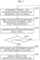
- FIG. 2 illustrates a method for position estimation and direction recognition between objects through a C-ITS linkage in a V2X communication environment according to an embodiment of the present disclosure.
- step S210 the method determines the position and movement path of a device, predicts the future position and movement path, and exchanges the prediction information with surrounding objects.
- step S220 the method performs time synchronization between transmission equipment and reception equipment when it is confirmed that surrounding object information and infrastructure information are being received.
- step S230 the method confirms a reception information latency time t r
- step S240 the method confirms whether the reception information latency time t r is less than a reference time TimeTH r . That is, in relation to time latency information between the transmission equipment and the reception equipment, the time between equipments is confirmed using a network time protocol (NTP) or the like and used when determined to be a valid value.
- NTP network time protocol
- the definition of a valid value is set for each equipment at the discretion of a manufacturer or an administrator (user).
- step S240 When it is confirmed in step S240 that the reception information latency time t r is equal to or greater than the reference time TimeTH r , the procedure returns to step S210. When it is confirmed in step S240 that the reception information latency time t r is less than the reference time TimeTH r , the method performs recognition and determination on the object and surrounding situation in step S250. In step S260, the method displays the object and infrastructure information. Based on the object information transmitted and received between the objects, a user recognizes and determines the current position, movement path, surrounding objects, and surrounding infrastructure situations.
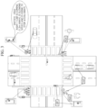
- FIG. 3 illustrates the display of object and infrastructure information according to an embodiment of the present disclosure.
- the situation of each device is considered. For example, since certain expensive equipment can use a neural processing unit (NPU), AI processing can be performed. In addition, since TOPS that can be processed is different depending on the specifications of the NPU, differences may exist in an amount that can be determined, a real-time property, and the degree of accuracy. When information is determined in consideration of such a situation, a manufacturer or an administrator (user) recognizes the presence and absence of the NPU, the TOPS performance of the NPU, and the like, and finally determines object information.
- NPU neural processing unit
- TOPS that can be processed is different depending on the specifications of the NPU, differences may exist in an amount that can be determined, a real-time property, and the degree of accuracy.
- the object and infrastructure information can be displayed as illustrated in FIG. 3 in which pedestrians can determine vehicle information in real-time and confirm the direction, information, speed, and the like of surrounding vehicles in real-time, thereby constructing a safe environment for both the pedestrians and the vehicles in an autonomous road environment.
- information on a position, a type, a current separation distance, a speed, an expected behavior, and a separation distance after the expected behavior of a surrounding object is displayed.
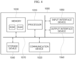
- FIG. 4 is a block diagram showing a computer system for implementing a method according to an embodiment of the present disclosure.
- a computer system 1000 may include at least one of a processor 1010, a memory 1030, an input interface device 1050, an output interface device 1060, and a storage device 1040 that communicate with one another through a bus 1070.
- the computer system 1000 may also include a communication device 1020 coupled to a network.
- the processor 1010 may be a central processing unit (CPU) or a semiconductor device that executes instructions stored in the memory 1030 or the storage device 1040.
- the memory 1030 and the storage device 1040 may include various types of volatile or nonvolatile storage media.
- the memory may include a read only memory (ROM) and a random access memory (RAM).
- the memory may be located inside or outside the processor, and may be connected to the processor through various known means.
- the memory is various forms of volatile or nonvolatile storage media, and for example, may include a read-only memory (ROM) or a random access memory (RAM).
- an embodiment of the present disclosure may be implemented as a computer-implemented method or a non-transitory computer-readable medium storing computer-executable instructions.
- computer readable instructions when executed by a processor, may perform a method according to at least one aspect of the present disclosure.
- the communication device 1020 can transmit or receive wired signals or wireless signals.
- the method according to an embodiment of the present disclosure may be implemented in the form of program instructions that can be executed through various computer means, and recorded on a computer-readable medium.
- the computer-readable medium may include program instructions, data files, data structures, and the like singly or in combination.
- the program instructions recorded on the computer-readable medium may be specially designed and configured for an embodiment of the present disclosure, or may be known to and usable by those skilled in the art of computer software.
- a computer-readable recording medium may include a hardware device configured to store and execute program instructions. Examples of the computer-readable recording medium may include magnetic media such as hard disks, floppy disks, and magnetic tapes, optical media such as CD-ROMs and DVDs, and magneto-optical media such as floptical disks, a ROM, a RAM, and a flash memory.
- the program instructions may include not only machine language code such as that generated by a compiler, but also high-level language code that can be executed by a computer through an interpreter or the like.
Landscapes
- General Physics & Mathematics (AREA)
- Physics & Mathematics (AREA)
- Engineering & Computer Science (AREA)
- Radar, Positioning & Navigation (AREA)
- Remote Sensing (AREA)
- Signal Processing (AREA)
- Computer Networks & Wireless Communication (AREA)
- Chemical & Material Sciences (AREA)
- Analytical Chemistry (AREA)
- Life Sciences & Earth Sciences (AREA)
- Atmospheric Sciences (AREA)
- Automation & Control Theory (AREA)
- Transportation (AREA)
- Mechanical Engineering (AREA)
- Traffic Control Systems (AREA)
Abstract
Provided are a system and a method for position estimation and direction recognition between objects through a C-ITS linkage in a V2X communication environment. The system for position estimation and direction recognition between objects through a C-ITS linkage in a V2X communication environment includes an infrastructure information reception unit configured to receive infrastructure information from an infrastructure, an object position determination unit configured to determine a position of equipment in use, an object position and path prediction unit configured to predict a future position and a movement path of the equipment in use, an object information transmission/reception unit configured to exchange information on the equipment with another object, and an object and surrounding situation recognition and determination unit configured to recognize an object and a surrounding situation and determine whether a dangerous situation exists by using information acquired through a C-ITS linkage in a V2X communication environment.
Description
- This application claims priority to and the benefit of
Korean Patent Application No. 10-2023-0090066, July 11, 2023 - The present disclosure relates to a system and a method for position estimation and direction recognition between objects through a C-ITS linkage in a V2X communication environment.
- According to the related art, there are technical/industrial limitations when objects estimate mutual positions and recognize movement directions, and for example, there are technical limitations in supporting machine to machine (M2M), so communication between equipment needs to be performed through a base station. Although technologies such as WAVE, LTE-V2X, and 5G Uu have developed, there are limitations that make it difficult to provide various services due to issues such as a plurality of terminals, latency time, and transmission capacity.
- According to the related art, a technology has been proposed to convert a motion change rate of an object and a change rate of the number of objects that can be measured based on a position change rate and motion information of an object into energy information, to measure the entropy of the converted energy information, and to recognize a situation within a space where an image has been captured by linking a change rate of the entropy with risk policy (
Korean Patent Application Laid-Open No. 10-2013-0136251 Korean Patent No. 10-2315703 - Various embodiments are directed to a system and a method for position estimation and direction recognition between objects, which can estimate mutual positions of objects and recognize mutual directions of the objects through a C-ITS linkage in a V2X (V2V, V2I, V2P, V2C, and the like) environment to reduce recently increasing vehicle and human casualty accidents in a traffic environment, and establish a safe autonomous driving environment by determining the exact positions of objects in advance in an environment where autonomous vehicles, regular vehicles, connected vehicles, and the like are mixed.
- The present disclosure relates to a system and a method for position estimation and direction recognition between objects through a C-ITS linkage in a V2X communication environment.
- A system for position estimation and direction recognition between objects through a C-ITS linkage in a V2X communication environment according to the present disclosure includes an infrastructure information reception unit configured to receive infrastructure information from an infrastructure, an object position determination unit configured to determine a position of equipment in use, an object position and path prediction unit configured to predict a future position and a movement path of the equipment in use, an object information transmission/reception unit configured to exchange information on the equipment with another object, and an object and surrounding situation recognition and determination unit configured to recognize an object and a surrounding situation and determine whether a dangerous situation exists by using information acquired through a C-ITS linkage in a V2X communication environment.
- The object position determination unit determines the position of the equipment in use by using at least one of GPS, IMU, and UWB positioning devices.
- When a result obtained by comparing a reception information latency time with a reference time is determined to be a valid value, the object and surrounding situation recognition and determination unit determines whether the dangerous situation exists by using the acquired information.
- The system for position estimation and direction recognition between objects through a C-ITS linkage in a V2X communication environment according to the present disclosure further includes an object and infrastructure information display unit configured to display object and infrastructure information by using a determination result regarding whether the dangerous situation exists.
- The object and infrastructure information display unit displays information on a position, a type, a current separation distance, a speed, an expected behavior, and a separation distance after the expected behavior of a surrounding object.
- A method for position estimation and direction recognition between objects through a C-ITS linkage in a V2X communication environment according to the present disclosure includes (a) determining, by a first object and a second object, positions and movement paths of the first object and the second object, and generating information on future expected positions and expected movement paths of the first object and the second object, (b) exchanging, by the first object and the second object, information on the expected positions and the expected movement paths with each other, (c) confirming reception information latency times of the first object and the second object, and recognizing and determining a surrounding situation to decide whether a dangerous situation exists when the reception information latency times are determined to be valid values, and (d) displaying object and infrastructure information according to a decision result regarding whether the dangerous situation exists.
- In (c) of confirming, time synchronization between the first object and the second object is performed, and whether the reception information latency times are valid values is determined according to a result obtained by comparing the reception information latency times with a reference time set by a manufacturer or an administrator for each equipment.
- The present disclosure can respond to a dangerous situation by recognizing and determining positions, movement paths, and infrastructure information between objects in advance.
- According to the present disclosure, safe and smooth movement is possible in preparation for dangerous situations in a mixed environment of autonomous vehicles, connected vehicles, general vehicles, pedestrians, and infrastructure.
- The effects of the present disclosure are not limited to the above-mentioned effects, and the other effects which are not mentioned herein will be clearly understood from the following descriptions by those skilled in the art.
-
-
FIG. 1 illustrates a system for position estimation and direction recognition between objects through a C-ITS linkage in a V2X communication environment according to an embodiment of the present disclosure. -
FIG. 2 illustrates a method for position estimation and direction recognition between objects through a C-ITS linkage in a V2X communication environment according to an embodiment of the present disclosure. -
FIG. 3 illustrates the display of object and infrastructure information according to an embodiment of the present disclosure. -
FIG. 4 is a block diagram illustrating a computer system for implementing a method according to an embodiment of the present disclosure. - The above-described object, other objects, advantages, and characteristics of the present disclosure and a method for achieving them will become apparent from embodiments to be described in detail below together with the accompanying drawings.
- However, the present disclosure is not limited to the embodiments to be disclosed below, but may be implemented in various forms different from each other, and the following embodiments are merely provided to easily inform those skilled in the art in the art to which the present disclosure pertains of the object, configuration, and effect of the present disclosure. Therefore, the scope of the present disclosure is defined by the claims.
- Terms used in the present specification are used for describing embodiments and are not intended to limit the present disclosure. In this specification, an expression of the singular number includes an expression of the plural number unless clearly defined otherwise in the context. The term "comprises" and/or "comprising" used in this specification does not exclude the presence or addition of one or more other elements, steps, operations, and/or elements in addition to a mentioned element, step, operation, and/or element.
-
FIG. 1 illustrates a system for position estimation and direction recognition between objects through a C-ITS linkage in a V2X communication environment according to an embodiment of the present disclosure. The V2X communication environment is not limited to WAVE, LTE, 5G-Uu, 5G-NR-V2X, 6G, and the like, and includes all communication environments used in V2X. With the development of communication technologies such as 5G-NR-V2X, technical limitations in the related art have been continuously improved, so that real-time low-latency transmission and reception of high-capacity transmission data becomes possible. An embodiment of the present disclosure proposes, in consideration of new technology trends, a system and a method for position estimation and direction recognition between objects through a C-ITS linkage in a V2X communication environment by using communication technologies between vehicle to vehicle (V2V), vehicle to infra (V2I), and vehicle to pedestrian (V2P) in a communication environment such as 5G-Uu and 5G-NR-V2X. Specifically, an embodiment of the present disclosure proposes 1) Technology for ascertaining the position of communication equipment, 2) Technology for ascertaining the movement direction and expected movement path and time of communication equipment, 3) Technology for transmitting and receiving mutual positions, movement directions, and expected movement paths and times of communication equipment, 4) Technology for estimating mutual positions of communication equipment and receiving and recognizing direction and infrastructure information, and 5) Technology for displaying information on the positions, movement paths, and infrastructure of communication equipment. - An infrastructure
information transmission unit 100 transmits infrastructure information including signal information and unexpected situation information. Afirst object 200 includes an infrastructureinformation reception unit 210, an objectposition determination unit 220, an object position andpath prediction unit 230, an object information transmission/reception unit 240, and an object and surrounding situation recognition anddetermination unit 250, and an object and infrastructureinformation display unit 260. - The object
position determination unit 220 determines the position of corresponding equipment being used by a user. The object position andpath prediction unit 230 predicts the position and path of the equipment being used by the user. The object position andpath prediction unit 230 determines the position of the equipment in use by using a positioning device such as GPS, IMU, and UWB. The object position andpath prediction unit 230 determines the predicted path in consideration of the position, movement direction, speed, and the like of the equipment in use, and transmits/receives the determined information between objects (that is, thefirst object 200 and a second object300) through a C-ITS linkage in a V2X communication environment to ascertain mutual position information. The object information transmission/reception unit 240 communicates with an object information transmission/reception unit of thesecond object 300, thereby transmitting information on thefirst object 200 and receiving information on thesecond object 300. The object and surrounding situation recognition anddetermination unit 250 recognizes the object and surrounding situation and determines whether a dangerous situation exists by using infrastructure information received through the infrastructureinformation reception unit 210 and object position and path prediction information. The object and infrastructureinformation display unit 260 displays information on a user, surrounding objects, and infrastructure. -
FIG. 2 illustrates a method for position estimation and direction recognition between objects through a C-ITS linkage in a V2X communication environment according to an embodiment of the present disclosure. - In step S210, the method determines the position and movement path of a device, predicts the future position and movement path, and exchanges the prediction information with surrounding objects.
- In step S220, the method performs time synchronization between transmission equipment and reception equipment when it is confirmed that surrounding object information and infrastructure information are being received.
- In step S230, the method confirms a reception information latency time tr, and in step S240, the method confirms whether the reception information latency time tr is less than a reference time TimeTHr. That is, in relation to time latency information between the transmission equipment and the reception equipment, the time between equipments is confirmed using a network time protocol (NTP) or the like and used when determined to be a valid value. In such a case, the definition of a valid value is set for each equipment at the discretion of a manufacturer or an administrator (user).
- When it is confirmed in step S240 that the reception information latency time tr is equal to or greater than the reference time TimeTHr, the procedure returns to step S210. When it is confirmed in step S240 that the reception information latency time tr is less than the reference time TimeTHr, the method performs recognition and determination on the object and surrounding situation in step S250. In step S260, the method displays the object and infrastructure information. Based on the object information transmitted and received between the objects, a user recognizes and determines the current position, movement path, surrounding objects, and surrounding infrastructure situations.
-
FIG. 3 illustrates the display of object and infrastructure information according to an embodiment of the present disclosure. - According to an embodiment of the present disclosure, the situation of each device is considered. For example, since certain expensive equipment can use a neural processing unit (NPU), AI processing can be performed. In addition, since TOPS that can be processed is different depending on the specifications of the NPU, differences may exist in an amount that can be determined, a real-time property, and the degree of accuracy. When information is determined in consideration of such a situation, a manufacturer or an administrator (user) recognizes the presence and absence of the NPU, the TOPS performance of the NPU, and the like, and finally determines object information.
- The object and infrastructure information can be displayed as illustrated in
FIG. 3 in which pedestrians can determine vehicle information in real-time and confirm the direction, information, speed, and the like of surrounding vehicles in real-time, thereby constructing a safe environment for both the pedestrians and the vehicles in an autonomous road environment. - According to an embodiment of the present disclosure, information on a position, a type, a current separation distance, a speed, an expected behavior, and a separation distance after the expected behavior of a surrounding object is displayed.
-
FIG. 4 is a block diagram showing a computer system for implementing a method according to an embodiment of the present disclosure. - Referring to
FIG. 4 , acomputer system 1000 may include at least one of aprocessor 1010, amemory 1030, aninput interface device 1050, anoutput interface device 1060, and astorage device 1040 that communicate with one another through abus 1070. Thecomputer system 1000 may also include acommunication device 1020 coupled to a network. Theprocessor 1010 may be a central processing unit (CPU) or a semiconductor device that executes instructions stored in thememory 1030 or thestorage device 1040. Thememory 1030 and thestorage device 1040 may include various types of volatile or nonvolatile storage media. For example, the memory may include a read only memory (ROM) and a random access memory (RAM). In an embodiment of the present disclosure, the memory may be located inside or outside the processor, and may be connected to the processor through various known means. The memory is various forms of volatile or nonvolatile storage media, and for example, may include a read-only memory (ROM) or a random access memory (RAM). - Accordingly, an embodiment of the present disclosure may be implemented as a computer-implemented method or a non-transitory computer-readable medium storing computer-executable instructions. In an embodiment, when executed by a processor, computer readable instructions may perform a method according to at least one aspect of the present disclosure.
- The
communication device 1020 can transmit or receive wired signals or wireless signals. - The method according to an embodiment of the present disclosure may be implemented in the form of program instructions that can be executed through various computer means, and recorded on a computer-readable medium.
- The computer-readable medium may include program instructions, data files, data structures, and the like singly or in combination. The program instructions recorded on the computer-readable medium may be specially designed and configured for an embodiment of the present disclosure, or may be known to and usable by those skilled in the art of computer software. A computer-readable recording medium may include a hardware device configured to store and execute program instructions. Examples of the computer-readable recording medium may include magnetic media such as hard disks, floppy disks, and magnetic tapes, optical media such as CD-ROMs and DVDs, and magneto-optical media such as floptical disks, a ROM, a RAM, and a flash memory. The program instructions may include not only machine language code such as that generated by a compiler, but also high-level language code that can be executed by a computer through an interpreter or the like.
- Although the embodiments of the present invention have been described in detail above, the scope of the present invention is not limited thereto, and various modifications and improvements made by those skilled in the art using the basic concept of the present invention defined in the following claims are included in the scope of the present disclosure.
Claims (7)
- A system for position estimation and direction recognition between objects through a C-ITS linkage in a V2X communication environment, comprising:an infrastructure information reception unit configured to receive infrastructure information from an infrastructure;an object position determination unit configured to determine a position of equipment in use;an object position and path prediction unit configured to predict a future position and a movement path of the equipment in use;an object information transmission/reception unit configured to exchange information on the equipment with another object; andan object and surrounding situation recognition and determination unit configured to recognize an object and a surrounding situation and determine whether a dangerous situation exists by using information acquired through a C-ITS linkage in a V2X communication environment.
- The system for position estimation and direction recognition between objects through a C-ITS linkage in a V2X communication environment of claim 1, wherein the object position determination unit determines the position of the equipment in use by using at least one of GPS, IMU, and UWB positioning devices.
- The system for position estimation and direction recognition between objects through a C-ITS linkage in a V2X communication environment of claim 1, wherein, when a result obtained by comparing a reception information latency time with a reference time is determined to be a valid value, the object and surrounding situation recognition and determination unit determines whether the dangerous situation exists by using the acquired information.
- The system for position estimation and direction recognition between objects through a C-ITS linkage in a V2X communication environment of claim 1, further comprising:
an object and infrastructure information display unit configured to display object and infrastructure information by using a determination result regarding whether the dangerous situation exists. - The system for position estimation and direction recognition between objects through a C-ITS linkage in a V2X communication environment of claim 4, wherein the object and infrastructure information display unit displays information on a position, a type, a current separation distance, a speed, an expected behavior, and a separation distance after the expected behavior of a surrounding object.
- A method for position estimation and direction recognition between objects through a C-ITS linkage in a V2X communication environment, comprising:(a) determining, by a first object and a second object, positions and movement paths of the first object and the second object, and generating information on future expected positions and expected movement paths of the first object and the second object;(b) exchanging, by the first object and the second object, information on the expected positions and the expected movement paths with each other;(c) confirming reception information latency times of the first object and the second object, and recognizing and determining a surrounding situation to decide whether a dangerous situation exists when the reception information latency times are determined to be valid values; and(d) displaying object and infrastructure information according to a decision result regarding whether the dangerous situation exists.
- The method for position estimation and direction recognition between objects through a C-ITS linkage in a V2X communication environment of claim 6, wherein in (c) of confirming, time synchronization between the first object and the second object is performed, and whether the reception information latency times are valid values is determined according to a result obtained by comparing the reception information latency times with a reference time set by a manufacturer or an administrator for each equipment.
Applications Claiming Priority (1)
| Application Number | Priority Date | Filing Date | Title |
|---|---|---|---|
| KR1020230090066A KR102839047B1 (en) | 2023-07-11 | 2023-07-11 | System and method for position estimation and direction recognition between objects through c-its linkage in v2x communication environment |
Publications (1)
| Publication Number | Publication Date |
|---|---|
| EP4492356A1 true EP4492356A1 (en) | 2025-01-15 |
Family
ID=91432726
Family Applications (1)
| Application Number | Title | Priority Date | Filing Date |
|---|---|---|---|
| EP24180366.7A Pending EP4492356A1 (en) | 2023-07-11 | 2024-06-06 | System and method for position estimation and direction recognition between objects through c-its linkage in v2x communication environment |
Country Status (4)
| Country | Link |
|---|---|
| US (1) | US20250020754A1 (en) |
| EP (1) | EP4492356A1 (en) |
| JP (1) | JP2025013184A (en) |
| KR (1) | KR102839047B1 (en) |
Citations (10)
| Publication number | Priority date | Publication date | Assignee | Title |
|---|---|---|---|---|
| US20130120159A1 (en) * | 2010-07-29 | 2013-05-16 | Continental Teves Ag & Co. Ohg | Device and method for c2x communication |
| KR20130136251A (en) | 2012-06-04 | 2013-12-12 | 한국전자통신연구원 | Method and apparatus for situation recognition using object energy function |
| US20180199298A1 (en) * | 2015-07-29 | 2018-07-12 | Sony Corporation | Communications devices and methods |
| US20180255525A1 (en) * | 2015-11-06 | 2018-09-06 | Sony Corporation | Communication device and communication method |
| US20210065551A1 (en) * | 2019-08-29 | 2021-03-04 | Derq Inc. | Enhanced Onboard Equipment |
| US20210264689A1 (en) * | 2020-02-24 | 2021-08-26 | Ford Global Technologies, Llc | Vehicle error alerting system |
| KR102315703B1 (en) | 2019-04-08 | 2021-10-20 | 한국교통대학교산학협력단 | A method and apparatus for sharing object sensing information of infra sensor |
| US20220030430A1 (en) * | 2020-07-23 | 2022-01-27 | Qualcomm Incorporated | Techniques for managing data distribution in a v2x environment |
| US20220397415A1 (en) * | 2021-06-14 | 2022-12-15 | Ford Global Technologies, Llc | V2x message-based tracker application |
| KR20230090066A (en) | 2021-12-14 | 2023-06-21 | 한국전력공사 | Communication cable support device of power pole |
Family Cites Families (2)
| Publication number | Priority date | Publication date | Assignee | Title |
|---|---|---|---|---|
| KR102739588B1 (en) * | 2019-09-05 | 2024-12-06 | 삼성전자주식회사 | Electronic Device For Supporting Wireless Mobile Communication For Vehicle and Method For Operating The same |
| KR102287169B1 (en) * | 2019-12-24 | 2021-08-09 | (주)에이텍티앤 | Cooperative-Intelligent Transport System for General Vehicles |
-
2023
- 2023-07-11 KR KR1020230090066A patent/KR102839047B1/en active Active
-
2024
- 2024-06-05 US US18/734,485 patent/US20250020754A1/en active Pending
- 2024-06-06 EP EP24180366.7A patent/EP4492356A1/en active Pending
- 2024-06-06 JP JP2024092581A patent/JP2025013184A/en active Pending
Patent Citations (10)
| Publication number | Priority date | Publication date | Assignee | Title |
|---|---|---|---|---|
| US20130120159A1 (en) * | 2010-07-29 | 2013-05-16 | Continental Teves Ag & Co. Ohg | Device and method for c2x communication |
| KR20130136251A (en) | 2012-06-04 | 2013-12-12 | 한국전자통신연구원 | Method and apparatus for situation recognition using object energy function |
| US20180199298A1 (en) * | 2015-07-29 | 2018-07-12 | Sony Corporation | Communications devices and methods |
| US20180255525A1 (en) * | 2015-11-06 | 2018-09-06 | Sony Corporation | Communication device and communication method |
| KR102315703B1 (en) | 2019-04-08 | 2021-10-20 | 한국교통대학교산학협력단 | A method and apparatus for sharing object sensing information of infra sensor |
| US20210065551A1 (en) * | 2019-08-29 | 2021-03-04 | Derq Inc. | Enhanced Onboard Equipment |
| US20210264689A1 (en) * | 2020-02-24 | 2021-08-26 | Ford Global Technologies, Llc | Vehicle error alerting system |
| US20220030430A1 (en) * | 2020-07-23 | 2022-01-27 | Qualcomm Incorporated | Techniques for managing data distribution in a v2x environment |
| US20220397415A1 (en) * | 2021-06-14 | 2022-12-15 | Ford Global Technologies, Llc | V2x message-based tracker application |
| KR20230090066A (en) | 2021-12-14 | 2023-06-21 | 한국전력공사 | Communication cable support device of power pole |
Non-Patent Citations (1)
| Title |
|---|
| LG ELECTRONICS: "Potential enhancements for PC5-based V2V", vol. RAN WG1, no. Beijing, China; 20150824 - 20150828, 23 August 2015 (2015-08-23), XP051001618, Retrieved from the Internet <URL:http://www.3gpp.org/ftp/Meetings_3GPP_SYNC/RAN1/Docs/> [retrieved on 20150823] * |
Also Published As
| Publication number | Publication date |
|---|---|
| US20250020754A1 (en) | 2025-01-16 |
| KR102839047B1 (en) | 2025-07-28 |
| KR20250009857A (en) | 2025-01-20 |
| KR102839047B9 (en) | 2026-04-09 |
| JP2025013184A (en) | 2025-01-24 |
Similar Documents
| Publication | Publication Date | Title |
|---|---|---|
| EP3994626B1 (en) | Receding horizon state estimator | |
| JP5741390B2 (en) | Frequency selection method and cognitive radio system | |
| US20200302639A1 (en) | Apparatus and method for managing feature point map | |
| EP3089528B1 (en) | Base station positioning method and apparatus | |
| KR20180054268A (en) | Apparatus and computer readable recording medium for warning dangerous situation | |
| US12190595B2 (en) | Information processing apparatus, information processing system, and information processing method | |
| US20110299736A1 (en) | Apparatus for localization using image and range data and method thereof | |
| US11645913B2 (en) | System and method for location data fusion and filtering | |
| WO2011046113A1 (en) | Behavior type eduction system, device, method, program, and recording medium in which said program is recorded | |
| CN110470308A (en) | An obstacle avoidance system and method | |
| US20240289165A1 (en) | System framework for software and hardware configuration determination for vehicle applications with cloud and edge computing | |
| CN109691063B (en) | Method and apparatus for receiving, processing and transmitting data | |
| CN108334085A (en) | Smart collaboration method, apparatus, system, intelligent terminal and storage medium | |
| EP3813035A1 (en) | Vehicle control method and device | |
| US20250020754A1 (en) | System and method for position estimation and direction recognition between objects through c-its linkage in v2x communication environment | |
| US12172668B2 (en) | Vehicles and methods for sharing sensor data based on criticality | |
| KR20170044940A (en) | Apparatus and method for moving path prediction of vehicle | |
| JP2012133725A (en) | Congestion determining device and congestion determining method | |
| JP7314314B2 (en) | In-vehicle system and method for receiving and transmitting sensing data | |
| KR101978578B1 (en) | Method for Estimating Position/Heading Information of Communication Device without GPS Module | |
| KR101893707B1 (en) | Method of Locating Users of Smart Devices by Analyzing Wireless Signal based on Fuzzy Logic for Accurate Location Information | |
| KR102452552B1 (en) | Apparatus for controlling V2X message transmitting based-on channel occupancy, system having the same and method thereof | |
| CN120178881B (en) | A robot path planning method and system | |
| CN116017267B (en) | Information processing methods and electronic devices | |
| US11922330B2 (en) | Apparatus and method for estimating a physical state of a movable object |
Legal Events
| Date | Code | Title | Description |
|---|---|---|---|
| PUAI | Public reference made under article 153(3) epc to a published international application that has entered the european phase |
Free format text: ORIGINAL CODE: 0009012 |
|
| STAA | Information on the status of an ep patent application or granted ep patent |
Free format text: STATUS: THE APPLICATION HAS BEEN PUBLISHED |
|
| AK | Designated contracting states |
Kind code of ref document: A1 Designated state(s): AL AT BE BG CH CY CZ DE DK EE ES FI FR GB GR HR HU IE IS IT LI LT LU LV MC ME MK MT NL NO PL PT RO RS SE SI SK SM TR |
|
| STAA | Information on the status of an ep patent application or granted ep patent |
Free format text: STATUS: REQUEST FOR EXAMINATION WAS MADE |
|
| 17P | Request for examination filed |
Effective date: 20250714 |