EP4492180A1 - Control method and apparatus for wheel-legged robot, robot, and storage medium - Google Patents
Control method and apparatus for wheel-legged robot, robot, and storage medium Download PDFInfo
- Publication number
- EP4492180A1 EP4492180A1 EP22930638.6A EP22930638A EP4492180A1 EP 4492180 A1 EP4492180 A1 EP 4492180A1 EP 22930638 A EP22930638 A EP 22930638A EP 4492180 A1 EP4492180 A1 EP 4492180A1
- Authority
- EP
- European Patent Office
- Prior art keywords
- wheel
- wheel leg
- stair
- leg
- controlling
- Prior art date
- Legal status (The legal status is an assumption and is not a legal conclusion. Google has not performed a legal analysis and makes no representation as to the accuracy of the status listed.)
- Granted
Links
Images



Classifications
-
- B—PERFORMING OPERATIONS; TRANSPORTING
- B25—HAND TOOLS; PORTABLE POWER-DRIVEN TOOLS; MANIPULATORS
- B25J—MANIPULATORS; CHAMBERS PROVIDED WITH MANIPULATION DEVICES
- B25J9/00—Program-controlled manipulators
- B25J9/16—Program controls
- B25J9/1656—Program controls characterised by programming, planning systems for manipulators
- B25J9/1664—Program controls characterised by programming, planning systems for manipulators characterised by motion, path, trajectory planning
-
- B—PERFORMING OPERATIONS; TRANSPORTING
- B25—HAND TOOLS; PORTABLE POWER-DRIVEN TOOLS; MANIPULATORS
- B25J—MANIPULATORS; CHAMBERS PROVIDED WITH MANIPULATION DEVICES
- B25J13/00—Controls for manipulators
- B25J13/08—Controls for manipulators by means of sensing devices, e.g. viewing or touching devices
- B25J13/085—Force or torque sensors
-
- B—PERFORMING OPERATIONS; TRANSPORTING
- B25—HAND TOOLS; PORTABLE POWER-DRIVEN TOOLS; MANIPULATORS
- B25J—MANIPULATORS; CHAMBERS PROVIDED WITH MANIPULATION DEVICES
- B25J13/00—Controls for manipulators
- B25J13/08—Controls for manipulators by means of sensing devices, e.g. viewing or touching devices
- B25J13/088—Controls for manipulators by means of sensing devices, e.g. viewing or touching devices with position, velocity or acceleration sensors
- B25J13/089—Determining the position of the robot with reference to its environment
-
- B—PERFORMING OPERATIONS; TRANSPORTING
- B62—LAND VEHICLES FOR TRAVELLING OTHERWISE THAN ON RAILS
- B62D—MOTOR VEHICLES; TRAILERS
- B62D57/00—Vehicles characterised by having other propulsion or other ground- engaging means than wheels or endless track, alone or in addition to wheels or endless track
- B62D57/02—Vehicles characterised by having other propulsion or other ground- engaging means than wheels or endless track, alone or in addition to wheels or endless track with ground-engaging propulsion means, e.g. walking members
- B62D57/024—Vehicles characterised by having other propulsion or other ground- engaging means than wheels or endless track, alone or in addition to wheels or endless track with ground-engaging propulsion means, e.g. walking members specially adapted for moving on inclined or vertical surfaces
-
- B—PERFORMING OPERATIONS; TRANSPORTING
- B62—LAND VEHICLES FOR TRAVELLING OTHERWISE THAN ON RAILS
- B62D—MOTOR VEHICLES; TRAILERS
- B62D57/00—Vehicles characterised by having other propulsion or other ground- engaging means than wheels or endless track, alone or in addition to wheels or endless track
- B62D57/02—Vehicles characterised by having other propulsion or other ground- engaging means than wheels or endless track, alone or in addition to wheels or endless track with ground-engaging propulsion means, e.g. walking members
- B62D57/028—Vehicles characterised by having other propulsion or other ground- engaging means than wheels or endless track, alone or in addition to wheels or endless track with ground-engaging propulsion means, e.g. walking members having wheels and mechanical legs
-
- G—PHYSICS
- G05—CONTROLLING; REGULATING
- G05D—SYSTEMS FOR CONTROLLING OR REGULATING NON-ELECTRIC VARIABLES
- G05D1/00—Control of position, course, altitude or attitude of land, water, air or space vehicles, e.g. using automatic pilots
- G05D1/08—Control of attitude, i.e. control of roll, pitch, or yaw
-
- G—PHYSICS
- G05—CONTROLLING; REGULATING
- G05D—SYSTEMS FOR CONTROLLING OR REGULATING NON-ELECTRIC VARIABLES
- G05D1/00—Control of position, course, altitude or attitude of land, water, air or space vehicles, e.g. using automatic pilots
- G05D1/40—Control within particular dimensions
- G05D1/49—Control of attitude, i.e. control of roll, pitch or yaw
Definitions
- Embodiments of this application relate to the field of robots, and in particular, to a method and apparatus for controlling a wheel-legged robot, a robot, and a storage medium.
- a wheel-legged robot is a robot that controls the motion of a robot main body through a wheel-legged structure.
- the agility and flexibility of the wheel-legged robot in ground motion have attracted widespread attention of researchers. How to control the wheel-legged robot to achieve more actions is currently a main research direction.
- Embodiments of this application provide a method and apparatus for controlling a wheel-legged robot, a robot, and a storage medium.
- One aspect provides a method for controlling a wheel-legged robot, the wheel-legged robot including a first wheel leg, a second wheel leg, and an auxiliary wheel leg, and the method including: controlling the first wheel leg to move from a first stair onto a second stair, while controlling the second wheel leg and the auxiliary wheel leg to remain in their positions on the first stair, wherein the first stair and the second stair have different stair heights; controlling the second wheel leg to move from the first stair onto the second stair, controlling the first wheel leg to remain in its position on the second stair, and controlling the auxiliary wheel leg to remain in its position on the first stair; and controlling the auxiliary wheel leg to move from the first stair onto the second stair, and controlling the first wheel leg and the second wheel leg to stay on the second stair.
- One aspect provides an apparatus for controlling a wheel-legged robot, the wheel-legged robot including a first wheel leg, a second wheel leg, and an auxiliary wheel leg, and the apparatus including: a first wheel leg control module, configured to: control the first wheel leg to move from a first stair onto a second stair, while controlling the second wheel leg and the auxiliary wheel leg to remain in their positions on the first stair, wherein the first stair and the second stair have different stair heights; a second wheel leg control module, configured to: control the second wheel leg to move from the first stair onto the second stair, while controlling the first wheel leg to remain in its position on the second stair, and controlling the auxiliary wheel leg to remain in its position on the first stair; and an auxiliary wheel leg control module, configured to: control the auxiliary wheel leg to move from the first stair onto the second stair, while controlling the first wheel leg and the second wheel leg to stay on the second stair.
- a first wheel leg control module configured to: control the first wheel leg to move from a
- One aspect provides a wheel-legged robot, the wheel-legged robot including a first wheel leg, a second wheel leg, an auxiliary wheel leg, a base, one or more central processing units, and one or more memories, the base being located above the first wheel leg, the second wheel leg, and the auxiliary wheel leg and being connected to the first wheel leg, the second wheel leg, and the auxiliary wheel leg; the one or more memories storing at least one computer program; and the at least one computer program being loaded and executed by the one or more central processing units to implement the method for controlling the wheel-legged robot.
- One aspect provides a computer-readable storage medium, the computer-readable storage medium storing at least one computer program, and the at least one computer program being loaded and executed by a central processing unit to implement the method for controlling the wheel-legged robot.
- One aspect provides a computer program product, the computer program product including at least one computer program, and the at least one computer program being stored in a computer-readable storage medium.
- a central processing unit of a wheel-legged robot reads the at least one computer program from the computer-readable storage medium, and the central processing unit executes the at least one computer program, causing the wheel-legged robot to implement the method for controlling the wheel-legged robot.
- first”, “second”, and the like used in this application are used for distinguishing identical or similar items that have essentially the same effects and functions. It should be understood that there is no logical or temporal dependency relationship between “first”, “second”, and “nth”, and there is no limitation on quantities and execution orders.
- a robot is a mechanical and electronic device that is a combination of mechanical transmission and a modern microelectronics technology to imitate a certain skill of a person.
- robots have been greatly improved in terms of functionality and technical level.
- Mobile robots and visual and tactile technologies of the robots are typical representatives.
- Wheel-legged robot is a robot that controls the motion of the robot through a wheel-legged structure. It has extremely high wheel energy and extremely strong adaptability and can adapt to uneven terrains.
- the wheel-legged structure includes two parts: a leg containing at least one j oint; and a wheel. Due to the fact that wheel-legged robots only contact the ground through wheels of their wheel legs, there is often a problem of balance control.
- FIG. 1 is a schematic diagram of an implementation environment of a method for controlling a wheel-legged robot provided in the embodiments of this application.
- the implementation environment includes a wheel-legged robot 100 and a control device 200.
- the wheel-legged robot 100 and the control device 200 are connected to each other through a wired or wireless network.
- the wheel-legged robot 100 includes a first wheel leg 110, a second wheel leg 120, an auxiliary wheel leg 130, and a base 140.
- the base 140 is located above the first wheel leg 110, the second wheel leg 120, and the auxiliary wheel leg 130 and is connected to the first wheel leg 110, the second wheel leg 120, and the auxiliary wheel leg 130.
- the first wheel leg 110 and the second wheel leg 120 are configured to drive the robot to move.
- the structure of the first wheel leg 110 and the structure of the second wheel leg 120 are the same.
- the first wheel leg 110 includes two leg structures 111 and a wheel 112.
- the two leg structures 111 are connected to the wheel 112.
- Each of the two leg structures 111 includes a thigh structure 1111 and a lower leg structure 1112, that is, the first wheel leg 110 includes two thigh structures 1111 and two lower leg structures 1112.
- Each thigh structure 1111 and one matching lower leg structure 1112 are connected through a rotational joint.
- Each of the two leg structures 111 is associated with one first motor 150, and each first motor 150 is connected to the thigh structure 1111 in the associated leg structure 111 and is configured to control the associated leg structure 111 to extend and retract. That is, the first wheel leg 110 is controlled by the two first motors 150, and the two thigh structures 1111 of the first wheel leg 110 are respectively connected to the base 140 through output shafts of the respective associated first motors 150.
- the wheel 112 is a driving wheel.
- the wheel 112 can be driven by a second motor 160 to actively rotate, thereby controlling the wheel-legged robot 100 to perform designated actions, such as: controlling the wheel-legged robot to move forwards, controlling the wheel-legged robot to move backwards, controlling the wheel-legged robot to turn, controlling the wheel-legged robot to stand still, or the like.
- the second motor 160 is fixed on one lower leg structure 1112 of the first wheel leg 110 to drive a rotating shaft of the wheel 112 (namely, the driving wheel) through belt transmission, to drive the driving wheel.
- the auxiliary wheel leg 130 is configured to assist the wheel-legged robot in maintaining balance, so that the wheel-legged robot can complete complex actions such as going upstairs.
- the auxiliary wheel leg 130 includes an auxiliary wheel leg 131 and an auxiliary wheel 132.
- the auxiliary wheel leg 131 is connected to the base 140 through an output shaft of a third motor 170.
- the third motor 170 is configured to control the auxiliary wheel leg 130 to swing up and down relative to the base.
- the auxiliary wheel 132 is a driven wheel. In a case that the auxiliary wheel leg 130 contacts the ground, the auxiliary wheel 132 can roll on the ground as the wheel-legged robot 100 moves.
- the wheel-legged robot 100 also includes hardware structures such as a central processing unit and a battery.
- the central processing unit and the battery are mounted in the base 140.
- the central processing unit is configured to control the wheel-legged robot to perform various actions.
- the central processing unit is an independent hardware structure, or the wheel-legged robot includes a microcomputer.
- the central processing unit is integrated into the microcomputer.
- the control device 200 is a terminal or a remote controller.
- the terminal includes a smartphone, a tablet, a laptop, a desktop computer, and the like. The embodiments of this application do not limit this.
- the control device 200 is configured to send a control command to the wheel-legged robot 100 to control the wheel-legged robot 100 to perform actions indicated by the control command.
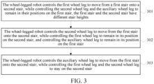
- FIG. 3 is a flowchart of a method for controlling a wheel-legged robot provided according to an embodiment of this application. The method is performed by a central processing unit of the wheel-legged robot. As shown in FIG. 3 , this embodiment includes the following steps.
- the wheel-legged robot controls the first wheel leg to move from a first stair onto a second stair, while controlling the second wheel leg and the auxiliary wheel leg to remain in their positions on the first stair, the first stair and the second stair have different stair heights.
- a stair height indicates the height of a stair.
- a height of a stair may be the height of the horizontal surface of the stair.
- the stair height of the first stair is higher or lower than that of the second stair.
- the wheel-legged robot controls the first wheel leg to perform a second step following a first step, while controlling the second wheel leg and the auxiliary wheel leg to remain in their positions after performing the first step.
- the first step is a step for moving onto the first stair
- the first second is a step for moving onto the second stair
- the positions of the first wheel leg, the second wheel leg and the auxiliary wheel on a stair indicate the positions of the contact points with the stair (also be referred to as stair contact points) of the first wheel leg, the second wheel leg and the auxiliary wheel.
- the second stair is higher than the first stair. That is, the process that the first wheel leg moves from the first stair to the second stair is a process that the wheel-legged robot performs an action of going upstairs.
- the central processing unit first controls the wheel-legged robot to keep balance on the first stair by taking the above three wheel legs as supports, and then controls one wheel leg to move and the other two wheel legs to remain stationary, so that the wheel-legged robot can keep balance in the process that the wheel-legged robot performs the action of going upstairs.
- the wheel-legged robot controls the second wheel leg to move from the first stair onto the second stair, while controlling the first wheel leg to remain in its position on the second stair, and controlling the auxiliary wheel leg to remain in its position on the first stair.
- the wheel-legged robot controls the second wheel leg to perform a second step following a first step, while controlling the first wheel leg to remain in its position after performing the second step, and controlling the auxiliary wheel leg to remain in its position after performing the first step.
- the wheel-legged robot controls the auxiliary wheel leg to move from the first stair onto the second stair, while controlling the first wheel leg and the second wheel leg to stay on the second stair.
- controls the auxiliary wheel leg to perform a second step following a first step, while controlling the first wheel leg and the second wheel leg to stay on the second stair after performing the second step.
- the wheel-legged robot controls the above three wheel legs based on stair information, so as to control the wheel-legged robot to perform the action of going upstairs.
- the stair information is used for describing features of the stairs and a position of the wheel-legged robot relative to the stairs, and includes widths of the stairs, the height difference between the first stair and the second stair, a distance between the wheel-legged robot and the first stair or the second stair, and the like.
- the wheel-legged robot obtains the stair information in two ways.
- a skilled person sends a control command to the wheel-legged robot through the control device.
- the control command carries the stair information.
- the central processing unit of the wheel-legged robot receives the control command and obtains the stair information carried by the control command.
- the wheel-legged robot is provided with an image acquisition sensor.
- the image acquisition sensor may acquire an image containing the first stair and the second stair.
- the wheel-legged robot acquires the stair information based on the image acquired by the image acquisition sensor.
- the first wheel leg, the second wheel leg, and the auxiliary wheel leg are controlled to move from the first stair to the second stair in sequence, and the other two wheel legs are controlled to remain in their positions on the stair when moving any wheel leg, so that in a case of ensuring the balance of the wheel-legged robot, the function of the wheel-legged robot for going upstairs is realized, the diversity of actions and functions of the wheel-legged robot is improved, and the adaptability of the wheel-legged robot to the ground is also improved.
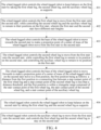
- FIG. 4 is a flowchart of a method for controlling a wheel-legged robot provided according to an embodiment of this application. The embodiments of this application are explained by taking the following as an example: the wheel-legged robot obtains stair information based on an image acquisition sensor. As shown in FIG. 4 , the method is performed by the wheel-legged robot, and includes the following steps.
- the wheel-legged robot controls the wheel-legged robot to keep balance on the first stair by taking the first wheel leg, the second wheel leg, and the auxiliary wheel leg as supports.
- the wheel-legged robot controls the first wheel leg, the second wheel leg, and the auxiliary wheel leg to remain stationary on the first stair, or adjusts the first wheel leg, the second wheel leg, and the auxiliary wheel leg to a stable state.
- the process of adjusting the three wheel legs to the stable state will be described below.
- the wheel-legged robot controls the base of the wheel-legged robot to move downwards, so that the auxiliary wheel leg connected to the base contacts the first stair, and controls a projection point of a center of mass of the wheel-legged robot on the first stair to be within a triangular range composed of a stair contact point of the first wheel leg, a stair contact point of the second wheel leg, and a stair contact point of the auxiliary wheel leg.
- the wheel-legged robot obtains a distance between the auxiliary wheel leg and the first stair based on the image sent by the image acquisition sensor; obtains, based on the distance between the auxiliary wheel leg and the first stair and a wheel leg moving direction indicated by a retraction action, a target joint torque ⁇ 1 of a motor associated with the first wheel leg and a target joint torque ⁇ 2 of a motor associated with the second wheel leg, that is, obtains the target joint torque ⁇ 1 of the two first motors 150 associated with the first wheel leg in FIG.
- the target joint torque ⁇ 1 is a vector including two torques. Each torque corresponds to one first motor of the first wheel leg, that is, each torque is used for controlling one first motor of the first wheel leg.
- the two torques are the same or different.
- a data form of the target j oint torque ⁇ 2 is similar to that of the target j oint torque ⁇ 1 , and will not be repeatedly described.
- the wheel-legged robot determines a target movement trajectory of the base based on the distance between the auxiliary wheel leg and the first stair.
- the target movement trajectory is used for describing a duration to the base to move downwards and a position of the base at each moment during the movement of the base.
- the wheel-legged robot obtains, based on the position of the base at each moment and the wheel leg moving direction indicated by the retraction action, the target joint torque ⁇ 1 of the motor associated with the first wheel leg at each moment and the target joint torque ⁇ 2 of the motor associated with the second wheel leg at each moment.
- the target j oint torque ⁇ 1 and the target j oint torque ⁇ 2 at any moment are used for controlling the wheel legs to retract, so that the base moves from the position of the previous moment to the position of the current moment. For example, obtaining the target joint torque ⁇ 1 of the motor associated with the first wheel leg at any moment is taken as an example.
- a controller determines a position X 3 ( x 3 , z 3 ) of the wheel of the first wheel leg in a robot coordinate system based on the position of the base at the current time.
- the robot coordinate system is an XZ coordinate system that takes the position of the base as an origin.
- the controller determines, based on distances l 0 ' between connecting points of the two leg structures of the first wheel leg and the base, that positions of the connecting points of the two leg structures of the first wheel leg and the base in the robot coordinate system are respectively X 1 ( 0.5 l 0 ' , 0) and X 5 ( ⁇ 0.5 l 0 ' , 0) .
- the controller determines distances between the two connecting points and the wheel of the first wheel leg based on the positions of the connecting points of the two leg structures and the base and the position of the wheel of the first wheel leg through formula (1).
- the controller determines joint angle information of the first wheel leg based on the distances between the two connecting points and the wheel of the first wheel leg and sizes of the two leg structures through formula (2).
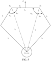
- the joint angle information is an angle between the first wheel leg and the base. As shown in FIG. 5 , the joint angle information includes joint angle ⁇ 11 , , joint angle ⁇ 12 , joint angle ⁇ 21 , and joint angle ⁇ 22 .
- the controller obtains, based on the joint angle information, the target joint torque ⁇ 1 of the motor associated with the first wheel leg at the current moment.
- l 5 and l 6 represent the distances between the connection points of the two leg structures of the first wheel leg and the base, respectively; l 1 and l 3 represent the sizes of the thigh structures in the two leg structures, respectively; and l 2 and l 4 represent the sizes of the lower leg structures in the two leg structures.
- the wheel-legged robot adjusts an angle between the auxiliary wheel leg and the base by controlling the motor associated with the auxiliary wheel leg, that is, the third motor 170 in FIG. 2 , thereby controlling the projection point of the center of mass of the wheel-legged robot on the stair to be within the triangular range formed by the stair contact points of the three wheel legs.
- the wheel-legged robot first controls the wheel-legged robot to move forwards on the first stair to make the first wheel leg and the second wheel leg move to a junction between the first stair and the second stair, and then controls the base of the wheel-legged robot to move downwards.
- the first wheel leg and the second wheel leg By making the first wheel leg and the second wheel leg to the junction between the first stair and the second stair, a distance that the first wheel leg and the second wheel leg need to move to go upstairs is reduced, so that the wheel-legged robot can better complete the action of going upstairs.
- the wheel-legged robot obtains distance between the wheels of both the first wheel leg and the second wheel leg and a stair junction, and obtains reference rotational speed of the two wheels; obtains, based on the obtained distance and the reference rotational speeds, torques for controlling the two wheels; and controls the motors of the two wheels based on the torques of the two wheels, that is, controls the two second motors 160 in FIG. 2 , so that the two wheels rotate, and the wheel-legged robot moves forwards on the first stair.
- the wheel-legged robot randomly determines the reference rotational speeds of the two wheels, or a skilled person sends to the wheel-legged robot a control command for a moving speed of the robot through a control device.
- the wheel-legged robot receives the control command and obtains the reference rotational speeds of the two wheels based on radiuses of the two wheels and the moving speed carried in the control command.
- FIG. 6 shows images and three-dimensional views of the wheel-legged robot on the first stair in three viewing angles.
- the wheel-legged robot keeps balance on the first stair through the three wheel legs.
- the first wheel leg 601 and the second wheel leg 602 are located at the stair junction.
- the auxiliary wheel leg 603 is located on the first stair.
- a projection point 604 of a center of mass of the wheel-legged robot on the stair is within a triangle composed of stair contact points of the three wheel legs.
- the wheel-legged robot controls the first wheel leg to move from the first stair onto the second stair, while controlling the second wheel leg and the auxiliary wheel leg to remain in their positions on the first stair, wherein the first stair and the second stair have different stair heights.
- the process of controlling the first wheel leg to move to the second stair includes the following:
- the wheel-legged robot first controls the first wheel leg to be lifted and then controls, within a time period when the first wheel leg leaves the first stair and does not contact the second stair, the first wheel leg to move towards the second stair, so that the first wheel leg moves onto the second stair in a case of falling.
- the above process will be explained below through stair 402A to step 402B.
- the wheel-legged robot controls the first wheel leg to jump up to make the first wheel leg leave the first stair.
- the wheel-legged robot obtains, based on the height difference between the first stair and the second stair and a wheel leg moving direction, a target joint torque ⁇ 3 of a motor associated with the first wheel leg, that is, obtains the target j oint torque ⁇ 3 of the two first motors 150 associated with the first wheel leg in FIG. 2 , and controls, based on the target joint torque ⁇ 3 , the first wheel leg to pedal on the first stair to lift up the first wheel leg based on a reacting force of the first stair.
- the wheel leg moving direction is indicated by the jump up action, for example the upward direction.
- a data form of the target joint torque ⁇ 3 is similar to that of the target joint torque ⁇ 1 in step 401, and will not be repeatedly described.
- the controller obtains, based on the height difference between the first stair and the second stair, a first angle at which one side, connected to the first wheel leg, of the base to be lifted; determines, based on the first angle, an initial acceleration of the first wheel leg for leaving the first stair and a reacting force to the first wheel leg for leaving the first stair; and obtains, based on the initial acceleration, the reacting force, and the wheel leg moving direction, the target joint torque ⁇ 3 of the motor associated with the first wheel leg.
- the controller determines, based on the first angle, a height ⁇ l at which the first wheel leg needs to be lifted using formula (3), and determines the initial acceleration and the reacting force based on the height at which the first wheel leg needs to be lifted.
- ⁇ l l 0 tan ⁇ ref
- l 0 represents a distance between the wheels of both the first wheel leg and the second wheel leg
- ⁇ ref represents the first angle.
- the wheel-legged robot controls, when the first wheel leg leaves the first stair, the first wheel leg to move towards the second stair, so that the first wheel leg moves onto the second stair when falling on the second stair.
- the wheel-legged robot obtains, based on the first distance and a wheel leg moving direction indicated by the retraction action (for example a upward direction ), a first joint torque of the motor associated with the first wheel leg, that is, obtains the first joint torque of the two first motors 150 associated with the first wheel leg in FIG. 2 , and controls, based on the first joint torque, the first wheel leg to retract the first distance.
- a wheel leg moving direction indicated by the retraction action for example a upward direction
- the wheel-legged robot determines, based on the second distance and a wheel leg moving direction indicated by the swing towards the second stair, a second joint torque of the motor associated with the first wheel leg, that is, obtains the second joint torque of the two first motors 150 associated with the first wheel leg in FIG. 2 , and controls, based on the second joint torque, the first wheel leg to rotate, to make an end of the first wheel leg move the second distance towards the second stair.
- the process of obtaining the first joint torque based on the first distance and the process of obtaining the second joint torque based on the second distance are the same as the process corresponding to FIG. 5 in step 401, and will not be repeatedly described here.
- Data forms of the first j oint torque and the second j oint torque are the same as that of the target j oint torque ⁇ 1 in step 401, and will not be repeatedly described here.
- a projection point 804 of a center of mass of the wheel-legged robot on a horizontal plane is within a projection area of a triangular range composed of the stair contact points of the three wheel legs on the horizontal plane, so that the wheel-legged robot can be kept balance.
- the wheel-legged robot controls the base of the wheel-legged robot to move towards the second stair to make a projection point of a center of mass of the wheel-legged robot move from the first stair to the second stair.
- the wheel-legged robot determines, based on a current position of the center of mass of the wheel-legged robot, a distance that the base needs to move towards the second stair; obtains, based on a distance that the base needs to move towards the second stair, a joint torque for controlling the base to move; and controls the two first motors 150 of the first wheel leg and the two first motors 150 of the second wheel leg in FIG. 2 based on the obtained joint torque, so that the base moves towards the second stair while the wheels of both the first wheel leg and the second wheel leg remain stationary.
- a data format of the joint torque for controlling the first wheel leg and a data format of the joint torque for controlling the second wheel leg are the same as that of the target joint torque ⁇ 1 in step 401, and will not be repeatedly described here.
- FIG. 9 shows images and three-dimensional views of the wheel-legged robot in the moving process of the base in three viewing angles.
- Solid lines and dashed lines in FIG. 9 are respectively used to represent postures of the wheel-legged robot before and after the base moves.
- the base 905 of the wheel-legged robot is controlled to move towards the second stair.
- a projection point 904 of a center of mass of the wheel-legged robot on the stair moves to the second stair.
- the auxiliary wheel leg 903 moves towards the second stair along with the movement of the base.
- the wheel-legged robot controls the second wheel leg to move from the first stair onto the second stair, while controlling the first wheel leg to remain in its position on the second stair, and controlling the auxiliary wheel leg to remain in its position on the first stair.
- the wheel-legged robot controls, based on the method that is the same as step 402, the second wheel leg to move to the second stair, which will not be repeatedly described.
- FIG. 10 shows images and three-dimensional views of the wheel-legged robot in the moving process of the second wheel leg in three viewing angles.
- Solid lines and dashed lines in FIG. 10 are respectively used to represent postures of the wheel-legged robot before and after the first wheel leg moves.
- the wheel-legged robot controls the first wheel leg 1002 to downwards pedal on the ground and controls, within a time period when the second wheel leg does not contact the stair, the second wheel leg to retract and swing towards the second stair, so that the second wheel leg moves onto the second stair in case of falling.
- the first wheel leg 1001 is controlled to remain in its position on the second stair
- the auxiliary wheel leg 1003 is controlled to remain in its position on the first stair.
- a projection point 1004 of a center of mass of the wheel-legged robot on a horizontal plane is within a projection area on the horizontal plane of a triangular range composed of the stair contact points of the three wheel legs.
- the wheel-legged robot controls the base of the wheel-legged robot to move forwards to make a projection point of a center of mass of the wheel-legged robot on the second stair move to a first position, the first position being as follows: a distance from the first position to a connecting line between a step contact point of the first wheel leg and a step contact point of the second wheel leg is less than a distance threshold, and the first position is within a triangular range composed of the stair contact point of the first wheel leg, the stair contact point of the second wheel leg, and a stair contact point of the auxiliary wheel leg.
- the wheel-legged robot controls, based on the method that is the same as stair 403, the base to move forwards, which will not be repeatedly described. Since the projection point of the center of mass of the wheel-legged robot on the stair moves to the first position, the center of mass of the wheel-legged robot further moves forwards. Thus, in the subsequent steps, the difficulty of keeping balance of the wheel-legged robot on the second stair by the two wheel legs is lowered, and the wheel-legged robot can better complete the action of going upstairs.
- the auxiliary wheel leg moves forwards on the first stair along with the movement of the base.
- FIG. 11 shows images and three-dimensional views of the wheel-legged robot in the moving process of the base in three viewing angles.
- Solid lines and dashed lines in FIG. 11 are respectively used to represent postures of the wheel-legged robot before and after the base moves.
- the wheel-legged robot controls the base 1105 to move forwards.
- a projection point 1104 of a center of mass of the wheel-legged robot on the stair moves to the target position.
- the auxiliary wheel leg 1103 moves forwards on the first stair along with the movement of the base.
- the wheel-legged robot first controls the wheel-legged robot to move forwards a target distance on the second stair.
- the target distance is less than a distance between the stair contact point of the second wheel leg and a junction of the second stair and a third stair.
- the second stair and the third stair have different stair heights.
- the wheel-legged robot then controls the base to move forwards, so that a projection point of a center of mass of the wheel-legged robot moves to the first position.
- the wheel-legged robot By controlling the wheel-legged robot to move forwards the target distance, the distance between the first wheel leg and the junction of the first stair and the second stair, as well as the distance between the second wheel leg and the junction are increased, which can avoid a situation that the wheel-legged robot falls back from the second stair to the first stair when it keeps balance through the first wheel leg and the second wheel leg in the subsequent steps, so that the wheel-legged robot can better complete the action of going upstairs.
- the wheel-legged robot controls the wheel-legged robot to keep balance on the second stair by taking the first wheel leg and the second wheel leg as supports.
- the wheel-legged robot taking the first wheel leg and the second wheel leg as the supports keeps balance by controlling three space angles of the wheel-legged robot.
- the three space angles are a pitch angle, a roll angle, and a yaw angle.
- FIG. 12 is a schematic diagram of a space angle provided by this application.
- FIG. 12 shows a right hand side cartesian coordinate system built based on a center of the base, where an X-axis is a coordinate axis along a forwarding direction of the wheel-legged robot, corresponding to the roll angle. That is, an angle of the wheel-legged robot in an X-axis direction is referred to as the roll angle.
- a Y-axis is a coordinate axis in a two-wheel connecting direction of the wheel-legged robot, corresponding to the pitch angle. That is, an angle in a Y-axis direction of the wheel-legged robot is referred to as the pitch angle.
- a Z-axis is a coordinate axis in a vertically upward direction, corresponding to the yaw angle. That is, an angle in a Z-axis direction of the wheel-legged robot is referred to as the yaw angle.
- the wheel-legged robot first obtains reference moving speeds ⁇ ref and current moving speeds ⁇ of centers of the wheels of both the first wheel leg and the second wheel leg.
- the reference moving speed is a moving speed that the center of the wheel needs to achieve based on a motion state of the wheel-legged robot. For example, if the wheel-legged robot needs to remain stationary in a balanced state, the reference moving speed is 0.
- the wheel-legged robot inputs a difference value between ⁇ ref and ⁇ to a Proportional-integral-differential (PID) controller 1301 to obtain a reference pitch angle ⁇ ref of the wheel-legged robot.
- PID Proportional-integral-differential
- the wheel-legged robot then obtains a current pitch angle ⁇ of the wheel-legged robot and inputs a difference value between ⁇ ref and ⁇ to a PID controller 1302 to obtain a reference pitch angle speed ⁇ ref .
- the wheel-legged robot obtains a current pitch angle speed ⁇ of the wheel-legged robot and inputs a difference value between ⁇ ref and ⁇ to a PID controller 1303 to obtain a torque for controlling pitch angle balance.
- the second motors of the two wheels are controlled based on the obtained torque, thereby controlling pitch angle balance of the wheel-legged robot.
- ⁇ ⁇ , and ⁇ are obtained based on a posture sensor of the wheel-legged robot.
- the wheel-legged robot obtains a reference roll angle ⁇ ref ' and a current roll angle ⁇ of the wheel-legged robot.
- the wheel-legged robot obtains the reference roll angle as 0°.
- the roll angle carried in the roll angle control command is obtained as the reference roll angle.
- the wheel-legged robot obtains the current roll angle based on a posture sensor.
- the wheel-legged robot inputs a difference value between ⁇ ref ' and ⁇ to a PID controller 1401 to obtain a distance ⁇ l' that the first wheel leg and the second wheel leg need to extend and retract, and inputs ⁇ l' to an inverse kinematics solver (IK) 1402 to obtain joint angle information of the first wheel leg and the second wheel leg.
- IK inverse kinematics solver
- a torque for controlling roll angle balance is obtained based on the joint angle information.
- the two first motors of the first wheel leg and the two first motors of the second wheel leg are controlled based on the obtained torque, thereby controlling roll angle balance of the wheel-legged robot.
- a data format of the torque for controlling the first wheel leg and a data format of the torque for controlling the second wheel leg are the same as that of the target joint torque ⁇ 1 in step 401, and will not be repeatedly described here.
- the wheel-legged robot obtains a reference yaw angle ⁇ ref and a current yaw angle ⁇ of the wheel-legged robot.
- the wheel-legged robot obtains the reference yaw angle as 0°.
- the yaw angle carried in the yaw angle control command is obtained as the reference yaw angle.
- the wheel-legged robot obtains the current roll angle based on a posture sensor.
- the wheel-legged robot obtains a reference moving speed ⁇ 1 of the center of the wheel of the first wheel leg and a reference moving speed ⁇ 2 of the center of the wheel of the second wheel leg based on a difference value between ⁇ ref and ⁇ ; obtains reference rotational speeds of the two wheels based on ⁇ 1 , ⁇ 2 , and radiuses of the wheels, obtains, based on the reference rotational speeds, a torque for controlling yaw angle balance of the two wheels, and controls the second motors of the two wheels based on the obtained torque, thereby controlling yaw angle balance of the wheel-legged robot.
- the wheel-legged robot After the wheel-legged robot keeps balance on the second stair by taking the first wheel leg and the second wheel leg as the supports, although the auxiliary wheel leg still contacts the first stair, an acting force between the auxiliary wheel leg and the first stair approaches 0, that is, the wheel-legged robot no longer keeps balance by taking the auxiliary wheel leg as the support, which lays a good foundation for moving the auxiliary wheel leg onto the second stair in the subsequent steps.
- the wheel-legged robot controls the auxiliary wheel leg to move from the first stair onto the second stair, and controls the first wheel leg and the second wheel leg to stay on the second stair.
- the process of controlling the auxiliary wheel leg to move onto the second stair includes the following.
- the wheel-legged robot controls the base of the wheel-legged robot to move upwards a third distance, the third distance being greater than or equal to the height difference between the first stair and the second stair; and controls the wheel-legged robot to move forwards on the second stair to make the auxiliary wheel leg connected to the base move onto the second stair.
- the wheel-legged robot records an initial height of the wheel-legged robot.
- the initial height is a distance between the base and the first stair when the wheel-legged robot keeps balance on the first stair by the three wheel legs.
- the third distance is also a height difference between a current height of the wheel-legged robot and the initial height of the wheel-legged robot. The third distance is obtained through the initial height, so that a height of the wheel-legged robot remains consistent with the initial height after the base moves upwards the third distance, so that the wheel-legged robot can better perform the action of going upstairs in the next time.
- the controller obtains, based on the third distance and a wheel leg moving direction indicated by the extension action, a third joint torque of the motor associated with the first wheel leg and a fourth j oint torque of the motor associated with the second wheel leg, that is, obtains the third joint torque of the two first motors 150 associated with the first wheel leg in FIG. 2 and the fourth joint torque of the two first motors 150 associated with the second wheel leg in FIG. 2 , and controls, based on the third joint torque and the fourth joint torque, the first wheel leg and the second wheel leg to extend the third distance to make the base move upwards the third distance.
- the process of obtaining the third joint torque and the fourth joint torque based on the third distance is the same as the process corresponding to FIG. 5 in step 401, and will not be repeatedly described here.
- Data forms of the third joint torque and the fourth joint torque are the same as that of the target joint torque ⁇ 1 in step 401, and will not be repeatedly described here.
- FIG. 15 shows images and three-dimensional views of the wheel-legged robot in the process that the base moves upwards the third distance in three viewing angles.
- the wheel-legged robot controls the base 1505 to move upwards the third distance, so that the auxiliary wheel leg 1503 leaves the first stair.
- the wheel-legged robot controls the first wheel leg 1501 and the second wheel leg 1502 to remain stable on the second stair.
- the posture of the wheel-legged robot changes, so that the position of the center of mass of the wheel-legged robot also changes.
- the wheel-legged robot obtains the position of the center of mass of the wheel-legged robot in real time, obtains, based on the position of the center of mass of the wheel-legged robot and the PID controller 1301, the PID controller 1302 and the PID controller 1303 in step 406, a torque for controlling pitch angle balance, and controls the second motors of the two wheels based on the obtained torque, thereby keeping the balance of the wheel-legged robot in a pitch angle direction.
- the first wheel leg, the second wheel leg, and the auxiliary wheel leg are controlled to move from the first stair to the second stair in sequence, and the other two wheel legs are controlled to remain in their positions on the stair when moving any wheel leg, so that in a case of ensuring the balance of the wheel-legged robot, the function of the wheel-legged robot for going upstairs is realized, the diversity of actions and functions of the wheel-legged robot is improved, and the adaptability of the wheel-legged robot to the ground is also improved.
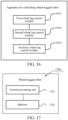
- FIG. 16 is a schematic structural diagram of an apparatus for controlling a wheel-legged robot provided according to an embodiment of this application. As shown in FIG. 16 , the apparatus includes: a first wheel leg control module 1601, a second wheel leg control module 1602, and an auxiliary wheel leg control module 1603.
- the first wheel leg control module 1601 is configured to: control the first wheel leg to move from a first stair onto a second stair, while controlling the second wheel leg and the auxiliary wheel leg to remain in their positions on the first stair, wherein the first stair and the second stair have different stair heights;
- the first wheel leg control module 1601 includes:
- the first control sub-module includes:
- the wheel-legged robot further includes a base; the base is located above the first wheel leg, the second wheel leg, and the auxiliary wheel leg and is connected to the first wheel leg, the second wheel leg, and the auxiliary wheel leg.
- the obtaining unit is configured to obtain, based on the height difference, a first angle at which one side, connected to the first wheel leg, of the base to be lifted; determine, based on the first angle, an initial acceleration of the first wheel leg for leaving the first stair and a reacting force to the first wheel leg for leaving the first stair; and obtain, based on the initial acceleration, the reacting force, and the wheel leg moving direction, the target joint torque of the motor associated with the first wheel leg.
- the second control sub-module is configured to: control, when the first wheel leg leaves the first stair, the first wheel leg to retract a first distance, and control the first wheel leg to rotate, to make an end of the first wheel leg move a second distance towards the second stair.
- the first distance is greater than the height difference between the first stair and the second stair; and the second distance is greater than the radius of the wheel of the first wheel leg and less than a width of the second stair.
- the second control sub-module is configured to: obtain, based on the first distance and a wheel leg moving direction, a first joint torque of the motor associated with the first wheel leg; and control, based on the first joint torque, the first wheel leg to retract the first distance.
- the second control sub-module is configured to: determine, based on the second distance and a wheel leg moving direction towards the second stair, a second joint torque of the motor associated with the first wheel leg; and control, based on the second joint torque, the first wheel leg to rotate, to make the end of the first wheel leg move a second distance towards the second stair.
- the wheel-legged robot further includes a base; the base is located above the first wheel leg, the second wheel leg, and the auxiliary wheel leg and is connected to the first wheel leg, the second wheel leg, and the auxiliary wheel leg.
- the auxiliary wheel leg control module 1603 includes:
- the apparatus further includes: a first balance control module, configured to control the wheel-legged robot to keep balance on the first stair by taking the first wheel leg, the second wheel leg, and the auxiliary wheel leg as supports.
- the wheel-legged robot further includes a base; the base is located above the first wheel leg, the second wheel leg, and the auxiliary wheel leg and is connected to the first wheel leg, the second wheel leg, and the auxiliary wheel leg.
- the first balance control module is further configured to control the wheel-legged robot to move forwards on the first stair to make the first wheel leg and the second wheel leg move to a junction between the first stair and the second stair.
- the wheel-legged robot further includes a base; the base is located above the first wheel leg, the second wheel leg, and the auxiliary wheel leg and is connected to the first wheel leg, the second wheel leg, and the auxiliary wheel leg.
- the apparatus further includes: a base control module, configured to control the base of the wheel-legged robot to move towards the second stair to make a projection point of a center of mass of the wheel-legged robot move from the first stair to the second stair.
- a base control module configured to control the base of the wheel-legged robot to move towards the second stair to make a projection point of a center of mass of the wheel-legged robot move from the first stair to the second stair.
- the apparatus further includes: a second balance control module, configured to control the wheel-legged robot to keep balance on the second stair by taking the first wheel leg and the second wheel leg as supports.
- the wheel-legged robot further includes a base; the base is located above the first wheel leg, the second wheel leg, and the auxiliary wheel leg and is connected to the first wheel leg, the second wheel leg, and the auxiliary wheel leg.
- the apparatus further includes: a base control module, configured to control the base of the wheel-legged robot to move forwards to make a projection point of a center of mass of the wheel-legged robot on the second stair move to a first position, the first position being as follows: a distance from the first position to a connecting line between a step contact point of the first wheel leg and a step contact point of the second wheel leg is less than a distance threshold, and the first position is within a triangular range composed of the stair contact point of the first wheel leg, the stair contact point of the second wheel leg, and a stair contact point of the auxiliary wheel leg.
- a base control module configured to control the base of the wheel-legged robot to move forwards to make a projection point of a center of mass of the wheel-legged robot on the second stair move to a first position, the first position being as follows: a distance from the first position to a connecting line between a step contact point of the first wheel leg and a step contact point of the second wheel leg is less
- the apparatus for controlling the wheel-legged robot provided according to the above embodiments controls the wheel-legged robot
- only an example of division of the foregoing functional modules is described.
- the foregoing functions are allocated to and completed by different functional modules as required, that is, an inner structure of the apparatus is divided into different functional modules, so as to complete all or some of the functions described above.
- the apparatus for controlling the wheel-legged robot provided in the above embodiments and the method for controlling the wheel-legged robot provided in the above embodiments belong to the same concept. For the specific implementation process, refer to the method embodiments, and details are not described here again.
- FIG. 17 is a schematic structural diagram of a wheel-legged robot provided according to an embodiment of this application.
- the wheel-legged robot 1700 may vary a lot due to different configurations or performance, and may include one or more central processing units (CPUs) 1701 and one or more memories 1702.
- the one or more memories 1702 store at least one program code, and the at least one program code is loaded and executed by the one or more CPUs 1701 to implement the methods provided in all the above method embodiments.
- the wheel-legged robot 1700 may further include components such as a wired or wireless network interface, a keyboard, and an input/output interface, to facilitate inputting and outputting.
- the wheel-legged robot 1700 may further include another component configured to implement a function of a device. Details are not repeatedly described here.
- a computer-readable storage medium such as a memory including at least one program code, and the at least one program code may be executed by a CPU to complete the method for controlling the wheel-legged robot in the above embodiments.
- the computer-readable storage medium may be a read-only memory (ROM), a Random Access Memory (RAM), a compact disc ROM (CD-ROM), a magnetic tape, a floppy disk, an optical data storage device, or the like.
- the computer program In all embodiments of the present disclosure may be deployed on a computer device for execution, or on a plurality of computer devices located at one site for execution, or on a plurality of computer devices distributed at a plurality of sites and interconnected by a communication network for execution, and the plurality of computer devices distributed at the plurality of sites and interconnected by the communication network form a blockchain system.
- Information including but not limited to user device information and user personal information
- data including but not limited to data for analysis, stored data, displayed data, and the like
- signals involved in this application are authorized by a user or fully authorized by all parties, and the acquisition, use, and processing of the relevant data need to comply with relevant laws, regulations, and standards of relevant countries and regions. For example, stair information involved in this application is obtained under full authorization.
- the program is stored in a computer-readable storage medium.
- the storage medium includes a read-only memory, a magnetic disk, an optical disc, or the like.
Landscapes
- Engineering & Computer Science (AREA)
- Mechanical Engineering (AREA)
- Robotics (AREA)
- Human Computer Interaction (AREA)
- Chemical & Material Sciences (AREA)
- Combustion & Propulsion (AREA)
- Transportation (AREA)
- Radar, Positioning & Navigation (AREA)
- Aviation & Aerospace Engineering (AREA)
- Remote Sensing (AREA)
- Physics & Mathematics (AREA)
- General Physics & Mathematics (AREA)
- Automation & Control Theory (AREA)
- Manipulator (AREA)
- Toys (AREA)
- Control Of Position, Course, Altitude, Or Attitude Of Moving Bodies (AREA)
Abstract
Description
- This application claims priority to
Chinese Patent Application 202210238633.0, entitled "METHOD AND APPARATUS FOR CONTROLLING WHEEL-LEGGED ROBOT, ROBOT, AND STORAGE MEDIUM" filed with the China National Intellectual Property Administration on March 11, 2022 - Embodiments of this application relate to the field of robots, and in particular, to a method and apparatus for controlling a wheel-legged robot, a robot, and a storage medium.
- A wheel-legged robot is a robot that controls the motion of a robot main body through a wheel-legged structure. The agility and flexibility of the wheel-legged robot in ground motion have attracted widespread attention of researchers. How to control the wheel-legged robot to achieve more actions is currently a main research direction.
- Embodiments of this application provide a method and apparatus for controlling a wheel-legged robot, a robot, and a storage medium.
- One aspect provides a method for controlling a wheel-legged robot, the wheel-legged robot including a first wheel leg, a second wheel leg, and an auxiliary wheel leg, and the method including: controlling the first wheel leg to move from a first stair onto a second stair, while controlling the second wheel leg and the auxiliary wheel leg to remain in their positions on the first stair, wherein the first stair and the second stair have different stair heights; controlling the second wheel leg to move from the first stair onto the second stair, controlling the first wheel leg to remain in its position on the second stair, and controlling the auxiliary wheel leg to remain in its position on the first stair; and controlling the auxiliary wheel leg to move from the first stair onto the second stair, and controlling the first wheel leg and the second wheel leg to stay on the second stair.
- One aspect provides an apparatus for controlling a wheel-legged robot, the wheel-legged robot including a first wheel leg, a second wheel leg, and an auxiliary wheel leg, and the apparatus including: a first wheel leg control module, configured to: control the first wheel leg to move from a first stair onto a second stair, while controlling the second wheel leg and the auxiliary wheel leg to remain in their positions on the first stair, wherein the first stair and the second stair have different stair heights; a second wheel leg control module, configured to: control the second wheel leg to move from the first stair onto the second stair, while controlling the first wheel leg to remain in its position on the second stair, and controlling the auxiliary wheel leg to remain in its position on the first stair; and an auxiliary wheel leg control module, configured to: control the auxiliary wheel leg to move from the first stair onto the second stair, while controlling the first wheel leg and the second wheel leg to stay on the second stair.
- One aspect provides a wheel-legged robot, the wheel-legged robot including a first wheel leg, a second wheel leg, an auxiliary wheel leg, a base, one or more central processing units, and one or more memories, the base being located above the first wheel leg, the second wheel leg, and the auxiliary wheel leg and being connected to the first wheel leg, the second wheel leg, and the auxiliary wheel leg; the one or more memories storing at least one computer program; and the at least one computer program being loaded and executed by the one or more central processing units to implement the method for controlling the wheel-legged robot.
- One aspect provides a computer-readable storage medium, the computer-readable storage medium storing at least one computer program, and the at least one computer program being loaded and executed by a central processing unit to implement the method for controlling the wheel-legged robot.
- One aspect provides a computer program product, the computer program product including at least one computer program, and the at least one computer program being stored in a computer-readable storage medium. A central processing unit of a wheel-legged robot reads the at least one computer program from the computer-readable storage medium, and the central processing unit executes the at least one computer program, causing the wheel-legged robot to implement the method for controlling the wheel-legged robot.
-
-
FIG. 1 is a schematic diagram of an implementation environment of a method for controlling a wheel-legged robot provided according to an embodiment of this application. -
FIG. 2 is a schematic structural diagram of a wheel-legged robot provided according to an embodiment of this application. -
FIG. 3 is a flowchart of a method for controlling a wheel-legged robot provided according to an embodiment of this application. -
FIG. 4 is a flowchart of a method for controlling a wheel-legged robot provided according to an embodiment of this application. -
FIG. 5 is a schematic diagram of obtaining joint angle information provided according to an embodiment of this application. -
FIG. 6 is a schematic diagram of a posture of a wheel-legged robot on a first stair provided according to an embodiment of this application. -
FIG. 7 is a schematic diagram of a lifting height of a wheel leg provided according to an embodiment of this application. -
FIG. 8 is a schematic diagram of moving a first wheel leg provided according to an embodiment of this application. -
FIG. 9 is a schematic diagram of moving a base provided according to an embodiment of this application. -
FIG. 10 is a schematic diagram of moving a second wheel leg provided according to an embodiment of this application. -
FIG. 11 is a schematic diagram of moving a base provided according to an embodiment of this application. -
FIG. 12 is a schematic diagram of a space angle provided according to an embodiment of this application. -
FIG. 13 is a schematic diagram of controlling a pitch angle to be balanced provided according to an embodiment of this application. -
FIG. 14 is a schematic diagram of controlling a roll angle to be balanced provided according to an embodiment of this application. -
FIG. 15 is a schematic diagram of moving a base provided according to an embodiment of this application. -
FIG. 16 is a schematic structural diagram of an apparatus for controlling a wheel-legged robot provided according to an embodiment of this application; and -
FIG. 17 is a schematic structural diagram of a wheel-legged robot provided according to an embodiment of this application. - To make the objectives, technical solutions, and advantages of this application clearer, the following further describes implementations of this application in detail with reference to the accompanying drawings.
- The terms "first", "second", and the like used in this application are used for distinguishing identical or similar items that have essentially the same effects and functions. It should be understood that there is no logical or temporal dependency relationship between "first", "second", and "nth", and there is no limitation on quantities and execution orders.
- The solutions provided in this application mainly involve a robot technology. A robot is a mechanical and electronic device that is a combination of mechanical transmission and a modern microelectronics technology to imitate a certain skill of a person. With the development of the technology, robots have been greatly improved in terms of functionality and technical level. Mobile robots and visual and tactile technologies of the robots are typical representatives.
- Wheel-legged robot: A wheel-legged robot is a robot that controls the motion of the robot through a wheel-legged structure. It has extremely high wheel energy and extremely strong adaptability and can adapt to uneven terrains. The wheel-legged structure includes two parts: a leg containing at least one j oint; and a wheel. Due to the fact that wheel-legged robots only contact the ground through wheels of their wheel legs, there is often a problem of balance control.
- The following describes an implementation environment of this application.
FIG. 1 is a schematic diagram of an implementation environment of a method for controlling a wheel-legged robot provided in the embodiments of this application. Referring toFIG. 1 , the implementation environment includes a wheel-leggedrobot 100 and acontrol device 200. The wheel-leggedrobot 100 and thecontrol device 200 are connected to each other through a wired or wireless network. - In the embodiments of the present disclosure including the embodiments of both the claims and the specification (hereinafter referred to as "all embodiments of the present disclosure")In all embodiments of the present disclosure, the structure of the wheel-
legged robot 100 is as shown inFIG. 2 . The wheel-leggedrobot 100 includes afirst wheel leg 110, asecond wheel leg 120, anauxiliary wheel leg 130, and abase 140. Thebase 140 is located above thefirst wheel leg 110, thesecond wheel leg 120, and theauxiliary wheel leg 130 and is connected to thefirst wheel leg 110, thesecond wheel leg 120, and theauxiliary wheel leg 130. - The
first wheel leg 110 and thesecond wheel leg 120 are configured to drive the robot to move. The structure of thefirst wheel leg 110 and the structure of thesecond wheel leg 120 are the same. An explanation will be made below by taking thefirst wheel leg 110 as an example. As shown inFIG. 2 , thefirst wheel leg 110 includes twoleg structures 111 and awheel 112. The twoleg structures 111 are connected to thewheel 112. Each of the twoleg structures 111 includes a thigh structure 1111 and alower leg structure 1112, that is, thefirst wheel leg 110 includes two thigh structures 1111 and twolower leg structures 1112. Each thigh structure 1111 and one matchinglower leg structure 1112 are connected through a rotational joint. Each of the twoleg structures 111 is associated with onefirst motor 150, and eachfirst motor 150 is connected to the thigh structure 1111 in the associatedleg structure 111 and is configured to control the associatedleg structure 111 to extend and retract. That is, thefirst wheel leg 110 is controlled by the twofirst motors 150, and the two thigh structures 1111 of thefirst wheel leg 110 are respectively connected to thebase 140 through output shafts of the respective associatedfirst motors 150. Thewheel 112 is a driving wheel. Thewheel 112 can be driven by asecond motor 160 to actively rotate, thereby controlling the wheel-leggedrobot 100 to perform designated actions, such as: controlling the wheel-legged robot to move forwards, controlling the wheel-legged robot to move backwards, controlling the wheel-legged robot to turn, controlling the wheel-legged robot to stand still, or the like. For example, thesecond motor 160 is fixed on onelower leg structure 1112 of thefirst wheel leg 110 to drive a rotating shaft of the wheel 112 (namely, the driving wheel) through belt transmission, to drive the driving wheel. - The
auxiliary wheel leg 130 is configured to assist the wheel-legged robot in maintaining balance, so that the wheel-legged robot can complete complex actions such as going upstairs. As shown inFIG. 2 , theauxiliary wheel leg 130 includes anauxiliary wheel leg 131 and anauxiliary wheel 132. Theauxiliary wheel leg 131 is connected to the base 140 through an output shaft of athird motor 170. Thethird motor 170 is configured to control theauxiliary wheel leg 130 to swing up and down relative to the base. Theauxiliary wheel 132 is a driven wheel. In a case that theauxiliary wheel leg 130 contacts the ground, theauxiliary wheel 132 can roll on the ground as the wheel-legged robot 100 moves. - The wheel-
legged robot 100 also includes hardware structures such as a central processing unit and a battery. Optionally, the central processing unit and the battery are mounted in thebase 140. The central processing unit is configured to control the wheel-legged robot to perform various actions. Optionally, the central processing unit is an independent hardware structure, or the wheel-legged robot includes a microcomputer. The central processing unit is integrated into the microcomputer. - The
control device 200 is a terminal or a remote controller. The terminal includes a smartphone, a tablet, a laptop, a desktop computer, and the like. The embodiments of this application do not limit this. In all embodiments of the present disclosure, thecontrol device 200 is configured to send a control command to the wheel-legged robot 100 to control the wheel-legged robot 100 to perform actions indicated by the control command. - Based on the implementation environment shown in
FIG. 1 ,FIG. 3 is a flowchart of a method for controlling a wheel-legged robot provided according to an embodiment of this application. The method is performed by a central processing unit of the wheel-legged robot. As shown inFIG. 3 , this embodiment includes the following steps. - 301: The wheel-legged robot controls the first wheel leg to move from a first stair onto a second stair, while controlling the second wheel leg and the auxiliary wheel leg to remain in their positions on the first stair, the first stair and the second stair have different stair heights. A stair height indicates the height of a stair. A height of a stair may be the height of the horizontal surface of the stair. The stair height of the first stair is higher or lower than that of the second stair. In embodiments of the present disclosure, the wheel-legged robot controls the first wheel leg to perform a second step following a first step, while controlling the second wheel leg and the auxiliary wheel leg to remain in their positions after performing the first step. The first step is a step for moving onto the first stair, and the first second is a step for moving onto the second stair, the positions of the first wheel leg, the second wheel leg and the auxiliary wheel on a stair indicate the positions of the contact points with the stair (also be referred to as stair contact points) of the first wheel leg, the second wheel leg and the auxiliary wheel.
- In all embodiments of the present disclosure, the second stair is higher than the first stair. That is, the process that the first wheel leg moves from the first stair to the second stair is a process that the wheel-legged robot performs an action of going upstairs.
- In all embodiments of the present disclosure, the central processing unit first controls the wheel-legged robot to keep balance on the first stair by taking the above three wheel legs as supports, and then controls one wheel leg to move and the other two wheel legs to remain stationary, so that the wheel-legged robot can keep balance in the process that the wheel-legged robot performs the action of going upstairs.
- 302: The wheel-legged robot controls the second wheel leg to move from the first stair onto the second stair, while controlling the first wheel leg to remain in its position on the second stair, and controlling the auxiliary wheel leg to remain in its position on the first stair. In embodiments of the present disclosure, the wheel-legged robot controls the second wheel leg to perform a second step following a first step, while controlling the first wheel leg to remain in its position after performing the second step, and controlling the auxiliary wheel leg to remain in its position after performing the first step.
- 303: The wheel-legged robot controls the auxiliary wheel leg to move from the first stair onto the second stair, while controlling the first wheel leg and the second wheel leg to stay on the second stair. In embodiments of the present disclosure, controls the auxiliary wheel leg to perform a second step following a first step, while controlling the first wheel leg and the second wheel leg to stay on the second stair after performing the second step.
- In all embodiments of the present disclosure, for
steps 301 to 303 above, the wheel-legged robot controls the above three wheel legs based on stair information, so as to control the wheel-legged robot to perform the action of going upstairs. The stair information is used for describing features of the stairs and a position of the wheel-legged robot relative to the stairs, and includes widths of the stairs, the height difference between the first stair and the second stair, a distance between the wheel-legged robot and the first stair or the second stair, and the like. - Optionally, the wheel-legged robot obtains the stair information in two ways. In one implementation, a skilled person sends a control command to the wheel-legged robot through the control device. The control command carries the stair information. The central processing unit of the wheel-legged robot receives the control command and obtains the stair information carried by the control command. In another implementation, the wheel-legged robot is provided with an image acquisition sensor. The image acquisition sensor may acquire an image containing the first stair and the second stair. The wheel-legged robot acquires the stair information based on the image acquired by the image acquisition sensor.
- According to the technical solutions provided by the embodiments of this application, the first wheel leg, the second wheel leg, and the auxiliary wheel leg are controlled to move from the first stair to the second stair in sequence, and the other two wheel legs are controlled to remain in their positions on the stair when moving any wheel leg, so that in a case of ensuring the balance of the wheel-legged robot, the function of the wheel-legged robot for going upstairs is realized, the diversity of actions and functions of the wheel-legged robot is improved, and the adaptability of the wheel-legged robot to the ground is also improved.
- The embodiments provided in
FIG. 3 above briefly describe the method for controlling the wheel-legged robot provided in this application. Based on the implementation environment shown inFIG. 1 and the wheel-legged robot described inFIG. 2 , the method will be described in detail below in conjunction withFIG. 4. FIG. 4 is a flowchart of a method for controlling a wheel-legged robot provided according to an embodiment of this application. The embodiments of this application are explained by taking the following as an example: the wheel-legged robot obtains stair information based on an image acquisition sensor. As shown inFIG. 4 , the method is performed by the wheel-legged robot, and includes the following steps. - 401: The wheel-legged robot controls the wheel-legged robot to keep balance on the first stair by taking the first wheel leg, the second wheel leg, and the auxiliary wheel leg as supports.
- Optionally, the wheel-legged robot controls the first wheel leg, the second wheel leg, and the auxiliary wheel leg to remain stationary on the first stair, or adjusts the first wheel leg, the second wheel leg, and the auxiliary wheel leg to a stable state. The process of adjusting the three wheel legs to the stable state will be described below.
- In all embodiments of the present disclosure, the wheel-legged robot controls the base of the wheel-legged robot to move downwards, so that the auxiliary wheel leg connected to the base contacts the first stair, and controls a projection point of a center of mass of the wheel-legged robot on the first stair to be within a triangular range composed of a stair contact point of the first wheel leg, a stair contact point of the second wheel leg, and a stair contact point of the auxiliary wheel leg.
- Exemplarily, the process of controlling the base to move downwards will be explained. The wheel-legged robot obtains a distance between the auxiliary wheel leg and the first stair based on the image sent by the image acquisition sensor; obtains, based on the distance between the auxiliary wheel leg and the first stair and a wheel leg moving direction indicated by a retraction action, a target joint torque τ1 of a motor associated with the first wheel leg and a target joint torque τ2 of a motor associated with the second wheel leg, that is, obtains the target joint torque τ1 of the two
first motors 150 associated with the first wheel leg inFIG. 2 and the target joint torque τ2 of the twofirst motors 150 associated with the second wheel leg; and controls, based on the target joint torque τ1 , the twofirst motors 150 associated with the first wheel leg and controls, based on the target joint torque τ2, the twofirst motors 150 associated with the second wheel leg, so as to control the first wheel leg and the second wheel leg to retract, thereby causing the base of the wheel-legged robot to move downwards. Optionally, the target joint torque τ1 is a vector including two torques. Each torque corresponds to one first motor of the first wheel leg, that is, each torque is used for controlling one first motor of the first wheel leg. The two torques are the same or different. The embodiments of this application do not limit the data form of the target joint torque τ1. A data form of the target j oint torque τ2 is similar to that of the target j oint torque τ1, and will not be repeatedly described. - Exemplarily, the process of obtaining the target j oint torque τ1 and the target joint torque τ2 is explained. The wheel-legged robot determines a target movement trajectory of the base based on the distance between the auxiliary wheel leg and the first stair. The target movement trajectory is used for describing a duration to the base to move downwards and a position of the base at each moment during the movement of the base. The wheel-legged robot obtains, based on the position of the base at each moment and the wheel leg moving direction indicated by the retraction action, the target joint torque τ1 of the motor associated with the first wheel leg at each moment and the target joint torque τ2 of the motor associated with the second wheel leg at each moment. The target j oint torque τ1 and the target j oint torque τ2 at any moment are used for controlling the wheel legs to retract, so that the base moves from the position of the previous moment to the position of the current moment. For example, obtaining the target joint torque τ1 of the motor associated with the first wheel leg at any moment is taken as an example. As shown in
FIG. 5 , a controller determines a position X3 (x 3,z 3) of the wheel of the first wheel leg in a robot coordinate system based on the position of the base at the current time. The robot coordinate system is an XZ coordinate system that takes the position of the base as an origin. The controller determines, based on distances


FIG. 5 , the joint angle information includes joint angle θ 11, , joint angle θ 12, joint angle θ 21, and joint angle θ 22. The controller obtains, based on the joint angle information, the target joint torque τ1 of the motor associated with the first wheel leg at the current moment.

- where l 5 and l 6 represent the distances between the connection points of the two leg structures of the first wheel leg and the base, respectively; l 1 and l 3 represent the sizes of the thigh structures in the two leg structures, respectively; and l 2 and l 4 represent the sizes of the lower leg structures in the two leg structures.
- Optionally, the wheel-legged robot adjusts an angle between the auxiliary wheel leg and the base by controlling the motor associated with the auxiliary wheel leg, that is, the
third motor 170 inFIG. 2 , thereby controlling the projection point of the center of mass of the wheel-legged robot on the stair to be within the triangular range formed by the stair contact points of the three wheel legs. - In all embodiments of the present disclosure, the wheel-legged robot first controls the wheel-legged robot to move forwards on the first stair to make the first wheel leg and the second wheel leg move to a junction between the first stair and the second stair, and then controls the base of the wheel-legged robot to move downwards. By making the first wheel leg and the second wheel leg to the junction between the first stair and the second stair, a distance that the first wheel leg and the second wheel leg need to move to go upstairs is reduced, so that the wheel-legged robot can better complete the action of going upstairs.
- Exemplarily, the process of controlling the wheel-legged robot to move forwards on the first stair will be explained. The wheel-legged robot obtains distance between the wheels of both the first wheel leg and the second wheel leg and a stair junction, and obtains reference rotational speed of the two wheels; obtains, based on the obtained distance and the reference rotational speeds, torques for controlling the two wheels; and controls the motors of the two wheels based on the torques of the two wheels, that is, controls the two
second motors 160 inFIG. 2 , so that the two wheels rotate, and the wheel-legged robot moves forwards on the first stair. Optionally, the wheel-legged robot randomly determines the reference rotational speeds of the two wheels, or a skilled person sends to the wheel-legged robot a control command for a moving speed of the robot through a control device. The wheel-legged robot receives the control command and obtains the reference rotational speeds of the two wheels based on radiuses of the two wheels and the moving speed carried in the control command. - Exemplarily,
FIG. 6 shows images and three-dimensional views of the wheel-legged robot on the first stair in three viewing angles. As shown inFIG. 6 , the wheel-legged robot keeps balance on the first stair through the three wheel legs. Thefirst wheel leg 601 and thesecond wheel leg 602 are located at the stair junction. Theauxiliary wheel leg 603 is located on the first stair. Aprojection point 604 of a center of mass of the wheel-legged robot on the stair is within a triangle composed of stair contact points of the three wheel legs. - 402: The wheel-legged robot controls the first wheel leg to move from the first stair onto the second stair, while controlling the second wheel leg and the auxiliary wheel leg to remain in their positions on the first stair, wherein the first stair and the second stair have different stair heights.
- In all embodiments of the present disclosure, the process of controlling the first wheel leg to move to the second stair includes the following: The wheel-legged robot first controls the first wheel leg to be lifted and then controls, within a time period when the first wheel leg leaves the first stair and does not contact the second stair, the first wheel leg to move towards the second stair, so that the first wheel leg moves onto the second stair in a case of falling. The above process will be explained below through stair 402A to step 402B.
- 402A: The wheel-legged robot controls the first wheel leg to jump up to make the first wheel leg leave the first stair.
- In all embodiments of the present disclosure, the wheel-legged robot obtains, based on the height difference between the first stair and the second stair and a wheel leg moving direction, a target joint torque τ3 of a motor associated with the first wheel leg, that is, obtains the target j oint torque τ3 of the two
first motors 150 associated with the first wheel leg inFIG. 2 , and controls, based on the target joint torque τ3, the first wheel leg to pedal on the first stair to lift up the first wheel leg based on a reacting force of the first stair. The wheel leg moving direction is indicated by the jump up action, for example the upward direction. A data form of the target joint torque τ3 is similar to that of the target joint torque τ1 instep 401, and will not be repeatedly described. - Exemplarily, the process of obtaining the target joint torque τ3 will be explained. The controller obtains, based on the height difference between the first stair and the second stair, a first angle at which one side, connected to the first wheel leg, of the base to be lifted; determines, based on the first angle, an initial acceleration of the first wheel leg for leaving the first stair and a reacting force to the first wheel leg for leaving the first stair; and obtains, based on the initial acceleration, the reacting force, and the wheel leg moving direction, the target joint torque τ3 of the motor associated with the first wheel leg.
- Exemplarily, the process of obtaining the initial acceleration and the reacting force based on the first angle will be explained. As shown in
FIG. 7 , the controller determines, based on the first angle, a height Δl at which the first wheel leg needs to be lifted using formula (3), and determines the initial acceleration and the reacting force based on the height at which the first wheel leg needs to be lifted.
where l 0 represents a distance between the wheels of both the first wheel leg and the second wheel leg, and ϕref represents the first angle. - 402B: The wheel-legged robot controls, when the first wheel leg leaves the first stair, the first wheel leg to move towards the second stair, so that the first wheel leg moves onto the second stair when falling on the second stair.
- In all embodiments of the present disclosure, within the time period when the first wheel leg leaves the first stair and does not contact the second stair, the wheel-legged robot controls the first wheel leg to retract a first distance and controls the first wheel leg to rotate, to make an end of the first wheel leg move a second distance towards the second stair (i.e., swing a second distance towards the second stair ), so that the first wheel leg moves onto the second stair. The first distance is greater than the height difference between the first stair and the second stair; and the second distance is greater than the radius of the wheel of the first wheel leg and less than a width of the second stair.
- Exemplarily, the process of controlling the first wheel leg to retract the first distance will be explained. The wheel-legged robot obtains, based on the first distance and a wheel leg moving direction indicated by the retraction action (for example a upward direction ), a first joint torque of the motor associated with the first wheel leg, that is, obtains the first joint torque of the two
first motors 150 associated with the first wheel leg inFIG. 2 , and controls, based on the first joint torque, the first wheel leg to retract the first distance. - Exemplarily, the process of controlling the first wheel leg to rotate, to make an end of the first wheel leg move the second distance towards the second stair will be explained. The wheel-legged robot determines, based on the second distance and a wheel leg moving direction indicated by the swing towards the second stair, a second joint torque of the motor associated with the first wheel leg, that is, obtains the second joint torque of the two
first motors 150 associated with the first wheel leg inFIG. 2 , and controls, based on the second joint torque, the first wheel leg to rotate, to make an end of the first wheel leg move the second distance towards the second stair. - The process of obtaining the first joint torque based on the first distance and the process of obtaining the second joint torque based on the second distance are the same as the process corresponding to
FIG. 5 instep 401, and will not be repeatedly described here. Data forms of the first j oint torque and the second j oint torque are the same as that of the target j oint torque τ1 instep 401, and will not be repeatedly described here. - Exemplarily,
FIG. 8 shows images and three-dimensional views of the wheel-legged robot in the moving process of the first wheel leg in three viewing angles. Solid lines and dashed lines inFIG. 8 are respectively used to represent postures of the wheel-legged robot before and after the first wheel leg moves. As shown inFIG. 8 , the wheel-legged robot first controls thefirst wheel leg 801 to pedal on the ground to lift up the first wheel leg and controls, when the first wheel leg does not contact the stair, the first wheel leg to retract and swing towards the second stair, so that the first wheel leg moves onto the second stair when falling on the second stair. In this process, thesecond wheel leg 802 and theauxiliary wheel leg 803 remain in their positions on the first stair. In other words, thesecond wheel leg 802 and the auxiliary wheel leg 803are kept being stabilized on the first stair. After the first wheel leg moves to the second stair, aprojection point 804 of a center of mass of the wheel-legged robot on a horizontal plane is within a projection area of a triangular range composed of the stair contact points of the three wheel legs on the horizontal plane, so that the wheel-legged robot can be kept balance. - 403: The wheel-legged robot controls the base of the wheel-legged robot to move towards the second stair to make a projection point of a center of mass of the wheel-legged robot move from the first stair to the second stair.
- In all embodiments of the present disclosure, the wheel-legged robot determines, based on a current position of the center of mass of the wheel-legged robot, a distance that the base needs to move towards the second stair; obtains, based on a distance that the base needs to move towards the second stair, a joint torque for controlling the base to move; and controls the two
first motors 150 of the first wheel leg and the twofirst motors 150 of the second wheel leg inFIG. 2 based on the obtained joint torque, so that the base moves towards the second stair while the wheels of both the first wheel leg and the second wheel leg remain stationary. By controlling the base to move towards the second stair, the center of mass of the wheel-legged robot moves to a position above the second stair, so that in the subsequent step of controlling the second wheel leg to move to the second stair, the wheel-legged robot can better keep balance, so as to better complete the action of going upstairs. A data format of the joint torque for controlling the first wheel leg and a data format of the joint torque for controlling the second wheel leg are the same as that of the target joint torque τ1 instep 401, and will not be repeatedly described here. - In the moving process of the base, the auxiliary wheel leg will move on the first stair towards the second stair along with the movement of the base. The wheel-legged robot always keeps the projection point of the center of mass of the wheel-legged robot on a horizontal plane is within a projection area of a triangular range composed of the stair contact points of the three wheel legs on the horizontal plane, so that the wheel-legged robot always keeps balance.
- Exemplarily,
FIG. 9 shows images and three-dimensional views of the wheel-legged robot in the moving process of the base in three viewing angles. Solid lines and dashed lines inFIG. 9 are respectively used to represent postures of the wheel-legged robot before and after the base moves. As shown inFIG. 9 , in a case that the wheels of both thefirst wheel leg 901 and thesecond wheel leg 902 remain stationary, thebase 905 of the wheel-legged robot is controlled to move towards the second stair. Thus, aprojection point 904 of a center of mass of the wheel-legged robot on the stair moves to the second stair. In this process, theauxiliary wheel leg 903 moves towards the second stair along with the movement of the base. - 404: The wheel-legged robot controls the second wheel leg to move from the first stair onto the second stair, while controlling the first wheel leg to remain in its position on the second stair, and controlling the auxiliary wheel leg to remain in its position on the first stair.
- In all embodiments of the present disclosure, the wheel-legged robot controls, based on the method that is the same as
step 402, the second wheel leg to move to the second stair, which will not be repeatedly described. - Exemplarily,
FIG. 10 shows images and three-dimensional views of the wheel-legged robot in the moving process of the second wheel leg in three viewing angles. Solid lines and dashed lines inFIG. 10 are respectively used to represent postures of the wheel-legged robot before and after the first wheel leg moves. As shown inFIG. 10 , the wheel-legged robot controls thefirst wheel leg 1002 to downwards pedal on the ground and controls, within a time period when the second wheel leg does not contact the stair, the second wheel leg to retract and swing towards the second stair, so that the second wheel leg moves onto the second stair in case of falling. In this process, thefirst wheel leg 1001 is controlled to remain in its position on the second stair, and theauxiliary wheel leg 1003 is controlled to remain in its position on the first stair. After the second wheel leg moves to the second stair, aprojection point 1004 of a center of mass of the wheel-legged robot on a horizontal plane is within a projection area on the horizontal plane of a triangular range composed of the stair contact points of the three wheel legs. - 405: The wheel-legged robot controls the base of the wheel-legged robot to move forwards to make a projection point of a center of mass of the wheel-legged robot on the second stair move to a first position, the first position being as follows: a distance from the first position to a connecting line between a step contact point of the first wheel leg and a step contact point of the second wheel leg is less than a distance threshold, and the first position is within a triangular range composed of the stair contact point of the first wheel leg, the stair contact point of the second wheel leg, and a stair contact point of the auxiliary wheel leg.
- In all embodiments of the present disclosure, the wheel-legged robot controls, based on the method that is the same as
stair 403, the base to move forwards, which will not be repeatedly described. Since the projection point of the center of mass of the wheel-legged robot on the stair moves to the first position, the center of mass of the wheel-legged robot further moves forwards. Thus, in the subsequent steps, the difficulty of keeping balance of the wheel-legged robot on the second stair by the two wheel legs is lowered, and the wheel-legged robot can better complete the action of going upstairs. - In the forwards moving process of the base, the auxiliary wheel leg moves forwards on the first stair along with the movement of the base.
- Exemplarily,
FIG. 11 shows images and three-dimensional views of the wheel-legged robot in the moving process of the base in three viewing angles. Solid lines and dashed lines inFIG. 11 are respectively used to represent postures of the wheel-legged robot before and after the base moves. As shown inFIG. 11 , in a case that the wheels of both thefirst wheel leg 1101 and thesecond wheel leg 1102 remain stationary, the wheel-legged robot controls thebase 1105 to move forwards. Thus, aprojection point 1104 of a center of mass of the wheel-legged robot on the stair moves to the target position. In the forwards moving process of the base, theauxiliary wheel leg 1103 moves forwards on the first stair along with the movement of the base. - In all embodiments of the present disclosure, the wheel-legged robot first controls the wheel-legged robot to move forwards a target distance on the second stair. The target distance is less than a distance between the stair contact point of the second wheel leg and a junction of the second stair and a third stair. The second stair and the third stair have different stair heights. The wheel-legged robot then controls the base to move forwards, so that a projection point of a center of mass of the wheel-legged robot moves to the first position. By controlling the wheel-legged robot to move forwards the target distance, the distance between the first wheel leg and the junction of the first stair and the second stair, as well as the distance between the second wheel leg and the junction are increased, which can avoid a situation that the wheel-legged robot falls back from the second stair to the first stair when it keeps balance through the first wheel leg and the second wheel leg in the subsequent steps, so that the wheel-legged robot can better complete the action of going upstairs.
- 406: The wheel-legged robot controls the wheel-legged robot to keep balance on the second stair by taking the first wheel leg and the second wheel leg as supports.
- In all embodiments of the present disclosure, the wheel-legged robot taking the first wheel leg and the second wheel leg as the supports keeps balance by controlling three space angles of the wheel-legged robot. The three space angles are a pitch angle, a roll angle, and a yaw angle. Exemplarily,
FIG. 12 is a schematic diagram of a space angle provided by this application.FIG. 12 shows a right hand side cartesian coordinate system built based on a center of the base, where an X-axis is a coordinate axis along a forwarding direction of the wheel-legged robot, corresponding to the roll angle. That is, an angle of the wheel-legged robot in an X-axis direction is referred to as the roll angle. A Y-axis is a coordinate axis in a two-wheel connecting direction of the wheel-legged robot, corresponding to the pitch angle. That is, an angle in a Y-axis direction of the wheel-legged robot is referred to as the pitch angle. A Z-axis is a coordinate axis in a vertically upward direction, corresponding to the yaw angle. That is, an angle in a Z-axis direction of the wheel-legged robot is referred to as the yaw angle. - Exemplarily, the method for controlling the pitch angle will be described. As shown in
FIG. 13 , the wheel-legged robot first obtains reference moving speeds Ẋref and current moving speeds Ẋ of centers of the wheels of both the first wheel leg and the second wheel leg. The reference moving speed is a moving speed that the center of the wheel needs to achieve based on a motion state of the wheel-legged robot. For example, if the wheel-legged robot needs to remain stationary in a balanced state, the reference moving speed is 0. The wheel-legged robot inputs a difference value between Ẋref and Ẋ to a Proportional-integral-differential (PID)controller 1301 to obtain a reference pitch angle θref of the wheel-legged robot. The wheel-legged robot then obtains a current pitch angle θ of the wheel-legged robot and inputs a difference value between θref and θ to aPID controller 1302 to obtain a reference pitch angle speed θ̇ref. The wheel-legged robot obtains a current pitch angle speed θ̇ of the wheel-legged robot and inputs a difference value between θ̇ref and θ̇ to a PID controller 1303 to obtain a torque for controlling pitch angle balance. The second motors of the two wheels are controlled based on the obtained torque, thereby controlling pitch angle balance of the wheel-legged robot. Optionally, Ẋ θ, and θ̇ are obtained based on a posture sensor of the wheel-legged robot. - Exemplarily, the method for controlling the roll angle will be explained. As shown in
FIG. 14 , the wheel-legged robot obtains a reference roll angle

PID controller 1401 to obtain a distance Δl' that the first wheel leg and the second wheel leg need to extend and retract, and inputs Δl' to an inverse kinematics solver (IK) 1402 to obtain joint angle information of the first wheel leg and the second wheel leg. A torque for controlling roll angle balance is obtained based on the joint angle information. The two first motors of the first wheel leg and the two first motors of the second wheel leg are controlled based on the obtained torque, thereby controlling roll angle balance of the wheel-legged robot. By using the method shown inFIG. 14 , it is possible to control the wheel-legged robot to be balanced in a roll angle direction in a case that there is no degree of freedom in a roll direction between the wheel legs and the base, that is, in a case that the wheel legs cannot swing left and right relative to the base. A data format of the torque for controlling the first wheel leg and a data format of the torque for controlling the second wheel leg are the same as that of the target joint torque τ1 instep 401, and will not be repeatedly described here. - Exemplarily, the method for controlling the yaw angle will be described. The wheel-legged robot obtains a reference yaw angle φref and a current yaw angle φ of the wheel-legged robot. Optionally, in a case of not receiving a yaw angle control command, the wheel-legged robot obtains the reference yaw angle as 0°. In a case of receiving a yaw angle control command, the yaw angle carried in the yaw angle control command is obtained as the reference yaw angle. Optionally, the wheel-legged robot obtains the current roll angle based on a posture sensor. The wheel-legged robot obtains a reference moving speed Ẋ 1 of the center of the wheel of the first wheel leg and a reference moving speed Ẋ 2 of the center of the wheel of the second wheel leg based on a difference value between φref and φ; obtains reference rotational speeds of the two wheels based on Ẋ1 , Ẋ 2, and radiuses of the wheels, obtains, based on the reference rotational speeds, a torque for controlling yaw angle balance of the two wheels, and controls the second motors of the two wheels based on the obtained torque, thereby controlling yaw angle balance of the wheel-legged robot.
- After the wheel-legged robot keeps balance on the second stair by taking the first wheel leg and the second wheel leg as the supports, although the auxiliary wheel leg still contacts the first stair, an acting force between the auxiliary wheel leg and the first stair approaches 0, that is, the wheel-legged robot no longer keeps balance by taking the auxiliary wheel leg as the support, which lays a good foundation for moving the auxiliary wheel leg onto the second stair in the subsequent steps.
- 407: The wheel-legged robot controls the auxiliary wheel leg to move from the first stair onto the second stair, and controls the first wheel leg and the second wheel leg to stay on the second stair.
- In all embodiments of the present disclosure, the process of controlling the auxiliary wheel leg to move onto the second stair includes the following. The wheel-legged robot controls the base of the wheel-legged robot to move upwards a third distance, the third distance being greater than or equal to the height difference between the first stair and the second stair; and controls the wheel-legged robot to move forwards on the second stair to make the auxiliary wheel leg connected to the base move onto the second stair.
- Optionally, the wheel-legged robot records an initial height of the wheel-legged robot. The initial height is a distance between the base and the first stair when the wheel-legged robot keeps balance on the first stair by the three wheel legs. Correspondingly, the third distance is also a height difference between a current height of the wheel-legged robot and the initial height of the wheel-legged robot. The third distance is obtained through the initial height, so that a height of the wheel-legged robot remains consistent with the initial height after the base moves upwards the third distance, so that the wheel-legged robot can better perform the action of going upstairs in the next time.
- Exemplarily, the process of controlling the base to move upwards the third distance will be explained. The controller obtains, based on the third distance and a wheel leg moving direction indicated by the extension action, a third joint torque of the motor associated with the first wheel leg and a fourth j oint torque of the motor associated with the second wheel leg, that is, obtains the third joint torque of the two
first motors 150 associated with the first wheel leg inFIG. 2 and the fourth joint torque of the twofirst motors 150 associated with the second wheel leg inFIG. 2 , and controls, based on the third joint torque and the fourth joint torque, the first wheel leg and the second wheel leg to extend the third distance to make the base move upwards the third distance. The process of obtaining the third joint torque and the fourth joint torque based on the third distance is the same as the process corresponding toFIG. 5 instep 401, and will not be repeatedly described here. Data forms of the third joint torque and the fourth joint torque are the same as that of the target joint torque τ1 instep 401, and will not be repeatedly described here. - Exemplarily,
FIG. 15 shows images and three-dimensional views of the wheel-legged robot in the process that the base moves upwards the third distance in three viewing angles. As shown inFIG. 15 , the wheel-legged robot controls thebase 1505 to move upwards the third distance, so that theauxiliary wheel leg 1503 leaves the first stair. In this process, the wheel-legged robot controls thefirst wheel leg 1501 and thesecond wheel leg 1502 to remain stable on the second stair. - In the process of controlling the auxiliary wheel leg to be lifted up and move from the first stair onto the second stair, the posture of the wheel-legged robot changes, so that the position of the center of mass of the wheel-legged robot also changes. In order to keep the balance of the wheel-legged robot in the pitch angle direction, the wheel-legged robot obtains the position of the center of mass of the wheel-legged robot in real time, obtains, based on the position of the center of mass of the wheel-legged robot and the
PID controller 1301, thePID controller 1302 and the PID controller 1303 instep 406, a torque for controlling pitch angle balance, and controls the second motors of the two wheels based on the obtained torque, thereby keeping the balance of the wheel-legged robot in a pitch angle direction. - According to the technical solutions provided by the embodiments of this application, the first wheel leg, the second wheel leg, and the auxiliary wheel leg are controlled to move from the first stair to the second stair in sequence, and the other two wheel legs are controlled to remain in their positions on the stair when moving any wheel leg, so that in a case of ensuring the balance of the wheel-legged robot, the function of the wheel-legged robot for going upstairs is realized, the diversity of actions and functions of the wheel-legged robot is improved, and the adaptability of the wheel-legged robot to the ground is also improved.
-
FIG. 16 is a schematic structural diagram of an apparatus for controlling a wheel-legged robot provided according to an embodiment of this application. As shown inFIG. 16 , the apparatus includes: a first wheelleg control module 1601, a second wheelleg control module 1602, and an auxiliary wheel leg control module 1603. - The first wheel
leg control module 1601 is configured to: control the first wheel leg to move from a first stair onto a second stair, while controlling the second wheel leg and the auxiliary wheel leg to remain in their positions on the first stair, wherein the first stair and the second stair have different stair heights; - the second wheel
leg control module 1602 is configured to: control the second wheel leg to move from the first stair onto the second stair, while controlling the first wheel leg to remain in its position on the second stair, and controlling the auxiliary wheel leg to remain in its position on the first stair; and - the auxiliary wheel leg control module 1603 is configured to: control the auxiliary wheel leg to move from the first stair onto the second stair, while controlling the first wheel leg and the second wheel leg to stay on the second stair.
- In all embodiments of the present disclosure, the first wheel
leg control module 1601 includes: - a first control sub-module, configured to control the first wheel leg to jump up to make the first wheel leg leave the first stair; and
- a second control sub-module, configured to control, when the first wheel leg leaves the first stair, the first wheel leg to move towards the second stair, so that the first wheel leg moves onto the second stair when falling on the second stair.
- In all embodiments of the present disclosure, the first control sub-module includes:
- an obtaining unit, configured to obtain, based on a height difference between the first stair and the second stair and a wheel leg moving direction, a target joint torque of a motor associated with the first wheel leg; and
- a control unit, configured to control, based on the target joint torque, the first wheel leg to pedal on the first stair to lift up the first wheel leg by a reacting force of the first stair.
- In all embodiments of the present disclosure, the wheel-legged robot further includes a base; the base is located above the first wheel leg, the second wheel leg, and the auxiliary wheel leg and is connected to the first wheel leg, the second wheel leg, and the auxiliary wheel leg.
- The obtaining unit is configured to obtain, based on the height difference, a first angle at which one side, connected to the first wheel leg, of the base to be lifted; determine, based on the first angle, an initial acceleration of the first wheel leg for leaving the first stair and a reacting force to the first wheel leg for leaving the first stair; and obtain, based on the initial acceleration, the reacting force, and the wheel leg moving direction, the target joint torque of the motor associated with the first wheel leg.
- In all embodiments of the present disclosure, the second control sub-module is configured to: control, when the first wheel leg leaves the first stair, the first wheel leg to retract a first distance, and control the first wheel leg to rotate, to make an end of the first wheel leg move a second distance towards the second stair. The first distance is greater than the height difference between the first stair and the second stair; and the second distance is greater than the radius of the wheel of the first wheel leg and less than a width of the second stair.
- In all embodiments of the present disclosure, the second control sub-module is configured to: obtain, based on the first distance and a wheel leg moving direction, a first joint torque of the motor associated with the first wheel leg; and control, based on the first joint torque, the first wheel leg to retract the first distance.
- In all embodiments of the present disclosure, the second control sub-module is configured to: determine, based on the second distance and a wheel leg moving direction towards the second stair, a second joint torque of the motor associated with the first wheel leg; and control, based on the second joint torque, the first wheel leg to rotate, to make the end of the first wheel leg move a second distance towards the second stair.
- In all embodiments of the present disclosure, the wheel-legged robot further includes a base; the base is located above the first wheel leg, the second wheel leg, and the auxiliary wheel leg and is connected to the first wheel leg, the second wheel leg, and the auxiliary wheel leg.
- The auxiliary wheel leg control module 1603 includes:
- a third control sub-module, configured to control the base of the wheel-legged robot to move upwards a third distance, the third distance being greater than or equal to the height difference between the first stair and the second stair; and
- a fourth control sub-module, configured to control the wheel-legged robot to move forwards on the second stair to make the auxiliary wheel leg connected to the base move onto the second stair.
- In all embodiments of the present disclosure, the third control sub-module is configured to: obtain, based on the third distance and a wheel leg moving direction , a third joint torque of the motor associated with the first wheel leg and a fourth joint torque of the motor associated with the second wheel leg; and control, based on the third joint torque and the fourth joint torque, the first wheel leg and the second wheel leg to extend the third distance to make the base move upwards the third distance.
- In all embodiments of the present disclosure, the apparatus further includes:
a first balance control module, configured to control the wheel-legged robot to keep balance on the first stair by taking the first wheel leg, the second wheel leg, and the auxiliary wheel leg as supports. - In all embodiments of the present disclosure, the wheel-legged robot further includes a base; the base is located above the first wheel leg, the second wheel leg, and the auxiliary wheel leg and is connected to the first wheel leg, the second wheel leg, and the auxiliary wheel leg.
- The first balance control module is configured to: control the base of the wheel-legged robot to move downwards to make the auxiliary wheel leg connected to the base contact the first stair; and control a projection point of a center of mass of the wheel-legged robot on the first stair to be within a triangular range composed of a stair contact point of the first wheel leg, a stair contact point of the second wheel leg, and a stair contact point of the auxiliary wheel leg.
- In all embodiments of the present disclosure, the first balance control module is further configured to control the wheel-legged robot to move forwards on the first stair to make the first wheel leg and the second wheel leg move to a junction between the first stair and the second stair.
- In all embodiments of the present disclosure, the wheel-legged robot further includes a base; the base is located above the first wheel leg, the second wheel leg, and the auxiliary wheel leg and is connected to the first wheel leg, the second wheel leg, and the auxiliary wheel leg.
- The apparatus further includes:
a base control module, configured to control the base of the wheel-legged robot to move towards the second stair to make a projection point of a center of mass of the wheel-legged robot move from the first stair to the second stair. - In some implementations, the apparatus further includes:
a second balance control module, configured to control the wheel-legged robot to keep balance on the second stair by taking the first wheel leg and the second wheel leg as supports. - In all embodiments of the present disclosure, the wheel-legged robot further includes a base; the base is located above the first wheel leg, the second wheel leg, and the auxiliary wheel leg and is connected to the first wheel leg, the second wheel leg, and the auxiliary wheel leg.
- The apparatus further includes:
a base control module, configured to control the base of the wheel-legged robot to move forwards to make a projection point of a center of mass of the wheel-legged robot on the second stair move to a first position, the first position being as follows: a distance from the first position to a connecting line between a step contact point of the first wheel leg and a step contact point of the second wheel leg is less than a distance threshold, and the first position is within a triangular range composed of the stair contact point of the first wheel leg, the stair contact point of the second wheel leg, and a stair contact point of the auxiliary wheel leg. - When the apparatus for controlling the wheel-legged robot provided according to the above embodiments controls the wheel-legged robot, only an example of division of the foregoing functional modules is described. In practical application, the foregoing functions are allocated to and completed by different functional modules as required, that is, an inner structure of the apparatus is divided into different functional modules, so as to complete all or some of the functions described above. In addition, the apparatus for controlling the wheel-legged robot provided in the above embodiments and the method for controlling the wheel-legged robot provided in the above embodiments belong to the same concept. For the specific implementation process, refer to the method embodiments, and details are not described here again.
- The embodiments of the present disclosure provide a wheel-legged robot configured to perform the method for controlling the wheel-legged robot.
FIG. 17 is a schematic structural diagram of a wheel-legged robot provided according to an embodiment of this application. The wheel-legged robot 1700 may vary a lot due to different configurations or performance, and may include one or more central processing units (CPUs) 1701 and one ormore memories 1702. The one ormore memories 1702 store at least one program code, and the at least one program code is loaded and executed by the one ormore CPUs 1701 to implement the methods provided in all the above method embodiments. Of course, the wheel-legged robot 1700 may further include components such as a wired or wireless network interface, a keyboard, and an input/output interface, to facilitate inputting and outputting. The wheel-legged robot 1700 may further include another component configured to implement a function of a device. Details are not repeatedly described here. - In an exemplary embodiment, a computer-readable storage medium is further provided, such as a memory including at least one program code, and the at least one program code may be executed by a CPU to complete the method for controlling the wheel-legged robot in the above embodiments. For example, the computer-readable storage medium may be a read-only memory (ROM), a Random Access Memory (RAM), a compact disc ROM (CD-ROM), a magnetic tape, a floppy disk, an optical data storage device, or the like.
- In an exemplary embodiment, a computer program product is further provided. The computer program product including at least one computer program, and the at least one computer program is stored in a computer-readable storage medium. A CPU of a wheel-legged robot reads the at least one computer program from the computer-readable storage medium, and the CPU executes the at least one computer program, causing the wheel-legged robot to perform operations executed in the above method for controlling the wheel-legged robot.
- In all embodiments of the present disclosure, the computer program In all embodiments of the present disclosure may be deployed on a computer device for execution, or on a plurality of computer devices located at one site for execution, or on a plurality of computer devices distributed at a plurality of sites and interconnected by a communication network for execution, and the plurality of computer devices distributed at the plurality of sites and interconnected by the communication network form a blockchain system.
- Information (including but not limited to user device information and user personal information), data (including but not limited to data for analysis, stored data, displayed data, and the like), and signals involved in this application are authorized by a user or fully authorized by all parties, and the acquisition, use, and processing of the relevant data need to comply with relevant laws, regulations, and standards of relevant countries and regions. For example, stair information involved in this application is obtained under full authorization.
- A person of ordinary skill in the art may understand that all or some of the steps of the embodiments are implemented by hardware or a program instructing related hardware. The program is stored in a computer-readable storage medium. The storage medium includes a read-only memory, a magnetic disk, an optical disc, or the like.
- The foregoing descriptions are merely optional embodiments of this application, but are not intended to limit this application. Any modification, equivalent replacement, or improvement made within the principle of this application shall fall within the protection scope of this application.
Claims (19)
- A method for controlling a wheel-legged robot, executable by a processor, the wheel-legged robot comprising a first wheel leg, a second wheel leg, and an auxiliary wheel leg, and the method comprising:controlling the first wheel leg to move from a first stair onto a second stair, while controlling the second wheel leg and the auxiliary wheel leg to remain in their positions on the first stair, wherein the first stair and the second stair have different stair heights;controlling the second wheel leg to move from the first stair onto the second stair, while controlling the first wheel leg to remain in its position on the second stair, and controlling the auxiliary wheel leg to remain in its position on the first stair; andcontrolling the auxiliary wheel leg to move from the first stair onto the second stair, while controlling the first wheel leg and the second wheel leg to stay on the second stair.
- The method according to claim 1, wherein the controlling the first wheel leg to move from the first stair onto the second stair comprises:controlling the first wheel leg to jump up to make the first wheel leg leave the first stair;controlling, when the first wheel leg leaves the first stair, the first wheel leg to move towards the second stair, so that the first wheel leg moves onto the second stair when falling on the second stair.
- The method according to claim 2, wherein the controlling the first wheel leg to jump up to make the first wheel leg leave the first stair comprises:obtaining, based on a height difference between the first stair and the second stair and a wheel leg moving direction, a target joint torque of a motor associated with the first wheel leg; andcontrolling, based on the target joint torque, the first wheel leg to pedal on the first stair to lift up the first wheel leg by a reacting force of the first stair.
- The method according to claim 3, wherein the wheel-legged robot further comprises a base; the base is located above the first wheel leg, the second wheel leg, and the auxiliary wheel leg and is connected to the first wheel leg, the second wheel leg, and the auxiliary wheel leg;
the obtaining, based on the height difference and the wheel leg moving direction, the target joint torque of a motor associated with the first wheel leg comprises:obtaining, based on the height difference, a first angle at which one side, connected to the first wheel leg, of the base to be lifted;determining, based on the first angle, an initial acceleration of the first wheel leg for leaving the first stair and a reacting force to the first wheel leg for leaving the first stair; andobtaining, based on the initial acceleration, the reacting force, and the wheel leg moving direction, the target joint torque of the motor associated with the first wheel leg. - The method according to claim 2, wherein the controlling, when the first wheel leg leaves the first stair, the first wheel leg to move towards the second stair, so that the first wheel leg moves onto the second stair when falling on the second stair comprises:controlling, when the first wheel leg leaves the first stair, the first wheel leg to retract a first distance, and controlling the first wheel leg to rotate, to make an end of the first wheel leg move a second distance towards the second stair;the first distance is greater than a height difference between the first stair and the second stair; and the second distance is greater than a radius of a wheel of the first wheel leg and less than a width of the second stair.
- The method according to claim 5, wherein the controlling the first wheel leg to retract the first distance comprises:obtaining, based on the first distance and a wheel leg moving direction, a first joint torque of the motor associated with the first wheel leg; andcontrolling, based on the first joint torque, the first wheel leg to retract the first distance.
- The method according to claim 5, wherein the controlling the first wheel leg to rotate, to make the end of the first wheel leg (110, 901, 1101) move a second distance towards the second stair comprises:determining, based on the second distance and a wheel leg moving direction towards the second stair, a second joint torque of the motor associated with the first wheel leg; andcontrolling, based on the second joint torque, the first wheel leg to rotate, to make the end of the first wheel leg move a second distance towards the second stair.
- The method according to claim 1, wherein the wheel-legged robot further comprises a base; the base is located above the first wheel leg, the second wheel leg, and the auxiliary wheel leg and is connected to the first wheel leg, the second wheel leg, and the auxiliary wheel leg;
the controlling the auxiliary wheel leg to move from the first stair onto the second stair comprises:controlling the base of the wheel-legged robot to move upwards a third distance, the third distance being greater than or equal to the height difference between the first stair and the second stair; andcontrolling the wheel-legged robot to move forwards on the second stair to make the auxiliary wheel leg connected to the base move onto the second stair. - The method according to claim 8, wherein the controlling the base of the wheel-legged robot to move upwards a third distance comprises:obtaining, based on the third distance and a wheel leg moving direction , a third joint torque of the motor associated with the first wheel leg and a fourth joint torque of the motor associated with the second wheel leg; andcontrolling, based on the third joint torque and the fourth joint torque, the first wheel leg and the second wheel leg to extend the third distance to make the base move upwards the third distance.
- The method according to claim 1, the method further comprising:
controlling the wheel-legged robot to keep balance on the first stair by taking the first wheel leg, the second wheel leg, and the auxiliary wheel leg as supports. - The method according to claim 10, wherein the wheel-legged robot further comprises a base; the base is located above the first wheel leg, the second wheel leg, and the auxiliary wheel leg and is connected to the first wheel leg, the second wheel leg, and the auxiliary wheel leg;
the controlling the wheel-legged robot to keep balance on the first stair by taking the first wheel leg, the second wheel leg, and the auxiliary wheel leg as supports comprises:controlling the base of the wheel-legged robot to move downwards to make the auxiliary wheel leg connected to the base contact the first stair; andcontrolling a projection point of a center of mass of the wheel-legged robot on the first stair to be within a triangular range composed of a stair contact point of the first wheel leg, a stair contact point of the second wheel leg, and a stair contact point of the auxiliary wheel leg. - The method according to claim 11, the method further comprising:
controlling the wheel-legged robot to move forwards on the first stair to make the first wheel leg and the second wheel leg move to a junction between the first stair and the second stair. - The method according to claim 1, wherein the wheel-legged robot further comprises a base; the base is located above the first wheel leg, the second wheel leg, and the auxiliary wheel leg and is connected to the first wheel leg, the second wheel leg, and the auxiliary wheel leg; and
the method further comprises:
controlling the base of the wheel-legged robot to move towards the second stair to make a projection point of a center of mass of the wheel-legged robot move from the first stair to the second stair. - The method according to claim 1, the method further comprising:
controlling the wheel-legged robot to keep balance on the second stair by taking the first wheel leg and the second wheel leg as supports. - The method according to claim 14, wherein the wheel-legged robot further comprises a base; the base is located above the first wheel leg, the second wheel leg, and the auxiliary wheel leg and is connected to the first wheel leg, the second wheel leg, and the auxiliary wheel leg; and
the method further comprises:
controlling the base of the wheel-legged robot to move forwards to make a projection point of a center of mass of the wheel-legged robot on the second stair move to a first position, the first position being as follows: a distance from the first position to a connecting line between a step contact point of the first wheel leg and a step contact point of the second wheel leg is less than a distance threshold, and the first position is within a triangular range composed of the stair contact point of the first wheel leg, the stair contact point of the second wheel leg, and a stair contact point of the auxiliary wheel leg. - An apparatus for controlling a wheel-legged robot, the wheel-legged robot comprising a first wheel leg, a second wheel leg, and an auxiliary wheel leg, and the apparatus comprising:a first wheel leg control module, configured to: control the first wheel leg to move from a first stair onto a second stair, while controlling the second wheel leg and the auxiliary wheel leg to remain in their positions on the first stair, wherein the first stair and the second stair have different stair heights;a second wheel leg control module, configured to: control the second wheel leg to move from the first stair onto the second stair, while controlling the first wheel leg to remain in its position on the second stair, and controlling the auxiliary wheel leg to remain in its position on the first stair; andan auxiliary wheel leg control module, configured to: control the auxiliary wheel leg to move from the first stair onto the second stair, while controlling the first wheel leg and the second wheel leg to stay on the second stair.
- A wheel-legged robot, the wheel-legged robot comprising a first wheel leg, a second wheel leg, an auxiliary wheel leg, a base, one or more central processing units, and one or more memories, the base being located above the first wheel leg, the second wheel leg, and the auxiliary wheel leg and being connected to the first wheel leg, the second wheel leg, and the auxiliary wheel leg; the one or more memories storing at least one computer program; and the at least one computer program being loaded and executed by the one or more central processing units to implement the method for controlling the wheel-legged robot according to any one of claims 1 to 15.
- A computer-readable storage medium, the computer-readable storage medium storing at least one computer program, and the at least one computer program being loaded and executed by a central processing unit to implement the method for controlling the wheel-legged robot according to any one of claims 1 to 15.
- A computer program product, comprising a computer program, the computer program being loaded and executed by a central processing unit to implement the method for controlling the wheel-legged robot according to any one of claims 1 to 15.
Applications Claiming Priority (2)
| Application Number | Priority Date | Filing Date | Title |
|---|---|---|---|
| CN202210238633.0A CN116774713B (en) | 2022-03-11 | 2022-03-11 | Control method and device of wheel leg type robot, robot and storage medium |
| PCT/CN2022/136789 WO2023169015A1 (en) | 2022-03-11 | 2022-12-06 | Control method and apparatus for wheel-legged robot, robot, and storage medium |
Publications (3)
| Publication Number | Publication Date |
|---|---|
| EP4492180A1 true EP4492180A1 (en) | 2025-01-15 |
| EP4492180A4 EP4492180A4 (en) | 2025-05-07 |
| EP4492180B1 EP4492180B1 (en) | 2026-02-04 |
Family
ID=87937167
Family Applications (1)
| Application Number | Title | Priority Date | Filing Date |
|---|---|---|---|
| EP22930638.6A Active EP4492180B1 (en) | 2022-03-11 | 2022-12-06 | Control method and apparatus for wheel-legged robot, robot, and storage medium |
Country Status (6)
| Country | Link |
|---|---|
| US (1) | US12661784B2 (en) |
| EP (1) | EP4492180B1 (en) |
| JP (1) | JP2025507067A (en) |
| KR (1) | KR20240052824A (en) |
| CN (1) | CN116774713B (en) |
| WO (1) | WO2023169015A1 (en) |
Families Citing this family (3)
| Publication number | Priority date | Publication date | Assignee | Title |
|---|---|---|---|---|
| CN111776106B (en) * | 2020-08-12 | 2024-02-23 | 腾讯科技(深圳)有限公司 | Robotic legs and wheeled mobility devices |
| CN116991155B (en) * | 2022-09-07 | 2025-04-18 | 腾讯科技(深圳)有限公司 | Method, device, computer equipment and storage medium for determining movement trajectory |
| CN116443133B (en) * | 2023-04-10 | 2025-06-27 | 北京理工大学 | A quadruped robot and spine-leg-foot coupling driving method |
Family Cites Families (21)
| Publication number | Priority date | Publication date | Assignee | Title |
|---|---|---|---|---|
| JPS60219170A (en) * | 1984-04-14 | 1985-11-01 | Toshiba Corp | Active body |
| JP2902174B2 (en) * | 1991-10-03 | 1999-06-07 | 三菱重工業株式会社 | Gait control method for mobile robot |
| CN2673583Y (en) * | 2004-02-16 | 2005-01-26 | 中国科学技术大学 | High power passive obstacle crossing robot |
| JP4224029B2 (en) * | 2005-01-06 | 2009-02-12 | 株式会社東芝 | Mobile robot |
| JP4886201B2 (en) * | 2005-03-14 | 2012-02-29 | 株式会社日立製作所 | Mobile robot |
| JP5179138B2 (en) * | 2007-10-09 | 2013-04-10 | 株式会社Ihiエアロスペース | Multi-leg type traveling device |
| CN107021146A (en) * | 2017-03-28 | 2017-08-08 | 江南大学 | A kind of new wheel-leg combined type displacement obstacle detouring mobile robot |
| CN107933729A (en) * | 2017-11-03 | 2018-04-20 | 秀信精密电子(深圳)有限公司 | The method of intelligent mobile robot and its up/down steps and walking slope |
| CN108433955A (en) * | 2018-04-10 | 2018-08-24 | 广州足步医疗科技有限公司 | A kind of assistant robot |
| US12103160B2 (en) * | 2018-04-25 | 2024-10-01 | Mitsubishi Electric Corporation | Rotation connecting mechanism, robot, robot arm, and robot hand |
| JP2020044610A (en) * | 2018-09-19 | 2020-03-26 | 株式会社デンソーウェーブ | Robot control method |
| CN109434795B (en) * | 2018-10-29 | 2024-10-18 | 华中科技大学 | A cargo-carrying stair-climbing robot with target tracking and automatic obstacle avoidance |
| CN109589215A (en) * | 2018-11-15 | 2019-04-09 | 江南大学 | A kind of body chassis of obstacle detouring wheelchair |
| AU2019101190A4 (en) * | 2019-10-02 | 2020-01-30 | Chen, Zhewen MR | Wheel-legged integrated hexapod robot |
| CN213384508U (en) * | 2020-06-22 | 2021-06-08 | 上海尊颐智能科技有限公司 | A multifunctional mobile platform |
| CN111776106B (en) * | 2020-08-12 | 2024-02-23 | 腾讯科技(深圳)有限公司 | Robotic legs and wheeled mobility devices |
| CN112519914B (en) | 2020-12-08 | 2021-11-12 | 河海大学常州校区 | Wheel-leg robot for field detection |
| CN214215975U (en) * | 2020-12-11 | 2021-09-17 | 安徽工程大学 | A wheel-legged stair-climbing robot |
| CN214493142U (en) * | 2021-03-26 | 2021-10-26 | 东莞市本末科技有限公司 | A wheel-legged robot |
| CN113753150B (en) * | 2021-05-31 | 2024-01-12 | 腾讯科技(深圳)有限公司 | Control method, device, equipment and readable storage medium of wheel-legged robot |
| JP7813593B2 (en) * | 2022-02-02 | 2026-02-13 | 川崎重工業株式会社 | Quadrupedal robot |
-
2022
- 2022-03-11 CN CN202210238633.0A patent/CN116774713B/en active Active
- 2022-12-06 WO PCT/CN2022/136789 patent/WO2023169015A1/en not_active Ceased
- 2022-12-06 JP JP2024553167A patent/JP2025507067A/en active Pending
- 2022-12-06 KR KR1020247010860A patent/KR20240052824A/en active Pending
- 2022-12-06 EP EP22930638.6A patent/EP4492180B1/en active Active
-
2023
- 2023-08-11 US US18/232,912 patent/US12661784B2/en active Active
Also Published As
| Publication number | Publication date |
|---|---|
| EP4492180A4 (en) | 2025-05-07 |
| JP2025507067A (en) | 2025-03-13 |
| US12661784B2 (en) | 2026-06-23 |
| CN116774713A (en) | 2023-09-19 |
| WO2023169015A1 (en) | 2023-09-14 |
| US20230381964A1 (en) | 2023-11-30 |
| CN116774713B (en) | 2024-08-02 |
| KR20240052824A (en) | 2024-04-23 |
| EP4492180B1 (en) | 2026-02-04 |
Similar Documents
| Publication | Publication Date | Title |
|---|---|---|
| US12594804B2 (en) | Mobile robot motion control method and mobile robot | |
| US20230381964A1 (en) | Method and apparatus for controlling wheel-legged robot | |
| EP4273031B1 (en) | Method and device for controlling robot to perform somersault motion and robot | |
| EP4375171B1 (en) | Method and apparatus for swing-up movement of robot, robot, storage medium, and product | |
| EP4393654A1 (en) | Motion control method for under-actuated system robot, and under-actuated system robot | |
| US8855821B2 (en) | Robot and control method thereof | |
| US20120316683A1 (en) | Balance control apparatus of robot and control method thereof | |
| US20090171505A1 (en) | Device and method for controlling robot arm, robot, and robot arm control program | |
| WO2005098733A2 (en) | Systems and methods for controlling a legged robot based on rate of change of angular momentum | |
| US20240219917A1 (en) | Motion control method of mobile robot and mobile robot | |
| CN115480561B (en) | Control method and device for motion state, wheel-leg robot and storage medium | |
| Abe et al. | Development of a spherical shell robot with rolling and legged locomotion | |
| CN106522629A (en) | All-directional car posture adjusting platform | |
| CN117008592B (en) | Motion control method, device, equipment and storage medium for foot robot | |
| CN117008580B (en) | Motion control method, device, equipment and storage medium for foot robot | |
| HK40095371B (en) | Control method of wheel-legged robot, device, robot and storage medium | |
| HK40095371A (en) | Control method of wheel-legged robot, device, robot and storage medium | |
| EP4614269A1 (en) | Method and apparatus for controlling mobile robot, mobile robot, and storage medium | |
| CN115480594A (en) | Jump control method, apparatus, device, and medium | |
| US20250276747A1 (en) | Method and apparatus for controlling wheel-legged robot, device, and storage medium | |
| CN118832629A (en) | Performance test method, device, system, equipment and storage medium of robot | |
| HK40087243A (en) | Robot control method, apparatus, medium and robot | |
| CN121900233A (en) | Intelligent mobile terminal and balance control method thereof | |
| CN116985112A (en) | Quadruped robot control method and quadruped robot |
Legal Events
| Date | Code | Title | Description |
|---|---|---|---|
| STAA | Information on the status of an ep patent application or granted ep patent |
Free format text: STATUS: THE INTERNATIONAL PUBLICATION HAS BEEN MADE |
|
| PUAI | Public reference made under article 153(3) epc to a published international application that has entered the european phase |
Free format text: ORIGINAL CODE: 0009012 |
|
| STAA | Information on the status of an ep patent application or granted ep patent |
Free format text: STATUS: REQUEST FOR EXAMINATION WAS MADE |
|
| 17P | Request for examination filed |
Effective date: 20241007 |
|
| AK | Designated contracting states |
Kind code of ref document: A1 Designated state(s): AL AT BE BG CH CY CZ DE DK EE ES FI FR GB GR HR HU IE IS IT LI LT LU LV MC ME MK MT NL NO PL PT RO RS SE SI SK SM TR |
|
| REG | Reference to a national code |
Ref country code: DE Ref legal event code: R079 Free format text: PREVIOUS MAIN CLASS: G05D0001080000 Ipc: G05D0001000000 Ref document number: 602022029991 Country of ref document: DE |
|
| A4 | Supplementary search report drawn up and despatched |
Effective date: 20250404 |
|
| RIC1 | Information provided on ipc code assigned before grant |
Ipc: B62D 57/028 20060101ALI20250331BHEP Ipc: B62D 57/024 20060101ALI20250331BHEP Ipc: G05D 1/00 20240101AFI20250331BHEP |
|
| DAV | Request for validation of the european patent (deleted) | ||
| DAX | Request for extension of the european patent (deleted) | ||
| GRAP | Despatch of communication of intention to grant a patent |
Free format text: ORIGINAL CODE: EPIDOSNIGR1 |
|
| STAA | Information on the status of an ep patent application or granted ep patent |
Free format text: STATUS: GRANT OF PATENT IS INTENDED |
|
| INTG | Intention to grant announced |
Effective date: 20251111 |
|
| GRAS | Grant fee paid |
Free format text: ORIGINAL CODE: EPIDOSNIGR3 |
|
| GRAA | (expected) grant |
Free format text: ORIGINAL CODE: 0009210 |
|
| STAA | Information on the status of an ep patent application or granted ep patent |
Free format text: STATUS: THE PATENT HAS BEEN GRANTED |
|
| AK | Designated contracting states |
Kind code of ref document: B1 Designated state(s): AL AT BE BG CH CY CZ DE DK EE ES FI FR GB GR HR HU IE IS IT LI LT LU LV MC ME MK MT NL NO PL PT RO RS SE SI SK SM TR |
|
| REG | Reference to a national code |
Ref country code: CH Ref legal event code: F10 Free format text: ST27 STATUS EVENT CODE: U-0-0-F10-F00 (AS PROVIDED BY THE NATIONAL OFFICE) Effective date: 20260204 Ref country code: GB Ref legal event code: FG4D |
|
| REG | Reference to a national code |
Ref country code: IE Ref legal event code: FG4D |
|
| REG | Reference to a national code |
Ref country code: DE Ref legal event code: R096 Ref document number: 602022029991 Country of ref document: DE |
|
| REG | Reference to a national code |
Ref country code: NL Ref legal event code: FP |
|
| PG25 | Lapsed in a contracting state [announced via postgrant information from national office to epo] |
Ref country code: RS Free format text: LAPSE BECAUSE OF FAILURE TO SUBMIT A TRANSLATION OF THE DESCRIPTION OR TO PAY THE FEE WITHIN THE PRESCRIBED TIME-LIMIT Effective date: 20260504 |
|
| PG25 | Lapsed in a contracting state [announced via postgrant information from national office to epo] |
Ref country code: ES Free format text: LAPSE BECAUSE OF FAILURE TO SUBMIT A TRANSLATION OF THE DESCRIPTION OR TO PAY THE FEE WITHIN THE PRESCRIBED TIME-LIMIT Effective date: 20260204 |
|
| PG25 | Lapsed in a contracting state [announced via postgrant information from national office to epo] |
Ref country code: PL Free format text: LAPSE BECAUSE OF FAILURE TO SUBMIT A TRANSLATION OF THE DESCRIPTION OR TO PAY THE FEE WITHIN THE PRESCRIBED TIME-LIMIT Effective date: 20260204 |
|
| PG25 | Lapsed in a contracting state [announced via postgrant information from national office to epo] |
Ref country code: GR Free format text: LAPSE BECAUSE OF FAILURE TO SUBMIT A TRANSLATION OF THE DESCRIPTION OR TO PAY THE FEE WITHIN THE PRESCRIBED TIME-LIMIT Effective date: 20260505 |
|
| REG | Reference to a national code |
Ref country code: LT Ref legal event code: MG9D |
|
| PG25 | Lapsed in a contracting state [announced via postgrant information from national office to epo] |
Ref country code: LT Free format text: LAPSE BECAUSE OF FAILURE TO SUBMIT A TRANSLATION OF THE DESCRIPTION OR TO PAY THE FEE WITHIN THE PRESCRIBED TIME-LIMIT Effective date: 20260204 |
|
| PG25 | Lapsed in a contracting state [announced via postgrant information from national office to epo] |
Ref country code: NO Free format text: LAPSE BECAUSE OF FAILURE TO SUBMIT A TRANSLATION OF THE DESCRIPTION OR TO PAY THE FEE WITHIN THE PRESCRIBED TIME-LIMIT Effective date: 20260504 |
|
| PG25 | Lapsed in a contracting state [announced via postgrant information from national office to epo] |
Ref country code: SE Free format text: LAPSE BECAUSE OF FAILURE TO SUBMIT A TRANSLATION OF THE DESCRIPTION OR TO PAY THE FEE WITHIN THE PRESCRIBED TIME-LIMIT Effective date: 20260204 Ref country code: AT Free format text: LAPSE BECAUSE OF FAILURE TO SUBMIT A TRANSLATION OF THE DESCRIPTION OR TO PAY THE FEE WITHIN THE PRESCRIBED TIME-LIMIT Effective date: 20260204 Ref country code: FI Free format text: LAPSE BECAUSE OF FAILURE TO SUBMIT A TRANSLATION OF THE DESCRIPTION OR TO PAY THE FEE WITHIN THE PRESCRIBED TIME-LIMIT Effective date: 20260204 |
|
| REG | Reference to a national code |
Ref country code: AT Ref legal event code: MK05 Ref document number: 1884376 Country of ref document: AT Kind code of ref document: T Effective date: 20260204 |
|
| PG25 | Lapsed in a contracting state [announced via postgrant information from national office to epo] |
Ref country code: HR Free format text: LAPSE BECAUSE OF FAILURE TO SUBMIT A TRANSLATION OF THE DESCRIPTION OR TO PAY THE FEE WITHIN THE PRESCRIBED TIME-LIMIT Effective date: 20260204 |
|
| PG25 | Lapsed in a contracting state [announced via postgrant information from national office to epo] |
Ref country code: PT Free format text: LAPSE BECAUSE OF FAILURE TO SUBMIT A TRANSLATION OF THE DESCRIPTION OR TO PAY THE FEE WITHIN THE PRESCRIBED TIME-LIMIT Effective date: 20260605 Ref country code: IS Free format text: LAPSE BECAUSE OF FAILURE TO SUBMIT A TRANSLATION OF THE DESCRIPTION OR TO PAY THE FEE WITHIN THE PRESCRIBED TIME-LIMIT Effective date: 20260604 |
|
| PG25 | Lapsed in a contracting state [announced via postgrant information from national office to epo] |
Ref country code: LV Free format text: LAPSE BECAUSE OF FAILURE TO SUBMIT A TRANSLATION OF THE DESCRIPTION OR TO PAY THE FEE WITHIN THE PRESCRIBED TIME-LIMIT Effective date: 20260204 |
|
| PG25 | Lapsed in a contracting state [announced via postgrant information from national office to epo] |
Ref country code: BG Free format text: LAPSE BECAUSE OF FAILURE TO SUBMIT A TRANSLATION OF THE DESCRIPTION OR TO PAY THE FEE WITHIN THE PRESCRIBED TIME-LIMIT Effective date: 20260204 |