EP4492179A1 - Conveyance system - Google Patents
Conveyance system Download PDFInfo
- Publication number
- EP4492179A1 EP4492179A1 EP23819471.6A EP23819471A EP4492179A1 EP 4492179 A1 EP4492179 A1 EP 4492179A1 EP 23819471 A EP23819471 A EP 23819471A EP 4492179 A1 EP4492179 A1 EP 4492179A1
- Authority
- EP
- European Patent Office
- Prior art keywords
- transport
- track
- departure
- branch
- section
- Prior art date
- Legal status (The legal status is an assumption and is not a legal conclusion. Google has not performed a legal analysis and makes no representation as to the accuracy of the status listed.)
- Pending
Links
Images



Classifications
-
- H—ELECTRICITY
- H10—SEMICONDUCTOR DEVICES; ELECTRIC SOLID-STATE DEVICES NOT OTHERWISE PROVIDED FOR
- H10P—GENERIC PROCESSES OR APPARATUS FOR THE MANUFACTURE OR TREATMENT OF DEVICES COVERED BY CLASS H10
- H10P72/00—Handling or holding of wafers, substrates or devices during manufacture or treatment thereof
- H10P72/30—Handling or holding of wafers, substrates or devices during manufacture or treatment thereof for conveying, e.g. between different workstations
- H10P72/32—Handling or holding of wafers, substrates or devices during manufacture or treatment thereof for conveying, e.g. between different workstations between different workstations
- H10P72/3221—Overhead conveying
-
- B—PERFORMING OPERATIONS; TRANSPORTING
- B65—CONVEYING; PACKING; STORING; HANDLING THIN OR FILAMENTARY MATERIAL
- B65G—TRANSPORT OR STORAGE DEVICES, e.g. CONVEYORS FOR LOADING OR TIPPING, SHOP CONVEYOR SYSTEMS OR PNEUMATIC TUBE CONVEYORS
- B65G43/00—Control devices, e.g. for safety, warning or fault-correcting
-
- B—PERFORMING OPERATIONS; TRANSPORTING
- B65—CONVEYING; PACKING; STORING; HANDLING THIN OR FILAMENTARY MATERIAL
- B65G—TRANSPORT OR STORAGE DEVICES, e.g. CONVEYORS FOR LOADING OR TIPPING, SHOP CONVEYOR SYSTEMS OR PNEUMATIC TUBE CONVEYORS
- B65G1/00—Storing articles, individually or in orderly arrangement, in warehouses or magazines
- B65G1/02—Storage devices
- B65G1/04—Storage devices mechanical
- B65G1/0457—Storage devices mechanical with suspended load carriers
-
- B—PERFORMING OPERATIONS; TRANSPORTING
- B65—CONVEYING; PACKING; STORING; HANDLING THIN OR FILAMENTARY MATERIAL
- B65G—TRANSPORT OR STORAGE DEVICES, e.g. CONVEYORS FOR LOADING OR TIPPING, SHOP CONVEYOR SYSTEMS OR PNEUMATIC TUBE CONVEYORS
- B65G17/00—Conveyors having an endless traction element, e.g. a chain, transmitting movement to a continuous or substantially-continuous load-carrying surface or to a series of individual load-carriers; Endless-chain conveyors in which the chains form the load-carrying surface
- B65G17/16—Conveyors having an endless traction element, e.g. a chain, transmitting movement to a continuous or substantially-continuous load-carrying surface or to a series of individual load-carriers; Endless-chain conveyors in which the chains form the load-carrying surface comprising individual load-carriers which are pivotally mounted, e.g. for free-swinging movement
-
- B—PERFORMING OPERATIONS; TRANSPORTING
- B65—CONVEYING; PACKING; STORING; HANDLING THIN OR FILAMENTARY MATERIAL
- B65G—TRANSPORT OR STORAGE DEVICES, e.g. CONVEYORS FOR LOADING OR TIPPING, SHOP CONVEYOR SYSTEMS OR PNEUMATIC TUBE CONVEYORS
- B65G35/00—Mechanical conveyors not otherwise provided for
- B65G35/06—Mechanical conveyors not otherwise provided for comprising a load-carrier moving along a path, e.g. a closed path, and adapted to be engaged by any one of a series of traction elements spaced along the path
-
- B—PERFORMING OPERATIONS; TRANSPORTING
- B65—CONVEYING; PACKING; STORING; HANDLING THIN OR FILAMENTARY MATERIAL
- B65G—TRANSPORT OR STORAGE DEVICES, e.g. CONVEYORS FOR LOADING OR TIPPING, SHOP CONVEYOR SYSTEMS OR PNEUMATIC TUBE CONVEYORS
- B65G43/00—Control devices, e.g. for safety, warning or fault-correcting
- B65G43/10—Sequence control of conveyors operating in combination
-
- B—PERFORMING OPERATIONS; TRANSPORTING
- B65—CONVEYING; PACKING; STORING; HANDLING THIN OR FILAMENTARY MATERIAL
- B65G—TRANSPORT OR STORAGE DEVICES, e.g. CONVEYORS FOR LOADING OR TIPPING, SHOP CONVEYOR SYSTEMS OR PNEUMATIC TUBE CONVEYORS
- B65G49/00—Conveying systems characterised by their application for specified purposes not otherwise provided for
- B65G49/05—Conveying systems characterised by their application for specified purposes not otherwise provided for for fragile or damageable materials or articles
- B65G49/06—Conveying systems characterised by their application for specified purposes not otherwise provided for for fragile or damageable materials or articles for fragile sheets, e.g. glass
- B65G49/061—Lifting, gripping, or carrying means, for one or more sheets forming independent means of transport, e.g. suction cups, transport frames
-
- G—PHYSICS
- G05—CONTROLLING; REGULATING
- G05D—SYSTEMS FOR CONTROLLING OR REGULATING NON-ELECTRIC VARIABLES
- G05D1/00—Control of position, course, altitude or attitude of land, water, air or space vehicles, e.g. using automatic pilots
- G05D1/60—Intended control result
- G05D1/69—Coordinated control of the position or course of two or more vehicles
-
- H—ELECTRICITY
- H10—SEMICONDUCTOR DEVICES; ELECTRIC SOLID-STATE DEVICES NOT OTHERWISE PROVIDED FOR
- H10P—GENERIC PROCESSES OR APPARATUS FOR THE MANUFACTURE OR TREATMENT OF DEVICES COVERED BY CLASS H10
- H10P72/00—Handling or holding of wafers, substrates or devices during manufacture or treatment thereof
- H10P72/06—Apparatus for monitoring, sorting, marking, testing or measuring
- H10P72/0612—Production flow monitoring, e.g. for increasing throughput
-
- H—ELECTRICITY
- H10—SEMICONDUCTOR DEVICES; ELECTRIC SOLID-STATE DEVICES NOT OTHERWISE PROVIDED FOR
- H10P—GENERIC PROCESSES OR APPARATUS FOR THE MANUFACTURE OR TREATMENT OF DEVICES COVERED BY CLASS H10
- H10P72/00—Handling or holding of wafers, substrates or devices during manufacture or treatment thereof
- H10P72/30—Handling or holding of wafers, substrates or devices during manufacture or treatment thereof for conveying, e.g. between different workstations
- H10P72/32—Handling or holding of wafers, substrates or devices during manufacture or treatment thereof for conveying, e.g. between different workstations between different workstations
- H10P72/3208—Changing the direction of the conveying path
-
- H—ELECTRICITY
- H10—SEMICONDUCTOR DEVICES; ELECTRIC SOLID-STATE DEVICES NOT OTHERWISE PROVIDED FOR
- H10P—GENERIC PROCESSES OR APPARATUS FOR THE MANUFACTURE OR TREATMENT OF DEVICES COVERED BY CLASS H10
- H10P72/00—Handling or holding of wafers, substrates or devices during manufacture or treatment thereof
- H10P72/30—Handling or holding of wafers, substrates or devices during manufacture or treatment thereof for conveying, e.g. between different workstations
- H10P72/32—Handling or holding of wafers, substrates or devices during manufacture or treatment thereof for conveying, e.g. between different workstations between different workstations
- H10P72/3216—Handling or holding of wafers, substrates or devices during manufacture or treatment thereof for conveying, e.g. between different workstations between different workstations using a general scheme of a conveying path within a factory
-
- H—ELECTRICITY
- H10—SEMICONDUCTOR DEVICES; ELECTRIC SOLID-STATE DEVICES NOT OTHERWISE PROVIDED FOR
- H10P—GENERIC PROCESSES OR APPARATUS FOR THE MANUFACTURE OR TREATMENT OF DEVICES COVERED BY CLASS H10
- H10P72/00—Handling or holding of wafers, substrates or devices during manufacture or treatment thereof
- H10P72/30—Handling or holding of wafers, substrates or devices during manufacture or treatment thereof for conveying, e.g. between different workstations
- H10P72/32—Handling or holding of wafers, substrates or devices during manufacture or treatment thereof for conveying, e.g. between different workstations between different workstations
- H10P72/3218—Conveying cassettes, containers or carriers
-
- H—ELECTRICITY
- H10—SEMICONDUCTOR DEVICES; ELECTRIC SOLID-STATE DEVICES NOT OTHERWISE PROVIDED FOR
- H10P—GENERIC PROCESSES OR APPARATUS FOR THE MANUFACTURE OR TREATMENT OF DEVICES COVERED BY CLASS H10
- H10P72/00—Handling or holding of wafers, substrates or devices during manufacture or treatment thereof
- H10P72/30—Handling or holding of wafers, substrates or devices during manufacture or treatment thereof for conveying, e.g. between different workstations
- H10P72/32—Handling or holding of wafers, substrates or devices during manufacture or treatment thereof for conveying, e.g. between different workstations between different workstations
- H10P72/3222—Loading to or unloading from a conveyor
-
- B—PERFORMING OPERATIONS; TRANSPORTING
- B65—CONVEYING; PACKING; STORING; HANDLING THIN OR FILAMENTARY MATERIAL
- B65G—TRANSPORT OR STORAGE DEVICES, e.g. CONVEYORS FOR LOADING OR TIPPING, SHOP CONVEYOR SYSTEMS OR PNEUMATIC TUBE CONVEYORS
- B65G2201/00—Indexing codes relating to handling devices, e.g. conveyors, characterised by the type of product or load being conveyed or handled
- B65G2201/02—Articles
- B65G2201/0297—Wafer cassette
-
- G—PHYSICS
- G05—CONTROLLING; REGULATING
- G05D—SYSTEMS FOR CONTROLLING OR REGULATING NON-ELECTRIC VARIABLES
- G05D2107/00—Specific environments of the controlled vehicles
- G05D2107/70—Industrial sites, e.g. warehouses or factories
Definitions
- One aspect of the present invention relates to a transport system.
- Patent Literature 1 describes a system in which transport vehicles stopped at respective stop positions of a plurality of branch tracks of the track are caused to depart at a timing according to the count of a pitch timer for each of the branch tracks.
- Patent Literature 1 Japanese Patent No. 6935846
- One aspect of the present invention has been made in view of the above circumstances, and an object thereof is to provide a transport system in which transport vehicles can smoothly transport loads.
- a transport system is a transport system including a plurality of transport vehicles configured to travel along a track and transport a load and a controller configured to control traveling of the transport vehicles, the track having a first main track and a plurality of branch tracks connecting to the first main track via confluence points different from each other, the controller executing departure control that causes the transport vehicles stopped at respective stop positions of the branch tracks to depart toward the first main track for each of the branch tracks, and the departure control prohibiting, in accordance with whether the transport vehicle is present in a certain section on the track, departure of at least one of the transport vehicles stopped at the respective stop positions of the branch tracks.
- the transport vehicles stopped at the stop positions of the branch tracks depart for each branch track, and the departure of at least one of them is prohibited in accordance with an excess or shortage of the transport vehicles in the certain section on the track. This prevents transport from being congested due to a shortage and concentration of the transport vehicles and enables the transport vehicles to smoothly transport the load.
- the track may have a second main track
- the stop positions may correspond to loading ports for loading the transport vehicles
- the second main track may branch off to the branch tracks via branch points different from each other
- the certain section may include a first section, which is a section upstream of the stop position in each of the branch tracks
- the departure control may prohibit departure of the transport vehicle stopped at the stop position of one of the branch tracks when the transport vehicle is not present in the first section of one of the branch tracks and the transport vehicle scheduled to enter the first section from the second main track is not present.
- the transport vehicle can be stopped at the stop position for a sufficient amount of time, and the transport vehicle can be surely loaded during that time. That is, it is possible to prevent the transport vehicle from departing without being able to be loaded in one of the branch tracks.
- an unloading port for unloading the load from the transport vehicle may be disposed along the track, and the departure control may prohibit departure of the transport vehicle stopped at the stop position of one of the branch tracks when the transport vehicle having already unloaded to the unloading port is not present in the first section of one of the branch tracks. In this case, it is possible to surely prevent the transport vehicle from departing without being able to be loaded in one of the branch tracks.
- the certain section may include a second section, which is a section to the confluence point most downstream from the stop positions of the branch tracks in the track, and the departure control may prohibit departure of all the transport vehicles stopped at the respective stop positions of the branch tracks when another transport vehicle other than the transport vehicles is present in the second section.
- congestion due to a concentration of the transport vehicles can be prevented from occurring.
- the departure control may cause the transport vehicles stopped at the respective stop positions of the branch tracks to depart at a timing repeated at a fixed cycle for each of the branch tracks and, for the transport vehicle the departure in a certain cycle of which has been prohibited, may determine again whether departure in the next cycle is prohibited.
- the above effect that is, causing each transport vehicle to depart in accordance with an excess or shortage of the transport vehicles can be specifically achieved while improving the efficiency in transporting the load by causing each stopped transport vehicle to depart at a timing at a fixed cycle.
- the departure control for the transport vehicle the departure of which has been prohibited over certain cycles, may permit departure in the next cycle. In this case, it is possible to avoid the transport vehicle the departure of which has been prohibited in the departure control from not transporting the load for a long period of time.
- One aspect of the present invention can provide a transport system capable of improving the efficiency in transporting the load.
- this transport system 1 is a system configured to perform transport between two points in which a transport source and a transport destination are patterned.
- the transport system 1 performs inter-building transport, which performs delivery of loads between a first building F1 and a second building F2.
- the transport system 1 includes a plurality of transport vehicles 10 and a controller 20.
- the transport vehicles 10 travel along a track 3 to transport loads.
- the transport vehicles 10 are configured to be capable of transferring loads.
- the transport vehicles 10 are Overhead Hoist Transports.
- the transport vehicles 10 are also referred to as, for example, vehicles (transport vehicles), overhead traveling vehicles (overhead transport vehicles), or traveling vehicles (traveling carts).
- the number of the transport vehicles 10 included in the transport system 1 is, for example, about 50 and varies depending on the amount of transport demand and a transport distance.
- the transport vehicle 10 includes a traveling cart 144, a power supply cart 145 configured to receive power supply from the track 3, a ⁇ drive 147, and a laterally feeding unit 146 for laterally feeding the lower portion thereof with respect to the track 3.
- the ⁇ drive 147 turns a lifting and lowering drive unit 148 in a horizontal plane to control the attitude of a load L.
- the lifting and lowering drive unit 148 lifts and lowers a lifting and lowering platform 149, which grasps the load L, and delivers the load L to and from a delivery port 4.
- the lifting and lowering platform 149 grasps the portion of a flange 124 as the upper part of the load L.
- the laterally feeding unit 146 and the ⁇ drive 147 are not necessarily required to be provided.
- the load L is, for example, a container storing a plurality of semiconductor wafers, but it may also be a glass substrate, a general component, or the like.
- the track 3 is laid on, for example, the ceiling or the like.
- the track 3 is supported by columns 141.
- the track 3 is a traveling path set in advance for causing the transport vehicles 10 to travel.
- the track 3 is a one-way traveling path. In other words, in the transport system 1, a traveling direction (a forward direction) of the transport vehicles 10 on the track 3 is set to one direction, and traveling in the opposite direction is prohibited.
- the track 3 has a closed track layout that is not affected from outside the track 3.
- the terms "upstream” and "downstream” correspond to "upstream” and "downstream,” respectively, in the traveling direction of the transport vehicles 10.
- the track 3 includes main tracks 31 and 32, four first branch tracks 33a, 33b, 33c, and 33d branching off from the main track 32 and joining the main track 31, and four second branch tracks 34a, 34b, 34c, and 34d branching off from the main track 31 and joining the main track 32.
- the main tracks 31 and 32 are tracks connecting between a first building F1 and a second building F2.
- the length of the main tracks 31 and 32 is, for example, 200 m.
- the main tracks 31 and 32 are enclosed surrounded by a wall portion (not illustrated).
- the main track 31 and 32, the first branch tracks 33a to 33d, and the second branch tracks 34a to 34d form circling tracks for causing the transport vehicles 10 to travel in a circling manner.
- the first branch tracks 33a to 33d are disposed inside the first building F1.
- the first branch tracks 33a to 33d extend in parallel to each other.
- the first branch tracks 33a to 33d are provided in a comb-like manner between the main tracks 31 and 32 extending in parallel to each other.
- the first branch tracks 33a to 33d are positioned upstream of the main track 31 (downstream of the main track 32) in this order.
- the second branch tracks 34a to 34d are disposed in the second building F2.
- the second branch tracks 34a to 34d extend in parallel to each other.
- the second branch tracks 34a to 34d are provided in a comb-like manner between the main tracks 31 and 32 extending in parallel to each other.
- the second branch tracks 34a to 34d are positioned upstream of the main track 32 (downstream of the main track 31) in this order.
- points at which the first branch tracks 33a to 33d join the main track 31 are confluence points 35a, 35b, 35c, and 35d.
- Each of the first branch tracks 33a to 33d connects to the main track 31 via each of the confluence points 35a, 35b, 35c, and 35d. That is, the track 3 has the confluence points 35a to 35d, which are a plurality of confluence points disposed spaced apart from each other on the main track 31.
- the main track 31 is joined from each of the first branch tracks 33a to 33d via the confluence points 35a, 35b, 35c, and 35d different from each other.
- the portion of the track 3 downstream of the confluence point 35a is the main track 31, which is joined from the first branch track 33a upstream thereof.
- the first branch tracks 33a to 33d each connect to the main track 31 via the confluence points 35a to 35d different from each other.
- the confluence points 35a to 35d are separated from each other by a certain distance on the main track 31.
- Points at which the first branch tracks 33a to 33d branch off from the main track 32 are branch points 36a, 36b, 36c, and 36d.
- Each of the first branch tracks 33a to 33d connects to the main track 32 via each of the branch points 36a, 36b, 36c, and 36d.
- the track 3 has the branch points 36a to 36d, which are a plurality of branch points disposed spaced apart from each other on the main track 32.
- the main track 32 branches off to each of the first branch tracks 33a to 33d via the branch points 36a, 36b, 36c, and 36d different from each other.
- the portion of the track 3 upstream of the branch point 36a is the main track 32, which branches off to the first branch track 33a downstream thereof.
- the first branch tracks 33a to 33d each connect to the main track 32 via the branch points 36a to 36d different from each other.
- the branch points 36a to 36d are separated from each other by a certain distance on the main track 32.
- the "confluence point” is a point at which a branch track connects to a main track.
- the “confluence point” is a point at which the branch track leads to the main track.
- the “confluence point” is a connecting point of the branch track and the main track for allowing entry to the main track from the branch track.
- the “branch point” is a point at which the main track connects to the branch track.
- the “branch point” is a point at which the main track leads to the branch track.
- the “branch point” is a connecting point of the main track and the branch track for allowing entry to the branch track from the main track.
- the main track 31 corresponds to a first main track
- the main track 32 corresponds to a second main track
- the first branch tracks 33a to 33d correspond to branch tracks.
- Each of the first branch tracks 33a to 33d has a stop position corresponding to the delivery port 4 for the transport vehicle 10 to deliver the load L.
- the delivery port 4 is disposed along each of the first branch tracks 33a to 33d.
- the delivery port 4 is provided, for example, on a conveyor (not illustrated) transporting the load L.
- the delivery port 4 has an unloading port 41 and a loading port 42.
- the unloading port 41 is a port for unloading the load L from the transport vehicle 10. At the unloading port 41, after the load L is placed, the load L is removed before the subsequent transport vehicle 10 arrives.
- the unloading port 41 is disposed upstream of the loading port 42 with a certain gap. In other words, the loading port 42 is disposed downstream of the unloading port 41 with a certain gap.
- the loading port 42 is a port for loading the load L onto the transport vehicle 10.
- the loading port 42 can bring in the load L into the port in a span of consecutive arrivals of the transport vehicles 10.
- the unloading port 41 and the loading port 42 there are no particular limitations, and various known ports can be employed.
- the controller 20 is an electronic control unit constituted by a central processing unit (CPU), a read only memory (ROM), a random access memory (RAM), and the like.
- the controller 20 can be configured as software in which, for example, a program stored in the ROM is loaded onto the RAM and is executed by the CPU.
- the controller 20 may be configured as hardware including electronic circuitry or the like.
- the controller 20 communicates with the transport vehicles 10 and controls the traveling of the transport vehicles 10.
- the controller 20 executes departure control that causes the transport vehicles 10 stopped at stop positions corresponding to the respective delivery ports 4 of the first branch tracks 33a to 33d (in this case, stop positions corresponding to the loading ports 42) to depart toward the main track 31 for each of the first branch tracks 33a to 33d.
- the stop position corresponding to the loading port 42 may also be referred to simply as the "stop position”.
- the upstream and downstream of the departure control correspond to the upstream and downstream of the main track 31
- the upstream and downstream of the entry control correspond to the upstream and downstream of the main track 32.
- the departure control causes the transport vehicle 10 stopped on the downstream first branch track among the first branch tracks 33a to 33d to depart at the same time as or earlier than the transport vehicle 10 stopped on the upstream first branch track. Specifically, the departure control causes the transport vehicle 10 stopped on the first branch track 33d to depart at the same time as or earlier than the transport vehicle 10 stopped on the first branch track 33c. The departure control causes the transport vehicle 10 stopped on the first branch track 33c to depart at the same time as or earlier than the transport vehicle 10 stopped on the first branch track 33b. The departure control causes the transport vehicle 10 stopped on the first branch track 33b to depart at the same time as or earlier than the transport vehicle 10 stopped on the first branch track 33a.
- the departure control causes each of the stopped transport vehicles 10 to depart (forcedly depart) regardless of whether the load L is loaded at a timing repeated at a fixed cycle for each of the first branch tracks 33a to 33d.
- the departure control starts counting down from a standard pitch time by a pitch timer in each of the first branch tracks 33a to 33d.
- the count of the pitch timer reaches 0
- the transport vehicle 10 stopped at the stop position is caused to depart, and the count of the pitch timer is reset to the standard pitch time.
- the counting down is then continued by the pitch timer.
- the standard pitch time may be a fixed value set in advance or a variable value.
- the time axes of the pitch timers for the respective first branch tracks 33a to 33d are shifted so that the transport vehicle 10 stopped on the downstream first branch track departs first.
- the controller 20 executes the entry control configured to cause each of the transport vehicles 10 traveling on the main track 32 to successively enter each of the first branch tracks 33a to 33d in the order from downstream to upstream. Specifically, in the entry control, the transport vehicle 10 is caused to enter the first branch track 33a, the next transport vehicle 10 is caused to enter the first branch track 33b, the next transport vehicle 10 is caused to enter the first branch track 33c, the next transport vehicle 10 is caused to enter the first branch track 33d, and then such entry of the transport vehicle 10 is repeated.
- transport destination determination control to determine (guide) a transport destination is performed for the transport vehicle 10 traveling through a specific section R upstream of the branch points 36a to 36d in the main track 32.
- the specific section R is a straight section close to the branch points 36a to 36d.
- the specific section R is not limited to a particular section so long as it is upstream of the branch points 36a to 36d.
- the specific section R is not limited to a straight section, but may be a section including a curve, and may be various sections.
- the transport destination determination control determines the delivery port 4 as the transport determination (in this case, the unloading port 41 of any of the first branch tracks 33a to 33d) .
- the controller 20 grasps the number (the entry number) of the transport vehicles 10 present on each of the first branch tracks 33a to 33d. Specifically, in the entry control, at a timing when the transport destination is determined by the transport destination determination control described above, the controller 20 increases (counts up) the number of the transport vehicles 10 present on any of the first branch tracks 33a to 33d corresponding to the transport destination by one. When causing the transport vehicle 10 stopped at the stop position of any of the first branch tracks 33a to 33d to depart in the departure control, the controller 20 reduces (counts down) the number of the transport vehicles 10 present on any of the first branch tracks 33a to 33d by one at a timing of the departure.
- the controller 20 executes virtual coupling control to perform the departure control and the entry control described above for each group of transport vehicles including a plurality of (four in this case) transport vehicles 10 corresponding to the number of the first branch tracks 33a to 33d.
- the controller 20 causes the transport vehicles 10 to travel along the circling tracks (the main tracks 31 and 32, the first branch tracks 33a to 33d, and the second branch tracks 34a to 34d) such that their circling distances or circling times are the same.
- the controller 20 causes the transport vehicle 10 having been caused to enter the first branch track 33d to enter the second branch track 34a, causes the transport vehicle 10 having been caused to enter the first branch track 33c to enter the second branch track 34b, causes the transport vehicle 10 having been caused to enter the first branch track 33b to enter the second branch track 34c, and causes the transport vehicle 10 having been caused to enter the first branch track 33a to enter the second branch track 34d.
- the controller 20 causes the transport vehicle 10 having been caused to enter the second branch track 34d to enter the first branch track 33a, causes the transport vehicle 10 having been caused to enter the second branch track 34c to enter the first branch track 33b, causes the transport vehicle 10 having been caused to enter the second branch track 34b to enter the first branch track 33c, and causes the transport vehicle 10 having been caused to enter the second branch track 34a to enter the first branch track 33d.
- the departure control of the present embodiment prohibits, in accordance with whether the transport vehicle 10 is present in a certain section Z on the track 3, the departure of at least one of the transport vehicles 10 stopped at the stop positions corresponding to the respective loading ports 42 of the first branch tracks 33a to 33d.
- the presence of the transport vehicle 10 in the certain section Z includes the presence of a standard position as a standard of the position of the transport vehicle 10 (such as the central position of the transport vehicle 10) within the certain section Z.
- the presence of the transport vehicle 10 in the certain section Z includes the transport vehicle 10 being actually present and being scheduled to be present.
- the certain section Z includes a first section Z1 and a second section Z2.
- the first section Z1 is a section upstream of the stop position corresponding to the loading port 42 in each of the first branch tracks 33a to 33d.
- the unloading port 41 is disposed along each of the first branch tracks 33a to 33d.
- the first section Z1 includes at least the stop position corresponding to the unloading port 41.
- the first section Z1 is provided such that the transport vehicle 10 present therein does not physically interfere with the transport vehicle 10 stopped at the stop position corresponding to the loading port 42.
- the second section Z2 is a section from the stop positions corresponding to the loading ports 42 of the first branch tracks 33a to 33d to the most downstream confluence point 35d in the track 3.
- the second section Z2 includes a section downstream of the stop positions corresponding to the loading ports 42 in the respective first branch tracks 33a to 33d and a section from the confluence point 35a to the confluence point 35d in the main track 31.
- the second section Z2 is also referred to as a gate-closed section.
- the second section Z2 is provided such that the transport vehicle 10 present therein does not physically interfere with the transport vehicle 10 stopped at the stop position corresponding to the loading port 42.
- the departure control prohibits the departure of the transport vehicle 10 stopped at the stop position corresponding to the loading port 42 of one of the branch tracks 33 when the transport vehicle 10 is not present in the first section Z1 of one of the branch tracks 33 and the transport vehicle 10 scheduled to enter the first section Z1 of one of the branch tracks 33 from the main track 32 is not present.
- One of the branch tracks 33 means any of the first branch tracks 33a to 33d.
- the transport vehicle 10 scheduled to enter the first section Z1 of one of the branch tracks 33 from the main track 32 is, for example, the transport vehicle 10 traveling through the specific section R, the transport vehicle 10 for which the unloading port 41 along one of the branch tracks 33 having been determined as the transport destination by the transport destination determination control.
- the departure control prohibits the departure of the transport vehicle 10 stopped at the stop position of one of the branch tracks 33 when the transport vehicle 10 having already unloaded to the unloading port 41 is not present (not stopped) at the stop position corresponding to the unloading port 41 in the first section Z1 of one of the branch tracks 33.
- the departure control prohibits the departure of all the transport vehicles 10 stopped at the stop positions corresponding to the respective loading ports 42 of the first branch tracks 33a to 33d (in other words, a group of transport vehicles to be caused to depart in the departure control in the same cycle) when another transport vehicle 10 other than the transport vehicles 10 is present in the second section Z2.
- the other transport vehicle 10 may be, for example, the transport vehicle 10 included in a group of transport vehicles having been caused to depart in the departure control in the previous cycle. Whether the other transport vehicle 10 is present in the second section Z2 can be determined by the controller 20, for example, based on the position information of the transport vehicles 10 obtained by periodically performing communication with the transport vehicles 10.
- the departure control causes the transport vehicles 10 stopped at the stop positions corresponding to the respective loading ports 42 of the first branch tracks 33a to 33d to depart at a timing repeated at a fixed cycle for each of the first branch tracks 33a to 33d.
- the departure control determines again whether departure in the next cycle is prohibited.
- the departure control for the transport vehicle 10 the departure of which has been prohibited over certain cycles, unconditionally permits departure in the next cycle.
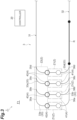
- FIG. 4 is a schematic plan view illustrating an example of the departure control when the transport vehicle 10 is not present in the first section Z1 of the first branch track 33d in the transport system 1.
- the transport vehicle 10 scheduled to enter the first section Z1 is not present either.
- the transport vehicle 10 having already unloaded to the unloading port 41 is not stopped.
- the transport vehicle 10 as an empty transport cart capable of transporting is not prepared.
- the controller 20 will prohibit the departure of the transport vehicle 10X in the current cycle.
- the transport vehicle 10X in the next cycle, whether its departure is prohibited is determined again. For example, if, in the next cycle, the transport vehicle 10 having already unloaded to the unloading port 41 is stopped behind the transport vehicle 10X, the transport vehicle 10X obtains release from the prohibition of departure and is caused to depart successively in sync with the transport vehicles 10 stopped at the stop positions of the first branch tracks 33a to 33c.
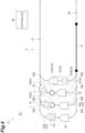
- FIG. 5 is a schematic plan view illustrating an example of the departure control when the transport vehicle 10 is present in the second section Z2 in the transport system 1.
- the departure control in the kth cycle causes the transport vehicles 10a stopped at the respective stop positions of the first branch tracks 33a to 33d to successively depart.
- a transport vehicle 10b at the rearmost of a group of transport vehicles having been caused to depart by the departure control in the (k-1)th cycle is still present in the second section Z2.
- the controller 20 will cancel the departure control in the kth cycle and prohibit the departure of all the stopped transport vehicles 10a.
- the certain section Z includes the first section Z1.
- the departure control prohibits the departure of the transport vehicle 10 stopped at the stop position of one of the branch tracks 33 when the transport vehicle 10 is not present in the first section Z1 of one of the branch tracks 33 and the transport vehicle 10 scheduled to enter the first section Z1 from the main track 32 is not present. With this, even when there is a shortage of the transport vehicles 10 in one of the branch tracks 33, the transport vehicle 10 can be stopped at the stop position for a sufficient amount of time, and the transport vehicle 10 can be surely loaded during that time.
- the departure control prohibits the departure of the transport vehicle 10 stopped at the stop position of one of the branch tracks 33 when the transport vehicle 10 having already unloaded to the unloading port 41 is not present in the first section Z1 of one of the branch tracks 33.
- the departure of the stopped transport vehicle 10 is prohibited, and it is possible to surely prevent the stopped transport vehicle 10 from forcedly departing without being able to be loaded.
- the certain section Z includes the second section Z2.
- the departure control prohibits the departure of all the transport vehicles 10 stopped at the respective stop positions of the first branch tracks 33a to 33d when the other transport vehicle 10b other than the transport vehicles 10 is present in the second section Z2. In this case, in the second section Z2 and areas around it, congestion due to a concentration of the transport vehicles 10 can be prevented from occurring.
- the departure control causes the transport vehicles 10 stopped at the respective stop positions of the first branch tracks 33a to 33d to depart at a timing repeated at a fixed cycle for each of the first branch tracks 33a to 33d and, for the transport vehicle 10 the departure in a certain cycle of which has been prohibited, determines again whether departure in the next cycle is prohibited.
- the above effect that is, causing each transport vehicle 10 to depart in accordance with an excess or shortage of the transport vehicles 10 can be specifically achieved while improving the efficiency in transporting the load L by causing each stopped transport vehicle 10 to depart at a timing at a fixed cycle.
- fluctuations in the pace of transport can be reduced.
- the departure control for the transport vehicle 10 the departure of which has been prohibited over certain cycles, permits departure in the next cycle. In this case, it is possible to avoid the transport vehicle 10 the departure of which has been prohibited in the departure control from not transporting the load L for a long period of time.
- the track 3 includes four first branch tracks 33a to 33d, but the number of the first branch tracks may be two, three, or five or more.
- the track 3 includes four second branch tracks 34a to 34d, but the number of the second branch tracks may be two, three, or five or more.
- the departure control causes the transport vehicle 10 to forcedly depart at a fixed cycle regardless of whether the load L is loaded but may cause the transport vehicle 10 to depart on the condition that the load L is loaded.
- the transport destination determination control to determine the transport destination of the transport vehicle 10 traveling in the specific section R is executed, but the transport destination determination control is not necessarily required to be executed, and the delivery port 4 as the transport destination may be determined at any timing.
- the virtual coupling control to perform control for each group of transport vehicles including a plurality of transport vehicles 10 is performed, but the virtual coupling control is not necessarily required to be executed.
- a transport system including:
- the transport system according to Invention 5 in which the departure control, for the transport vehicle the departure of which has been prohibited over certain cycles, permits departure in the next cycle.
Landscapes
- Engineering & Computer Science (AREA)
- Mechanical Engineering (AREA)
- Automation & Control Theory (AREA)
- Aviation & Aerospace Engineering (AREA)
- Radar, Positioning & Navigation (AREA)
- Remote Sensing (AREA)
- Physics & Mathematics (AREA)
- General Physics & Mathematics (AREA)
- Control Of Position, Course, Altitude, Or Attitude Of Moving Bodies (AREA)
Abstract
Description
- One aspect of the present invention relates to a transport system.
- A transport system including a plurality of transport vehicles traveling along a track and a controller configured to control the traveling of the transport vehicles is known. As technology related to such a transport system, for example, Patent Literature 1 describes a system in which transport vehicles stopped at respective stop positions of a plurality of branch tracks of the track are caused to depart at a timing according to the count of a pitch timer for each of the branch tracks.
- Patent Literature 1:
Japanese Patent No. 6935846 - In the transport system described above, for some reason, there may arise an excess or shortage of the transport vehicles present in a certain section on the track. In this case, for example, due to a shortage of the transport vehicles, the time during which a transport vehicle can be stopped at a stop position corresponding to a loading port may be reduced on a particular branch track, and the transport vehicle may depart without being able to be loaded. In addition, for example, due to a concentration of the transport vehicles, the departure of a transport vehicle may be blocked by a preceding transport vehicle, resulting in congestion. Consequently, it becomes difficult to smoothly transport loads by the transport vehicles.
- One aspect of the present invention has been made in view of the above circumstances, and an object thereof is to provide a transport system in which transport vehicles can smoothly transport loads.
- A transport system according to one aspect of the present invention is a transport system including a plurality of transport vehicles configured to travel along a track and transport a load and a controller configured to control traveling of the transport vehicles, the track having a first main track and a plurality of branch tracks connecting to the first main track via confluence points different from each other, the controller executing departure control that causes the transport vehicles stopped at respective stop positions of the branch tracks to depart toward the first main track for each of the branch tracks, and the departure control prohibiting, in accordance with whether the transport vehicle is present in a certain section on the track, departure of at least one of the transport vehicles stopped at the respective stop positions of the branch tracks.
- In this transport system, the transport vehicles stopped at the stop positions of the branch tracks depart for each branch track, and the departure of at least one of them is prohibited in accordance with an excess or shortage of the transport vehicles in the certain section on the track. This prevents transport from being congested due to a shortage and concentration of the transport vehicles and enables the transport vehicles to smoothly transport the load.
- In the transport system according to one aspect of the present invention, the track may have a second main track, the stop positions may correspond to loading ports for loading the transport vehicles, the second main track may branch off to the branch tracks via branch points different from each other, the certain section may include a first section, which is a section upstream of the stop position in each of the branch tracks, and the departure control may prohibit departure of the transport vehicle stopped at the stop position of one of the branch tracks when the transport vehicle is not present in the first section of one of the branch tracks and the transport vehicle scheduled to enter the first section from the second main track is not present. With this, even when there is a shortage of the transport vehicles in one of the branch tracks, the transport vehicle can be stopped at the stop position for a sufficient amount of time, and the transport vehicle can be surely loaded during that time. That is, it is possible to prevent the transport vehicle from departing without being able to be loaded in one of the branch tracks.
- In the transport system according to one aspect of the present invention, in the first section, an unloading port for unloading the load from the transport vehicle may be disposed along the track, and the departure control may prohibit departure of the transport vehicle stopped at the stop position of one of the branch tracks when the transport vehicle having already unloaded to the unloading port is not present in the first section of one of the branch tracks. In this case, it is possible to surely prevent the transport vehicle from departing without being able to be loaded in one of the branch tracks.
- In the transport system according to one aspect of the present invention, the certain section may include a second section, which is a section to the confluence point most downstream from the stop positions of the branch tracks in the track, and the departure control may prohibit departure of all the transport vehicles stopped at the respective stop positions of the branch tracks when another transport vehicle other than the transport vehicles is present in the second section. In this case, in the second section, congestion due to a concentration of the transport vehicles can be prevented from occurring.
- In the transport system according to one aspect of the present invention, the departure control may cause the transport vehicles stopped at the respective stop positions of the branch tracks to depart at a timing repeated at a fixed cycle for each of the branch tracks and, for the transport vehicle the departure in a certain cycle of which has been prohibited, may determine again whether departure in the next cycle is prohibited. In this case, the above effect, that is, causing each transport vehicle to depart in accordance with an excess or shortage of the transport vehicles can be specifically achieved while improving the efficiency in transporting the load by causing each stopped transport vehicle to depart at a timing at a fixed cycle.
- In the transport system according to one aspect of the present invention, the departure control, for the transport vehicle the departure of which has been prohibited over certain cycles, may permit departure in the next cycle. In this case, it is possible to avoid the transport vehicle the departure of which has been prohibited in the departure control from not transporting the load for a long period of time.
- One aspect of the present invention can provide a transport system capable of improving the efficiency in transporting the load.
-
- [
FIG. 1] FIG. 1 is a schematic plan view illustrating a transport system according to an embodiment. - [
FIG. 2] FIG. 2 is a side view illustrating a transport vehicle of the transport system inFIG. 1 . - [
FIG. 3] FIG. 3 is a schematic plan view illustrating a first building side of the transport system inFIG. 1 . - [
FIG. 4] FIG. 4 is a schematic plan view illustrating an example of departure control when the transport vehicle is not present in a first section in the transport system inFIG. 1 . - [
FIG. 5] FIG. 5 is a schematic plan view illustrating an example of the departure control when the transport vehicle is present in a second section in the transport system inFIG. 1 . - One embodiment will now be described with reference to the attached drawings. In description of the drawings, like or equivalent elements are designated by like reference signs, and duplicate description is omitted. The dimensional proportions in the drawings do not necessarily match those in the description.
- As illustrated in
FIG. 1 , this transport system 1 is a system configured to perform transport between two points in which a transport source and a transport destination are patterned. The transport system 1 performs inter-building transport, which performs delivery of loads between a first building F1 and a second building F2. The transport system 1 includes a plurality oftransport vehicles 10 and acontroller 20. Thetransport vehicles 10 travel along atrack 3 to transport loads. Thetransport vehicles 10 are configured to be capable of transferring loads. Thetransport vehicles 10 are Overhead Hoist Transports. Thetransport vehicles 10 are also referred to as, for example, vehicles (transport vehicles), overhead traveling vehicles (overhead transport vehicles), or traveling vehicles (traveling carts). The number of thetransport vehicles 10 included in the transport system 1 is, for example, about 50 and varies depending on the amount of transport demand and a transport distance. - As illustrated in
FIG. 2 , thetransport vehicle 10 includes atraveling cart 144, apower supply cart 145 configured to receive power supply from thetrack 3, aθ drive 147, and a laterallyfeeding unit 146 for laterally feeding the lower portion thereof with respect to thetrack 3. Theθ drive 147 turns a lifting and loweringdrive unit 148 in a horizontal plane to control the attitude of a load L. The lifting and loweringdrive unit 148 lifts and lowers a lifting and loweringplatform 149, which grasps the load L, and delivers the load L to and from adelivery port 4. The lifting and loweringplatform 149 grasps the portion of a flange 124 as the upper part of the load L. The laterallyfeeding unit 146 and theθ drive 147 are not necessarily required to be provided. The load L is, for example, a container storing a plurality of semiconductor wafers, but it may also be a glass substrate, a general component, or the like. - The
track 3 is laid on, for example, the ceiling or the like. Thetrack 3 is supported bycolumns 141. Thetrack 3 is a traveling path set in advance for causing thetransport vehicles 10 to travel. Thetrack 3 is a one-way traveling path. In other words, in the transport system 1, a traveling direction (a forward direction) of thetransport vehicles 10 on thetrack 3 is set to one direction, and traveling in the opposite direction is prohibited. Thetrack 3 has a closed track layout that is not affected from outside thetrack 3. In the following, the terms "upstream" and "downstream" correspond to "upstream" and "downstream," respectively, in the traveling direction of thetransport vehicles 10. - In the example illustrated in
FIG. 1 , thetrack 3 includesmain tracks first branch tracks main track 32 and joining themain track 31, and foursecond branch tracks main track 31 and joining themain track 32. Themain tracks main tracks main tracks main track transport vehicles 10 to travel in a circling manner. - The
first branch tracks 33a to 33d are disposed inside the first building F1. The first branch tracks 33a to 33d extend in parallel to each other. The first branch tracks 33a to 33d are provided in a comb-like manner between themain tracks main tracks - The following specifically describes the configuration and control of the transport system 1. In the following description, the configuration and control of the first building F1 will be described, and descriptions of the configuration and control of the second building F2 will be omitted as appropriate because they are similar.
- As illustrated in
FIG. 3 , points at which the first branch tracks 33a to 33d join themain track 31 areconfluence points main track 31 via each of the confluence points 35a, 35b, 35c, and 35d. That is, thetrack 3 has the confluence points 35a to 35d, which are a plurality of confluence points disposed spaced apart from each other on themain track 31. Themain track 31 is joined from each of the first branch tracks 33a to 33d via the confluence points 35a, 35b, 35c, and 35d different from each other. For example, it is regarded that the portion of thetrack 3 downstream of theconfluence point 35a is themain track 31, which is joined from thefirst branch track 33a upstream thereof. The first branch tracks 33a to 33d each connect to themain track 31 via the confluence points 35a to 35d different from each other. The confluence points 35a to 35d are separated from each other by a certain distance on themain track 31. - Points at which the first branch tracks 33a to 33d branch off from the
main track 32 arebranch points main track 32 via each of thebranch points track 3 has the branch points 36a to 36d, which are a plurality of branch points disposed spaced apart from each other on themain track 32. Themain track 32 branches off to each of the first branch tracks 33a to 33d via thebranch points track 3 upstream of thebranch point 36a is themain track 32, which branches off to thefirst branch track 33a downstream thereof. The first branch tracks 33a to 33d each connect to themain track 32 via the branch points 36a to 36d different from each other. The branch points 36a to 36d are separated from each other by a certain distance on themain track 32. - The "confluence point" is a point at which a branch track connects to a main track. The "confluence point" is a point at which the branch track leads to the main track. The "confluence point" is a connecting point of the branch track and the main track for allowing entry to the main track from the branch track. The "branch point" is a point at which the main track connects to the branch track. The "branch point" is a point at which the main track leads to the branch track. The "branch point" is a connecting point of the main track and the branch track for allowing entry to the branch track from the main track. In the example illustrated in
FIG. 3 , themain track 31 corresponds to a first main track, themain track 32 corresponds to a second main track, and the first branch tracks 33a to 33d correspond to branch tracks. - Each of the first branch tracks 33a to 33d has a stop position corresponding to the
delivery port 4 for thetransport vehicle 10 to deliver the load L. Thedelivery port 4 is disposed along each of the first branch tracks 33a to 33d. Thedelivery port 4 is provided, for example, on a conveyor (not illustrated) transporting the load L. Thedelivery port 4 has an unloadingport 41 and aloading port 42. - The unloading
port 41 is a port for unloading the load L from thetransport vehicle 10. At the unloadingport 41, after the load L is placed, the load L is removed before thesubsequent transport vehicle 10 arrives. The unloadingport 41 is disposed upstream of theloading port 42 with a certain gap. In other words, theloading port 42 is disposed downstream of the unloadingport 41 with a certain gap. Theloading port 42 is a port for loading the load L onto thetransport vehicle 10. Theloading port 42 can bring in the load L into the port in a span of consecutive arrivals of thetransport vehicles 10. As the unloadingport 41 and theloading port 42, there are no particular limitations, and various known ports can be employed. - As illustrated in
FIG. 3 , thecontroller 20 is an electronic control unit constituted by a central processing unit (CPU), a read only memory (ROM), a random access memory (RAM), and the like. Thecontroller 20 can be configured as software in which, for example, a program stored in the ROM is loaded onto the RAM and is executed by the CPU. Thecontroller 20 may be configured as hardware including electronic circuitry or the like. Thecontroller 20 communicates with thetransport vehicles 10 and controls the traveling of thetransport vehicles 10. - The
controller 20 executes departure control that causes thetransport vehicles 10 stopped at stop positions corresponding to therespective delivery ports 4 of the first branch tracks 33a to 33d (in this case, stop positions corresponding to the loading ports 42) to depart toward themain track 31 for each of the first branch tracks 33a to 33d. In the following, the stop position corresponding to theloading port 42 may also be referred to simply as the "stop position". The upstream and downstream of the departure control correspond to the upstream and downstream of themain track 31, and the upstream and downstream of the entry control correspond to the upstream and downstream of themain track 32. - The departure control causes the
transport vehicle 10 stopped on the downstream first branch track among the first branch tracks 33a to 33d to depart at the same time as or earlier than thetransport vehicle 10 stopped on the upstream first branch track. Specifically, the departure control causes thetransport vehicle 10 stopped on thefirst branch track 33d to depart at the same time as or earlier than thetransport vehicle 10 stopped on thefirst branch track 33c. The departure control causes thetransport vehicle 10 stopped on thefirst branch track 33c to depart at the same time as or earlier than thetransport vehicle 10 stopped on thefirst branch track 33b. The departure control causes thetransport vehicle 10 stopped on thefirst branch track 33b to depart at the same time as or earlier than thetransport vehicle 10 stopped on thefirst branch track 33a. - More specifically, the departure control causes each of the stopped
transport vehicles 10 to depart (forcedly depart) regardless of whether the load L is loaded at a timing repeated at a fixed cycle for each of the first branch tracks 33a to 33d. For example, the departure control starts counting down from a standard pitch time by a pitch timer in each of the first branch tracks 33a to 33d. When the count of the pitch timer reaches 0, thetransport vehicle 10 stopped at the stop position is caused to depart, and the count of the pitch timer is reset to the standard pitch time. The counting down is then continued by the pitch timer. The standard pitch time may be a fixed value set in advance or a variable value. In the present embodiment, the time axes of the pitch timers for the respective first branch tracks 33a to 33d are shifted so that thetransport vehicle 10 stopped on the downstream first branch track departs first. - The
controller 20 executes the entry control configured to cause each of thetransport vehicles 10 traveling on themain track 32 to successively enter each of the first branch tracks 33a to 33d in the order from downstream to upstream. Specifically, in the entry control, thetransport vehicle 10 is caused to enter thefirst branch track 33a, thenext transport vehicle 10 is caused to enter thefirst branch track 33b, thenext transport vehicle 10 is caused to enter thefirst branch track 33c, thenext transport vehicle 10 is caused to enter thefirst branch track 33d, and then such entry of thetransport vehicle 10 is repeated. - In the entry control, transport destination determination control to determine (guide) a transport destination is performed for the
transport vehicle 10 traveling through a specific section R upstream of the branch points 36a to 36d in themain track 32. The specific section R is a straight section close to the branch points 36a to 36d. The specific section R is not limited to a particular section so long as it is upstream of the branch points 36a to 36d. The specific section R is not limited to a straight section, but may be a section including a curve, and may be various sections. The transport destination determination control determines thedelivery port 4 as the transport determination (in this case, the unloadingport 41 of any of the first branch tracks 33a to 33d) . - The
controller 20 grasps the number (the entry number) of thetransport vehicles 10 present on each of the first branch tracks 33a to 33d. Specifically, in the entry control, at a timing when the transport destination is determined by the transport destination determination control described above, thecontroller 20 increases (counts up) the number of thetransport vehicles 10 present on any of the first branch tracks 33a to 33d corresponding to the transport destination by one. When causing thetransport vehicle 10 stopped at the stop position of any of the first branch tracks 33a to 33d to depart in the departure control, thecontroller 20 reduces (counts down) the number of thetransport vehicles 10 present on any of the first branch tracks 33a to 33d by one at a timing of the departure. - Referring back to
FIG. 1 , thecontroller 20 executes virtual coupling control to perform the departure control and the entry control described above for each group of transport vehicles including a plurality of (four in this case)transport vehicles 10 corresponding to the number of the first branch tracks 33a to 33d. Thecontroller 20 causes thetransport vehicles 10 to travel along the circling tracks (themain tracks controller 20 causes thetransport vehicle 10 having been caused to enter thefirst branch track 33d to enter thesecond branch track 34a, causes thetransport vehicle 10 having been caused to enter thefirst branch track 33c to enter thesecond branch track 34b, causes thetransport vehicle 10 having been caused to enter thefirst branch track 33b to enter thesecond branch track 34c, and causes thetransport vehicle 10 having been caused to enter thefirst branch track 33a to enter thesecond branch track 34d. In the entry control, thecontroller 20 causes thetransport vehicle 10 having been caused to enter thesecond branch track 34d to enter thefirst branch track 33a, causes thetransport vehicle 10 having been caused to enter thesecond branch track 34c to enter thefirst branch track 33b, causes thetransport vehicle 10 having been caused to enter thesecond branch track 34b to enter thefirst branch track 33c, and causes thetransport vehicle 10 having been caused to enter thesecond branch track 34a to enter thefirst branch track 33d. - The departure control of the present embodiment prohibits, in accordance with whether the
transport vehicle 10 is present in a certain section Z on thetrack 3, the departure of at least one of thetransport vehicles 10 stopped at the stop positions corresponding to therespective loading ports 42 of the first branch tracks 33a to 33d. For example, the presence of thetransport vehicle 10 in the certain section Z includes the presence of a standard position as a standard of the position of the transport vehicle 10 (such as the central position of the transport vehicle 10) within the certain section Z. For example, the presence of thetransport vehicle 10 in the certain section Z includes thetransport vehicle 10 being actually present and being scheduled to be present. - As illustrated in
FIG. 3 , the certain section Z includes a first section Z1 and a second section Z2. The first section Z1 is a section upstream of the stop position corresponding to theloading port 42 in each of the first branch tracks 33a to 33d. In the first section Z1, the unloadingport 41 is disposed along each of the first branch tracks 33a to 33d. In other words, the first section Z1 includes at least the stop position corresponding to the unloadingport 41. The first section Z1 is provided such that thetransport vehicle 10 present therein does not physically interfere with thetransport vehicle 10 stopped at the stop position corresponding to theloading port 42. - The second section Z2 is a section from the stop positions corresponding to the
loading ports 42 of the first branch tracks 33a to 33d to the mostdownstream confluence point 35d in thetrack 3. The second section Z2 includes a section downstream of the stop positions corresponding to theloading ports 42 in the respective first branch tracks 33a to 33d and a section from theconfluence point 35a to theconfluence point 35d in themain track 31. The second section Z2 is also referred to as a gate-closed section. The second section Z2 is provided such that thetransport vehicle 10 present therein does not physically interfere with thetransport vehicle 10 stopped at the stop position corresponding to theloading port 42. - The departure control prohibits the departure of the
transport vehicle 10 stopped at the stop position corresponding to theloading port 42 of one of the branch tracks 33 when thetransport vehicle 10 is not present in the first section Z1 of one of the branch tracks 33 and thetransport vehicle 10 scheduled to enter the first section Z1 of one of the branch tracks 33 from themain track 32 is not present. One of the branch tracks 33 means any of the first branch tracks 33a to 33d. Thetransport vehicle 10 scheduled to enter the first section Z1 of one of the branch tracks 33 from themain track 32 is, for example, thetransport vehicle 10 traveling through the specific section R, thetransport vehicle 10 for which the unloadingport 41 along one of the branch tracks 33 having been determined as the transport destination by the transport destination determination control. - For example, the departure control prohibits the departure of the
transport vehicle 10 stopped at the stop position of one of the branch tracks 33 when thetransport vehicle 10 having already unloaded to the unloadingport 41 is not present (not stopped) at the stop position corresponding to the unloadingport 41 in the first section Z1 of one of the branch tracks 33. - The departure control prohibits the departure of all the
transport vehicles 10 stopped at the stop positions corresponding to therespective loading ports 42 of the first branch tracks 33a to 33d (in other words, a group of transport vehicles to be caused to depart in the departure control in the same cycle) when anothertransport vehicle 10 other than thetransport vehicles 10 is present in the second section Z2. Theother transport vehicle 10 may be, for example, thetransport vehicle 10 included in a group of transport vehicles having been caused to depart in the departure control in the previous cycle. Whether theother transport vehicle 10 is present in the second section Z2 can be determined by thecontroller 20, for example, based on the position information of thetransport vehicles 10 obtained by periodically performing communication with thetransport vehicles 10. - As described above, the departure control causes the
transport vehicles 10 stopped at the stop positions corresponding to therespective loading ports 42 of the first branch tracks 33a to 33d to depart at a timing repeated at a fixed cycle for each of the first branch tracks 33a to 33d. The departure control, for the transport vehicle the departure in a certain cycle of which has been prohibited, determines again whether departure in the next cycle is prohibited. The departure control, for thetransport vehicle 10 the departure of which has been prohibited over certain cycles, unconditionally permits departure in the next cycle. The certain cycles correspond to n cycles of the pitch timer (n is a set constant, and n = 3, for example). -
FIG. 4 is a schematic plan view illustrating an example of the departure control when thetransport vehicle 10 is not present in the first section Z1 of thefirst branch track 33d in the transport system 1. In the example inFIG. 4 , thetransport vehicle 10 scheduled to enter the first section Z1 is not present either. As illustrated inFIG. 4 , in the first section Z1 of thefirst branch track 33d, thetransport vehicle 10 having already unloaded to the unloadingport 41 is not stopped. In other words, on thefirst branch track 33d, behind atransport vehicle 10X, which is stopped at the stop position corresponding to theloading port 42, thetransport vehicle 10 as an empty transport cart capable of transporting is not prepared. Thus, in this case, thecontroller 20 will prohibit the departure of thetransport vehicle 10X in the current cycle. - For the
transport vehicle 10X, in the next cycle, whether its departure is prohibited is determined again. For example, if, in the next cycle, thetransport vehicle 10 having already unloaded to the unloadingport 41 is stopped behind thetransport vehicle 10X, thetransport vehicle 10X obtains release from the prohibition of departure and is caused to depart successively in sync with thetransport vehicles 10 stopped at the stop positions of the first branch tracks 33a to 33c. -
FIG. 5 is a schematic plan view illustrating an example of the departure control when thetransport vehicle 10 is present in the second section Z2 in the transport system 1. In the example inFIG. 5 , the departure control in the kth cycle causes thetransport vehicles 10a stopped at the respective stop positions of the first branch tracks 33a to 33d to successively depart. In this process, atransport vehicle 10b at the rearmost of a group of transport vehicles having been caused to depart by the departure control in the (k-1)th cycle is still present in the second section Z2. Thus, in this case, thecontroller 20 will cancel the departure control in the kth cycle and prohibit the departure of all the stoppedtransport vehicles 10a. - As described above, in the transport system 1, the
transport vehicles 10 stopped at the stop positions of the first branch tracks 33a to 33d depart for each of the first branch tracks 33a to 33d. Along with this, the departure of at least one of them is prohibited in accordance with an excess or shortage of thetransport vehicles 10 in the certain section Z on thetrack 3. This prevents transport from being congested due to a shortage and concentration of thetransport vehicles 10 and enables thetransport vehicles 10 to smoothly transport the load L. - In the transport system 1, the certain section Z includes the first section Z1. The departure control prohibits the departure of the
transport vehicle 10 stopped at the stop position of one of the branch tracks 33 when thetransport vehicle 10 is not present in the first section Z1 of one of the branch tracks 33 and thetransport vehicle 10 scheduled to enter the first section Z1 from themain track 32 is not present. With this, even when there is a shortage of thetransport vehicles 10 in one of the branch tracks 33, thetransport vehicle 10 can be stopped at the stop position for a sufficient amount of time, and thetransport vehicle 10 can be surely loaded during that time. - Consequently, it is possible to prevent the
transport vehicle 10 from departing (forcedly departing) without being able to be loaded on one of the branch tracks 33. In addition, even if there arises a bias between the number of thetransport vehicles 10 traveling in a direction from the first building F1 toward the second building F2 and the number of thetransport vehicles 10 traveling in a direction from the second building F2 toward the first building F1, the bias can be automatically eliminated to be balanced. Even if one of the branch tracks 33 with a shortage of thetransport vehicles 10 occurs, it is possible to accumulate thetransport vehicles 10 on one of the branch tracks 33, eliminating the shortage of thetransport vehicles 10 on one of the branch tracks 33. - In the transport system 1, the departure control prohibits the departure of the
transport vehicle 10 stopped at the stop position of one of the branch tracks 33 when thetransport vehicle 10 having already unloaded to the unloadingport 41 is not present in the first section Z1 of one of the branch tracks 33. In this case, for example, when anothertransport vehicle 10 as an empty cart is not present immediately behind thetransport vehicle 10 stopped on one of the branch tracks 33, the departure of the stoppedtransport vehicle 10 is prohibited, and it is possible to surely prevent the stoppedtransport vehicle 10 from forcedly departing without being able to be loaded. - In the transport system 1, the certain section Z includes the second section Z2. The departure control prohibits the departure of all the
transport vehicles 10 stopped at the respective stop positions of the first branch tracks 33a to 33d when theother transport vehicle 10b other than thetransport vehicles 10 is present in the second section Z2. In this case, in the second section Z2 and areas around it, congestion due to a concentration of thetransport vehicles 10 can be prevented from occurring. - In the transport system 1, the departure control causes the
transport vehicles 10 stopped at the respective stop positions of the first branch tracks 33a to 33d to depart at a timing repeated at a fixed cycle for each of the first branch tracks 33a to 33d and, for thetransport vehicle 10 the departure in a certain cycle of which has been prohibited, determines again whether departure in the next cycle is prohibited. In this case, the above effect, that is, causing eachtransport vehicle 10 to depart in accordance with an excess or shortage of thetransport vehicles 10 can be specifically achieved while improving the efficiency in transporting the load L by causing each stoppedtransport vehicle 10 to depart at a timing at a fixed cycle. In addition, fluctuations in the pace of transport can be reduced. - In the transport system 1, the departure control, for the
transport vehicle 10 the departure of which has been prohibited over certain cycles, permits departure in the next cycle. In this case, it is possible to avoid thetransport vehicle 10 the departure of which has been prohibited in the departure control from not transporting the load L for a long period of time. - Although one embodiment according to the present invention has been described above, the present invention is not limited to the above-described embodiment, and various modifications can be made within the scope not departing from the gist of the invention.
- In the above embodiment, the
track 3 includes four first branch tracks 33a to 33d, but the number of the first branch tracks may be two, three, or five or more. Similarly, thetrack 3 includes four second branch tracks 34a to 34d, but the number of the second branch tracks may be two, three, or five or more. - In the above embodiment, the departure control causes the
transport vehicle 10 to forcedly depart at a fixed cycle regardless of whether the load L is loaded but may cause thetransport vehicle 10 to depart on the condition that the load L is loaded. In the above embodiment, the transport destination determination control to determine the transport destination of thetransport vehicle 10 traveling in the specific section R is executed, but the transport destination determination control is not necessarily required to be executed, and thedelivery port 4 as the transport destination may be determined at any timing. In the above embodiment, the virtual coupling control to perform control for each group of transport vehicles including a plurality oftransport vehicles 10 is performed, but the virtual coupling control is not necessarily required to be executed. - The following describes the requirements of one aspect of the present invention.
- A transport system including:
- a plurality of transport vehicles configured to travel along a track and transport a load; and
- a controller configured to control traveling of the transport vehicles,
- the track having a first main track and a plurality of branch tracks connecting to the first main track via confluence points different from each other,
- the controller executing departure control that causes the transport vehicles stopped at respective stop positions of the branch tracks to depart toward the first main track for each of the branch tracks,
- the departure control prohibiting, in accordance with whether the transport vehicle is present in a certain section on the track, departure of at least one of the transport vehicles stopped at the respective stop positions of the branch tracks.
- The transport system according to Invention 1, in which
- the track has a second main track,
- the stop positions correspond to loading ports for loading the transport vehicles,
- the branch tracks connect to the second main track via branch points different from each other,
- the certain section includes a first section, which is a section upstream of the stop position in each of the branch tracks, and
- the departure control prohibits departure of the transport vehicle stopped at the stop position of one of the branch tracks when the transport vehicle is not present in the first section of one of the branch tracks and the transport vehicle scheduled to enter the first section from the second main track is not present.
- The transport system according to Invention 2, in which
- in the first section, an unloading port for unloading the load from the transport vehicle is disposed along the track, and
- the departure control prohibits departure of the transport vehicle stopped at the stop position of one of the branch tracks when the transport vehicle having already unloaded to the unloading port is not present in the first section of one of the branch tracks.
- The transport system according to any one of Inventions 1 to 3, in which
- the certain section includes a second section, which is a section to the confluence point most downstream from the stop positions of the branch tracks in the track, and
- the departure control prohibits departure of all the transport vehicles stopped at the respective stop positions of the branch tracks when another transport vehicle other than the transport vehicles is present in the second section.
- The transport system according to any one of Inventions 1 to 4, in which the departure control
- causes the transport vehicles stopped at the respective stop positions of the branch tracks to depart at a timing repeated at a fixed cycle for each of the branch tracks and,
- for the transport vehicle the departure in a certain cycle of which has been prohibited, determines again whether departure in the next cycle is prohibited.
- The transport system according to Invention 5, in which the departure control, for the transport vehicle the departure of which has been prohibited over certain cycles, permits departure in the next cycle.
-
- 1 ... transport system
- 3 ... track
- 4 ... delivery port
- 10, 10a, 10b, 10X ... transport vehicle
- 20 ... controller
- 31 ... main track (first main track)
- 32 ... main track (second main track)
- 33a to 33d ... first branch track (branch track)
- 34a to 34d ... second branch track
- 35a to 35d ... confluence point
- 36a to 36d ... branch point
- 41 ... unloading port
- 42 ... loading port
- L ... load
- R ... specific section
- Z ... certain section
- Z1 ... first section
- Z2 ... second section
Claims (6)
- A transport system comprising:a plurality of transport vehicles configured to travel along a track and transport a load; anda controller configured to control traveling of the transport vehicles,the track having a first main track and a plurality of branch tracks connecting to the first main track via confluence points different from each other,the controller executing departure control that causes the transport vehicles stopped at respective stop positions of the branch tracks to depart toward the first main track for each of the branch tracks,the departure control prohibiting, in accordance with whether the transport vehicle is present in a certain section on the track, departure of at least one of the transport vehicles stopped at the respective stop positions of the branch tracks.
- The transport system according to claim 1, whereinthe track has a second main track,the stop positions correspond to loading ports for loading the transport vehicles,the second main track branches off to the branch tracks via branch points different from each other,the certain section includes a first section, which is a section upstream of the stop position in each of the branch tracks, andthe departure control prohibits departure of the transport vehicle stopped at the stop position of one of the branch tracks when the transport vehicle is not present in the first section of one of the branch tracks and the transport vehicle scheduled to enter the first section from the second main track is not present.
- The transport system according to claim 2, whereinin the first section, an unloading port for unloading the load from the transport vehicle is disposed along the track, andthe departure control prohibits departure of the transport vehicle stopped at the stop position of one of the branch tracks when the transport vehicle having already unloaded to the unloading port is not present in the first section of one of the branch tracks.
- The transport system according to any one of claims 1 to 3, in whichthe certain section includes a second section, which is a section to the confluence point most downstream from the stop positions of the branch tracks in the track, andthe departure control prohibits departure of all the transport vehicles stopped at the respective stop positions of the branch tracks when another transport vehicle other than the transport vehicles is present in the second section.
- The transport system according to any one of claims 1 to 3, wherein the departure controlcauses the transport vehicles stopped at the respective stop positions of the branch tracks to depart at a timing repeated at a fixed cycle for each of the branch tracks and,for the transport vehicle the departure in a certain cycle of which has been prohibited, determines again whether departure in the next cycle is prohibited.
- The transport system according to claim 5, wherein the departure control, for the transport vehicle the departure of which has been prohibited over certain cycles, permits departure in the next cycle.
Applications Claiming Priority (2)
| Application Number | Priority Date | Filing Date | Title |
|---|---|---|---|
| JP2022091671 | 2022-06-06 | ||
| PCT/JP2023/013322 WO2023238484A1 (en) | 2022-06-06 | 2023-03-30 | Conveyance system |
Publications (2)
| Publication Number | Publication Date |
|---|---|
| EP4492179A1 true EP4492179A1 (en) | 2025-01-15 |
| EP4492179A4 EP4492179A4 (en) | 2026-05-20 |
Family
ID=89118063
Family Applications (1)
| Application Number | Title | Priority Date | Filing Date |
|---|---|---|---|
| EP23819471.6A Pending EP4492179A4 (en) | 2022-06-06 | 2023-03-30 | CONVEYOR SYSTEM |
Country Status (7)
| Country | Link |
|---|---|
| US (1) | US20250229994A1 (en) |
| EP (1) | EP4492179A4 (en) |
| JP (1) | JP7790565B2 (en) |
| KR (1) | KR102888948B1 (en) |
| CN (1) | CN118679439A (en) |
| TW (1) | TW202348471A (en) |
| WO (1) | WO2023238484A1 (en) |
Family Cites Families (3)
| Publication number | Priority date | Publication date | Assignee | Title |
|---|---|---|---|---|
| JP6652084B2 (en) * | 2017-02-09 | 2020-02-19 | 株式会社ダイフク | Goods transport equipment |
| JP6935846B2 (en) | 2018-05-01 | 2021-09-15 | 村田機械株式会社 | Transport system |
| JP2022125369A (en) * | 2019-07-04 | 2022-08-29 | 村田機械株式会社 | Traveling system |
-
2023
- 2023-03-30 CN CN202380020678.3A patent/CN118679439A/en active Pending
- 2023-03-30 KR KR1020247040157A patent/KR102888948B1/en active Active
- 2023-03-30 US US18/850,702 patent/US20250229994A1/en active Pending
- 2023-03-30 WO PCT/JP2023/013322 patent/WO2023238484A1/en not_active Ceased
- 2023-03-30 JP JP2024526250A patent/JP7790565B2/en active Active
- 2023-03-30 EP EP23819471.6A patent/EP4492179A4/en active Pending
- 2023-04-12 TW TW112113605A patent/TW202348471A/en unknown
Also Published As
| Publication number | Publication date |
|---|---|
| KR20250004073A (en) | 2025-01-07 |
| JP7790565B2 (en) | 2025-12-23 |
| KR102888948B1 (en) | 2025-11-19 |
| JPWO2023238484A1 (en) | 2023-12-14 |
| TW202348471A (en) | 2023-12-16 |
| EP4492179A4 (en) | 2026-05-20 |
| US20250229994A1 (en) | 2025-07-17 |
| WO2023238484A1 (en) | 2023-12-14 |
| CN118679439A (en) | 2024-09-20 |
Similar Documents
| Publication | Publication Date | Title |
|---|---|---|
| KR102389724B1 (en) | conveying system | |
| EP3848769B1 (en) | Conveyance vehicle system | |
| CN102448854B (en) | Conveyor system | |
| TWI402643B (en) | Unmanned delivery device and method for determining delivery path thereof | |
| CN108885440A (en) | For controlling the method sorted to the conveying object on conveying equipment by the time | |
| JP7276595B2 (en) | AUTOMATED WAREHOUSE SYSTEM AND AUTOMATED WAREHOUSE SYSTEM CONTROL METHOD | |
| US20050056576A1 (en) | Method and apparatus for storing travel luggage | |
| CN108885441B (en) | Method for sorting conveyed objects, conveying technology elements or nodes and conveying equipment | |
| JP5850261B2 (en) | Sorting system and method for controlling loading of baggage in sorting system | |
| US20250229994A1 (en) | Conveyance system | |
| JP4747274B2 (en) | Automated guided vehicle equipment | |
| JP4084240B2 (en) | Operation method of stacker crane in automatic warehouse | |
| JP7379822B2 (en) | Pallet transport allocation information generation device, generation method, and generation program | |
| JP5374981B2 (en) | Transport system | |
| JP7841590B2 (en) | Conveying system | |
| JP2000330634A (en) | Transport system | |
| JPH02158810A (en) | Conveyance control method for truck | |
| JP2002332105A (en) | Automatic guided vehicle system | |
| JP7501474B2 (en) | Item storage facilities | |
| WO2024127511A1 (en) | Transport control system, transport control method, and program | |
| JP2004283994A (en) | Transfer control system | |
| JPH0940104A (en) | Transport control system | |
| JP2011121656A (en) | Guided vehicle system | |
| JPH09255104A (en) | Junction and branching device |
Legal Events
| Date | Code | Title | Description |
|---|---|---|---|
| STAA | Information on the status of an ep patent application or granted ep patent |
Free format text: STATUS: THE INTERNATIONAL PUBLICATION HAS BEEN MADE |
|
| PUAI | Public reference made under article 153(3) epc to a published international application that has entered the european phase |
Free format text: ORIGINAL CODE: 0009012 |
|
| STAA | Information on the status of an ep patent application or granted ep patent |
Free format text: STATUS: REQUEST FOR EXAMINATION WAS MADE |
|
| 17P | Request for examination filed |
Effective date: 20241008 |
|
| AK | Designated contracting states |
Kind code of ref document: A1 Designated state(s): AL AT BE BG CH CY CZ DE DK EE ES FI FR GB GR HR HU IE IS IT LI LT LU LV MC ME MK MT NL NO PL PT RO RS SE SI SK SM TR |
|
| DAV | Request for validation of the european patent (deleted) | ||
| DAX | Request for extension of the european patent (deleted) | ||
| REG | Reference to a national code |
Ref country code: DE Ref legal event code: R079 Free format text: PREVIOUS MAIN CLASS: G05D0001020000 Ipc: H10P0072000000 |