EP4492036A1 - Evaluation method, evaluation device, and program - Google Patents
Evaluation method, evaluation device, and program Download PDFInfo
- Publication number
- EP4492036A1 EP4492036A1 EP23766902.3A EP23766902A EP4492036A1 EP 4492036 A1 EP4492036 A1 EP 4492036A1 EP 23766902 A EP23766902 A EP 23766902A EP 4492036 A1 EP4492036 A1 EP 4492036A1
- Authority
- EP
- European Patent Office
- Prior art keywords
- evaluation target
- evaluation
- image
- defect part
- signal intensity
- Prior art date
- Legal status (The legal status is an assumption and is not a legal conclusion. Google has not performed a legal analysis and makes no representation as to the accuracy of the status listed.)
- Withdrawn
Links
Images




Classifications
-
- G—PHYSICS
- G01—MEASURING; TESTING
- G01N—INVESTIGATING OR ANALYSING MATERIALS BY DETERMINING THEIR CHEMICAL OR PHYSICAL PROPERTIES
- G01N3/00—Investigating strength properties of solid materials by application of mechanical stress
- G01N3/30—Investigating strength properties of solid materials by application of mechanical stress by applying a single impulsive force, e.g. by falling weight
- G01N3/303—Investigating strength properties of solid materials by application of mechanical stress by applying a single impulsive force, e.g. by falling weight generated only by free-falling weight
-
- G—PHYSICS
- G01—MEASURING; TESTING
- G01N—INVESTIGATING OR ANALYSING MATERIALS BY DETERMINING THEIR CHEMICAL OR PHYSICAL PROPERTIES
- G01N23/00—Investigating or analysing materials by the use of wave or particle radiation, e.g. X-rays or neutrons, not covered by groups G01N3/00 – G01N17/00, G01N21/00 or G01N22/00
- G01N23/20—Investigating or analysing materials by the use of wave or particle radiation, e.g. X-rays or neutrons, not covered by groups G01N3/00 – G01N17/00, G01N21/00 or G01N22/00 by using diffraction of the radiation by the materials, e.g. for investigating crystal structure; by using scattering of the radiation by the materials, e.g. for investigating non-crystalline materials; by using reflection of the radiation by the materials
- G01N23/201—Investigating or analysing materials by the use of wave or particle radiation, e.g. X-rays or neutrons, not covered by groups G01N3/00 – G01N17/00, G01N21/00 or G01N22/00 by using diffraction of the radiation by the materials, e.g. for investigating crystal structure; by using scattering of the radiation by the materials, e.g. for investigating non-crystalline materials; by using reflection of the radiation by the materials by measuring small-angle scattering
-
- G—PHYSICS
- G01—MEASURING; TESTING
- G01N—INVESTIGATING OR ANALYSING MATERIALS BY DETERMINING THEIR CHEMICAL OR PHYSICAL PROPERTIES
- G01N23/00—Investigating or analysing materials by the use of wave or particle radiation, e.g. X-rays or neutrons, not covered by groups G01N3/00 – G01N17/00, G01N21/00 or G01N22/00
- G01N23/02—Investigating or analysing materials by the use of wave or particle radiation, e.g. X-rays or neutrons, not covered by groups G01N3/00 – G01N17/00, G01N21/00 or G01N22/00 by transmitting the radiation through the material
- G01N23/04—Investigating or analysing materials by the use of wave or particle radiation, e.g. X-rays or neutrons, not covered by groups G01N3/00 – G01N17/00, G01N21/00 or G01N22/00 by transmitting the radiation through the material and forming images of the material
- G01N23/041—Phase-contrast imaging, e.g. using grating interferometers
-
- G—PHYSICS
- G01—MEASURING; TESTING
- G01N—INVESTIGATING OR ANALYSING MATERIALS BY DETERMINING THEIR CHEMICAL OR PHYSICAL PROPERTIES
- G01N3/00—Investigating strength properties of solid materials by application of mechanical stress
- G01N3/20—Investigating strength properties of solid materials by application of mechanical stress by applying steady bending forces
-
- G—PHYSICS
- G01—MEASURING; TESTING
- G01N—INVESTIGATING OR ANALYSING MATERIALS BY DETERMINING THEIR CHEMICAL OR PHYSICAL PROPERTIES
- G01N2203/00—Investigating strength properties of solid materials by application of mechanical stress
- G01N2203/02—Details not specific for a particular testing method
- G01N2203/06—Indicating or recording means; Sensing means
- G01N2203/0641—Indicating or recording means; Sensing means using optical, X-ray, ultraviolet, infrared or similar detectors
-
- G—PHYSICS
- G01—MEASURING; TESTING
- G01N—INVESTIGATING OR ANALYSING MATERIALS BY DETERMINING THEIR CHEMICAL OR PHYSICAL PROPERTIES
- G01N2223/00—Investigating materials by wave or particle radiation
- G01N2223/05—Investigating materials by wave or particle radiation by diffraction, scatter or reflection
- G01N2223/054—Investigating materials by wave or particle radiation by diffraction, scatter or reflection small angle scatter
-
- G—PHYSICS
- G01—MEASURING; TESTING
- G01N—INVESTIGATING OR ANALYSING MATERIALS BY DETERMINING THEIR CHEMICAL OR PHYSICAL PROPERTIES
- G01N2223/00—Investigating materials by wave or particle radiation
- G01N2223/30—Accessories, mechanical or electrical features
- G01N2223/303—Accessories, mechanical or electrical features calibrating, standardising
-
- G—PHYSICS
- G01—MEASURING; TESTING
- G01N—INVESTIGATING OR ANALYSING MATERIALS BY DETERMINING THEIR CHEMICAL OR PHYSICAL PROPERTIES
- G01N2223/00—Investigating materials by wave or particle radiation
- G01N2223/40—Imaging
- G01N2223/401—Imaging image processing
-
- G—PHYSICS
- G01—MEASURING; TESTING
- G01N—INVESTIGATING OR ANALYSING MATERIALS BY DETERMINING THEIR CHEMICAL OR PHYSICAL PROPERTIES
- G01N2223/00—Investigating materials by wave or particle radiation
- G01N2223/60—Specific applications or type of materials
- G01N2223/646—Specific applications or type of materials flaws, defects
Definitions
- the present invention relates to an evaluation method, an evaluation apparatus, and a program.
- Glass is a typical brittle material and has excellent transparency, chemical resistance, and heat resistance. Thus, glass is suitable for applications where defined chemical and physical properties are important. Examples of such applications include displays, various sensors, solar cells, and micromechanical parts.
- Ultra-thin glass has been developed as a cover glass and display for devices such as smart phones, tablets, watches and other wearable devices due to its flexibility.
- the UTG can also be used as a cover glass of a fingerprint sensor module and a lens cover of a camera.
- a glass sheet that is less than 0.5 mm thick like UTG tends to have defects that mainly result in breakage, such as cracks and chipping at the glass edge. Handling of such a glass sheet is tremendously difficult. Also, a thinner glass sheet results in a significant decrease of the overall mechanical strength (i.e., bending or impact strength).
- a pen drop test In a known pen drop test, a pen is dropped to hit a glass, and it is determined whether the glass is broken or not, based on qualitative evaluation by visual observation. According to the visual evaluation, it is possible to confirm that the glass is broken, but it is not possible to determine to what extent the glass is broken in the thickness direction. That is, in a case where the glass is used for a protective cover, it is not possible to determine whether the damage has reached the product to be protected.
- Patent Document 1 discloses a method for visualizing a two-dimensional size of a cracks and a void and distribution of cracks and voids generated inside a test piece made of resin and CFRP (Carbon Fiber Reinforced Plastics) by a tensile test, by using a small-angle scattering image and a differential phase image generated by X-ray Talbot imaging.
- CFRP Carbon Fiber Reinforced Plastics
- Patent literature 1 Japanese Unexamined Patent Publication No. 2020-187088
- Patent Document 1 can clarify the two-dimensional size and in-plane distribution of cracks and voids, these are all limited to two-dimensional information. That is, it is not possible to quantitatively learn depth-direction information of the crack (to what extent the sample is cracked in the thickness direction) only by generating the small-angle scattering image and the differential phase image and visualizing the entire crack generated in the sample, as disclosed in Patent Document 1.
- the differential phase image in which the signal intensity changes according to the refraction of the X-rays.
- a fiber-oriented resin such as CFRP
- CFRP fiber-oriented resin
- X-rays are refracted not only at the position of a generated crack but also at the fiber portion h of the evaluation target H, as shown in FIG. 10 . Therefore, it is not possible to extract the signal of the crack portion only and to calculate the depth of the crack, based on the signal intensity of the differential phase image.
- An object of the present invention is to provide an evaluation method, an evaluation apparatus, and a program that allow quantitative evaluation of the entire defect part in a brittle material having a high transmittance.
- an evaluation target is a brittle material having a high transmittance (I/Io) of an electromagnetic wave including light and having a defect part
- the method including: imaging the evaluation target to obtain a small-angle scattering image; obtaining a scattering signal intensity of the defect part from the small-angle scattering image; and calculating depth-direction information of the defect part from the scattering signal intensity.
- an evaluation method using a Talbot imaging apparatus wherein in the evaluation, an evaluation target is a brittle material having a high transmittance (I/Io) of an electromagnetic wave including light and having a defect part, the method including: imaging the evaluation target to obtain a small-angle scattering image; obtaining a scattering signal intensity of the defect part from the small-angle scattering image; and calculating depth-direction information of the defect part from the scattering signal intensity.
- I/Io transmittance
- an evaluation apparatus including: an irradiation device that emits an electromagnetic wave including light; gratings; a detector; a generation means; and a calculation means, wherein the irradiation device, the gratings, and the detector are arranged in an irradiation axis direction, wherein an evaluation target is a brittle material that has a high transmittance (I/Io) of the electromagnetic wave and that has a defect part, and the evaluation target is placed at a position overlapping the irradiation axis direction, wherein the irradiation device irradiates the evaluation target to image the evaluation target and obtain a moire fringe image, wherein the generation means generates a small-angle scattering image, based on the obtained moire fringe image, wherein the calculation means obtains a scattering signal intensity of the defect part from the small-angle scattering image and calculates depth-direction information of the defect part from the scattering signal intensity.
- an evaluation target is a brittle material that has a high
- a program for a computer of an evaluation apparatus that includes an irradiation device for emitting an electromagnetic wave including light, gratings, and a detector, wherein the irradiation device, the gratings, and the detector are arranged in an irradiation axis direction, wherein an evaluation target is a brittle material that has a high transmittance (I/Io) of the electromagnetic wave and has a defect part, and the evaluation target is placed at a position overlapping the irradiation axis direction, wherein the irradiation device irradiates the evaluation target to image the evaluation target and obtain a moire fringe image, wherein the evaluation apparatus evaluates the evaluation target, based on the obtained moire fringe image, wherein the program causes the computer to function as: a generation means that generates a small-angle scattering image, based on the moire fringe image, and a calculation means that obtains a scattering signal intensity of the defect part from the small-angle
- the entire defect part in a brittle material having a high transmittance can be quantitatively evaluated.
- FIG. 1 is a schematic diagram of a radiography apparatus 100 according to a first embodiment of the present invention.
- the radiography apparatus 100 is an apparatus that images an evaluation target H, such as a test piece on which a pen drop test was performed.
- the radiography apparatus 100 functions as a Talbot imaging apparatus and an evaluation apparatus.
- the radiography apparatus 100 includes a main body 1 and a controller 5.
- the main body 1 includes a Talbot-Lau interferometer that includes: a first cover unit 120 including a radiation source 11, a multi-slit 12, and an additional filter-collimator 112; a second cover unit 130 including a support base 13, a first grating 14, a second grating 15, and a radiation detector 16; a support column 17; and a base stand 19.
- the Talbot-Lau interferometer of the main body 1 is a vertical type, and the radiation source 11, the multi-slit 12, the support base 13, the first grating 14, the second grating 15, and the radiation detector 16 are arranged in this order in the z direction that is the gravity direction.
- the multi-slit 12, the support base 13, the first grating 14, the second grating 15, and the radiation detector 16 are supported by the same base stand 19 and attached to the support column 17.
- the base stand 19 may be configured to be movable in the z-direction with respect to the support column 17.
- the radiation source 11 is attached to the support column 17.
- the radiation source 11 is supported by the support column 17 via the buffer member 17a.
- the buffer member 17a may be made of any material that can absorb impact and vibration, such as elastomer. Since the radiation source 11 generates heat by emitting radiation, it is preferable that the buffer member 17a on the radiation source 11 side be made of a material having an insulation property in addition to the impact absorption property.
- the radiation source 11 includes an X-ray tube, generates X-rays with the X-ray tube, and emits the X-rays in the z direction (the gravity direction).
- X-ray tube a Coolidge X-ray tube or a rotating anode X-ray tube can be used, for example.
- anode tungsten or molybdenum can be used.
- the focal diameter of the radiation source 11 is preferably 0.03 to 3 (mm), and more preferably 0.1 to 1 (mm).
- X-rays are used in imaging as an example in the present embodiment
- other radiation may be used.
- neutron rays, gamma rays, or electromagnetic waves including light may be used. That is, in the present embodiment, radiation means radiation in a broad sense and refers to all electromagnetic waves and particle beams.
- the radiation source 11 functions as an irradiation device.
- the first cover unit 120 is provided immediately below the radiation source 11. As illustrated in FIG. 1 , the first cover unit 120 includes the multi-slit 12, an attachment arm 12b, and the additional filter-collimator 112. The constituent elements of the first cover unit 120 are covered and protected by a cover member.
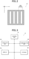
- the multi-slit 12 (G0 grating) is a diffraction grating. As illustrated in FIG. 2 , in the multi-slit 12, multiple slits are formed at predetermined intervals in the x direction, which is orthogonal to the irradiation axis direction (here, the z direction).
- the multi-slit 12 is made of a material having a high radiation absorption rate (i.e., having a high radiation shielding property), such as tungsten, lead, and gold, on a substrate made of a material having a low radiation absorption rate, such as silicon and glass.
- a resist layer is masked in a slit shape by photolithography, and UV is applied to transfer the slit pattern to the resist layer. By exposure, a slit structure having the same shape as the slit pattern is obtained, and a metal is filled between the slit structures by an electroforming method. Thus, the multi-slit 12 is formed.
- the slit period (grating period) of the multi-slit 12 is 1 to 60 ⁇ m.
- One slit period is the distance between adjacent slits, as illustrated in FIG. 2 .
- the width of the slit (the length of each slit in the slit period direction (x direction)) is the length of 1 to 60 % of the slit period, and more preferably 10 to 40 %.
- the height of the slits (the height in the z direction) is 1 to 1500 ⁇ m, and preferably 30 to 1000 ⁇ m.
- the multi-slit 12 is supported by the attachment arm 12b and is attached to the base stand 19.
- the additional filter-collimator 112 limits the irradiation region of the X-rays emitted by the radiation source 11 and removes low-energy components that do not contribute to imaging from the X-rays emitted by the radiation source 11.
- the second cover unit 130 includes the support base 13, the first grating 14, the second grating 15, a moving mechanism 15a, and a radiation detector 16.
- the top surface of the second cover unit 130 serves as the support base 13.
- the side of the support base 13 is covered with a cover member so that the internal constituent elements are protected from damage caused by the contact with the evaluation target H or the engineer or from entry of dust. Since the temperature in the unit is less likely to be affected by the outside air, it is possible to reduce a change in the grating position of the first grating 14 and the second grating 15, which is caused by thermal expansion or the like.
- the support base 13 is a base for supporting the evaluation target H.
- the first grating 14 (G1 grating) is a diffraction grating in which multiple slits are formed in the x direction, which is orthogonal to the z direction as the irradiation axis direction.
- the first grating 14 can be formed by photolithography using UV as with the multi-slit 12, or the grating structure of the first grating 14 may be made of only silicon by a so-called ICP method, by performing deep carving processing on a silicon substrate with fine wires.
- the slit period of the first grating 14 is 1 to 20 ( ⁇ m).
- the width of the slits is 20 to 70 (%) of the slit period and preferably 35 to 60 (%) of the slit period.
- the height of the slits is 1 to 100 ( ⁇ m).
- the second grating 15 is a diffractive grating in which multiple slits are formed in the x direction, which is orthogonal to the z direction as the irradiation axis direction.
- the second grating 15 can also be formed by photolithography.
- the slit period of the second grating 15 is 1 to 20 ( ⁇ m).
- the width of the slits is 30 to 70 (%) of the slit period and preferably 35 to 60 (%) of the slit period.
- the height of the slits is 1 to 100 ( ⁇ m).
- the moving mechanism 15a is provided adjacent to the second grating 15 to move the second grating 15 in the x direction.
- the moving mechanism 15a may have any configuration as long as the movement mechanism 15a can linearly move the second grating 15 in the x direction by driving a motor or the like.
- the radiation detector 16 conversion elements that generate electric signals corresponding to the received radiation are two-dimensionally arranged, and the electric signals generated by the conversion elements are read as image signals.
- the pixel size of the radiation detector 16 is 10 to 300 ( ⁇ m), or more preferably, 50 to 200 ( ⁇ m). It is preferable that the position of the radiation detector 16 be fixed on the base stand 19 so as to abut the second grating 15. This is because the greater the distance between the second grating 15 and the radiation detector 16 is, the more blurry a moire fringe image obtained by the radiation detector 16 becomes.
- an FPD Fluorescence Detector
- an FPD of an indirect conversion type in which radiation is converted into electrical signals by photoelectric conversion elements via a scintillator
- an FPD of a direct conversion type in which radiation is directly converted into electrical signals. Either type may be used.
- a radiation detector to which the intensity modulation effect of the second grating 15 is applied may be used.
- a slit-scintillator detector may be used as the radiation detector 16.
- the slit-scintillator detector is a grading-shaped scintillator that is obtained by forming grooves in a scintillator to provide the scintillator with dead zones having the same periods and widths as the slits of the second grating 15 (reference document 1: Simon Rutishauser et al., "Structured scintillator for hard x-ray grating interferometry", APPLIED PHYSICS LETTERS 98, 171107 (2011)).
- the radiation detector 16 having such a configuration serves as both the second grating 15 and the radiation detector 16, it is not necessary to separately provide the second grating 15. That is, providing the slit scintillator detector is equivalent to providing the second grating 15 and the radiation detector 16.
- the Talbot-Lau interferometer of the main body 1 is a so-called vertical type that emits X-rays from the radiation source 11 provided on the upper side toward the evaluation target H placed on the lower side
- the Talbot-Lau interferometer is not limited thereto.
- the Talbot-Lau interferometer may be configured to emit X-rays from the radiation source 11 provided on the lower side toward the evaluation target H placed on the upper side.
- the Talbot-Lau interferometer can also be configured to emit X-rays in any direction, such as in a horizontal direction (a so-called horizontal type).
- the controller 5 includes a control unit 51, an operation unit 52, a display 53, a communication unit 54, and a storage 55.
- the control unit 51 includes a CPU (central processing unit) and a RAM (random access memory).
- the control unit 51 is connected to the components of the main body 1 (e.g., the radiation source 11, the radiation detector 16, and the moving mechanism 15a) and controls the operation of the components. Furthermore, the control unit 51 performs various kinds of processes including a crack depth calculation process A, which is described later, in cooperation with programs stored in the storage 55.
- control unit 51 functions as a generation means that generates a small-angle scattering image, based on moire fringe images, which are described later. Furthermore, the control unit 51 functions as a calculation means that obtains the scattering signal intensity of the defect part, based on the small-angle scattering image and calculates depth-direction information of the defect part, which is described later, based on the scattering signal intensity.
- the defect part refers to a defect (a crack or the like) generated in the evaluation target H when external energy is applied to the evaluation target H.
- the external energy includes both energy applied intentionally and energy applied unintentionally.
- the former is mainly intended for evaluation tests, and the latter is mainly intended for product tests.
- the operation unit 52 includes a touch screen integrally formed with a display of the display 53, an exposure switch, and a group of keys used for inputting imaging conditions and so forth.
- the operation unit 52 generates operation signals corresponding to the manipulation of these and outputs the operation signals to the control unit 51.
- the display 53 displays an operation screen, an operation status of the main body 1, and so forth on the display in accordance with the display control of the control unit 51.
- the communication unit 54 includes a communication interface and communicates with an external device over the network.
- the storage 55 is constituted of a nonvolatile semiconductor memory, a hard disk, or the like, and stores programs to be executed by the control unit 51 and data necessary for executing the programs.
- the transmitted X-rays form images at regular intervals in the z-direction. These images are called self-images, and a phenomenon of forming the self-images is called a Talbot effect.
- the second grating 15 is arranged substantially parallel to the self-image at the position where the self-image is formed, and a moire fringe image (indicated by Mo in FIG. 4 ) is obtained by the X-rays that have been transmitted by the second grating 15. That is, the first grating 14 forms a periodic pattern, and the second grating 15 converts the periodic pattern into a moire fringe.
- the phase of the X-rays is shifted by the evaluation target H, and the moire fringes on the moire fringe image are disturbed at the edge of the evaluation target H as a boundary, as shown in FIG. 4 .
- the disturbance of the moire fringes is detected by processing the moire fringe image, and the image of the evaluation target H can be imaged. This is the principle of the Talbot interferometer.
- the multi-slit 12 is arranged at a position close to the radiation source 11 between the radiation source 11 and the first grating 14, and X-ray imaging by the Talbot-Lau interferometer is performed.
- the Talbot interferometer is based on the premise that the radiation source 11 is an ideal point source, the focal point in actual imaging has a focal diameter that is large to some extent. Therefore, the multi-slit 12 provides an effect as if X-rays are emitted from consecutive multiple point sources. This is the X-ray imaging method using the Talbot-Lau interferometer. Even when the focal diameter is large to some extent, the Talbot-Lau interferometer can obtain a Talbot effect like a Talbot effect of the Talbot interferometer.
- the main body 1 of the present embodiment obtains moire fringe images, which are necessary for generating a reconstructed image of the evaluation target H, by a fringe scanning method.
- fringe scanning refers to performing M times of imaging (M-Step imaging) while relatively moving one or two (in the present embodiment, the second grating 15) of the gratings (the multi-slit 12, the first grating 14, and the second grating 15) in the slit period direction (x direction) to obtain M moire fringe images necessary for generating a reconstructed image .
- M is a positive integer.
- M satisfies M > 2.
- M satisfies M > 3.
- the slit period of the grating to be moved is d ( ⁇ m)
- imaging is repetitively performed every time the grating is moved in the slit period direction by d/M ( ⁇ m).
- M moire fringe images are obtained.
- the types of the reconstructed image generated based on the moire fringe image include a small-angle scattering image, a differential phase image, and an absorption image.
- the small-angle scattering image shows an image of scattering of X-rays in a microstructure, and the signal intensity increases as the scattering of X-rays increases.
- the small-angle scattering image can show a microstructure aggregate of several ⁇ m to several tens of ⁇ m, which is smaller than the pixel size.
- the differential phase image shows an image of X-rays refracted by the evaluation target H, and the signal intensity increases as the refraction of the X-rays increases.
- the sensitivity becomes lower for lighter elements, whereas in the differential phase image, the sensitivity can be kept high for lighter elements. Therefore, a change in a substance that may not be captured in the absorption image can be captured in the differential phase image.
- the absorption image shows an image of absorption of X-rays by the evaluation target H and is an equivalent to a conventional simple X-ray image.
- the moire fringe images of the evaluation target H are subjected to offset correction processing, gain correction processing, defective pixel correction processing, X-ray intensity fluctuation correction, and so forth, for example.
- a reconstructed image is generated, based on the corrected moire fringe images of the evaluation target H and the background (BG) moire fringe images for generating the reconstructed image.
- the BG moire fringe images are moire fringe images obtained by moving the second grating 15 without the evaluation target H on the support base 13 under the same X-ray irradiation conditions (tube voltage, mAs value, and filter) as the moire fringe images of the evaluation target H.
- an added image of the M moire fringe images of the evaluation target H is divided by an added image of the M BG moire fringe images to generate a transmittance image, and the generated transmittance image is logarithmically converted to the absorption image.
- the phases of moire fringes are calculated for the moire fringe images with the evaluation target H and for the BG moire fringe images, based on the principle of the fringe scanning method to generate a differential phase image with the evaluation target H and a differential phase image without the evaluation target H; and the differential phase image without the evaluation target H is subtracted from the generated differential phase image with the evaluation target H.
- the evaluation target H is a brittle material having a high transmittance (I/Io) of electromagnetic waves including light and having a defect part.
- the transmittance (I/Io) of electromagnetic waves including light is defined by the following Expression (1).
- a brittle material refers to a brittle material that may be cracked, chipped, or deformed by various impact tests.
- Specific examples thereof include: ceramics such as alumina, zirconia, aluminum nitride, mullite, cordierite, alumina/borosilicate glass, cordierite/borosilicate glass, nickel oxide/zirconia, titanium oxide; these ceramic materials to which an oxide of an alkaline earth element, an oxide of a rare earth element, or the like is added; polymer materials such as TAC (tantalum carbide), COP (Cyclo-olefin Polymer), acrylic, polycarbonate, and polyimide; and hard coat materials.
- ceramics such as alumina, zirconia, aluminum nitride, mullite, cordierite, alumina/borosilicate glass, cordierite/borosilicate glass, nickel oxide/zirconia, titanium oxide
- these ceramic materials to which an oxide of an alkaline earth element, an oxide of a rare earth
- a high transmittance refers to a transmittance that allows obtainment of the depth-direction information of the defect part.
- the X-ray transmittance (I/Io) of the evaluation target H be in the range of 0.900 to 0.999 under the imaging condition that the tube voltage is 50 kV and the dose is 800 mAs, for example.
- the X-ray transmittance (I/Io) of the evaluation target H is not necessarily limited to this range.
- the sample may be a brittle material alone (a glass plate or a green sheet of a dielectric ceramic) or may be a brittle material incorporated in a device (an electronic device in which a brittle material is incorporated as a protective member or a multilayer ceramic capacitor).
- UTG ultra-thin glass
- protective member constituted of an UTG to which a protective film is attached
- electronic device a smartphone, a tablet, and so forth
- green sheet of dielectric ceramics titanium oxide, barium titanate, strontium titanate, and so forth
- multilayer ceramic capacitor that includes any of these materials as a dielectric layer.
- FIG. 5 is a flowchart illustrating the crack depth calculation process A that is executed by the control unit 51 of the radiography apparatus 100 in cooperation with a program stored in the storage 55.
- the crack depth calculation process A is a process to calculate the depth-direction information of the defect part (crack) of the evaluation target H.
- the evaluation target H has already been subjected to a pen drop test (e.g., disclosed in Japanese Translation of PCT International Publication 2020-537185 ) and that the defect part (crack) has been formed by the pen drop in the evaluation target H .
- a calibration curve which is described later, has already been stored in the storage 55.
- M e.g., four moire fringe images without the evaluation target H (referred to as BG moire fringe images) are obtained and stored in the storage 55 before starting the crack depth calculation process A.
- the BG moire fringe images are obtained by performing imaging while moving the second grating 15 in a state where the evaluation target H is not set on the support base 13 or both the evaluation target H and the support base 13 are removed.
- the crack depth calculation process A is executed in response to the operation unit 52 receiving an execution instruction.
- the evaluation target H is set on the support base 13 before Step S2.
- control unit 51 obtains test conditions via the operation unit 52 (Step S1). For example, the control unit 51 obtains the height from which the pen is dropped in the pen drop test.
- the control unit 51 performs imaging (referred to as Talbot imaging) to obtain moire fringe images using the above-described Talbot effect by controlling the radiation source 11, the moving mechanism 15a, the radiation detector 16, and so forth.
- M moire fringe images with the evaluation target H (referred to as evaluation target H moire fringe images) are obtained while moving the grating (the second grating 15 in this embodiment) in the slit period direction by the fringe scanning method.
- the control unit 51 Based on the BG fringe moire images, which have been obtained beforehand, and the evaluation target H moire fringe images, the control unit 51 generates a small-angle scattering image as a reconstructed image (Step S2).
- the control unit 51 extracts the scattering signal intensity of the small-angle scattering image of the defect part (Step S3). Since the defect part is a part and its surrounding on which the pen was dropped in the pen drop test, the defect part is known.
- the defect part may be a part where the scattering signal intensity is equal to or greater than a threshold.
- control unit 51 calculates the crack depth of the defect part, based on the calibration curve created beforehand in the storage 55 (Step S4).
- the calibration curve and the method of calculating the crack depth using the calibration curve are described below.
- the calibration curve refers to a graph curve representing the relationship between the crack depth in the depth direction and the scattering signal intensity. That is, once the scattering signal intensity is obtained, the crack depth corresponding to the value of the scattering signal intensity is obtained.
- the calibration curve can be created as follows: Talbot imaging is performed on glass plates having grooves of different known depths, or Talbot imaging is performed on pieces of a brittle material having different thicknesses and arranged so as to align on their lateral sides to obtain the scattered signal intensities at the connection portions between the pieces of the brittle material; and the scattered signal intensities corresponding to the groove depths are obtained.
- the evaluation target H is a brittle material having a high transmittance (I/Io) of electromagnetic waves including light. Therefore, the scattering signal intensity includes only information on cracks, as shown in FIG. 6 , and a calibration curve can be created.
- the scattering signal intensity includes not only information on cracks but also information on fibers and voids. Therefore, the calibration curve cannot be created.
- connection portions mentioned above may not only be the glued portions between the glass plates or pieces of the brittle material arranged such that their edges are aligned but also the contacted portions between the glass plates or pieces of the brittle material arranged such that their edges are aligned.
- control unit 51 causes the display 53 to display the drop height of the pen in the pen drop test and the crack depth of the defect part (Step S5).
- the control unit 51 then ends the crack depth calculation process A.
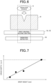
- FIG. 7 is a graph in which crack depths and drop heights are plotted.
- the crack depths were obtained by performing the pen drop test of dropping a pen from three different heights and by performing the crack depth calculation process A of FIG. 5 three times.
- the solid straight line approximately shows the relationship between the crack depth and the drop height, based on the plotted points. For example, a straight line obtained by least square approximation may be used.
- the broken line indicates the thickness of the evaluation target H.
- the drop height at the intersection of the solid line and the broken line is used as an index related to the impact resistance of the evaluation target H.
- the impact resistance performance can be quantitatively evaluated.
- FIG. 11 shows results of a known test.
- samples of the evaluation target H having different thicknesses are prepared; the samples are visually inspected whether the samples are cracked or not each time the drop height is changed; and thus the impact resistance performance of the evaluation target H is checked.
- the impact resistance performance can be evaluated by performing a test by a smaller number of times.
- the drop height at the intersection of the solid line and the broken line is used as an index related to the impact resistance of the evaluation target H.
- the index is not limited thereto.
- the crack depths obtained for the respective evaluation targets H are used as indexes.
- the strengths of the respective evaluation targets H can be relatively evaluated.
- the evaluation targets H can also be classified into strength grades that are determined based on crack depths as indexes.
- an impact pressure applied to the evaluation target H when a pen hits the evaluation target H in the pen drop test may be used as an index related to impact resistance.
- a base layer, a pressure-sensitive paper, and the evaluation target H are arranged in this order on a surface plate; a pen drop test is performed in this state; and the discoloration of part of the pressure-sensitive paper where the pen was dropped is measured by a pressure image analysis system, for example.
- the base layer is made of a resin material, such as polyimide, acryl, or Bakelite, for example.
- the base layer may be an actual electronic device module to which the evaluation target H is attached as a cover.
- the radiation source 11 may emit radiation rays having multiple wavelengths.
- the accuracy of crack depth calculation can be improved.
- the scattering signal intensity obtained by imaging the angled evaluation target H may be used alone or used in combination to calculate the crack depth.
- the pen drop test is performed as an example in the first embodiment, a bending test (e.g., disclosed in Japanese Unexamined Patent Publication No. 2018-92770 ), a tensile test (e.g., disclosed in Japanese Unexamined Patent Publication No. 2020-187088 ), or the like may be performed.
- a bending test e.g., disclosed in Japanese Unexamined Patent Publication No. 2018-92770
- a tensile test e.g., disclosed in Japanese Unexamined Patent Publication No. 2020-187088
- the load indicates the impact resistance performance of the evaluation target H.
- the crack depth is calculated based on the scattering signal intensity of the small-angle scattering image in the first embodiment, the crack depth may be calculated based on the signal intensity of the differential phase image.
- the signal intensity of the differential phase image represents the refraction of X-rays in the evaluation target H, as described above, and the degree of the refraction of X-rays changes depending on the crack depth. Therefore, it is possible to prepare a calibration curve of the signal intensity of the differential phase image and the crack depth, based on the same method in the paragraph [0047]. That is, once the signal intensity of the differential phase image is obtained, the crack depth corresponding to the signal intensity of the differential phase image is obtained.
- an Optical Talbot device 200 shown in FIG. 8 includes a laser 21, a biconcave lens 22, a mirror 23, a plano-convex lens 24, a first grating 14 (G1 grating), a second grating 15 (G2 grating), a screen 25, and a CCD (Charge -Coupled Device) camera 26.
- the laser light is expanded by the biconcave lens 22, the mirror 23, and the plano-convex lens 24, and the evaluation target H is placed between the plano-convex lens 24 and the Talbot interferometer (the first grating 14, the second grating 15, the screen 25, and the CCD camera 26).
- the optical Talbot device 200 forms a moire fringe image including moire fringe disturbance on the screen 25 and obtains a small-angle scattering image and a differential phase image of the evaluation target H by processing the moire fringe image.
- the evaluation method for evaluating a brittle material uses a Talbot imaging apparatus (radiography apparatus 100).
- the evaluation target H is a brittle material having a high transmittance (I/Io) of an electromagnetic wave including light and having a defect part.
- the method includes: imaging the evaluation target H to obtain a small-angle scattering image; obtaining a scattering signal intensity of the defect part from the small-angle scattering image; and calculating depth-direction information of the defect part from the scattering signal intensity. Therefore, the entire defect part in a brittle material having a high transmittance and the defect part can be quantitatively evaluated.
- the depth-direction information is calculated, based on a calibration curve of the scattering signal intensity and depth information of the defect part of the evaluation target H. Therefore, the entire defect part in a brittle material having a high transmittance and the defect part can be quantitatively and quickly evaluated.
- the test has to be performed many times, as shown in the known test result in FIG. 11 .
- an index related to an impact resistance of the evaluation target H is quantitatively calculated, based on the depth-direction information. Therefore, the entire defect part in a brittle material having a high transmittance and the defect part can be quantitatively evaluated.
- the defect part in the evaluation target H is generated by a pen drop test. Therefore, the entire defect part of the evaluation target H subjected to a known testing method can be quantitatively evaluated.
- the defect part of the evaluation target H is generated by a bending test. Therefore, the entire defect part of the evaluation target H subjected to a known testing method can be quantitatively evaluated.
- the X-ray transmittance (I/Io) of the evaluation target H be in a range of 0.900 to 0.999 in a situation that the evaluation target H is imaged under conditions that the tube voltage is 50 kV and the radiation dose is 800 mAs. With such an evaluation target H, the entire defect part thereof can be appropriately evaluated.
- an evaluation method uses a Talbot imaging apparatus (radiography apparatus 100).
- the evaluation target H is a brittle material having a high transmittance (I/Io) of an electromagnetic wave including light and having a defect part.
- the method includes: imaging the evaluation target H to obtain a differential phase image; obtaining a signal intensity of the defect part from the differential phase image; and calculating depth-direction information of the defect part from the signal intensity. Therefore, the entire defect part in a brittle material having a high transmittance and the defect part can be quantitatively evaluated.
- an evaluation apparatus includes: an irradiation device (radiation source 11) that emits an electromagnetic wave including light; gratings (the multi-slit 12, the first grating 14, and the second grating 15); a detector (the radiation detector 16); a generation means (the control unit 51); and a calculation means (the control unit 51).
- the irradiation deice, the gratings, and the detector are arranged in an irradiation axis direction.
- the evaluation target H is a brittle material that has a high transmittance (I/Io) of the electromagnetic wave and that has a defect part, and the evaluation target H is placed at a position overlapping the irradiation axis direction.
- the irradiation device irradiates the evaluation target H to image the evaluation target H and obtain a moire fringe image(s).
- the generation means generates a small-angle scattering image, based on the obtained moire fringe image.
- the calculation means obtains a scattering signal intensity of the defect part from the small-angle scattering image and calculates depth-direction information of the defect part from the scattering signal intensity. Therefore, the entire defect part in a brittle material having a high transmittance and the defect part can be quantitatively evaluated.
- the calculation means calculates the depth-direction information, based on a calibration curve of the scattering signal intensity and depth information of the defect part of the evaluation target H. Therefore, the entire defect part in a brittle material having a high transmittance and the defect part can be quantitatively and quickly evaluated.
- the calculation means (control unit 51) quantitatively calculates an index related to the impact resistance of the evaluation target H, based on the depth-direction information. Therefore, the entire defect part in a brittle material having a high transmittance and the defect part can be quantitatively evaluated.
- a program is for a computer of an evaluation apparatus that includes an irradiation device (the radiation source 11) for emitting an electromagnetic wave including light, gratings (the multi-slit 12, the first grating 14, and the second grating 15), and a detector (the radiation detector 16).
- the irradiation device, the gratings, and the detector are arranged in an irradiation axis direction.
- the evaluation target H is a brittle material that has a high transmittance (I/Io) of the electromagnetic wave and has a defect part, and the evaluation target H is placed at a position overlapping the irradiation axis direction.
- the irradiation device irradiates the evaluation target to image the evaluation target H and obtain a moire fringe image(s).
- the evaluation apparatus evaluates the evaluation target H, based on the obtained moire fringe image.
- the program causes the computer to function as: a generation means (the control unit 51) that generates a small-angle scattering image, based on the moire fringe image; and a calculation means (the control unit 51) that obtains a scattering signal intensity of the defect part from the small-angle scattering image and calculates depth-direction information of the defect part from the scattering signal intensity. Therefore, the entire defect part in a brittle material having a high transmittance and the defect part can be quantitatively evaluated.
- the entire defect part can be quantitatively evaluated by performing the same test as in the first embodiment of the present invention, obtaining the signal intensity of the defect part from the differential phase image, and calculating the depth-direction information of the defect part.
- the evaluation apparatus in the above-described embodiment uses the Talbot-Lau interferometer that moves the second grating 15 with respect to the multi-slit 12 and the first grating 14 during imaging by the fringe scanning method, as an example.
- the present invention may be applied to an evaluation apparatus that uses a Talbot-Lau interferometer that moves one or two gratings among the multi-slit 12, the first grating 14, and the second grating 15 during imaging by the fringe scanning method.
- the present invention may be applied to an evaluation apparatus that uses a Talbot interferometer that moves either the first grating 14 or the second grating 15 with respect to the other grating.
- the present invention may be applied to an evaluation apparatus that uses a Lau interferometer that moves either the multi-slit 12 or the first grating 14 with respect to the other grating. Furthermore, the present invention may be applied to a Talbot-Lau interferometer, a Talbot interferometer, or a Lau interferometer that uses a Fourier transform method, which does not require fringe scanning.
- the small-angle scattering image and the differential phase image are generated based on the moire fringe images obtained by the Talbot imaging, as an example.
- the present invention can be realized as long as the small-angle scattering image and/or the differential phase image are generated.
- a hard disk or a semiconductor nonvolatile memory is used as examples of a computer-readable medium for the program according to the present invention
- the computer-readable storage medium is not limited to these examples.
- portable recording media such as CD-ROMs can be applied.
- a carrier wave is also applied as a medium for providing data of the program according to the present invention via a communication line.
- the present disclosure can be used as an evaluation method, an evaluation apparatus, and a program.
Landscapes
- Chemical & Material Sciences (AREA)
- Health & Medical Sciences (AREA)
- Biochemistry (AREA)
- Physics & Mathematics (AREA)
- Life Sciences & Earth Sciences (AREA)
- Analytical Chemistry (AREA)
- General Health & Medical Sciences (AREA)
- General Physics & Mathematics (AREA)
- Immunology (AREA)
- Pathology (AREA)
- Crystallography & Structural Chemistry (AREA)
- Nuclear Medicine, Radiotherapy & Molecular Imaging (AREA)
- Radiology & Medical Imaging (AREA)
- Analysing Materials By The Use Of Radiation (AREA)
Abstract
Description
- The present invention relates to an evaluation method, an evaluation apparatus, and a program.
- Glass is a typical brittle material and has excellent transparency, chemical resistance, and heat resistance. Thus, glass is suitable for applications where defined chemical and physical properties are important. Examples of such applications include displays, various sensors, solar cells, and micromechanical parts.
- Recently, there has been a demand for further improvement in quality of glass, and a thinner and lighter glass substrate having high strength and flexibility has been awaited.
- Ultra-thin glass (UTG) has been developed as a cover glass and display for devices such as smart phones, tablets, watches and other wearable devices due to its flexibility. The UTG can also be used as a cover glass of a fingerprint sensor module and a lens cover of a camera.
- However, a glass sheet that is less than 0.5 mm thick like UTG tends to have defects that mainly result in breakage, such as cracks and chipping at the glass edge. Handling of such a glass sheet is tremendously difficult. Also, a thinner glass sheet results in a significant decrease of the overall mechanical strength (i.e., bending or impact strength).
- Therefore, it is very important to estimate the strength of a thin glass and to estimate whether the thin glass product can be used for a particular application. To evaluate the mechanical properties of ultrathin glass, many tests have been developed. Specific examples of the tests include a three-point bending (3BP) test, a pen drop test, and a scratch resistance test.
- In a known pen drop test, a pen is dropped to hit a glass, and it is determined whether the glass is broken or not, based on qualitative evaluation by visual observation. According to the visual evaluation, it is possible to confirm that the glass is broken, but it is not possible to determine to what extent the glass is broken in the thickness direction. That is, in a case where the glass is used for a protective cover, it is not possible to determine whether the damage has reached the product to be protected.
- When an optical system, such as a white light interferometer or a laser microscope, is used, a field of view is narrowed in a high magnification observation, as shown in
FIG. 9(b) as an example. There is no method for comprehensively and quantitatively evaluating the entire crack other than visual observation. - As a method for comprehensively evaluating such cracks,
Patent Document 1 discloses a method for visualizing a two-dimensional size of a cracks and a void and distribution of cracks and voids generated inside a test piece made of resin and CFRP (Carbon Fiber Reinforced Plastics) by a tensile test, by using a small-angle scattering image and a differential phase image generated by X-ray Talbot imaging. - Patent literature 1:
Japanese Unexamined Patent Publication No. 2020-187088 - However, although the method of
Patent Document 1 can clarify the two-dimensional size and in-plane distribution of cracks and voids, these are all limited to two-dimensional information. That is, it is not possible to quantitatively learn depth-direction information of the crack (to what extent the sample is cracked in the thickness direction) only by generating the small-angle scattering image and the differential phase image and visualizing the entire crack generated in the sample, as disclosed inPatent Document 1. - More specifically, according to the invention described in
Patent Document 1, when the sample is a fiber-oriented resin such as CFRP, X-rays are scattered not only at the position of the generated crack but also at a fiber portion h in the evaluation target H, as shown inFIG. 10 . Since the Talbot imaging generates a small-angle scattering image by integrating the scattering signal intensity in the X-ray radiation axis direction, it is not possible to extract the scattering signal of the crack portion only. It is therefore not possible to calculate the depth of the crack, based on the signal intensity of the small-angle scattering image. - The same applies to the differential phase image, in which the signal intensity changes according to the refraction of the X-rays. In a fiber-oriented resin such as CFRP, X-rays are refracted not only at the position of a generated crack but also at the fiber portion h of the evaluation target H, as shown in
FIG. 10 . Therefore, it is not possible to extract the signal of the crack portion only and to calculate the depth of the crack, based on the signal intensity of the differential phase image. - An object of the present invention is to provide an evaluation method, an evaluation apparatus, and a program that allow quantitative evaluation of the entire defect part in a brittle material having a high transmittance.
- In order to solve the above-described problem, according to the present invention, there is provided a evaluation method using a Talbot imaging apparatus, herein in the evaluation, an evaluation target is a brittle material having a high transmittance (I/Io) of an electromagnetic wave including light and having a defect part, the method including: imaging the evaluation target to obtain a small-angle scattering image; obtaining a scattering signal intensity of the defect part from the small-angle scattering image; and calculating depth-direction information of the defect part from the scattering signal intensity.
- Furthermore, according to the present invention, there is provided an evaluation method using a Talbot imaging apparatus, wherein in the evaluation, an evaluation target is a brittle material having a high transmittance (I/Io) of an electromagnetic wave including light and having a defect part, the method including: imaging the evaluation target to obtain a small-angle scattering image; obtaining a scattering signal intensity of the defect part from the small-angle scattering image; and calculating depth-direction information of the defect part from the scattering signal intensity.
- Furthermore, according to the present invention, there is provided an evaluation apparatus including: an irradiation device that emits an electromagnetic wave including light; gratings; a detector; a generation means; and a calculation means, wherein the irradiation device, the gratings, and the detector are arranged in an irradiation axis direction, wherein an evaluation target is a brittle material that has a high transmittance (I/Io) of the electromagnetic wave and that has a defect part, and the evaluation target is placed at a position overlapping the irradiation axis direction, wherein the irradiation device irradiates the evaluation target to image the evaluation target and obtain a moire fringe image, wherein the generation means generates a small-angle scattering image, based on the obtained moire fringe image, wherein the calculation means obtains a scattering signal intensity of the defect part from the small-angle scattering image and calculates depth-direction information of the defect part from the scattering signal intensity.
- Furthermore, according to the present invention, there is provided a program for a computer of an evaluation apparatus that includes an irradiation device for emitting an electromagnetic wave including light, gratings, and a detector, wherein the irradiation device, the gratings, and the detector are arranged in an irradiation axis direction, wherein an evaluation target is a brittle material that has a high transmittance (I/Io) of the electromagnetic wave and has a defect part, and the evaluation target is placed at a position overlapping the irradiation axis direction, wherein the irradiation device irradiates the evaluation target to image the evaluation target and obtain a moire fringe image, wherein the evaluation apparatus evaluates the evaluation target, based on the obtained moire fringe image, wherein the program causes the computer to function as: a generation means that generates a small-angle scattering image, based on the moire fringe image, and a calculation means that obtains a scattering signal intensity of the defect part from the small-angle scattering image and calculates depth-direction information of the defect part from the scattering signal intensity.
- According to the present invention, the entire defect part in a brittle material having a high transmittance can be quantitatively evaluated.
-
- [
FIG. 1 ] This is a diagram illustrating a configuration example of a radiography apparatus. - [
FIG. 2 ] This is a plan view of a multi slit. - [
FIG. 3 ] This is a block diagram illustrating a functional configuration of a controller. - [
FIG. 4 ] This is a diagram illustrating the principle of a Talbot interferometer. - [
FIG. 5 ] This is a flowchart illustrating a crack depth calculation process. - [
FIG. 6 ] This is a schematic diagram of an evaluation target and a radiography apparatus when viewed from a lateral side. - [
FIG. 7 ] This is a diagram illustrating a result of an impact resistance performance test. - [
FIG. 8 ] This is a diagram illustrating an example of the configuration of a radiography apparatus. - [
FIG. 9 ] This is a diagram illustrating a UTG after a pen drop test. - [
FIG. 10 ] This is a schematic diagram of a known evaluation target and a known radiography apparatus as viewed from a lateral side. - [
FIG. 11 ] This shows a result of a known pen drop test. - Hereinafter, embodiments of the present invention will be described with reference to the drawings.
-
FIG. 1 is a schematic diagram of aradiography apparatus 100 according to a first embodiment of the present invention. - The
radiography apparatus 100 is an apparatus that images an evaluation target H, such as a test piece on which a pen drop test was performed. Theradiography apparatus 100 functions as a Talbot imaging apparatus and an evaluation apparatus. - As illustrated in
FIG. 1 , theradiography apparatus 100 includes amain body 1 and acontroller 5. - As illustrated in
FIG. 1 , themain body 1 includes a Talbot-Lau interferometer that includes: afirst cover unit 120 including aradiation source 11, a multi-slit 12, and an additional filter-collimator 112; asecond cover unit 130 including asupport base 13, afirst grating 14, asecond grating 15, and aradiation detector 16; asupport column 17; and abase stand 19. The Talbot-Lau interferometer of themain body 1 is a vertical type, and theradiation source 11, the multi-slit 12, thesupport base 13, thefirst grating 14, thesecond grating 15, and theradiation detector 16 are arranged in this order in the z direction that is the gravity direction. - The multi-slit 12, the
support base 13, thefirst grating 14, thesecond grating 15, and theradiation detector 16 are supported by thesame base stand 19 and attached to thesupport column 17. Thebase stand 19 may be configured to be movable in the z-direction with respect to thesupport column 17. - In addition to the
base stand 19, theradiation source 11 is attached to thesupport column 17. Theradiation source 11 is supported by thesupport column 17 via thebuffer member 17a. Thebuffer member 17a may be made of any material that can absorb impact and vibration, such as elastomer. Since theradiation source 11 generates heat by emitting radiation, it is preferable that thebuffer member 17a on theradiation source 11 side be made of a material having an insulation property in addition to the impact absorption property. - The
radiation source 11 includes an X-ray tube, generates X-rays with the X-ray tube, and emits the X-rays in the z direction (the gravity direction). As the X-ray tube, a Coolidge X-ray tube or a rotating anode X-ray tube can be used, for example. As the anode, tungsten or molybdenum can be used. - The focal diameter of the
radiation source 11 is preferably 0.03 to 3 (mm), and more preferably 0.1 to 1 (mm). - Although X-rays are used in imaging as an example in the present embodiment, other radiation may be used. For example, neutron rays, gamma rays, or electromagnetic waves including light may be used. That is, in the present embodiment, radiation means radiation in a broad sense and refers to all electromagnetic waves and particle beams.
- The
radiation source 11 functions as an irradiation device. - The
first cover unit 120 is provided immediately below theradiation source 11. As illustrated inFIG. 1 , thefirst cover unit 120 includes the multi-slit 12, anattachment arm 12b, and the additional filter-collimator 112. The constituent elements of thefirst cover unit 120 are covered and protected by a cover member. - The multi-slit 12 (G0 grating) is a diffraction grating. As illustrated in
FIG. 2 , in the multi-slit 12, multiple slits are formed at predetermined intervals in the x direction, which is orthogonal to the irradiation axis direction (here, the z direction). The multi-slit 12 is made of a material having a high radiation absorption rate (i.e., having a high radiation shielding property), such as tungsten, lead, and gold, on a substrate made of a material having a low radiation absorption rate, such as silicon and glass. For example, a resist layer is masked in a slit shape by photolithography, and UV is applied to transfer the slit pattern to the resist layer. By exposure, a slit structure having the same shape as the slit pattern is obtained, and a metal is filled between the slit structures by an electroforming method. Thus, the multi-slit 12 is formed. - The slit period (grating period) of the multi-slit 12 is 1 to 60 µm. One slit period is the distance between adjacent slits, as illustrated in
FIG. 2 . The width of the slit (the length of each slit in the slit period direction (x direction)) is the length of 1 to 60 % of the slit period, and more preferably 10 to 40 %. The height of the slits (the height in the z direction) is 1 to 1500 µm, and preferably 30 to 1000 µm. The multi-slit 12 is supported by theattachment arm 12b and is attached to thebase stand 19. - The additional filter-
collimator 112 limits the irradiation region of the X-rays emitted by theradiation source 11 and removes low-energy components that do not contribute to imaging from the X-rays emitted by theradiation source 11. - As shown in
FIG. 1 , thesecond cover unit 130 includes thesupport base 13, thefirst grating 14, thesecond grating 15, a movingmechanism 15a, and aradiation detector 16. The top surface of thesecond cover unit 130 serves as thesupport base 13. The side of thesupport base 13 is covered with a cover member so that the internal constituent elements are protected from damage caused by the contact with the evaluation target H or the engineer or from entry of dust. Since the temperature in the unit is less likely to be affected by the outside air, it is possible to reduce a change in the grating position of thefirst grating 14 and thesecond grating 15, which is caused by thermal expansion or the like. - The
support base 13 is a base for supporting the evaluation target H. - As with the multi-slit 12, the first grating 14 (G1 grating) is a diffraction grating in which multiple slits are formed in the x direction, which is orthogonal to the z direction as the irradiation axis direction. The
first grating 14 can be formed by photolithography using UV as with the multi-slit 12, or the grating structure of thefirst grating 14 may be made of only silicon by a so-called ICP method, by performing deep carving processing on a silicon substrate with fine wires. The slit period of thefirst grating 14 is 1 to 20 (µm). The width of the slits is 20 to 70 (%) of the slit period and preferably 35 to 60 (%) of the slit period. The height of the slits is 1 to 100 (µm). - As with the multi-slit 12, the second grating 15 (G2 grating) is a diffractive grating in which multiple slits are formed in the x direction, which is orthogonal to the z direction as the irradiation axis direction. The
second grating 15 can also be formed by photolithography. The slit period of thesecond grating 15 is 1 to 20 (µm). The width of the slits is 30 to 70 (%) of the slit period and preferably 35 to 60 (%) of the slit period. The height of the slits is 1 to 100 (µm). The movingmechanism 15a is provided adjacent to thesecond grating 15 to move thesecond grating 15 in the x direction. The movingmechanism 15a may have any configuration as long as themovement mechanism 15a can linearly move thesecond grating 15 in the x direction by driving a motor or the like. - In the
radiation detector 16, conversion elements that generate electric signals corresponding to the received radiation are two-dimensionally arranged, and the electric signals generated by the conversion elements are read as image signals. The pixel size of theradiation detector 16 is 10 to 300 (µm), or more preferably, 50 to 200 (µm). It is preferable that the position of theradiation detector 16 be fixed on the base stand 19 so as to abut thesecond grating 15. This is because the greater the distance between thesecond grating 15 and theradiation detector 16 is, the more blurry a moire fringe image obtained by theradiation detector 16 becomes. - As the
radiation detector 16, an FPD (Flat Panel Detector) can be used. There are an FPD of an indirect conversion type in which radiation is converted into electrical signals by photoelectric conversion elements via a scintillator and an FPD of a direct conversion type in which radiation is directly converted into electrical signals. Either type may be used. - As the
radiation detector 16, a radiation detector to which the intensity modulation effect of thesecond grating 15 is applied may be used. For example, a slit-scintillator detector may be used as theradiation detector 16. The slit-scintillator detector is a grading-shaped scintillator that is obtained by forming grooves in a scintillator to provide the scintillator with dead zones having the same periods and widths as the slits of the second grating 15 (reference document 1: Simon Rutishauser et al., "Structured scintillator for hard x-ray grating interferometry", APPLIED PHYSICS LETTERS 98, 171107 (2011)). Since theradiation detector 16 having such a configuration serves as both thesecond grating 15 and theradiation detector 16, it is not necessary to separately provide thesecond grating 15. That is, providing the slit scintillator detector is equivalent to providing thesecond grating 15 and theradiation detector 16. - Although the Talbot-Lau interferometer of the
main body 1 is a so-called vertical type that emits X-rays from theradiation source 11 provided on the upper side toward the evaluation target H placed on the lower side, the Talbot-Lau interferometer is not limited thereto. The Talbot-Lau interferometer may be configured to emit X-rays from theradiation source 11 provided on the lower side toward the evaluation target H placed on the upper side. The Talbot-Lau interferometer can also be configured to emit X-rays in any direction, such as in a horizontal direction (a so-called horizontal type). - As illustrated in
FIG. 3 , thecontroller 5 includes acontrol unit 51, anoperation unit 52, adisplay 53, acommunication unit 54, and astorage 55. - The
control unit 51 includes a CPU (central processing unit) and a RAM (random access memory). Thecontrol unit 51 is connected to the components of the main body 1 (e.g., theradiation source 11, theradiation detector 16, and the movingmechanism 15a) and controls the operation of the components. Furthermore, thecontrol unit 51 performs various kinds of processes including a crack depth calculation process A, which is described later, in cooperation with programs stored in thestorage 55. - That is, the
control unit 51 functions as a generation means that generates a small-angle scattering image, based on moire fringe images, which are described later. Furthermore, thecontrol unit 51 functions as a calculation means that obtains the scattering signal intensity of the defect part, based on the small-angle scattering image and calculates depth-direction information of the defect part, which is described later, based on the scattering signal intensity. - Here, the defect part refers to a defect (a crack or the like) generated in the evaluation target H when external energy is applied to the evaluation target H. The external energy includes both energy applied intentionally and energy applied unintentionally. The former is mainly intended for evaluation tests, and the latter is mainly intended for product tests.
- The
operation unit 52 includes a touch screen integrally formed with a display of thedisplay 53, an exposure switch, and a group of keys used for inputting imaging conditions and so forth. Theoperation unit 52 generates operation signals corresponding to the manipulation of these and outputs the operation signals to thecontrol unit 51. - The
display 53 displays an operation screen, an operation status of themain body 1, and so forth on the display in accordance with the display control of thecontrol unit 51. - The
communication unit 54 includes a communication interface and communicates with an external device over the network. - The
storage 55 is constituted of a nonvolatile semiconductor memory, a hard disk, or the like, and stores programs to be executed by thecontrol unit 51 and data necessary for executing the programs. - An imaging method by the Talbot interferometer and the Talbot-Lau interferometer is described.
- As shown in
FIG. 4 , when the X-rays emitted by theradiation source 11 are transmitted through thefirst grating 14, the transmitted X-rays form images at regular intervals in the z-direction. These images are called self-images, and a phenomenon of forming the self-images is called a Talbot effect. Thesecond grating 15 is arranged substantially parallel to the self-image at the position where the self-image is formed, and a moire fringe image (indicated by Mo inFIG. 4 ) is obtained by the X-rays that have been transmitted by thesecond grating 15. That is, thefirst grating 14 forms a periodic pattern, and thesecond grating 15 converts the periodic pattern into a moire fringe. When the evaluation target H is present between theradiation source 11 and thefirst grating 14, the phase of the X-rays is shifted by the evaluation target H, and the moire fringes on the moire fringe image are disturbed at the edge of the evaluation target H as a boundary, as shown inFIG. 4 . The disturbance of the moire fringes is detected by processing the moire fringe image, and the image of the evaluation target H can be imaged. This is the principle of the Talbot interferometer. - In the
main body 1, the multi-slit 12 is arranged at a position close to theradiation source 11 between theradiation source 11 and thefirst grating 14, and X-ray imaging by the Talbot-Lau interferometer is performed. Although the Talbot interferometer is based on the premise that theradiation source 11 is an ideal point source, the focal point in actual imaging has a focal diameter that is large to some extent. Therefore, the multi-slit 12 provides an effect as if X-rays are emitted from consecutive multiple point sources. This is the X-ray imaging method using the Talbot-Lau interferometer. Even when the focal diameter is large to some extent, the Talbot-Lau interferometer can obtain a Talbot effect like a Talbot effect of the Talbot interferometer. - The
main body 1 of the present embodiment obtains moire fringe images, which are necessary for generating a reconstructed image of the evaluation target H, by a fringe scanning method. In general, fringe scanning refers to performing M times of imaging (M-Step imaging) while relatively moving one or two (in the present embodiment, the second grating 15) of the gratings (the multi-slit 12, thefirst grating 14, and the second grating 15) in the slit period direction (x direction) to obtain M moire fringe images necessary for generating a reconstructed image . M is a positive integer. For an absorption image, M satisfies M > 2. For a differential phase image and a small-angle scattering image, M satisfies M > 3. Specifically, assuming that the slit period of the grating to be moved is d (µm), imaging is repetitively performed every time the grating is moved in the slit period direction by d/M (µm). Thus, M moire fringe images are obtained. - The types of the reconstructed image generated based on the moire fringe image include a small-angle scattering image, a differential phase image, and an absorption image.
- The small-angle scattering image shows an image of scattering of X-rays in a microstructure, and the signal intensity increases as the scattering of X-rays increases. The small-angle scattering image can show a microstructure aggregate of several µm to several tens of µm, which is smaller than the pixel size.
- The differential phase image shows an image of X-rays refracted by the evaluation target H, and the signal intensity increases as the refraction of the X-rays increases. In the absorption image, the sensitivity becomes lower for lighter elements, whereas in the differential phase image, the sensitivity can be kept high for lighter elements. Therefore, a change in a substance that may not be captured in the absorption image can be captured in the differential phase image.
- The absorption image shows an image of absorption of X-rays by the evaluation target H and is an equivalent to a conventional simple X-ray image.
- To generate the reconstructed image, firstly, the moire fringe images of the evaluation target H (the moire fringe image with the evaluation target H) are subjected to offset correction processing, gain correction processing, defective pixel correction processing, X-ray intensity fluctuation correction, and so forth, for example. Next, a reconstructed image is generated, based on the corrected moire fringe images of the evaluation target H and the background (BG) moire fringe images for generating the reconstructed image. The BG moire fringe images are moire fringe images obtained by moving the
second grating 15 without the evaluation target H on thesupport base 13 under the same X-ray irradiation conditions (tube voltage, mAs value, and filter) as the moire fringe images of the evaluation target H. - To generate the absorption image, an added image of the M moire fringe images of the evaluation target H is divided by an added image of the M BG moire fringe images to generate a transmittance image, and the generated transmittance image is logarithmically converted to the absorption image.
- To generate the differential phase image, the phases of moire fringes are calculated for the moire fringe images with the evaluation target H and for the BG moire fringe images, based on the principle of the fringe scanning method to generate a differential phase image with the evaluation target H and a differential phase image without the evaluation target H; and the differential phase image without the evaluation target H is subtracted from the generated differential phase image with the evaluation target H.
- To generate the small-angle scattering image, the visibility of moire fringes is calculated for the moire fringe images with the evaluation target H and for the BG moire fringe images (visibility = amplitude/average value), based on the principle of the fringe scanning method to generate a small-angle scattering image with the evaluation target H and a small-angle scattering image without the evaluation target H; and the generated small-angle scattering image with the evaluation target H is divided by the small-angle scattering image without the evaluation target H.
- The evaluation target H is a brittle material having a high transmittance (I/Io) of electromagnetic waves including light and having a defect part.
- The transmittance (I/Io) of electromagnetic waves including light is defined by the following Expression (1). The transmittance is determined by the ratio I/Io between the incident irradiation energy Io and the irradiation energy I transmitted by a substance.
[Expression 1]
- µ: Linear attenuation coefficient
- ρ: Density of a substance to be irradiated with X-rays
- x: Mass thickness of a substance to be irradiated with X-rays
- A brittle material refers to a brittle material that may be cracked, chipped, or deformed by various impact tests. Specific examples thereof include: ceramics such as alumina, zirconia, aluminum nitride, mullite, cordierite, alumina/borosilicate glass, cordierite/borosilicate glass, nickel oxide/zirconia, titanium oxide; these ceramic materials to which an oxide of an alkaline earth element, an oxide of a rare earth element, or the like is added; polymer materials such as TAC (tantalum carbide), COP (Cyclo-olefin Polymer), acrylic, polycarbonate, and polyimide; and hard coat materials.
- When the transmittance is low, X-rays scatter greatly in parts other than the defect part, and the depth-direction information of the defect part cannot be obtained. Therefore, a high transmittance refers to a transmittance that allows obtainment of the depth-direction information of the defect part.
- Specifically, it is preferable that the X-ray transmittance (I/Io) of the evaluation target H be in the range of 0.900 to 0.999 under the imaging condition that the tube voltage is 50 kV and the dose is 800 mAs, for example. However, the X-ray transmittance (I/Io) of the evaluation target H is not necessarily limited to this range.
- As the form of a sample in actual imaging, the sample may be a brittle material alone (a glass plate or a green sheet of a dielectric ceramic) or may be a brittle material incorporated in a device (an electronic device in which a brittle material is incorporated as a protective member or a multilayer ceramic capacitor). Specific examples thereof include a single body of ultra-thin glass (UTG), a protective member constituted of an UTG to which a protective film is attached, an electronic device (a smartphone, a tablet, and so forth) that includes an UTG as a protective member, a green sheet of dielectric ceramics (titanium oxide, barium titanate, strontium titanate, and so forth), and a multilayer ceramic capacitor that includes any of these materials as a dielectric layer.
- Next, operation of the
radiography apparatus 100 is described. -
FIG. 5 is a flowchart illustrating the crack depth calculation process A that is executed by thecontrol unit 51 of theradiography apparatus 100 in cooperation with a program stored in thestorage 55. The crack depth calculation process A is a process to calculate the depth-direction information of the defect part (crack) of the evaluation target H. - Note that the evaluation target H has already been subjected to a pen drop test (e.g., disclosed in Japanese Translation of
PCT International Publication 2020-537185 ) and that the defect part (crack) has been formed by the pen drop in the evaluation target H . Note that a calibration curve, which is described later, has already been stored in thestorage 55. - In the present embodiment, M (e.g., four) moire fringe images without the evaluation target H (referred to as BG moire fringe images) are obtained and stored in the
storage 55 before starting the crack depth calculation process A. The BG moire fringe images are obtained by performing imaging while moving thesecond grating 15 in a state where the evaluation target H is not set on thesupport base 13 or both the evaluation target H and thesupport base 13 are removed. - The crack depth calculation process A is executed in response to the
operation unit 52 receiving an execution instruction. The evaluation target H is set on thesupport base 13 before Step S2. - First, the
control unit 51 obtains test conditions via the operation unit 52 (Step S1). For example, thecontrol unit 51 obtains the height from which the pen is dropped in the pen drop test. - Next, the
control unit 51 performs imaging (referred to as Talbot imaging) to obtain moire fringe images using the above-described Talbot effect by controlling theradiation source 11, the movingmechanism 15a, theradiation detector 16, and so forth.. In the present embodiment, M moire fringe images with the evaluation target H (referred to as evaluation target H moire fringe images) are obtained while moving the grating (thesecond grating 15 in this embodiment) in the slit period direction by the fringe scanning method. Based on the BG fringe moire images, which have been obtained beforehand, and the evaluation target H moire fringe images, thecontrol unit 51 generates a small-angle scattering image as a reconstructed image (Step S2). - Specifically, the small-angle scattering image shown in
FIG. 9 (a) is generated. - Next, the
control unit 51 extracts the scattering signal intensity of the small-angle scattering image of the defect part (Step S3). Since the defect part is a part and its surrounding on which the pen was dropped in the pen drop test, the defect part is known. - The defect part may be a part where the scattering signal intensity is equal to or greater than a threshold. By determining that a part having a scattering signal intensity equal to or greater than the threshold to be a defect part, a defect part in the evaluation target H can be detected
- Next, the
control unit 51 calculates the crack depth of the defect part, based on the calibration curve created beforehand in the storage 55 (Step S4). - The calibration curve and the method of calculating the crack depth using the calibration curve are described below. The calibration curve refers to a graph curve representing the relationship between the crack depth in the depth direction and the scattering signal intensity. That is, once the scattering signal intensity is obtained, the crack depth corresponding to the value of the scattering signal intensity is obtained.
- The calibration curve can be created as follows: Talbot imaging is performed on glass plates having grooves of different known depths, or Talbot imaging is performed on pieces of a brittle material having different thicknesses and arranged so as to align on their lateral sides to obtain the scattered signal intensities at the connection portions between the pieces of the brittle material; and the scattered signal intensities corresponding to the groove depths are obtained.
- As a premise, the evaluation target H is a brittle material having a high transmittance (I/Io) of electromagnetic waves including light. Therefore, the scattering signal intensity includes only information on cracks, as shown in
FIG. 6 , and a calibration curve can be created. On the other hand, for example, in the case of the CFRP as shown inFIG. 10 , the scattering signal intensity includes not only information on cracks but also information on fibers and voids. Therefore, the calibration curve cannot be created. - The connection portions mentioned above may not only be the glued portions between the glass plates or pieces of the brittle material arranged such that their edges are aligned but also the contacted portions between the glass plates or pieces of the brittle material arranged such that their edges are aligned.
- Next, the
control unit 51 causes thedisplay 53 to display the drop height of the pen in the pen drop test and the crack depth of the defect part (Step S5). Thecontrol unit 51 then ends the crack depth calculation process A. -
FIG. 7 is a graph in which crack depths and drop heights are plotted. The crack depths were obtained by performing the pen drop test of dropping a pen from three different heights and by performing the crack depth calculation process A ofFIG. 5 three times. The solid straight line approximately shows the relationship between the crack depth and the drop height, based on the plotted points. For example, a straight line obtained by least square approximation may be used. - The broken line indicates the thickness of the evaluation target H. The drop height at the intersection of the solid line and the broken line is used as an index related to the impact resistance of the evaluation target H. Thus, the impact resistance performance can be quantitatively evaluated.
-
FIG. 11 shows results of a known test. In the known test, samples of the evaluation target H having different thicknesses are prepared; the samples are visually inspected whether the samples are cracked or not each time the drop height is changed; and thus the impact resistance performance of the evaluation target H is checked. According to the present evaluation method, the impact resistance performance can be evaluated by performing a test by a smaller number of times. - In the above description, the drop height at the intersection of the solid line and the broken line is used as an index related to the impact resistance of the evaluation target H. However, the index is not limited thereto.
- For example, assume that multiple evaluation targets H are subjected to the pen drop test under the same conditions. In such a case, the crack depths obtained for the respective evaluation targets H are used as indexes. Thus, the strengths of the respective evaluation targets H can be relatively evaluated. The evaluation targets H can also be classified into strength grades that are determined based on crack depths as indexes.
- Furthermore, an impact pressure applied to the evaluation target H when a pen hits the evaluation target H in the pen drop test may be used as an index related to impact resistance. To measure the impact pressure, a base layer, a pressure-sensitive paper, and the evaluation target H are arranged in this order on a surface plate; a pen drop test is performed in this state; and the discoloration of part of the pressure-sensitive paper where the pen was dropped is measured by a pressure image analysis system, for example. The base layer is made of a resin material, such as polyimide, acryl, or Bakelite, for example. The base layer may be an actual electronic device module to which the evaluation target H is attached as a cover.
- As another embodiment, the
radiation source 11 may emit radiation rays having multiple wavelengths. Thus, the accuracy of crack depth calculation can be improved. - Furthermore, the scattering signal intensity obtained by imaging the angled evaluation target H may be used alone or used in combination to calculate the crack depth.
- Furthermore, although the pen drop test is performed as an example in the first embodiment, a bending test (e.g., disclosed in
Japanese Unexamined Patent Publication No. 2018-92770 Japanese Unexamined Patent Publication No. 2020-187088 - Although the crack depth is calculated based on the scattering signal intensity of the small-angle scattering image in the first embodiment, the crack depth may be calculated based on the signal intensity of the differential phase image.
- Specifically, the signal intensity of the differential phase image represents the refraction of X-rays in the evaluation target H, as described above, and the degree of the refraction of X-rays changes depending on the crack depth. Therefore, it is possible to prepare a calibration curve of the signal intensity of the differential phase image and the crack depth, based on the same method in the paragraph [0047]. That is, once the signal intensity of the differential phase image is obtained, the crack depth corresponding to the signal intensity of the differential phase image is obtained.
- Furthermore, although the Talbot imaging using X-rays is performed as an example in the first embodiment, the small-angle scattering image and the differential phase image of the evaluation target H may be obtained by an optical Talbot device that does not use X-rays. For example, an
Optical Talbot device 200 shown inFIG. 8 includes alaser 21, abiconcave lens 22, amirror 23, a plano-convex lens 24, a first grating 14 (G1 grating), a second grating 15 (G2 grating), ascreen 25, and a CCD (Charge -Coupled Device)camera 26. - The laser light is expanded by the
biconcave lens 22, themirror 23, and the plano-convex lens 24, and the evaluation target H is placed between the plano-convex lens 24 and the Talbot interferometer (thefirst grating 14, thesecond grating 15, thescreen 25, and the CCD camera 26). Thus, theoptical Talbot device 200 forms a moire fringe image including moire fringe disturbance on thescreen 25 and obtains a small-angle scattering image and a differential phase image of the evaluation target H by processing the moire fringe image. - As described above, the evaluation method for evaluating a brittle material uses a Talbot imaging apparatus (radiography apparatus 100). In the evaluation, the evaluation target H is a brittle material having a high transmittance (I/Io) of an electromagnetic wave including light and having a defect part. The method includes: imaging the evaluation target H to obtain a small-angle scattering image; obtaining a scattering signal intensity of the defect part from the small-angle scattering image; and calculating depth-direction information of the defect part from the scattering signal intensity. Therefore, the entire defect part in a brittle material having a high transmittance and the defect part can be quantitatively evaluated.
- According to the evaluation method, the depth-direction information is calculated, based on a calibration curve of the scattering signal intensity and depth information of the defect part of the evaluation target H. Therefore, the entire defect part in a brittle material having a high transmittance and the defect part can be quantitatively and quickly evaluated. In a known test, the test has to be performed many times, as shown in the known test result in
FIG. 11 . - According to the evaluation method, an index related to an impact resistance of the evaluation target H is quantitatively calculated, based on the depth-direction information. Therefore, the entire defect part in a brittle material having a high transmittance and the defect part can be quantitatively evaluated.
- The defect part in the evaluation target H is generated by a pen drop test. Therefore, the entire defect part of the evaluation target H subjected to a known testing method can be quantitatively evaluated.
- The defect part of the evaluation target H is generated by a bending test. Therefore, the entire defect part of the evaluation target H subjected to a known testing method can be quantitatively evaluated.
- It is preferable that the X-ray transmittance (I/Io) of the evaluation target H be in a range of 0.900 to 0.999 in a situation that the evaluation target H is imaged under conditions that the tube voltage is 50 kV and the radiation dose is 800 mAs. With such an evaluation target H, the entire defect part thereof can be appropriately evaluated.
- Furthermore, an evaluation method uses a Talbot imaging apparatus (radiography apparatus 100). In the evaluation, the evaluation target H is a brittle material having a high transmittance (I/Io) of an electromagnetic wave including light and having a defect part. The method includes: imaging the evaluation target H to obtain a differential phase image; obtaining a signal intensity of the defect part from the differential phase image; and calculating depth-direction information of the defect part from the signal intensity. Therefore, the entire defect part in a brittle material having a high transmittance and the defect part can be quantitatively evaluated.
- Furthermore, an evaluation apparatus (radiography apparatus 100) includes: an irradiation device (radiation source 11) that emits an electromagnetic wave including light; gratings (the multi-slit 12, the
first grating 14, and the second grating 15); a detector (the radiation detector 16); a generation means (the control unit 51); and a calculation means (the control unit 51). The irradiation deice, the gratings, and the detector are arranged in an irradiation axis direction. The evaluation target H is a brittle material that has a high transmittance (I/Io) of the electromagnetic wave and that has a defect part, and the evaluation target H is placed at a position overlapping the irradiation axis direction. The irradiation device irradiates the evaluation target H to image the evaluation target H and obtain a moire fringe image(s). The generation means generates a small-angle scattering image, based on the obtained moire fringe image. The calculation means obtains a scattering signal intensity of the defect part from the small-angle scattering image and calculates depth-direction information of the defect part from the scattering signal intensity. Therefore, the entire defect part in a brittle material having a high transmittance and the defect part can be quantitatively evaluated. - Furthermore, the calculation means (control unit 51) calculates the depth-direction information, based on a calibration curve of the scattering signal intensity and depth information of the defect part of the evaluation target H. Therefore, the entire defect part in a brittle material having a high transmittance and the defect part can be quantitatively and quickly evaluated.
- Furthermore, the calculation means (control unit 51) quantitatively calculates an index related to the impact resistance of the evaluation target H, based on the depth-direction information. Therefore, the entire defect part in a brittle material having a high transmittance and the defect part can be quantitatively evaluated.
- Furthermore, a program is for a computer of an evaluation apparatus that includes an irradiation device (the radiation source 11) for emitting an electromagnetic wave including light, gratings (the multi-slit 12, the
first grating 14, and the second grating 15), and a detector (the radiation detector 16). The irradiation device, the gratings, and the detector are arranged in an irradiation axis direction. The evaluation target H is a brittle material that has a high transmittance (I/Io) of the electromagnetic wave and has a defect part, and the evaluation target H is placed at a position overlapping the irradiation axis direction. The irradiation device irradiates the evaluation target to image the evaluation target H and obtain a moire fringe image(s). The evaluation apparatus evaluates the evaluation target H, based on the obtained moire fringe image. The program causes the computer to function as: a generation means (the control unit 51) that generates a small-angle scattering image, based on the moire fringe image; and a calculation means (the control unit 51) that obtains a scattering signal intensity of the defect part from the small-angle scattering image and calculates depth-direction information of the defect part from the scattering signal intensity. Therefore, the entire defect part in a brittle material having a high transmittance and the defect part can be quantitatively evaluated. - Although the first embodiment of the present invention and the modifications thereof have been described above, the above-described embodiments are preferred examples according to the present invention and do not limit the present invention.
- For example, the entire defect part can be quantitatively evaluated by performing the same test as in the first embodiment of the present invention, obtaining the signal intensity of the defect part from the differential phase image, and calculating the depth-direction information of the defect part.
- Furthermore, the evaluation apparatus in the above-described embodiment uses the Talbot-Lau interferometer that moves the
second grating 15 with respect to the multi-slit 12 and thefirst grating 14 during imaging by the fringe scanning method, as an example. However, the present invention may be applied to an evaluation apparatus that uses a Talbot-Lau interferometer that moves one or two gratings among the multi-slit 12, thefirst grating 14, and thesecond grating 15 during imaging by the fringe scanning method. The present invention may be applied to an evaluation apparatus that uses a Talbot interferometer that moves either thefirst grating 14 or thesecond grating 15 with respect to the other grating. Furthermore, the present invention may be applied to an evaluation apparatus that uses a Lau interferometer that moves either the multi-slit 12 or thefirst grating 14 with respect to the other grating. Furthermore, the present invention may be applied to a Talbot-Lau interferometer, a Talbot interferometer, or a Lau interferometer that uses a Fourier transform method, which does not require fringe scanning. - Furthermore, in the above-described embodiment, the small-angle scattering image and the differential phase image are generated based on the moire fringe images obtained by the Talbot imaging, as an example. However, the present invention can be realized as long as the small-angle scattering image and/or the differential phase image are generated.
- Furthermore, although a hard disk or a semiconductor nonvolatile memory is used as examples of a computer-readable medium for the program according to the present invention, the computer-readable storage medium is not limited to these examples. As other computer-readable recording media, portable recording media such as CD-ROMs can be applied. Furthermore, a carrier wave is also applied as a medium for providing data of the program according to the present invention via a communication line.
- The detailed configuration and the detailed operation of the devices constituting the evaluation apparatus can also be appropriately modified without departing from the scope of the invention.
- The present disclosure can be used as an evaluation method, an evaluation apparatus, and a program.
-
- 100 Radiography apparatus (Talbot imaging apparatus, evaluation apparatus)
- 1 Main body
- 11 Radiation source
- 12 Multi-slit
- 13 Support base
- 14 First grating
- 15 Second grating
- 15a Moving mechanism
- 16 Radiation detector
- 17 Support column
- 17a Buffer member
- 111 Focal point
- 112 Additional filter-collimator
- 120 First cover unit
- 130 Second cover unit
- 19 Base stand
- 200 Optical Talbot apparatus
- 21 Laser
- 22 Biconcave lens
- 23 Mirror
- 24 Plano-convex lens
- 25 Screen
- 26 CCD camera
- 5 Controller
- 51 Control unit (generation means, calculation means)
- 52 Operation unit
- 53 Display
- 54 Communication unit
- 55 Storage
Claims (11)
- An evaluation method using a Talbot imaging apparatus,
wherein in the evaluation, an evaluation target is a brittle material having a high transmittance (I/Io) of an electromagnetic wave including light and having a defect part, the method comprising:imaging the evaluation target to obtain a small-angle scattering image;obtaining a scattering signal intensity of the defect part from the small-angle scattering image; andcalculating depth-direction information of the defect part from the scattering signal intensity. - The evaluation method according to claim 1, wherein the depth-direction information is calculated, based on a calibration curve of the scattering signal intensity and depth information of the defect part of the evaluation target.
- The evaluation method according to claim 1, wherein an index related to an impact resistance of the evaluation target is calculated, based on the depth-direction information.
- The evaluation method according to claim 1, wherein the defect part in the evaluation target is generated by a pen drop test.
- The evaluation method according to claim 1, wherein the defect part of the evaluation target is generated by a bending test.
- The evaluation method according to any one of claims 1 to 5, wherein an X-ray transmittance (I/Io) of the evaluation target is in a range of 0.900 to 0.999 in a situation that the evaluation target is imaged under conditions that a tube voltage is 50 kV and a radiation dose is 800 mAs.
- An evaluation method using a Talbot imaging apparatus,
wherein in the evaluation, an evaluation target is a brittle material having a high transmittance (I/Io) of an electromagnetic wave including light and having a defect part, the method comprising:imaging the evaluation target to obtain a differential phase image;obtaining a signal intensity of the defect part from the differential phase image; andcalculating depth-direction information of the defect part from the signal intensity. - An evaluation apparatus comprising:an irradiation device that emits an electromagnetic wave including light;gratings;a detector;a generation means; anda calculation means,wherein the irradiation device, the gratings, and the detector are arranged in an irradiation axis direction,wherein an evaluation target is a brittle material that has a high transmittance (I/Io) of the electromagnetic wave and that has a defect part, and the evaluation target is placed at a position overlapping the irradiation axis direction,wherein the irradiation device irradiates the evaluation target to image the evaluation target and obtain a moire fringe image,wherein the generation means generates a small-angle scattering image, based on the obtained moire fringe image,wherein the calculation means obtains a scattering signal intensity of the defect part from the small-angle scattering image and calculates depth-direction information of the defect part from the scattering signal intensity.
- The evaluation apparatus according to claim 8, wherein the calculation means calculates the depth-direction information, based on a calibration curve of the scattering signal intensity and depth information of the defect part of the evaluation target.
- The evaluation apparatus according to claim 8, wherein the calculation means calculates an index related to an impact resistance of the evaluation target, based on the depth-direction information.
- A program for a computer of an evaluation apparatus that includes an irradiation device for emitting an electromagnetic wave including light, gratings, and a detector,wherein the irradiation device, the gratings, and the detector are arranged in an irradiation axis direction,wherein an evaluation target is a brittle material that has a high transmittance (I/Io) of the electromagnetic wave and has a defect part, and the evaluation target is placed at a position overlapping the irradiation axis direction,wherein the irradiation device irradiates the evaluation target to image the evaluation target and obtain a moire fringe image,wherein the evaluation apparatus evaluates the evaluation target, based on the obtained moire fringe image,wherein the program causes the computer to function as:a generation means that generates a small-angle scattering image, based on the moire fringe image; anda calculation means that obtains a scattering signal intensity of the defect part from the small-angle scattering image and calculates depth-direction information of the defect part from the scattering signal intensity.
Applications Claiming Priority (2)
| Application Number | Priority Date | Filing Date | Title |
|---|---|---|---|
| JP2022036931 | 2022-03-10 | ||
| PCT/JP2023/008907 WO2023171726A1 (en) | 2022-03-10 | 2023-03-08 | Evaluation method, evaluation device, and program |
Publications (2)
| Publication Number | Publication Date |
|---|---|
| EP4492036A1 true EP4492036A1 (en) | 2025-01-15 |
| EP4492036A4 EP4492036A4 (en) | 2025-06-25 |
Family
ID=87935264
Family Applications (1)
| Application Number | Title | Priority Date | Filing Date |
|---|---|---|---|
| EP23766902.3A Withdrawn EP4492036A4 (en) | 2022-03-10 | 2023-03-08 | EVALUATION METHOD, EVALUATION DEVICE AND PROGRAM |
Country Status (5)
| Country | Link |
|---|---|
| US (1) | US20250208073A1 (en) |
| EP (1) | EP4492036A4 (en) |
| JP (1) | JPWO2023171726A1 (en) |
| TW (1) | TWI852390B (en) |
| WO (1) | WO2023171726A1 (en) |
Family Cites Families (21)
| Publication number | Priority date | Publication date | Assignee | Title |
|---|---|---|---|---|
| JP2002162705A (en) * | 2000-11-24 | 2002-06-07 | Konica Corp | Phase contrast radiation image processor |
| US7341348B2 (en) * | 2003-03-25 | 2008-03-11 | Bausch & Lomb Incorporated | Moiré aberrometer |
| WO2011114845A1 (en) * | 2010-03-18 | 2011-09-22 | コニカミノルタエムジー株式会社 | X-ray imaging system |
| JP5708652B2 (en) * | 2010-08-31 | 2015-04-30 | コニカミノルタ株式会社 | X-ray imaging system |
| US8995614B2 (en) * | 2010-09-29 | 2015-03-31 | Konica Minolta Medical & Graphic, Inc. | Method for displaying medical images and medical image display system |
| JP2012135612A (en) * | 2010-12-07 | 2012-07-19 | Fujifilm Corp | Radiation phase image photographing method and apparatus |
| JP2012143549A (en) * | 2010-12-21 | 2012-08-02 | Fujifilm Corp | Radiographic image generation method and radiographic imaging apparatus |
| JP5652245B2 (en) * | 2011-02-22 | 2015-01-14 | コニカミノルタ株式会社 | X-ray imaging system |
| WO2012128335A1 (en) * | 2011-03-23 | 2012-09-27 | コニカミノルタエムジー株式会社 | Medical image display system |
| US20130108015A1 (en) * | 2011-10-28 | 2013-05-02 | Csem Centre Suisse D'electronique Et De Microtechnique S.A - Recherche Et Developpement | X-ray interferometer |
| JP6102582B2 (en) * | 2013-07-08 | 2017-03-29 | コニカミノルタ株式会社 | X-ray imaging method, X-ray imaging apparatus and X-ray imaging system |
| JP6237001B2 (en) * | 2013-08-29 | 2017-11-29 | コニカミノルタ株式会社 | Medical image processing apparatus and phase image generation method |
| JP6776852B2 (en) | 2016-12-01 | 2020-10-28 | コニカミノルタ株式会社 | Optical film |
| JP6798408B2 (en) * | 2017-04-21 | 2020-12-09 | 株式会社島津製作所 | X-ray phase imaging device |
| JP6844461B2 (en) * | 2017-07-20 | 2021-03-17 | 株式会社島津製作所 | X-ray phase imaging device and information acquisition method |
| WO2019066051A1 (en) * | 2017-09-29 | 2019-04-04 | 国立大学法人東北大学 | Interior ct phase imaging x-ray microscope apparatus |
| JP6791404B2 (en) * | 2017-12-25 | 2020-11-25 | 株式会社島津製作所 | Radiation phase difference imaging device |
| JP6897801B2 (en) * | 2018-01-19 | 2021-07-07 | 株式会社島津製作所 | X-ray imaging device |
| JP7234795B2 (en) | 2019-05-17 | 2023-03-08 | コニカミノルタ株式会社 | Inspection device and image generation method |
| JPWO2020246220A1 (en) * | 2019-06-04 | 2020-12-10 | ||
| JP7511105B2 (en) * | 2021-03-26 | 2024-07-05 | Agc株式会社 | Chemically strengthened glass and method for producing chemically strengthened glass |
-
2023
- 2023-03-08 US US18/844,570 patent/US20250208073A1/en active Pending
- 2023-03-08 WO PCT/JP2023/008907 patent/WO2023171726A1/en not_active Ceased
- 2023-03-08 JP JP2024506381A patent/JPWO2023171726A1/ja active Pending
- 2023-03-08 EP EP23766902.3A patent/EP4492036A4/en not_active Withdrawn
- 2023-03-09 TW TW112108699A patent/TWI852390B/en active
Also Published As
| Publication number | Publication date |
|---|---|
| TWI852390B (en) | 2024-08-11 |
| TW202400999A (en) | 2024-01-01 |
| US20250208073A1 (en) | 2025-06-26 |
| EP4492036A4 (en) | 2025-06-25 |
| WO2023171726A1 (en) | 2023-09-14 |
| JPWO2023171726A1 (en) | 2023-09-14 |
Similar Documents
| Publication | Publication Date | Title |
|---|---|---|
| De Serio et al. | High precision measurements with nuclear emulsions using fast automated microscopes | |
| US20180202951A1 (en) | Material measurement techniques using multiple x-ray micro-beams | |
| US7113566B1 (en) | Enhancing resolution of X-ray measurements by sample motion | |
| EP3845892B1 (en) | X-ray scattering apparatus | |
| Everall | The influence of out-of-focus sample regions on the surface specificity of confocal Raman microscopy | |
| EP2586373A1 (en) | X-ray interferometer | |
| Cookson et al. | Strategies for data collection and calibration with a pinhole-geometry SAXS instrument on a synchrotron beamline | |
| US20120176623A1 (en) | Apparatus and method for measuring characteristics of multi-layered thin films | |
| JP4554512B2 (en) | Tomographic energy dispersive X-ray diffractometer with detector and associated collimator array | |
| JP2010164373A (en) | X-ray photographing apparatus and method | |
| EP2941635B1 (en) | Method and apparatus for surface mapping using in-plane grazing incidence diffraction | |
| US9952163B2 (en) | Coded-aperture X-ray imaging | |
| JP3834652B2 (en) | X-ray diffraction microscope apparatus and X-ray diffraction measurement method using X-ray diffraction microscope apparatus | |
| JP2017142233A (en) | X-ray diffraction system calibration method | |
| US20060083350A1 (en) | Analysis device with variably illuminated strip detector | |
| US20250208073A1 (en) | Evaluation method, evaluation apparatus, and storage medium | |
| US7724872B2 (en) | Inspection method for thin film stack | |
| EP3828534B1 (en) | X-ray fluorescence imaging for determining layer thicknesses | |
| WO2013183470A1 (en) | X-ray apparatus and method of measuring x-rays | |
| JP5733908B2 (en) | X-ray imaging device | |
| EP4455650A1 (en) | X-ray talbot imaging apparatus and x-ray talbot imaging method | |
| JP2002333409A (en) | X-ray stress measurement device | |
| JPS6353457A (en) | Two-dimensional scanning condition analyzer | |
| RU2602492C2 (en) | Device for measuring the location of wires in gas wire chambers | |
| WO2024185778A1 (en) | Particle beam imaging device and particle beam imaging method |
Legal Events
| Date | Code | Title | Description |
|---|---|---|---|
| STAA | Information on the status of an ep patent application or granted ep patent |
Free format text: STATUS: THE INTERNATIONAL PUBLICATION HAS BEEN MADE |
|
| PUAI | Public reference made under article 153(3) epc to a published international application that has entered the european phase |
Free format text: ORIGINAL CODE: 0009012 |
|
| STAA | Information on the status of an ep patent application or granted ep patent |
Free format text: STATUS: REQUEST FOR EXAMINATION WAS MADE |
|
| 17P | Request for examination filed |
Effective date: 20240905 |
|
| AK | Designated contracting states |
Kind code of ref document: A1 Designated state(s): AL AT BE BG CH CY CZ DE DK EE ES FI FR GB GR HR HU IE IS IT LI LT LU LV MC ME MK MT NL NO PL PT RO RS SE SI SK SM TR |
|
| P01 | Opt-out of the competence of the unified patent court (upc) registered |
Free format text: CASE NUMBER: APP_7859/2025 Effective date: 20250217 |
|
| REG | Reference to a national code |
Ref country code: DE Ref legal event code: R079 Free format text: PREVIOUS MAIN CLASS: G01N0003303000 Ipc: G01N0003200000 |
|
| DAV | Request for validation of the european patent (deleted) | ||
| DAX | Request for extension of the european patent (deleted) | ||
| A4 | Supplementary search report drawn up and despatched |
Effective date: 20250526 |
|
| RIC1 | Information provided on ipc code assigned before grant |
Ipc: G01N 23/041 20180101ALI20250520BHEP Ipc: G01N 3/303 20060101ALI20250520BHEP Ipc: G01N 3/20 20060101AFI20250520BHEP |
|
| STAA | Information on the status of an ep patent application or granted ep patent |
Free format text: STATUS: THE APPLICATION HAS BEEN WITHDRAWN |
|
| 18W | Application withdrawn |
Effective date: 20251127 |