EP4492014A1 - Combination-type sensor device in which sensor module is combined - Google Patents
Combination-type sensor device in which sensor module is combined Download PDFInfo
- Publication number
- EP4492014A1 EP4492014A1 EP22937553.0A EP22937553A EP4492014A1 EP 4492014 A1 EP4492014 A1 EP 4492014A1 EP 22937553 A EP22937553 A EP 22937553A EP 4492014 A1 EP4492014 A1 EP 4492014A1
- Authority
- EP
- European Patent Office
- Prior art keywords
- sensor module
- combined type
- sensor
- sensor device
- transceiver
- Prior art date
- Legal status (The legal status is an assumption and is not a legal conclusion. Google has not performed a legal analysis and makes no representation as to the accuracy of the status listed.)
- Pending
Links
Images


Classifications
-
- H—ELECTRICITY
- H04—ELECTRIC COMMUNICATION TECHNIQUE
- H04L—TRANSMISSION OF DIGITAL INFORMATION, e.g. TELEGRAPHIC COMMUNICATION
- H04L67/00—Network arrangements or protocols for supporting network services or applications
- H04L67/2866—Architectures; Arrangements
- H04L67/2869—Terminals specially adapted for communication
-
- D—TEXTILES; PAPER
- D06—TREATMENT OF TEXTILES OR THE LIKE; LAUNDERING; FLEXIBLE MATERIALS NOT OTHERWISE PROVIDED FOR
- D06F—LAUNDERING, DRYING, IRONING, PRESSING OR FOLDING TEXTILE ARTICLES
- D06F34/00—Details of control systems for washing machines, washer-dryers or laundry dryers
- D06F34/04—Signal transfer or data transmission arrangements
- D06F34/05—Signal transfer or data transmission arrangements for wireless communication between components, e.g. for remote monitoring or control
-
- A—HUMAN NECESSITIES
- A47—FURNITURE; DOMESTIC ARTICLES OR APPLIANCES; COFFEE MILLS; SPICE MILLS; SUCTION CLEANERS IN GENERAL
- A47L—DOMESTIC WASHING OR CLEANING; SUCTION CLEANERS IN GENERAL
- A47L15/00—Washing or rinsing machines for crockery or tableware
- A47L15/0018—Controlling processes, i.e. processes to control the operation of the machine characterised by the purpose or target of the control
- A47L15/0063—Controlling processes, i.e. processes to control the operation of the machine characterised by the purpose or target of the control using remote monitoring or controlling of the dishwasher operation, e.g. networking systems
-
- A—HUMAN NECESSITIES
- A47—FURNITURE; DOMESTIC ARTICLES OR APPLIANCES; COFFEE MILLS; SPICE MILLS; SUCTION CLEANERS IN GENERAL
- A47L—DOMESTIC WASHING OR CLEANING; SUCTION CLEANERS IN GENERAL
- A47L15/00—Washing or rinsing machines for crockery or tableware
- A47L15/0018—Controlling processes, i.e. processes to control the operation of the machine characterised by the purpose or target of the control
- A47L15/006—Controlling processes, i.e. processes to control the operation of the machine characterised by the purpose or target of the control using wireless communication between internal components of the machine
-
- G—PHYSICS
- G01—MEASURING; TESTING
- G01D—MEASURING NOT SPECIALLY ADAPTED FOR A SPECIFIC VARIABLE; ARRANGEMENTS FOR MEASURING TWO OR MORE VARIABLES NOT COVERED IN A SINGLE OTHER SUBCLASS; TARIFF METERING APPARATUS; MEASURING OR TESTING NOT OTHERWISE PROVIDED FOR
- G01D21/00—Measuring or testing not otherwise provided for
-
- G—PHYSICS
- G01—MEASURING; TESTING
- G01D—MEASURING NOT SPECIALLY ADAPTED FOR A SPECIFIC VARIABLE; ARRANGEMENTS FOR MEASURING TWO OR MORE VARIABLES NOT COVERED IN A SINGLE OTHER SUBCLASS; TARIFF METERING APPARATUS; MEASURING OR TESTING NOT OTHERWISE PROVIDED FOR
- G01D21/00—Measuring or testing not otherwise provided for
- G01D21/02—Measuring two or more variables by means not covered by a single other subclass
-
- G—PHYSICS
- G06—COMPUTING OR CALCULATING; COUNTING
- G06F—ELECTRIC DIGITAL DATA PROCESSING
- G06F8/00—Arrangements for software engineering
- G06F8/60—Software deployment
- G06F8/65—Updates
-
- G—PHYSICS
- G06—COMPUTING OR CALCULATING; COUNTING
- G06F—ELECTRIC DIGITAL DATA PROCESSING
- G06F9/00—Arrangements for program control, e.g. control units
- G06F9/06—Arrangements for program control, e.g. control units using stored programs, i.e. using an internal store of processing equipment to receive or retain programs
- G06F9/44—Arrangements for executing specific programs
- G06F9/4401—Bootstrapping
- G06F9/4411—Configuring for operating with peripheral devices; Loading of device drivers
-
- H—ELECTRICITY
- H04—ELECTRIC COMMUNICATION TECHNIQUE
- H04L—TRANSMISSION OF DIGITAL INFORMATION, e.g. TELEGRAPHIC COMMUNICATION
- H04L12/00—Data switching networks
- H04L12/28—Data switching networks characterised by path configuration, e.g. LAN [Local Area Networks] or WAN [Wide Area Networks]
- H04L12/2803—Home automation networks
- H04L12/2823—Reporting information sensed by appliance or service execution status of appliance services in a home automation network
-
- H—ELECTRICITY
- H04—ELECTRIC COMMUNICATION TECHNIQUE
- H04L—TRANSMISSION OF DIGITAL INFORMATION, e.g. TELEGRAPHIC COMMUNICATION
- H04L67/00—Network arrangements or protocols for supporting network services or applications
- H04L67/34—Network arrangements or protocols for supporting network services or applications involving the movement of software or configuration parameters
-
- H—ELECTRICITY
- H04—ELECTRIC COMMUNICATION TECHNIQUE
- H04W—WIRELESS COMMUNICATION NETWORKS
- H04W4/00—Services specially adapted for wireless communication networks; Facilities therefor
- H04W4/80—Services using short range communication, e.g. near-field communication [NFC], radio-frequency identification [RFID] or low energy communication
-
- D—TEXTILES; PAPER
- D06—TREATMENT OF TEXTILES OR THE LIKE; LAUNDERING; FLEXIBLE MATERIALS NOT OTHERWISE PROVIDED FOR
- D06F—LAUNDERING, DRYING, IRONING, PRESSING OR FOLDING TEXTILE ARTICLES
- D06F34/00—Details of control systems for washing machines, washer-dryers or laundry dryers
- D06F34/14—Arrangements for detecting or measuring specific parameters
- D06F34/22—Condition of the washing liquid, e.g. turbidity
-
- H—ELECTRICITY
- H04—ELECTRIC COMMUNICATION TECHNIQUE
- H04L—TRANSMISSION OF DIGITAL INFORMATION, e.g. TELEGRAPHIC COMMUNICATION
- H04L12/00—Data switching networks
- H04L12/28—Data switching networks characterised by path configuration, e.g. LAN [Local Area Networks] or WAN [Wide Area Networks]
- H04L12/2803—Home automation networks
- H04L12/2807—Exchanging configuration information on appliance services in a home automation network
- H04L12/2814—Exchanging control software or macros for controlling appliance services in a home automation network
-
- H—ELECTRICITY
- H04—ELECTRIC COMMUNICATION TECHNIQUE
- H04L—TRANSMISSION OF DIGITAL INFORMATION, e.g. TELEGRAPHIC COMMUNICATION
- H04L12/00—Data switching networks
- H04L12/28—Data switching networks characterised by path configuration, e.g. LAN [Local Area Networks] or WAN [Wide Area Networks]
- H04L12/2803—Home automation networks
- H04L2012/284—Home automation networks characterised by the type of medium used
- H04L2012/2841—Wireless
-
- H—ELECTRICITY
- H04—ELECTRIC COMMUNICATION TECHNIQUE
- H04L—TRANSMISSION OF DIGITAL INFORMATION, e.g. TELEGRAPHIC COMMUNICATION
- H04L12/00—Data switching networks
- H04L12/28—Data switching networks characterised by path configuration, e.g. LAN [Local Area Networks] or WAN [Wide Area Networks]
- H04L12/2803—Home automation networks
- H04L2012/2847—Home automation networks characterised by the type of home appliance used
- H04L2012/285—Generic home appliances, e.g. refrigerators
Definitions
- the present disclosure relates to a combined type sensor device combined with a sensor module, and more particularly to a combined type sensor device for sensing by being combined with each of a plurality of sensor modules including a sensor for a specific device.
- An object of an embodiment of the present disclosure is to provide a combined type sensor device combined with sensor modules specialized for various home appliances in use as necessary.
- An object of an embodiment of the present disclosure is tc5 provide a combined type sensor device for updating firmware by automatically recognizing a type of the combined sensor module.
- An object of an embodiment of the present disclosure is to provide a combined type sensor device for solving a communication disconnection problem according to a product use environment by differently setting communication setting depending on a type of a combined sensor module.
- An embodiment provides a combined type sensor device including a transceiver configured to transmit and receive data to and from a user terminal, a connector combined with a sensor module, and a processor configured to identify a type of the sensor module, to transmit the identified type of the sensor module to the user terminal through the transceiver, to update the sensor module based on a firmware file received from the user terminal through the transceiver, and to change communication setting according to the identified type of the sensor module.
- the connector may include a coupling member including at least one groove formed thereon.
- the sensor module may include a specific resistor part having a different resistivity value for each type of the sensor module, the combined type sensor device may further include a fixed resistor part having a predetermined fixed resistance value, and the processor may identify the type of the sensor module based on an output voltage when the specific resistor part and the fixed resistor part are connected.
- the sensor module may further include a specialized sensor part including a specialized sensor specialized for a specific product.
- the specialized sensor part may include a turbidity sensor.
- the combined type sensor device may further include a common sensor part including a sensor that is commonly applied to a product.
- the processor may set Bluetooth Low Energy (BLE) Tx power tt6 a maximum value.
- BLE Bluetooth Low Energy
- the transceiver may include a plurality of antennas having directionality for receiving communication signals in different directions for Bluetooth Low Energy (BLE) communication and a switch for switching to each of the plurality of antennas, and the processor may activate an antenna switching operation and controls the switch to control switching to another second antenna whenever a disconnection phenomenon occurs in a communication signal received through a first antenna among the plurality of antennas.
- BLE Bluetooth Low Energy
- the processor may set mode setting of Bluetooth communication used by the transceiver to a Coded PHY mode.
- the processor may store sensing information generated by the combined type sensor device in a buffer and activates a batching mode of re-transmitting the sensing information stored in the buffer to the user terminal through the transceiver when communication with the user terminal is connected again after disconnection.
- the processor may activate an auto connection mode in which the transceiver performs communication connection with the user terminal.
- the processor may set Bluetooth Low Energy (BLE) Tx power to a minimum value.
- BLE Bluetooth Low Energy
- the processor may deactivate an antenna switching operation, may set mode setting of Bluetooth communication used by the transceiver to a 1M PHY mode, may deactivate a batching mode, and may deactivate an auto connection mode.
- a combined type sensor device may be combined with sensor modules specialized for various home appliances in use as necessary.
- the combined type sensor device may update firmware by automatically recognizing a type of the combined sensor module.
- the combined type sensor device may solve a communication disconnection problem according to a product use environment by differently setting communication setting depending on a type of a combined sensor module.
- module and “unit”, which are used herein to signify components, are merely intended to facilitate explanation of the present disclosure, and the terms do not have any distinguishable difference in meaning or role.
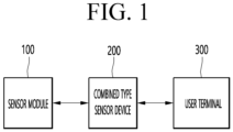
- FIG. 1 is a diagram showing a sensing system according to an embodiment of the present disclosure.
- a sensing system 10 may include a sensor module 100, a combined type sensor device 200, and a user terminal 300.
- the sensor module 100 may be a sensor module including a specialized sensor specialized for a specific product.
- a sensor module for a washing machine may include a turbidity sensor for measuring the turbidity of water of the washing machine
- a sensor module for a refrigerator may include a gas sensor for measuring gas in the refrigerator
- a sensor module for an air conditioner may include a radar sensor for determining whether a user is present.
- the combined type sensor device 200 may include sensors that are commonly applicable to products and may use a specialized sensor including the specific sensor module 100 combined therewith for a specific product.
- the combined type sensor device 200 may transmit information measured by various sensors of the sensor module 100 and the combined type sensor device 200 to the user terminal 300.
- the user terminal 300 may provide an interface that receives information measured from the combined type sensor device 200 or manages the combined type sensor device 200.
- the user terminal 300 may be implemented as a fixed device or a mobile device, such as a a desktop computer, a mobile phone, a smart phone, a notebook computer, a tablet PC, and a wearable device.
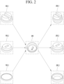
- FIG. 2 is a diagram for explaining a method of combining a sensor module and a combined type sensor device according to an embodiment of the present disclosure.
- a plurality of sensor modules 100_1, 100_2, and 100_3 may be combined type sensor devices 200_1, 200_2, and 200_3 that are combined with the combined type sensor device 200 and are to be used in a specific product, respectively.
- the combined type sensor device 200 may be a combined type sensor device 200_1 for a washing machine, which is combined with a sensor module 100_1 for a washing machine, which includes a turbidity sensor for measuring the turbidity of water.
- the combined type sensor device 200 may be a combined type sensor device 200_2 for a refrigerator, which is combined with a sensor module 100_2 for a refrigerator, including a gas sensor for measuring gas in a refrigerator.
- the combined type sensor device 200 may be a combined type sensor device 200_3 for an air conditioner, which is combined with a sensor module 100_3 for an air conditioner, including a radar sensor for determining whether a user is present.
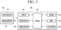
- FIG. 3 is a block diagram showing a sensor module and a combined type sensor device according to an embodiment of the present disclosure.
- the sensor module 100 may include a specific resistor part 110 and a specialized sensor part 120.
- the specific resistor part 110 may include a specific resistor having a unique resistance value for identifying a type of the sensor module 100 by the combined type sensor device 200 when the sensor module 100 is combined with the combined type sensor device 200.
- the sensor module 100_1 for a washing machine, the sensor module 100_2 for a refrigerator, and the sensor module 100_3 for an air conditioner may include specific resistors having different resistance values, respectively.
- the sensor module 100_1 for a washing machine, the sensor module 100_2 for a refrigerator, and the sensor module 100_3 for an air conditioner may include specific resistors having resistance values of 200 kQ, 300 kQ, and 100 kQ, respectively.
- the combined type sensor device 200 may identify a type of the sensor module 100 based on a resistivity value of the specific resistor part 110 of the sensor module 100.
- the specialized sensor part 120 may include a specialized sensor specialized for a specific product.
- the sensor module 100_1 for a washing machine may include a turbidity sensor for measuring the turbidity of water of a washing machine by the specialized sensor part 120.
- the turbidity sensor may be a total dissolved solids (TDS) sensor.
- the sensor module 100_2 for a refrigerator may include a gas sensor for measuring gas in the refrigerator.
- the gas sensor may measure a degree of decay of food stored in the refrigerator.
- the sensor module 100_3 for an air conditioner may include a radar sensor for determining whether a user is present. In this case, the radar sensor may include a millimeter wave (mmWave) sensor.
- mmWave millimeter wave
- the combined type sensor device 200 may include a connector 210, a fixed resistor part 220, a common sensor part 230, a transceiver 240, a memory 250, an output interface 260, and a processor 270.
- the connector 210 may include a coupling member for combination with the sensor module 100.
- the fixed resistor part 220 may include a fixed resistor having a fixed resistor value.
- the fixed resistor part 220 may include a resistor having a fixed resistance value in order to output a changed voltage depending on a resistivity value of the sensor module 100 when the sensor module 100 is combined with the combined type sensor device 200.
- the common sensor part 230 may include a sensor that is commonly applied to products.
- the common sensor part 230 may irfclude a pressure sensor, a humidity sensor, and a temperature sensor.
- the transceiver 240 may transmit and receive data with external devices such as the user terminal 300 using wired and wireless communication technology.
- communication technology used by the transceiver 2400 may include Global System for Mobile communication (GSM), Code Division Multi Access (CDMA), Long Term Evolution (LTE), 5G, Wireless LAN (WLAN), Wireless-Fidelity (Wi-Fi), Bluetooth, Bluetooth Low Energy (BLE), Radio Frequency Identification (RFID), Infrared Data Association (IrDA), ZigBee, and Near Field Communication (NFC).
- GSM Global System for Mobile communication
- CDMA Code Division Multi Access
- LTE Long Term Evolution
- 5G Fifth Generation
- WLAN Wireless LAN
- Wi-Fi Wireless-Fidelity
- Bluetooth Bluetooth Low Energy
- RFID Radio Frequency Identification
- IrDA Infrared Data Association
- ZigBee ZigBee
- NFC Near Field Communication
- the memory 250 may store data for supporting various functions of the combined type sensor device 200.
- the memory 250 may store data received from the user terminal 300.
- the output interface 260 may generate output related to visual, auditory or tactile, etc.
- the processor 270 In order to drive an application program stored in the processor 270, at least some of components of the combined type sensor device 200 may be controlled. In order to drive the application program, the processor 270 may combine and operate two or more of the components of the combined type sensor device 200.
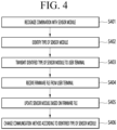
- FIG. 4 is a diagram for explaining an operating method of a combined type sensor device according to an embodiment of the present disclosure.
- the processor 270 of the combined type sensor device 270 may recognize combination of the sensor module 100 (S410).
- the sensor module 100 and the combined type sensor device 200 may be combined through the connector 210 of the combined type sensor device 270.
- FIG. 5 is a diagram for explaining a connector according to an embodiment of the present disclosure.
- the combined type sensor device 200 may include the connector 210 including a coupling member on which at least one groove is formed for combination with the sensor module 100.
- the processor 270 may identify a type of the sensor module 100 (S402).
- FIG. 6 is a diagram for explaining a method of identifying a sensor module according to an embodiment of the present disclosure.
- the sensor module 100 may include the specific resistor part 110.
- the specific resistor part 110 may have different resistance values for each type of the sensor module 100.
- a resistivity value of the specific resistor part 110 may have different values for respective types of the plurality of sensor modules 100.
- the sensor module 100_1 for a washing machine, the sensor module 100_2 for a refrigerator, and the sensor module 100_3 for an air conditioner may include specific resistors having resistance values of 200 kQ, 300 kQ, and 100 kQ, respectively.
- the sensor module 100 and the combined type sensor device 200 may be combined through the connector 210.
- the fixed resistor part 220 of the combined type sensor device 200 may be connected to the specific resistor part 110 of the sensor module 100.
- a reference voltage V ref of the sensor module 100 may have an output voltage V out shown in Table 1 in the combined type sensor device 200 depending on a resistivity value of the specific resistor part.
- the processor 270 of the combined type sensor device 200 may identify a type of the sensor module 100 coupled based on the output voltage V out when the specific resistor part 110 and the fixed resistor part 220 are connected.
- the processor 270 may transmit the identified type of the sensor module to the user terminal 300 (S403).
- the user terminal 300 may receive information on a type of the sensor module from the combined type sensor device 200 and may provide a sensor module management interface for managing the combined type sensor device 200.
- FIG. 7 is a diagram for explaining a combined type sensor module management interface according to an embodiment of the present disclosure.
- a sensor module management interface 700 may output sensor module type information 710 to a display of the user terminal 300.
- the user terminal 300 may download a firmware file related to firmware and software according to a type of a sensor module, and may transmit a firmware file suitable for the sensor module to the combined type sensor device 200.
- the processor 270 may receive a firmware file from the user terminal 300 through the transceiver 240 (S404).
- the processor 270 may update the sensor module 100 based on the firmware file (S405).
- the combined type sensor device 200 may maintain an up-to-data firmware update state.
- the processor 270 may change communication setting according to the identified type of the sensor module (S460).
- the combined type sensor device 200 when the combined type sensor device 200 is combined with the sensor module 100_1 for a washing machine, the combined type sensor device 200 may detect turbidity in the washing machine. In this case, when the washing machine uses a lot of water and there is a lot of laundry, there may be a problem that Bluetooth Low Energy (BLE) is cut off. Thus, communication setting needs to be changed depending on a type of the sensor module 100.
- BLE Bluetooth Low Energy
- communication setting for the case in which a first sensor module specialized for a product that causes a communication problem due to water using a large amount of water, such as the sensor module 100_1 for a washing machine, is coupled to the combined type sensor device 200 and communication setting for the case in which a second sensor module specialized for a product with a less communication problem caused by water, such as the sensor module 100_2 for a refrigerator or the sensor module 100_3 for an air conditioner, is coupled to the combined type sensor device 200 may be differently set.
- the processor 270 may change Bluetooth Low Energy (BLE) communication setting provided by the transceiver 240 according the first sensor module or the second sensor module.
- BLE Bluetooth Low Energy
- FIG. 8 is a flowchart for explaining a communication setting method in the case of combination of a first sensor module according to an embodiment of the present disclosure.
- the processor 270 may identify a coupled sensor module and may perform first communication setting when the identified type of the sensor module is a first sensor module.
- the first sensor module may include the sensor module 100_1 for a washing ma5chine.
- the processor 270 may change Bluetooth Low Energy (BLE) communication setting provided by the transceiver 240 according to the first sensor module.
- BLE Bluetooth Low Energy
- the processor 270 may set Bluetooth Low Energy (BLE) Tx power to a maximum value (S801).
- the maximum value of Bluetooth Low Energy (BLE) Tx power may be differently set for each country, but may be set to 8 dbm to 10 dbm.
- the processor 270 may activate an antenna switching operation (S802).
- the transceiver 240 may include a plurality of antennas for Bluetooth Low Energy (BLE) communication and may include a switch for switching to each of the plurality of antennas.
- the plurality of antennas may have directionality for receiving communication signals in different directions, respectively.
- the processor 270 may activate the antenna switching operation and controls switching to another second antenna whenever a disconnection phenomenon occurs in a communication signal received through a first antenna among the plurality of antennas.
- the processor 270 may set a Coded PHY mode.
- the processor 270 may set mode setting of Bluetooth communication used by the transceiver 240.
- the Coded PHY mode may be a protocol added to Blue 5.0 and to improve RX sensitivity and to increase reach.
- the Coded PHY mode may apply Forward Error Correction (FEC) to a packet to correct a bit error at a receiving side and to lower a bit error rate and may apply a pattern mapper to the packet to improve communication efficiency.
- FEC Forward Error Correction
- the processor 270 may activate a batching mode (S804).
- the processor 270 may set mode setting of Bluetooth communication used by the transceiver 240 to the batching mode.
- the processor 270 may activate the batching mode and may store sensing information generated by the sensor module or the combined type sensor device in a buffer.
- the processor 270 may activate the batching mode and may store first sensing information generated by the specialized sensor part 120 of the sensor module 100 and second sensing information generated by the common sensor part 230 of a combined type fixed device 200, in the buffer.
- the processor 270 may re-transmit the sensing information stored in the buffer to the user terminal 300 through the transceiver 240 when communication with the user terminal 300 is connected again after disconnection.
- the processor 270 may activate an auto connection mode (S805).
- the first sensor module is a sensor module specialized for a product having a problem in communication
- a communication disconnect phenomenon may occur, and thus when frequency sensitivity of the transceiver 240 and the user terminal 300 is greater than or equal to a predetermined value, the processor 270 may activate the auto connection mode in which the transceiver 240 automatically performs communication connection wi5th the user terminal 300.
- communication connection may be established.
- FIG. 9 is a flowchart for explaining a communication setting method in the case of combination of a second sensor module according to an embodiment of the present disclosure.
- the processor 270 may identify a coupled sensor module and may perform second communication setting when the identified type of the sensor module is a second sensor module.
- the first sensor module may include the sensor module 100_2 for a refrigerator or the sensor module 100_3 for an air conditioner.
- the processor 270 may change Bluetooth Low Energy (BLE) communication setting provided from the transceiver 240 according to the second sensor module.
- BLE Bluetooth Low Energy
- the processor 270 may set Bluetooth Low Energy (BLE) Tx power to a minimum value (S901).
- BLE Bluetooth Low Energy
- S901 the minimum value of the Bluetooth Low Energy (BLE) Tx power may be set to 0 dbm.
- the processor 270 may deactivate the antenna switching operation (S902).
- the combined type sensor device 200 may be fixed during an operation of a product, and thus the antenna switching operation may not be required.
- the processor 270 may set a 1M PHY mode (S903).
- a data transfer rate in the PHY may be fixed to 1 Mbps.
- the processor 270 may deactivate the batching mode (S904).
- the processor 270 may deactivate the batching mode and may continuously transmit the first sensing information generated by the specialized sensor part 120 of the sensor module 100 and the second sensing information generated by the common sensor part 230 of the combined type fixed device 200 to the user terminal 300 through the transceiver 240.
- the processor 270 may deactivate the auto connection mode (S905).
- the second sensor module is a sensor module specialized for a product with a less communication problem, communication disconnection occurs less frequently, and thus the processor 270 may deactivate the auto connection mode to reduce battery power consumption.
- the combined type sensor device 5 display device may be combined with sensor modules specialized for various home appliances in use as necessary, thus achieving remarkable industrial applicability.
Landscapes
- Engineering & Computer Science (AREA)
- Computer Networks & Wireless Communication (AREA)
- Software Systems (AREA)
- Theoretical Computer Science (AREA)
- Signal Processing (AREA)
- Physics & Mathematics (AREA)
- General Physics & Mathematics (AREA)
- General Engineering & Computer Science (AREA)
- Computer Security & Cryptography (AREA)
- Automation & Control Theory (AREA)
- Textile Engineering (AREA)
- Selective Calling Equipment (AREA)
Abstract
Description
- The present disclosure relates to a combined type sensor device combined with a sensor module, and more particularly to a combined type sensor device for sensing by being combined with each of a plurality of sensor modules including a sensor for a specific device.
- Recently, due to the continued smartization of home appliances, new sensors have been added to newly released products. In addition, as new sensors are added, new functions have been added to home appliances.
- However, home appliances that have already been released have a problem in that new sensors need to be added as hardware. In order to replace with a new sensor, there is a problem in that a new sensor needs to be added and reassembled after disassembling the home appliance.
- Therefore, there is a need for a technology for combining and using a new sensor without disassembling the product.
- An object of an embodiment of the present disclosure is to provide a combined type sensor device combined with sensor modules specialized for various home appliances in use as necessary.
- An object of an embodiment of the present disclosure is tc5 provide a combined type sensor device for updating firmware by automatically recognizing a type of the combined sensor module.
- An object of an embodiment of the present disclosure is to provide a combined type sensor device for solving a communication disconnection problem according to a product use environment by differently setting communication setting depending on a type of a combined sensor module.
- An embodiment provides a combined type sensor device including a transceiver configured to transmit and receive data to and from a user terminal, a connector combined with a sensor module, and a processor configured to identify a type of the sensor module, to transmit the identified type of the sensor module to the user terminal through the transceiver, to update the sensor module based on a firmware file received from the user terminal through the transceiver, and to change communication setting according to the identified type of the sensor module.
- The connector may include a coupling member including at least one groove formed thereon.
- The sensor module may include a specific resistor part having a different resistivity value for each type of the sensor module, the combined type sensor device may further include a fixed resistor part having a predetermined fixed resistance value, and the processor may identify the type of the sensor module based on an output voltage when the specific resistor part and the fixed resistor part are connected.
- The sensor module may further include a specialized sensor part including a specialized sensor specialized for a specific product.
- When the sensor module is a sensor module for a washing machine, the specialized sensor part may include a turbidity sensor.
- The combined type sensor device may further include a common sensor part including a sensor that is commonly applied to a product.
- When the type of the sensor module is a first sensor module, the processor may set Bluetooth Low Energy (BLE) Tx power tt6 a maximum value.
- The transceiver may include a plurality of antennas having directionality for receiving communication signals in different directions for Bluetooth Low Energy (BLE) communication and a switch for switching to each of the plurality of antennas, and the processor may activate an antenna switching operation and controls the switch to control switching to another second antenna whenever a disconnection phenomenon occurs in a communication signal received through a first antenna among the plurality of antennas.
- The processor may set mode setting of Bluetooth communication used by the transceiver to a Coded PHY mode.
- The processor may store sensing information generated by the combined type sensor device in a buffer and activates a batching mode of re-transmitting the sensing information stored in the buffer to the user terminal through the transceiver when communication with the user terminal is connected again after disconnection.
- When frequency sensitivity of the transceiver and the user terminal is greater than or equal to a predetermined value, the processor may activate an auto connection mode in which the transceiver performs communication connection with the user terminal.
- When the type of the sensor module is a second sensor module, the processor may set Bluetooth Low Energy (BLE) Tx power to a minimum value.
- The processor may deactivate an antenna switching operation, may set mode setting of Bluetooth communication used by the transceiver to a 1M PHY mode, may deactivate a batching mode, and may deactivate an auto connection mode.
- A combined type sensor device according to an embodiment of the present disclosure may be combined with sensor modules specialized for various home appliances in use as necessary.
- The combined type sensor device according to an embodiment of the present disclosure may update firmware by automatically recognizing a type of the combined sensor module.
- The combined type sensor device according to an embodiment of the present disclosure may solve a communication disconnection problem according to a product use environment by differently setting communication setting depending on a type of a combined sensor module.
-
-
FIG. 1 is a diagram showing a sensing system according to an embodiment of the present disclosure. -
FIG. 2 is a diagram for explaining a method of combining a10sensor module and a combined type sensor device according to an embodiment of the present disclosure. -
FIG. 3 is a block diagram showing a sensor module and a combined type sensor device according to an embodiment of the present disclosure. -
FIG. 4 is a diagram for explaining an operating method of a combined type sensor device according to an embodiment of the present disclosure. -
FIG. 5 is a diagram for explaining a connector according to an embodiment of the present disclosure. -
FIG. 6 is a diagram for explaining a method of identifying a sensor module according to an embodiment of the present disclosure. -
FIG. 7 is a diagram for explaining a combined type sensor module management interface according to an embodiment of the present disclosure. -
FIG. 8 is a flowchart for explaining a communication setting method in the case of combination of a first sensor module according to an embodiment of the present disclosure. -
FIG. 9 is a flowchart for explaining a communication setting method in the case of combination of a second sensor module according to an embodiment of the present disclosure. - Hereinafter, embodiments of the present disclosure will be described in further detail with reference to the accompanying drawings. In the following description, the terms "module" and "unit", which are used herein to signify components, are merely intended to facilitate explanation of the present disclosure, and the terms do not have any distinguishable difference in meaning or role.
-
FIG. 1 is a diagram showing a sensing system according to an embodiment of the present disclosure. - Referring to
FIG. 1 , asensing system 10 may include asensor module 100, a combinedtype sensor device 200, and auser terminal 300. - The
sensor module 100 may be a sensor module including a specialized sensor specialized for a specific product. For example, a sensor module for a washing machine may include a turbidity sensor for measuring the turbidity of water of the washing machine, a sensor module for a refrigerator may include a gas sensor for measuring gas in the refrigerator, and a sensor module for an air conditioner may include a radar sensor for determining whether a user is present. - The combined
type sensor device 200 may include sensors that are commonly applicable to products and may use a specialized sensor including thespecific sensor module 100 combined therewith for a specific product. - The combined
type sensor device 200 may transmit information measured by various sensors of thesensor module 100 and the combinedtype sensor device 200 to theuser terminal 300. - The
user terminal 300 may provide an interface that receives information measured from the combinedtype sensor device 200 or manages the combinedtype sensor device 200. Theuser terminal 300 may be implemented as a fixed device or a mobile device, such as a a desktop computer, a mobile phone, a smart phone, a notebook computer, a tablet PC, and a wearable device. -
FIG. 2 is a diagram for explaining a method of combining a sensor module and a combined type sensor device according to an embodiment of the present disclosure. - Referring to
FIG. 2 , a plurality of sensor modules 100_1, 100_2, and 100_3 may be combined type sensor devices 200_1, 200_2, and 200_3 that are combined with the combinedtype sensor device 200 and are to be used in a specific product, respectively. - For example, the combined
type sensor device 200 may be a combined type sensor device 200_1 for a washing machine, which is combined with a sensor module 100_1 for a washing machine, which includes a turbidity sensor for measuring the turbidity of water. The combinedtype sensor device 200 may be a combined type sensor device 200_2 for a refrigerator, which is combined with a sensor module 100_2 for a refrigerator, including a gas sensor for measuring gas in a refrigerator. The combinedtype sensor device 200 may be a combined type sensor device 200_3 for an air conditioner, which is combined with a sensor module 100_3 for an air conditioner, including a radar sensor for determining whether a user is present. -
FIG. 3 is a block diagram showing a sensor module and a combined type sensor device according to an embodiment of the present disclosure. - Referring to
FIG. 3 , thesensor module 100 may include aspecific resistor part 110 and aspecialized sensor part 120. - The
specific resistor part 110 may include a specific resistor having a unique resistance value for identifying a type of thesensor module 100 by the combinedtype sensor device 200 when thesensor module 100 is combined with the combinedtype sensor device 200. - For example, the sensor module 100_1 for a washing machine, the sensor module 100_2 for a refrigerator, and the sensor module 100_3 for an air conditioner may include specific resistors having different resistance values, respectively. The sensor module 100_1 for a washing machine, the sensor module 100_2 for a refrigerator, and the sensor module 100_3 for an air conditioner may include specific resistors having resistance values of 200 kQ, 300 kQ, and 100 kQ, respectively. The combined
type sensor device 200 may identify a type of thesensor module 100 based on a resistivity value of thespecific resistor part 110 of thesensor module 100. - The
specialized sensor part 120 may include a specialized sensor specialized for a specific product. For example, the sensor module 100_1 for a washing machine may include a turbidity sensor for measuring the turbidity of water of a washing machine by thespecialized sensor part 120. In this case, the turbidity sensor may be a total dissolved solids (TDS) sensor. The sensor module 100_2 for a refrigerator may include a gas sensor for measuring gas in the refrigerator. The gas sensor may measure a degree of decay of food stored in the refrigerator. The sensor module 100_3 for an air conditioner may include a radar sensor for determining whether a user is present. In this case, the radar sensor may include a millimeter wave (mmWave) sensor. - The combined
type sensor device 200 may include aconnector 210, a fixedresistor part 220, acommon sensor part 230, atransceiver 240, amemory 250, anoutput interface 260, and aprocessor 270. - The
connector 210 may include a coupling member for combination with thesensor module 100. - The fixed
resistor part 220 may include a fixed resistor having a fixed resistor value. The fixedresistor part 220 may include a resistor having a fixed resistance value in order to output a changed voltage depending on a resistivity value of thesensor module 100 when thesensor module 100 is combined with the combinedtype sensor device 200. - The
common sensor part 230 may include a sensor that is commonly applied to products. Thecommon sensor part 230 may irfclude a pressure sensor, a humidity sensor, and a temperature sensor. - The
transceiver 240 may transmit and receive data with external devices such as theuser terminal 300 using wired and wireless communication technology. In this case, communication technology used by the transceiver 2400 may include Global System for Mobile communication (GSM), Code Division Multi Access (CDMA), Long Term Evolution (LTE), 5G, Wireless LAN (WLAN), Wireless-Fidelity (Wi-Fi), Bluetooth, Bluetooth Low Energy (BLE), Radio Frequency Identification (RFID), Infrared Data Association (IrDA), ZigBee, and Near Field Communication (NFC). - The
memory 250 may store data for supporting various functions of the combinedtype sensor device 200. For example, thememory 250 may store data received from theuser terminal 300. - The
output interface 260 may generate output related to visual, auditory or tactile, etc. - In order to drive an application program stored in the
processor 270, at least some of components of the combinedtype sensor device 200 may be controlled. In order to drive the application program, theprocessor 270 may combine and operate two or more of the components of the combinedtype sensor device 200. -
FIG. 4 is a diagram for explaining an operating method of a combined type sensor device according to an embodiment of the present disclosure. - The
processor 270 of the combinedtype sensor device 270 may recognize combination of the sensor module 100 (S410). - For example, the
sensor module 100 and the combinedtype sensor device 200 may be combined through theconnector 210 of the combinedtype sensor device 270. -
FIG. 5 is a diagram for explaining a connector according to an embodiment of the present disclosure. - Referring to
FIG. 5 , the combinedtype sensor device 200 may include theconnector 210 including a coupling member on which at least one groove is formed for combination with thesensor module 100. - The
processor 270 may identify a type of the sensor module 100 (S402). -
FIG. 6 is a diagram for explaining a method of identifying a sensor module according to an embodiment of the present disclosure. - Referring to
FIG. 6 , thesensor module 100 may include thespecific resistor part 110. Thespecific resistor part 110 may have different resistance values for each type of thesensor module 100. - A resistivity value of the
specific resistor part 110 may have different values for respective types of the plurality ofsensor modules 100. For example, the sensor module 100_1 for a washing machine, the sensor module 100_2 for a refrigerator, and the sensor module 100_3 for an air conditioner may include specific resistors having resistance values of 200 kQ, 300 kQ, and 100 kQ, respectively. - The
sensor module 100 and the combinedtype sensor device 200 may be combined through theconnector 210. - The fixed
resistor part 220 of the combinedtype sensor device 200 may be connected to thespecific resistor part 110 of thesensor module 100. - When the
specific resistor part 110 and the fixedresistor part 220 are connected to each other, a reference voltage Vref of thesensor module 100 may have an output voltage Vout shown in Table 1 in the combinedtype sensor device 200 depending on a resistivity value of the specific resistor part. -
[Table 1] Type of Sensor Module Resistivity Value Output Voltage Vout Sensor Module for Air Conditioner 100 kΩ 1/3* Vref Sensor module for Washing Machine 200 kΩ 2/3* Vref Sensor Module for Refrigerator 300 kΩ 3/3* Vref - The
processor 270 of the combinedtype sensor device 200 may identify a type of thesensor module 100 coupled based on the output voltage Vout when thespecific resistor part 110 and the fixedresistor part 220 are connected. - The
processor 270 may transmit the identified type of the sensor module to the user terminal 300 (S403). - The
user terminal 300 may receive information on a type of the sensor module from the combinedtype sensor device 200 and may provide a sensor module management interface for managing the combinedtype sensor device 200. -
FIG. 7 is a diagram for explaining a combined type sensor module management interface according to an embodiment of the present disclosure. - Referring to
FIG. 7 , a sensormodule management interface 700 may output sensor module type information 710 to a display of theuser terminal 300. - The
user terminal 300 may download a firmware file related to firmware and software according to a type of a sensor module, and may transmit a firmware file suitable for the sensor module to the combinedtype sensor device 200. - Referring back to
FIG. 4 , theprocessor 270 may receive a firmware file from theuser terminal 300 through the transceiver 240 (S404). - The
processor 270 may update thesensor module 100 based on the firmware file (S405). - Thus, the combined
type sensor device 200 may maintain an up-to-data firmware update state. - The
processor 270 may change communication setting according to the identified type of the sensor module (S460). - For example, when the combined
type sensor device 200 is combined with the sensor module 100_1 for a washing machine, the combinedtype sensor device 200 may detect turbidity in the washing machine. In this case, when the washing machine uses a lot of water and there is a lot of laundry, there may be a problem that Bluetooth Low Energy (BLE) is cut off. Thus, communication setting needs to be changed depending on a type of thesensor module 100. For example, communication setting for the case in which a first sensor module specialized for a product that causes a communication problem due to water using a large amount of water, such as the sensor module 100_1 for a washing machine, is coupled to the combinedtype sensor device 200 and communication setting for the case in which a second sensor module specialized for a product with a less communication problem caused by water, such as the sensor module 100_2 for a refrigerator or the sensor module 100_3 for an air conditioner, is coupled to the combinedtype sensor device 200 may be differently set. - The
processor 270 may change Bluetooth Low Energy (BLE) communication setting provided by thetransceiver 240 according the first sensor module or the second sensor module. -
FIG. 8 is a flowchart for explaining a communication setting method in the case of combination of a first sensor module according to an embodiment of the present disclosure. - The
processor 270 may identify a coupled sensor module and may perform first communication setting when the identified type of the sensor module is a first sensor module. The first sensor module may include the sensor module 100_1 for a washing ma5chine. - The
processor 270 may change Bluetooth Low Energy (BLE) communication setting provided by thetransceiver 240 according to the first sensor module. - The
processor 270 may set Bluetooth Low Energy (BLE) Tx power to a maximum value (S801). The maximum value of Bluetooth Low Energy (BLE) Tx power may be differently set for each country, but may be set to 8 dbm to 10 dbm. - The
processor 270 may activate an antenna switching operation (S802). - For example, the
transceiver 240 may include a plurality of antennas for Bluetooth Low Energy (BLE) communication and may include a switch for switching to each of the plurality of antennas. The plurality of antennas may have directionality for receiving communication signals in different directions, respectively. - The
processor 270 may activate the antenna switching operation and controls switching to another second antenna whenever a disconnection phenomenon occurs in a communication signal received through a first antenna among the plurality of antennas. - The
processor 270 may set a Coded PHY mode. - The
processor 270 may set mode setting of Bluetooth communication used by thetransceiver 240. - The Coded PHY mode may be a protocol added to Blue 5.0 and to improve RX sensitivity and to increase reach.
- The Coded PHY mode may apply Forward Error Correction (FEC) to a packet to correct a bit error at a receiving side and to lower a bit error rate and may apply a pattern mapper to the packet to improve communication efficiency.
- The
processor 270 may activate a batching mode (S804). - The
processor 270 may set mode setting of Bluetooth communication used by thetransceiver 240 to the batching mode. - The
processor 270 may activate the batching mode and may store sensing information generated by the sensor module or the combined type sensor device in a buffer. - The
processor 270 may activate the batching mode and may store first sensing information generated by thespecialized sensor part 120 of thesensor module 100 and second sensing information generated by thecommon sensor part 230 of a combined type fixeddevice 200, in the buffer. - The
processor 270 may re-transmit the sensing information stored in the buffer to theuser terminal 300 through thetransceiver 240 when communication with theuser terminal 300 is connected again after disconnection. - The
processor 270 may activate an auto connection mode (S805). - Since the first sensor module is a sensor module specialized for a product having a problem in communication, a communication disconnect phenomenon may occur, and thus when frequency sensitivity of the
transceiver 240 and theuser terminal 300 is greater than or equal to a predetermined value, theprocessor 270 may activate the auto connection mode in which thetransceiver 240 automatically performs communication connection wi5th theuser terminal 300. Thus, even if communication is cut off, if sensitivity for enabling communication connection again is received, communication connection may be established. -
FIG. 9 is a flowchart for explaining a communication setting method in the case of combination of a second sensor module according to an embodiment of the present disclosure. - The
processor 270 may identify a coupled sensor module and may perform second communication setting when the identified type of the sensor module is a second sensor module. The first sensor module may include the sensor module 100_2 for a refrigerator or the sensor module 100_3 for an air conditioner. - The
processor 270 may change Bluetooth Low Energy (BLE) communication setting provided from thetransceiver 240 according to the second sensor module. - The
processor 270 may set Bluetooth Low Energy (BLE) Tx power to a minimum value (S901). For example, the minimum value of the Bluetooth Low Energy (BLE) Tx power may be set to 0 dbm. - The
processor 270 may deactivate the antenna switching operation (S902). - When the second sensor module is the sensor module 100_2 for a refrigerator or the sensor module 100_3 for an air conditioner, the combined
type sensor device 200 may be fixed during an operation of a product, and thus the antenna switching operation may not be required. - The
processor 270 may set a 1M PHY mode (S903). - In the 1M PHY mode, a data transfer rate in the PHY may be fixed to 1 Mbps.
- The
processor 270 may deactivate the batching mode (S904). - The
processor 270 may deactivate the batching mode and may continuously transmit the first sensing information generated by thespecialized sensor part 120 of thesensor module 100 and the second sensing information generated by thecommon sensor part 230 of the combined type fixeddevice 200 to theuser terminal 300 through thetransceiver 240. - The
processor 270 may deactivate the auto connection mode (S905). - Since the second sensor module is a sensor module specialized for a product with a less communication problem, communication disconnection occurs less frequently, and thus the
processor 270 may deactivate the auto connection mode to reduce battery power consumption. - Accordingly, the embodiments disclosed in the present disclosure are not intended to limit the technical ideas of the present disclosure, but to explain, and the scope of the technical spirit of the present disclosure is not limited by these embodiments.
- The scope of the present disclosure should be construed by the following claims, and all technical ideas within the scope equivalent thereto should be construed as being included in the scope of the present disclosure.
- According to the combined type sensor device 5 display device according to the present disclosure, it may be combined with sensor modules specialized for various home appliances in use as necessary, thus achieving remarkable industrial applicability.
Claims (13)
- A combined type sensor device comprising:a transceiver configured to transmit and receive data to and from a user terminal;a connector combined with a sensor module; anda processor configured to identify a type of the sensor module, to transmit the identified type of the sensor module to the user terminal through the transceiver, to update the sensor module based on a firmware file received from the user terminal through the transceiver, and to change communication setting according to the identified type of the sensor module.
- The combined type sensor device of claim 1, wherein the connector includes a coupling member including at least one groove formed thereon.
- The combined type sensor device of claim 1, wherein:the sensor module includes a specific resistor part having a different resistivity value for each type of the sensor module;the combined type sensor device further includes a fixed resistor part having a predetermined fixed resistance value; andthe processor identifies the type of the sensor module based on an output voltage when the specific resistor part and the fixed resistor part are connected.
- The combined type sensor device of claim 3, wherein the sensor module further includes a specialized sensor part including a specialized sensor specialized for a specific product.
- The combined type sensor device of claim 4, wherein, when the sensor module is a sensor module for a washing machine, the specialized sensor part includes a turbidity sensor.
- The combined type sensor device of claim 4, wherein the combined type sensor device further includes a common sensor part including a sensor that is commonly applied to a product.
- The combined type sensor device of claim 1, wherein, when the type of the sensor module is a first sensor module, the processor sets Bluetooth Low Energy (BLE) Tx power to a maximum value.
- The combined type sensor device of claim 7, wherein:the transceiver includes a plurality of antennas having directionality for receiving communication signals in different directions for Bluetooth Low Energy (BLE) communication and a switch for switching to each of the plurality of antennas; andthe processor activates an antenna switching operation and controls the switch to control switching to another second antenna whenever a disconnection phenomenon occurs in a communication signal received through a first antenna among the plurality of antennas.
- The combined type sensor device of claim 8, wherein the processor sets mode setting of Bluetooth communication used by the transceiver to a Coded PHY mode.
- The combined type sensor device of claim 9, wherein the processor stores sensing information generated by the combined type sensor device in a buffer and activates a batching mode of re-transmitting the sensing information stored in the buffer to the user terminal through the transceiver when communication with the user terminal is connected again after disconnection.
- The combined type sensor device of claim 10, wherein, when frequency sensitivity of the transceiver and the user terminal is greater than or equal to a predetermined value, the processor activates an auto connection mode in which the transceiver performs communication connection with the user terminal.
- The combined type sensor device of claim 1, wherein, when the type of the sensor module is a second sensor module, the processor sets Bluetooth Low Energy (BLE) Tx power to a minimum value.
- The combined type sensor device of claim 12, wherein the processor deactivates an antenna switching operation, sets mode setting of Bluetooth communication used by the transceiver to a 1M PHY mode, deactivates a batching mode, and deactivates an auto connection mode.
Applications Claiming Priority (2)
| Application Number | Priority Date | Filing Date | Title |
|---|---|---|---|
| KR1020220046048A KR102794630B1 (en) | 2022-04-14 | 2022-04-14 | Edge computing device and method for external software interworking |
| PCT/KR2022/007126 WO2023200040A1 (en) | 2022-04-14 | 2022-05-18 | Combination-type sensor device in which sensor module is combined |
Publications (2)
| Publication Number | Publication Date |
|---|---|
| EP4492014A1 true EP4492014A1 (en) | 2025-01-15 |
| EP4492014A4 EP4492014A4 (en) | 2025-06-25 |
Family
ID=88308657
Family Applications (1)
| Application Number | Title | Priority Date | Filing Date |
|---|---|---|---|
| EP22937553.0A Pending EP4492014A4 (en) | 2022-04-14 | 2022-05-18 | COMBINED SENSOR DEVICE WITH A COMBINED SENSOR MODULE |
Country Status (4)
| Country | Link |
|---|---|
| US (1) | US20230329516A1 (en) |
| EP (1) | EP4492014A4 (en) |
| KR (1) | KR102794630B1 (en) |
| WO (1) | WO2023200040A1 (en) |
Families Citing this family (1)
| Publication number | Priority date | Publication date | Assignee | Title |
|---|---|---|---|---|
| CN120252835B (en) * | 2025-03-31 | 2025-09-23 | 广州天之骄子电子科技股份有限公司 | A multifunctional combined sensor |
Family Cites Families (17)
| Publication number | Priority date | Publication date | Assignee | Title |
|---|---|---|---|---|
| AU4669397A (en) * | 1996-10-04 | 1998-04-24 | Fisher Controls International Inc. | Process control network with redundant field devices and busses |
| JP3553050B2 (en) * | 2002-05-28 | 2004-08-11 | 株式会社エイティング | Videophone monitoring system |
| TW200416552A (en) * | 2002-12-09 | 2004-09-01 | Kokuyo Kk | Information processing device, control device, containing tool guarding device and program. |
| JP2005050005A (en) * | 2003-07-31 | 2005-02-24 | Hitachi Ltd | Information providing method, information providing terminal and vehicle |
| US20060129347A1 (en) * | 2004-12-10 | 2006-06-15 | The Regents Of The University Of Californica | Generic transducer interface |
| US20100120466A1 (en) * | 2008-11-12 | 2010-05-13 | Nokia Corporation | Multi-mode antenna switching |
| US8928339B2 (en) * | 2010-10-29 | 2015-01-06 | The Boeing Company | Methods and systems for automated measurement of electrical bonds |
| KR20130062867A (en) * | 2011-12-05 | 2013-06-13 | 주식회사 이노튜브 | Data converter for recognizing sensing |
| JP2014112819A (en) * | 2012-10-30 | 2014-06-19 | Yokogawa Electric Corp | Radio equipment, input/output unit, radio unit and radio equipment setup method |
| DE102013111714B8 (en) * | 2013-10-24 | 2024-10-02 | Endress+Hauser Conducta Gmbh+Co. Kg | Procedure for setting the function of a measuring point |
| KR102554759B1 (en) * | 2016-02-19 | 2023-07-12 | 삼성전자주식회사 | Antenna and electronic device having it |
| KR101794290B1 (en) * | 2016-03-04 | 2017-11-06 | 노건욱 | Beacon transmission apparatus and beacon transmission method |
| WO2019156681A1 (en) * | 2018-02-09 | 2019-08-15 | NanoThings, Inc. | Item status tracking system and method |
| KR101788474B1 (en) * | 2016-11-30 | 2017-10-19 | 울산대학교 산학협력단 | Compound Sensor Communication Device and method for identifying sensor module thereof |
| KR101757417B1 (en) * | 2017-04-19 | 2017-07-12 | 주식회사 주빅스 | Method for updating communication node firmware in wireless communication |
| DE102018131701A1 (en) * | 2018-12-11 | 2020-06-18 | Endress+Hauser Conducta Gmbh+Co. Kg | Method for parameterizing a field device |
| WO2020147924A1 (en) * | 2019-01-15 | 2020-07-23 | Telefonaktiebolaget Lm Ericsson (Publ) | Providing communication services using sets of i/o devices |
-
2022
- 2022-04-14 KR KR1020220046048A patent/KR102794630B1/en active Active
- 2022-05-18 EP EP22937553.0A patent/EP4492014A4/en active Pending
- 2022-05-18 WO PCT/KR2022/007126 patent/WO2023200040A1/en not_active Ceased
- 2022-08-04 US US17/881,269 patent/US20230329516A1/en active Pending
Also Published As
| Publication number | Publication date |
|---|---|
| EP4492014A4 (en) | 2025-06-25 |
| KR102794630B1 (en) | 2025-04-15 |
| KR20230147267A (en) | 2023-10-23 |
| WO2023200040A1 (en) | 2023-10-19 |
| US20230329516A1 (en) | 2023-10-19 |
Similar Documents
| Publication | Publication Date | Title |
|---|---|---|
| EP3912414B1 (en) | Apparatus and method of determining a transmission configuration indication | |
| US9892634B2 (en) | Remote control docking station and system | |
| CN108632838A (en) | A kind of measurement report method, terminal and the network side equipment of wave beam | |
| US8271032B2 (en) | Apparatus and method for managing power consumption in a mobile communication device | |
| US20190394664A1 (en) | Beam management information configuration and processing method, terminal and base station | |
| US9319981B2 (en) | Apparatus, system and method of controlling a wireless docking device | |
| EP3136773B1 (en) | Method for establishing correspondence between sector of base station and antenna, base station, and antenna | |
| US20180115858A1 (en) | Systems and methods for connecting wireless communication devices | |
| US20250039727A1 (en) | Communication method and communications apparatus | |
| EP4492014A1 (en) | Combination-type sensor device in which sensor module is combined | |
| TWM463943U (en) | Wireless communication device | |
| EP3293886B1 (en) | Radio frequency finding method, chip and device | |
| CN106877832A (en) | Antenna load matching process and device, communication terminal | |
| US12323353B2 (en) | Method for controlling radio frequency front-end device and user equipment | |
| WO2022204874A1 (en) | Power consumption control method, and wireless local area network communication apparatus | |
| CN114337948A (en) | Reference signal configuration method, antenna switching method, device and storage medium | |
| US20170171914A9 (en) | Portable wireless signal transfer system, method and terminal | |
| CN118830218A (en) | Method, terminal and network device for configuring resources | |
| CA3074337A1 (en) | Method and apparatus for determining frequency hopping of channel, and computer storage medium | |
| WO2015106422A1 (en) | Method and apparatus for adjusting peak power capability | |
| US11699926B2 (en) | Smart hub | |
| CN212788889U (en) | Paper diaper alarm system | |
| WO2024067443A1 (en) | Indication method, first device, and second device | |
| EP3383129B1 (en) | Master-slave type network-based method and apparatus for selecting management frame antenna | |
| US11223392B2 (en) | Radio module configurations for antennas |
Legal Events
| Date | Code | Title | Description |
|---|---|---|---|
| STAA | Information on the status of an ep patent application or granted ep patent |
Free format text: STATUS: THE INTERNATIONAL PUBLICATION HAS BEEN MADE |
|
| PUAI | Public reference made under article 153(3) epc to a published international application that has entered the european phase |
Free format text: ORIGINAL CODE: 0009012 |
|
| STAA | Information on the status of an ep patent application or granted ep patent |
Free format text: STATUS: REQUEST FOR EXAMINATION WAS MADE |
|
| 17P | Request for examination filed |
Effective date: 20241010 |
|
| AK | Designated contracting states |
Kind code of ref document: A1 Designated state(s): AL AT BE BG CH CY CZ DE DK EE ES FI FR GB GR HR HU IE IS IT LI LT LU LV MC MK MT NL NO PL PT RO RS SE SI SK SM TR |
|
| REG | Reference to a national code |
Ref country code: DE Ref legal event code: R079 Free format text: PREVIOUS MAIN CLASS: G01D0021020000 Ipc: G01D0021000000 |
|
| A4 | Supplementary search report drawn up and despatched |
Effective date: 20250522 |
|
| RIC1 | Information provided on ipc code assigned before grant |
Ipc: G06F 9/4401 20180101ALI20250516BHEP Ipc: G06F 8/65 20180101ALI20250516BHEP Ipc: H04W 4/80 20180101ALI20250516BHEP Ipc: H04L 12/28 20060101ALI20250516BHEP Ipc: H04L 67/00 20220101ALI20250516BHEP Ipc: H04L 67/2869 20220101ALI20250516BHEP Ipc: G01D 21/00 20060101AFI20250516BHEP |
|
| DAV | Request for validation of the european patent (deleted) | ||
| DAX | Request for extension of the european patent (deleted) | ||
| GRAP | Despatch of communication of intention to grant a patent |
Free format text: ORIGINAL CODE: EPIDOSNIGR1 |
|
| STAA | Information on the status of an ep patent application or granted ep patent |
Free format text: STATUS: GRANT OF PATENT IS INTENDED |