EP4491940A1 - Vehicle lamp - Google Patents
Vehicle lamp Download PDFInfo
- Publication number
- EP4491940A1 EP4491940A1 EP23766699.5A EP23766699A EP4491940A1 EP 4491940 A1 EP4491940 A1 EP 4491940A1 EP 23766699 A EP23766699 A EP 23766699A EP 4491940 A1 EP4491940 A1 EP 4491940A1
- Authority
- EP
- European Patent Office
- Prior art keywords
- light
- guide body
- light guide
- surface side
- vehicle lamp
- Prior art date
- Legal status (The legal status is an assumption and is not a legal conclusion. Google has not performed a legal analysis and makes no representation as to the accuracy of the status listed.)
- Pending
Links
Images




Classifications
-
- F—MECHANICAL ENGINEERING; LIGHTING; HEATING; WEAPONS; BLASTING
- F21—LIGHTING
- F21S—NON-PORTABLE LIGHTING DEVICES; SYSTEMS THEREOF; VEHICLE LIGHTING DEVICES SPECIALLY ADAPTED FOR VEHICLE EXTERIORS
- F21S43/00—Signalling devices specially adapted for vehicle exteriors, e.g. brake lamps, direction indicator lights or reversing lights
- F21S43/20—Signalling devices specially adapted for vehicle exteriors, e.g. brake lamps, direction indicator lights or reversing lights characterised by refractors, transparent cover plates, light guides or filters
- F21S43/235—Light guides
- F21S43/242—Light guides characterised by the emission area
- F21S43/245—Light guides characterised by the emission area emitting light from one or more of its major surfaces
-
- F—MECHANICAL ENGINEERING; LIGHTING; HEATING; WEAPONS; BLASTING
- F21—LIGHTING
- F21S—NON-PORTABLE LIGHTING DEVICES; SYSTEMS THEREOF; VEHICLE LIGHTING DEVICES SPECIALLY ADAPTED FOR VEHICLE EXTERIORS
- F21S43/00—Signalling devices specially adapted for vehicle exteriors, e.g. brake lamps, direction indicator lights or reversing lights
- F21S43/10—Signalling devices specially adapted for vehicle exteriors, e.g. brake lamps, direction indicator lights or reversing lights characterised by the light source
- F21S43/13—Signalling devices specially adapted for vehicle exteriors, e.g. brake lamps, direction indicator lights or reversing lights characterised by the light source characterised by the type of light source
- F21S43/14—Light emitting diodes [LED]
-
- F—MECHANICAL ENGINEERING; LIGHTING; HEATING; WEAPONS; BLASTING
- F21—LIGHTING
- F21S—NON-PORTABLE LIGHTING DEVICES; SYSTEMS THEREOF; VEHICLE LIGHTING DEVICES SPECIALLY ADAPTED FOR VEHICLE EXTERIORS
- F21S43/00—Signalling devices specially adapted for vehicle exteriors, e.g. brake lamps, direction indicator lights or reversing lights
- F21S43/20—Signalling devices specially adapted for vehicle exteriors, e.g. brake lamps, direction indicator lights or reversing lights characterised by refractors, transparent cover plates, light guides or filters
- F21S43/235—Light guides
- F21S43/236—Light guides characterised by the shape of the light guide
- F21S43/237—Light guides characterised by the shape of the light guide rod-shaped
-
- F—MECHANICAL ENGINEERING; LIGHTING; HEATING; WEAPONS; BLASTING
- F21—LIGHTING
- F21S—NON-PORTABLE LIGHTING DEVICES; SYSTEMS THEREOF; VEHICLE LIGHTING DEVICES SPECIALLY ADAPTED FOR VEHICLE EXTERIORS
- F21S43/00—Signalling devices specially adapted for vehicle exteriors, e.g. brake lamps, direction indicator lights or reversing lights
- F21S43/20—Signalling devices specially adapted for vehicle exteriors, e.g. brake lamps, direction indicator lights or reversing lights characterised by refractors, transparent cover plates, light guides or filters
- F21S43/235—Light guides
- F21S43/247—Light guides with a single light source being coupled into the light guide
-
- G—PHYSICS
- G02—OPTICS
- G02B—OPTICAL ELEMENTS, SYSTEMS OR APPARATUS
- G02B6/00—Light guides; Structural details of arrangements comprising light guides and other optical elements, e.g. couplings
-
- G—PHYSICS
- G02—OPTICS
- G02B—OPTICAL ELEMENTS, SYSTEMS OR APPARATUS
- G02B6/00—Light guides; Structural details of arrangements comprising light guides and other optical elements, e.g. couplings
- G02B6/0001—Light guides; Structural details of arrangements comprising light guides and other optical elements, e.g. couplings specially adapted for lighting devices or systems
-
- G—PHYSICS
- G02—OPTICS
- G02B—OPTICAL ELEMENTS, SYSTEMS OR APPARATUS
- G02B6/00—Light guides; Structural details of arrangements comprising light guides and other optical elements, e.g. couplings
- G02B6/0001—Light guides; Structural details of arrangements comprising light guides and other optical elements, e.g. couplings specially adapted for lighting devices or systems
- G02B6/0005—Light guides; Structural details of arrangements comprising light guides and other optical elements, e.g. couplings specially adapted for lighting devices or systems the light guides being of the fibre type
- G02B6/001—Light guides; Structural details of arrangements comprising light guides and other optical elements, e.g. couplings specially adapted for lighting devices or systems the light guides being of the fibre type the light being emitted along at least a portion of the lateral surface of the fibre
-
- F—MECHANICAL ENGINEERING; LIGHTING; HEATING; WEAPONS; BLASTING
- F21—LIGHTING
- F21Y—INDEXING SCHEME ASSOCIATED WITH SUBCLASSES F21K, F21L, F21S and F21V, RELATING TO THE FORM OR THE KIND OF THE LIGHT SOURCES OR OF THE COLOUR OF THE LIGHT EMITTED
- F21Y2115/00—Light-generating elements of semiconductor light sources
- F21Y2115/10—Light-emitting diodes [LED]
Definitions
- the present invention relates to a vehicle lamp.
- a vehicle lamp In such a vehicle lamp, light emitted from a light source enters a light guide body from an incident part provided on a base end side of the light guide body, and the light is guided toward a tip side of the light guide body while reflection of the light is repeated in the light guide body.
- the light reflected by a plurality of reflection cuts provided on a back surface side of the light guide body is emitted to the outside of the light guide body from a front surface side of the light guide body. Accordingly, it is possible to emit light linearly from the light emitting part provided on the front surface side of the light guide body.
- Patent Document 1 Japanese Patent No. 5938228
- luminance unevenness may occur in the light emitting part due to differences in the optical path length of the light guided from the base end side to the tip side. That is, when luminance unevenness occurs in the light emitting part of the light guide body, the tip side, where the optical path length from the light source is longer, gets relatively darker than the base end side, where the optical path length from the light source is shorter, due to light attenuation, in the axial direction of the light guide body. Accordingly, the bright and dark with such luminance may be recognized as luminance unevenness of the light emitting part.
- the rod-shaped light guide body is made to emit light linearly, due to occurrence of the above-mentioned luminance unevenness, the lighting feeling, such as with a deterioration in visibility or appearance of the light emitting part, may be degraded.
- the curved part in which a part of the light guide body is curved is provided between the incident part and the light emitting part, if the length of the curved part is short and the curvature is small, a part of the light guided inside the curved part does not go toward the tip of the light guide body, and may leak out from the base end side of the light emitting part as stray light.
- so-called point light in which a part of the light emitting part on the base end side appears to shine more intensely than the surrounding area, deteriorates the appearance when the vehicle lamp is turned on.
- An aspect of the present invention is directed to providing a vehicle lamp capable of improving appearance upon emission by preventing occurrence of luminance unevenness.
- An aspect of the present invention provides the following configurations.
- the aspect of the present invention it is possible to provide a vehicle lamp capable of improving appearance upon emission by preventing occurrence of luminance unevenness.
- a vehicle lamp 1A shown in FIG. 1 to FIG. 7 will be described.
- FIG. 1 is a front view showing a configuration of the vehicle lamp 1A.
- FIG. 2 is a plan view showing the configuration of the vehicle lamp 1B.
- FIG. 3 is a cross-sectional view of a light guide body 3A along a line segment III-III shown in FIG. 1 .
- FIG. 4 is an enlarged cross-sectional view of the light guide body 3A showing a boxed portion IV shown in FIG. 3 .
- FIG. 5 is a cross-sectional view of the light guide body 3A along a line segment V-V shown in FIG. 2 .
- FIG. 6 is a cross-sectional view of the light guide body 3A along a line segment VI-VI shown in FIG. 2 .
- FIG. 7 is a cross-sectional view of the light guide body 3A along a line segment VII-VII shown in FIG. 2 .
- an XYZ orthogonal coordinate system is set, an X-axis direction indicates a forward/rearward direction of the vehicle lamp 1A, a Y-axis direction indicates a leftward/rightward direction of the vehicle lamp 1A, and a Z-axis direction indicates an upward/downward direction of the vehicle lamp 1A.
- the vehicle lamp 1 of the embodiment includes a light source 2, and the light guide body 3A having a rod shape, light L emitted from the light source 2 enters the light guide body 3A from an incident part 4 provided on a base end side of the light guide body 3A, the light L is guided toward a tip side of the light guide body 3A, and the light L reflected by a plurality of reflection cuts 5a provided on a back surface side of the light guide body 3A is emitted to the outside of the light guide body 3A from a front surface side of the light guide body 3A, thereby causing a light emitting part 6 provided on the front surface side of the light guide body 3A to emit light.
- the light source 2 is constituted by for example, LEDs, is mounted on a surface of a circuit board (not shown) on which a driving circuit configured to drive the LED is provided, and radially emits the light L toward the base end side of the light guide body 3.
- the light guide body 3A is formed of a light transmitting member, for example, a transparent resin such as polycarbonate, acryl, or the like, glass, or the like.
- the incident part 4 has a flat (planar) incidence surface 4a located on the base end side of the light guide body 3A and facing the light source 2.
- the incident part 4 causes the light L emitted from the light source 2 to enter the light guide body 3A from the incidence surface 4a.
- the incident part 4 is not limited to the configuration having the above-mentioned flat (planar) incidence surface 4a, and may have a configuration having a lens shape that causes the light L enter the light guide body 3A while parallelizing and condensing the light L radially emitted from the light source 2.
- the plurality of reflection cuts 5a may have any structure as long as the light L entering the back surface side of the light guide body 3A is reflected from the front surface side of the light guide body 3A at an angle where the light is emitted (transmitted) to the outside, and there are no particular limitations on the shape, size, number, or the like.
- the reflection cuts 5a having a substantially triangular cross section formed by cutting out a central portion on the back surface side of the light guide body 3A in a vertical direction (the upward/downward direction in the embodiment) perpendicular to the axial direction of the light guide body 3A are arranged in the axial direction of the light guide body 3A (the leftward/rightward direction in the embodiment).
- a pair of reflective surfaces 5b are provided on both sides with the central portion (the plurality of reflection cuts 5a) of the back surface side of the light guide body 3A sandwiched therebetween.
- the pair of reflective surfaces 5b are constituted by concave curved surfaces, which are curved in an arc shape, in a cross section in the vertical direction (hereinafter, referred to as "a vertical cross section") perpendicular to the axial direction of the light guide body 3A.
- the light emitting part 6 has an emission surface 6a located on the front surface side of the light guide body 3A and continuous with the light guide body 3A in the axial direction.
- the emission surface 6a is constituted by a convex curved surface, which is curved in an arc shape, in the vertical cross section of the light guide body 3A.
- the emission surface 6a may be provided with a plurality of diffusion cuts (not shown) configured to diffuse the light L emitted from the emission surface 6a toward the outside.
- the diffusion cut may include, for example, a concavo-convex structure or the like formed by performing lens cutting referred to as flute cutting or fish eye cutting, knurling, embossing, or the like.
- the vehicle lamp 1 of the embodiment has a curved part 7 in which a part of the light guide body 3A is curved between the incident part 4 and the light emitting part 6, and an extension portion 8 in which the plurality of reflection cuts 5a and the light emitting part 6 are provided. That is, the light guide body 3A extends forward from a position facing the light source 2, is curved by the curved part 7, and then, has an elongated shape in which the extension portion 8 extends in a widthwise direction of the vehicle.
- an angle range in which the curved part 7 is curved is preferably equal to or greater than 60°, and a curvature of the curved part 7 is preferably equal to or greater than R18.5 on the central axis.
- the pair of upright walls 9 are provided on both side surfaces of a convex portion 10 formed by cutting out both sides with the central portion of the front surface side of the curved part 7 sandwiched therebetween in the axial direction. That is, the pair of upright walls 9 are formed rising parallel to each other from the front surface side of the curved part 7 while facing each other on both side surfaces of the convex portion 10.
- the pair of upright walls 9 are not limited to those that stand up parallel to each other on both side surfaces of the convex portion 10 described above, and may be formed to be inclined with respect to each other.
- the pair of upright walls 9 are not limited to a flat surface, but may be a curved surface that is curved into a convex shape or a concave shape.
- a plurality of diffusion/reflection cuts 11 configured to diffuse and reflect the light L guided into the curved part 7 in the vertical direction of the light guide body 3A are provided on the front surface side of the curved part 7 in the vertical direction of the light guide body 3A.
- the plurality of diffusion/reflection cuts 11 are constituted by a plurality of knurlings extending in the axial direction of the curved part 7 and arranged in a direction perpendicular to the axial direction of the curved part 7. That is, each of the diffusion/reflection cuts 11 is constituted by a convex curved surface that is curved in an arc shape in the vertical cross section of the light guide body 3A.
- the diffusion/reflection cuts 11 are not limited to the configuration in which the knurlings curved in the above-mentioned convex shape are arranged as described above and may have a configuration in which knurlings curved in a concave shape are arranged or may have a configuration in which these convex and concave knurlings are alternately arranged.
- the pair of upright walls 9 form a reflective surface configured to reflect the light L guided in the curved part 7. Accordingly, even when the length of the curved part 7 is short and the curvature is small, some of the light L guided in the curved part 7 does not go toward the tip side of the light guide body 3A, and it is possible to guide the light toward the tip side of the light guide body 3A while suppressing leakage of stray light from the base end side of the light emitting part 6 to the outside.
- the vehicle lamp 1A of the embodiment it is possible to prevent luminance unevenness from occurring in the light emitting part 6 due to the so-called point light in which a part of the base end side of the light emitting part 6 appears to shine more intensely than the surrounding area.
- a light source image of the light emitting part 6 when the light guide body 3A emits light was obtained by simulation.
- the light source image of the light emitting part according to the simulation result is shown in FIG. 8 .
- the light source image of the light emitting part 6 when the light guide body having basically the same shape as the light guide body 3A except that the pair of upright walls 9 located on the front surface side of the curved part 7 are omitted (the curved part 7 has a uniform cross-sectional shape shown in FIG. 5 ) emits light was obtained by simulation.
- the light source image of the light emitting part according to the simulation is shown in FIG. 9 .
- the light guide body 3A that is the example As shown in FIG. 8 , it can be seen that there is no point light and the light emitting part 6 emits light uniformly. Meanwhile, in the light guide body that is the comparative example, as shown in FIG. 9 , it can be seen that the point light is generated on the base end side of the light emitting part 6.
- FIG. 10 is a cross-sectional view of a light guide body 3B provided in the vehicle lamp 1B.
- the same parts as in the vehicle lamp 1A are designated by the same reference signs and description thereof will be omitted.
- the vehicle lamp 1B of the embodiment includes the light guide body 3B as shown in FIG. 10 , instead of the light guide body 3A.
- the vehicle lamp 1B has basically the same configuration as the vehicle lamp 1A described above.
- a pair of (two) upright walls 9 are provided on both side surfaces of a concave portion 12 formed by cutting out a central portion of the curved part 7 on the front surface side in the axial direction. That is, the pair of upright walls 9 are formed on both side surfaces of the concave portion 12, facing each other and rising in parallel from the front surface side of the curved part 7.
- the pair of upright walls 9 form a reflective surface configured to reflect the light L guided in the curved part 7. Accordingly, even when the length of the curved part 7 is short and the curvature is small, some of the light L guided in the curved part 7 does not go toward the tip side of the light guide body 3A, and it is possible to guide the light toward the tip side of the light guide body 3A while suppressing leakage of stray light from the base end side of the light emitting part 6 to the outside.
- the vehicle lamp 1B of the embodiment it is possible to prevent luminance unevenness from occurring in the light emitting part 6 due to the so-called point light in which a part of the base end side of the light emitting part 6 appears to shine more intensely than the surrounding area.
- the pair of (two) upright walls 9 are provided on both side surfaces of the convex portion 10 formed by cutting out both side with the central portion of the curved part 7 on the front surface side sandwiched therebetween in the axial direction, or both side surfaces of the concave portion 12 formed by cutting out the central portion of the curved part 7 on the front surface side in the axial direction, it is possible to obtain the effect of the reflective surface provided by the above-mentioned upright walls 9 by providing at least one or more of the upright walls 9.
- the number of the upright walls 9 can also be increased.
- a reflector facing a back surface of the light guide body 3A or 3B may be disposed in the vehicle lamp 1A or 1B.
- this configuration by reflecting the light L emitted from the back surface side of the light guide body 3A or 3B to the outside using the reflector and causing the light to re-enter the inside from the back surface side of the light guide body 3A or 3B, utilization efficiency of the light L can be increased.
- the shape of the light guide body 3A or 3B can be changed as appropriate according to the actual vehicle design or the like.
- the light guide body 3A or 3B may have a shape that is curved or inclined toward the direction in which the outer side in the vehicle width direction recedes more than the inner side in accordance with a slant shape given to a corner portion on the front end side or the rear end side of the vehicle.
- vehicle lamp to which the present invention is applied is not particularly limited, and the present invention can be widely applied to, for example, taillights (tail lamps), width indicators (position lamps), daytime running lamps (DRL), back lamps, direction indicators (blinker lamps), side marker lamps, or the like.
- the light source 2 may be anything that emits the light L radially, and in addition to the above-mentioned LED, for example, a light emitting element such as a laser diode (LD) or the like can be used.
- a light emitting element such as a laser diode (LD) or the like can be used.
- the color of the light emitted from the light source 2 can be changed as appropriate to red light, white light, orange light, or the like, depending on the purpose of the vehicle lamp.
Landscapes
- Engineering & Computer Science (AREA)
- General Engineering & Computer Science (AREA)
- Physics & Mathematics (AREA)
- Optics & Photonics (AREA)
- General Physics & Mathematics (AREA)
- Microelectronics & Electronic Packaging (AREA)
- Non-Portable Lighting Devices Or Systems Thereof (AREA)
- Planar Illumination Modules (AREA)
Abstract
Description
- The present invention relates to a vehicle lamp.
- Priority is claimed on
Japanese Patent Application No. 2022-037160, filed March 10, 2022 - In the related art, for a vehicle lamp mounted on a vehicle, a configuration in which a light source such as a light emitting diode (LED) or the like and a rod-shaped light guide body (light guide rod) are assembled is known (for example, see the following Patent Document 1).
- In such a vehicle lamp, light emitted from a light source enters a light guide body from an incident part provided on a base end side of the light guide body, and the light is guided toward a tip side of the light guide body while reflection of the light is repeated in the light guide body. In addition, the light reflected by a plurality of reflection cuts provided on a back surface side of the light guide body is emitted to the outside of the light guide body from a front surface side of the light guide body. Accordingly, it is possible to emit light linearly from the light emitting part provided on the front surface side of the light guide body.
- [Patent Document 1]
Japanese Patent No. 5938228 - Incidentally, in vehicle lamps in recent years, due to the diversification of designs, for example, there has been an increasing number of designs that use line-shaped emission for direction indicators (blinker lamps, turn lamps), width indicators (position lamps), and daytime running lamps (DRL), or the like.
- However, in the above-mentioned rod-shaped light guide body, luminance unevenness may occur in the light emitting part due to differences in the optical path length of the light guided from the base end side to the tip side. That is, when luminance unevenness occurs in the light emitting part of the light guide body, the tip side, where the optical path length from the light source is longer, gets relatively darker than the base end side, where the optical path length from the light source is shorter, due to light attenuation, in the axial direction of the light guide body. Accordingly, the bright and dark with such luminance may be recognized as luminance unevenness of the light emitting part.
- For this reason, when the rod-shaped light guide body is made to emit light linearly, due to occurrence of the above-mentioned luminance unevenness, the lighting feeling, such as with a deterioration in visibility or appearance of the light emitting part, may be degraded.
- In particular, when the curved part in which a part of the light guide body is curved is provided between the incident part and the light emitting part, if the length of the curved part is short and the curvature is small, a part of the light guided inside the curved part does not go toward the tip of the light guide body, and may leak out from the base end side of the light emitting part as stray light. In this case, so-called point light, in which a part of the light emitting part on the base end side appears to shine more intensely than the surrounding area, deteriorates the appearance when the vehicle lamp is turned on.
- An aspect of the present invention is directed to providing a vehicle lamp capable of improving appearance upon emission by preventing occurrence of luminance unevenness.
- An aspect of the present invention provides the following configurations.
- (1) A vehicle lamp that includes a light source and a rod-shaped light guide body, and that is configured to cause light emitted from the light source to enter the light guide body from an incident part provided on a base end side of the light guide body, guide the light toward a tip side of the light guide body, and emit the light reflected by a plurality of reflection cuts provided on a back surface side of the light guide body from a front surface side of the light guide body to the outside of the light guide body, thereby causing a light emitting part provided on the front surface side of the light guide body to emit light, the vehicle lamp further including:
- a curved part in which a part of the light guide body is curved between the incident part and the light emitting part; and
- an upright wall standing up from a front surface side of the curved part by cutting out a part of the curved part on the front surface side in an axial direction,
- wherein the upright wall forms a reflective surface that reflects light guided in the curved part.
- (2) The vehicle lamp according to the above-mentioned (1), wherein two of the upright walls facing each other are provided in a central portion of the curved part on a front surface side.
- (3) The vehicle lamp according to the above-mentioned (2), wherein the upright walls are provided on both side surfaces of a convex portion which is formed by cutting out both sides of the central portion of the curved part on the front surface side in the axial direction.
- (4) The vehicle lamp according to the above-mentioned (2), wherein the upright walls are provided on both side surfaces of a concave portion which is formed by cutting out the central portion of the curved part on the front surface side in the axial direction.
- (5) The vehicle lamp according to any one of the above-mentioned (1) to (4), wherein a plurality of diffusion/reflection cuts are provided on a front surface side of the curved part.
- (6) The vehicle lamp according to the above-mentioned (5), wherein the plurality of diffusion/reflection cuts are constituted by a plurality of knurlings extending in the axial direction of the curved part and arranged in a direction perpendicular to the axial direction of the curved part.
- According to the aspect of the present invention, it is possible to provide a vehicle lamp capable of improving appearance upon emission by preventing occurrence of luminance unevenness.
-
-
FIG. 1 is a front view showing a configuration of a vehicle lamp according to a first embodiment of the present invention. -
FIG. 2 is a plan view showing the configuration of the vehicle lamp shown inFIG. 1 . -
FIG. 3 is a cross-sectional view of a light guide body along a line segment III-III shown inFIG. 1 . -
FIG. 4 is an enlarged cross-sectional view of the light guide body showing a boxed portion IV shown inFIG. 3 . -
FIG. 5 is a cross-sectional view of the light guide body along a line segment V-V shown inFIG. 2 . -
FIG. 6 is a cross-sectional view of the light guide body along a line segment VI-VI shown inFIG. 2 . -
FIG. 7 is a cross-sectional view of the light guide body along a line segment VII-VII shown inFIG. 2 . -
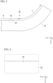
FIG. 8 is a photograph showing a light source image of a light emitting part when the light guide body emits light, which is an example. -
FIG. 9 is a photograph showing a light source image of a light emitting part when a light guide body emits light, which is a comparative example. -
FIG. 10 is a cross-sectional view of a light guide body included in a vehicle lamp according to a second embodiment of the present invention. - Hereinafter, embodiments of the present invention will be described with reference to the accompanying drawings in detail.
- Further, in the drawings used in the following description, in order to make each component easier to see, dimensions may be shown at different scales depending on the component, and dimensional ratios of each component may not be the same as the actual ones.
- First, as a first embodiment of the present invention, for example, a
vehicle lamp 1A shown inFIG. 1 to FIG. 7 will be described. - Further,
FIG. 1 is a front view showing a configuration of thevehicle lamp 1A.FIG. 2 is a plan view showing the configuration of thevehicle lamp 1B.FIG. 3 is a cross-sectional view of alight guide body 3A along a line segment III-III shown inFIG. 1 .FIG. 4 is an enlarged cross-sectional view of thelight guide body 3A showing a boxed portion IV shown inFIG. 3 .FIG. 5 is a cross-sectional view of thelight guide body 3A along a line segment V-V shown inFIG. 2 .FIG. 6 is a cross-sectional view of thelight guide body 3A along a line segment VI-VI shown inFIG. 2 .FIG. 7 is a cross-sectional view of thelight guide body 3A along a line segment VII-VII shown inFIG. 2 . - In addition, in the drawing described below, an XYZ orthogonal coordinate system is set, an X-axis direction indicates a forward/rearward direction of the
vehicle lamp 1A, a Y-axis direction indicates a leftward/rightward direction of thevehicle lamp 1A, and a Z-axis direction indicates an upward/downward direction of thevehicle lamp 1A. - As shown in
FIG. 1 andFIG. 2 , the vehicle lamp 1 of the embodiment includes alight source 2, and thelight guide body 3A having a rod shape, light L emitted from thelight source 2 enters thelight guide body 3A from anincident part 4 provided on a base end side of thelight guide body 3A, the light L is guided toward a tip side of thelight guide body 3A, and the light L reflected by a plurality ofreflection cuts 5a provided on a back surface side of thelight guide body 3A is emitted to the outside of thelight guide body 3A from a front surface side of thelight guide body 3A, thereby causing alight emitting part 6 provided on the front surface side of thelight guide body 3A to emit light. - The
light source 2 is constituted by for example, LEDs, is mounted on a surface of a circuit board (not shown) on which a driving circuit configured to drive the LED is provided, and radially emits the light L toward the base end side of the light guide body 3. - The
light guide body 3A is formed of a light transmitting member, for example, a transparent resin such as polycarbonate, acryl, or the like, glass, or the like. - The
incident part 4 has a flat (planar)incidence surface 4a located on the base end side of thelight guide body 3A and facing thelight source 2. Theincident part 4 causes the light L emitted from thelight source 2 to enter thelight guide body 3A from theincidence surface 4a. Further, theincident part 4 is not limited to the configuration having the above-mentioned flat (planar)incidence surface 4a, and may have a configuration having a lens shape that causes the light L enter thelight guide body 3A while parallelizing and condensing the light L radially emitted from thelight source 2. - As shown in
FIG. 3 and FIG. 4 , the plurality ofreflection cuts 5a may have any structure as long as the light L entering the back surface side of thelight guide body 3A is reflected from the front surface side of thelight guide body 3A at an angle where the light is emitted (transmitted) to the outside, and there are no particular limitations on the shape, size, number, or the like. - In the embodiment, for example, the reflection cuts 5a having a substantially triangular cross section formed by cutting out a central portion on the back surface side of the
light guide body 3A in a vertical direction (the upward/downward direction in the embodiment) perpendicular to the axial direction of thelight guide body 3A are arranged in the axial direction of thelight guide body 3A (the leftward/rightward direction in the embodiment). - In addition, since the plurality of
reflection cuts 5a cause thelight emitting part 6 to more uniformly emit light in the axial direction of thelight guide body 3A, which will be described below, adjacent intervals gradually become narrower from the base end side to the tip side of thelight guide body 3A. - A pair of
reflective surfaces 5b are provided on both sides with the central portion (the plurality ofreflection cuts 5a) of the back surface side of thelight guide body 3A sandwiched therebetween. The pair ofreflective surfaces 5b are constituted by concave curved surfaces, which are curved in an arc shape, in a cross section in the vertical direction (hereinafter, referred to as "a vertical cross section") perpendicular to the axial direction of thelight guide body 3A. - As shown in
FIG. 1 ,FIG. 2 andFIG. 7 , thelight emitting part 6 has anemission surface 6a located on the front surface side of thelight guide body 3A and continuous with thelight guide body 3A in the axial direction. Theemission surface 6a is constituted by a convex curved surface, which is curved in an arc shape, in the vertical cross section of thelight guide body 3A. - Further, the
emission surface 6a may be provided with a plurality of diffusion cuts (not shown) configured to diffuse the light L emitted from theemission surface 6a toward the outside. The diffusion cut may include, for example, a concavo-convex structure or the like formed by performing lens cutting referred to as flute cutting or fish eye cutting, knurling, embossing, or the like. In addition, it is possible to control a diffusion degree of the light L emitted from theemission surface 6a by adjusting a shape or the like of the diffusion cut. - Incidentally, as shown in
FIG. 1 andFIG. 2 , the vehicle lamp 1 of the embodiment has acurved part 7 in which a part of thelight guide body 3A is curved between theincident part 4 and thelight emitting part 6, and anextension portion 8 in which the plurality ofreflection cuts 5a and thelight emitting part 6 are provided. That is, thelight guide body 3A extends forward from a position facing thelight source 2, is curved by thecurved part 7, and then, has an elongated shape in which theextension portion 8 extends in a widthwise direction of the vehicle. - Further, an angle range in which the
curved part 7 is curved is preferably equal to or greater than 60°, and a curvature of thecurved part 7 is preferably equal to or greater than R18.5 on the central axis. - In addition, as shown in
FIG. 1 ,FIG. 2 andFIG. 6 , thelight guide body 3A has a pair of (two)upright walls 9 standing up from the front surface side of thecurved part 7 by cutting out both sides with the central portion on the front surface side of thecurved part 7 sandwiched therebetween in the axial direction. - The pair of
upright walls 9 are provided on both side surfaces of aconvex portion 10 formed by cutting out both sides with the central portion of the front surface side of thecurved part 7 sandwiched therebetween in the axial direction. That is, the pair ofupright walls 9 are formed rising parallel to each other from the front surface side of thecurved part 7 while facing each other on both side surfaces of theconvex portion 10. - Further, the pair of
upright walls 9 are not limited to those that stand up parallel to each other on both side surfaces of theconvex portion 10 described above, and may be formed to be inclined with respect to each other. In addition, the pair ofupright walls 9 are not limited to a flat surface, but may be a curved surface that is curved into a convex shape or a concave shape. - In addition, as shown in
FIG. 1 ,FIG. 2 ,FIG. 5 and FIG. 6 , in order to cause thelight emitting part 6 to emit the light L more uniformly, a plurality of diffusion/reflection cuts 11 configured to diffuse and reflect the light L guided into thecurved part 7 in the vertical direction of thelight guide body 3A are provided on the front surface side of thecurved part 7 in the vertical direction of thelight guide body 3A. - The plurality of diffusion/
reflection cuts 11 are constituted by a plurality of knurlings extending in the axial direction of thecurved part 7 and arranged in a direction perpendicular to the axial direction of thecurved part 7. That is, each of the diffusion/reflection cuts 11 is constituted by a convex curved surface that is curved in an arc shape in the vertical cross section of thelight guide body 3A. Further, the diffusion/reflection cuts 11 are not limited to the configuration in which the knurlings curved in the above-mentioned convex shape are arranged as described above and may have a configuration in which knurlings curved in a concave shape are arranged or may have a configuration in which these convex and concave knurlings are alternately arranged. - In the
vehicle lamp 1A of the embodiment having the above-mentioned configuration, as shown inFIG. 6 , the pair ofupright walls 9 form a reflective surface configured to reflect the light L guided in thecurved part 7. Accordingly, even when the length of thecurved part 7 is short and the curvature is small, some of the light L guided in thecurved part 7 does not go toward the tip side of thelight guide body 3A, and it is possible to guide the light toward the tip side of thelight guide body 3A while suppressing leakage of stray light from the base end side of thelight emitting part 6 to the outside. - Accordingly, in the
vehicle lamp 1A of the embodiment, it is possible to prevent luminance unevenness from occurring in thelight emitting part 6 due to the so-called point light in which a part of the base end side of thelight emitting part 6 appears to shine more intensely than the surrounding area. - Here, as an example, a light source image of the
light emitting part 6 when thelight guide body 3A emits light was obtained by simulation. The light source image of the light emitting part according to the simulation result is shown inFIG. 8 . - Meanwhile, as a comparative example, the light source image of the
light emitting part 6 when the light guide body having basically the same shape as thelight guide body 3A except that the pair ofupright walls 9 located on the front surface side of thecurved part 7 are omitted (thecurved part 7 has a uniform cross-sectional shape shown inFIG. 5 ) emits light was obtained by simulation. The light source image of the light emitting part according to the simulation is shown inFIG. 9 . - In the
light guide body 3A that is the example, as shown inFIG. 8 , it can be seen that there is no point light and thelight emitting part 6 emits light uniformly. Meanwhile, in the light guide body that is the comparative example, as shown inFIG. 9 , it can be seen that the point light is generated on the base end side of thelight emitting part 6. - As described above, in the
vehicle lamp 1A of the embodiment, it is possible to cause thelight emitting part 6 to cause emit light uniformly, and improve appearance upon emission of thelight emitting part 6. - Next, as a second embodiment of the present invention, for example, a
vehicle lamp 1B shown inFIG. 10 will be described. - Further,
FIG. 10 is a cross-sectional view of alight guide body 3B provided in thevehicle lamp 1B. In addition, in the following description, the same parts as in thevehicle lamp 1A are designated by the same reference signs and description thereof will be omitted. - The
vehicle lamp 1B of the embodiment includes thelight guide body 3B as shown inFIG. 10 , instead of thelight guide body 3A. Other than that, thevehicle lamp 1B has basically the same configuration as thevehicle lamp 1A described above. - Specifically, in the
light guide body 3B, as shown inFIG. 10 , a pair of (two)upright walls 9 are provided on both side surfaces of aconcave portion 12 formed by cutting out a central portion of thecurved part 7 on the front surface side in the axial direction. That is, the pair ofupright walls 9 are formed on both side surfaces of theconcave portion 12, facing each other and rising in parallel from the front surface side of thecurved part 7. - In the
vehicle lamp 1B of the embodiment having the above-mentioned configuration, the pair ofupright walls 9 form a reflective surface configured to reflect the light L guided in thecurved part 7. Accordingly, even when the length of thecurved part 7 is short and the curvature is small, some of the light L guided in thecurved part 7 does not go toward the tip side of thelight guide body 3A, and it is possible to guide the light toward the tip side of thelight guide body 3A while suppressing leakage of stray light from the base end side of thelight emitting part 6 to the outside. - Accordingly, in the
vehicle lamp 1B of the embodiment, it is possible to prevent luminance unevenness from occurring in thelight emitting part 6 due to the so-called point light in which a part of the base end side of thelight emitting part 6 appears to shine more intensely than the surrounding area. - As described above, in the
vehicle lamp 1B of the embodiment, it is possible to cause thelight emitting part 6 to emit light more uniformly and improve appearance upon emission of thelight emitting part 6. - Further, the present invention is not necessarily limited to the embodiment, and various changes may be added without departing from the scope of the present invention.
- For example, while the pair of (two)
upright walls 9 are provided on both side surfaces of theconvex portion 10 formed by cutting out both side with the central portion of thecurved part 7 on the front surface side sandwiched therebetween in the axial direction, or both side surfaces of theconcave portion 12 formed by cutting out the central portion of thecurved part 7 on the front surface side in the axial direction, it is possible to obtain the effect of the reflective surface provided by the above-mentionedupright walls 9 by providing at least one or more of theupright walls 9. In addition, by providing the plurality ofconvex portions 10 orconcave portions 12, the number of theupright walls 9 can also be increased. - Further, a reflector facing a back surface of the
light guide body vehicle lamp light guide body light guide body - In addition, in the vehicle lamp 1, the shape of the
light guide body light guide body - Further, the vehicle lamp to which the present invention is applied is not particularly limited, and the present invention can be widely applied to, for example, taillights (tail lamps), width indicators (position lamps), daytime running lamps (DRL), back lamps, direction indicators (blinker lamps), side marker lamps, or the like.
- In addition, the
light source 2 may be anything that emits the light L radially, and in addition to the above-mentioned LED, for example, a light emitting element such as a laser diode (LD) or the like can be used. In addition, the color of the light emitted from thelight source 2 can be changed as appropriate to red light, white light, orange light, or the like, depending on the purpose of the vehicle lamp. -
- 1A, 1B Vehicle lamp
- 2 Light source
- 3A, 3B Light guide body
- 4 Incident part
- 5a Reflection cut
- 6 Light emitting part
- 7 Curved part
- 8 Extension portion
- 9 Upright wall
- 10 Convex portion
- 11 Diffusion/reflection cut
- 12 Concave portion
- L Light
Claims (6)
- A vehicle lamp that includes a light source and a rod-shaped light guide body, and that is configured to cause light emitted from the light source to enter the light guide body from an incident part provided on a base end side of the light guide body, guide the light toward a tip side of the light guide body, and emit the light reflected by a plurality of reflection cuts provided on a back surface side of the light guide body from a front surface side of the light guide body to the outside of the light guide body, thereby causing a light emitting part provided on the front surface side of the light guide body to emit light, the vehicle lamp further including:a curved part in which a part of the light guide body is curved between the incident part and the light emitting part; andan upright wall standing up from a front surface side of the curved part by cutting out a part of the curved part on the front surface side in an axial direction,wherein the upright wall forms a reflective surface that reflects light guided in the curved part.
- The vehicle lamp according to claim 1, wherein two of the upright walls facing each other are provided in a central portion of the curved part on a front surface side.
- The vehicle lamp according to claim 2, wherein the upright walls are provided on both side surfaces of a convex portion which is formed by cutting out both sides of the central portion of the curved part on the front surface side in the axial direction.
- The vehicle lamp according to claim 2, wherein the upright walls are provided on both side surfaces of a concave portion which is formed by cutting out the central portion of the curved part on the front surface side in the axial direction.
- The vehicle lamp according to any one of claims 1 to 4, wherein a plurality of diffusion/reflection cuts are provided on a front surface side of the curved part.
- The vehicle lamp according to claim 5, wherein the plurality of diffusion/reflection cuts are constituted by a plurality of knurlings extending in the axial direction of the curved part and arranged in a direction perpendicular to the axial direction of the curved part.
Applications Claiming Priority (2)
| Application Number | Priority Date | Filing Date | Title |
|---|---|---|---|
| JP2022037160A JP7702370B2 (en) | 2022-03-10 | 2022-03-10 | Vehicle lighting fixtures |
| PCT/JP2023/007786 WO2023171523A1 (en) | 2022-03-10 | 2023-03-02 | Vehicle lamp |
Publications (2)
| Publication Number | Publication Date |
|---|---|
| EP4491940A1 true EP4491940A1 (en) | 2025-01-15 |
| EP4491940A4 EP4491940A4 (en) | 2025-09-03 |
Family
ID=87935317
Family Applications (1)
| Application Number | Title | Priority Date | Filing Date |
|---|---|---|---|
| EP23766699.5A Pending EP4491940A4 (en) | 2022-03-10 | 2023-03-02 | VEHICLE LIGHT |
Country Status (5)
| Country | Link |
|---|---|
| US (1) | US20250189095A1 (en) |
| EP (1) | EP4491940A4 (en) |
| JP (1) | JP7702370B2 (en) |
| CN (1) | CN118742768A (en) |
| WO (1) | WO2023171523A1 (en) |
Family Cites Families (9)
| Publication number | Priority date | Publication date | Assignee | Title |
|---|---|---|---|---|
| JP5938228B2 (en) | 2012-02-20 | 2016-06-22 | 株式会社小糸製作所 | Light guide member and vehicle lamp |
| JP6303305B2 (en) * | 2013-07-08 | 2018-04-04 | 市光工業株式会社 | Light guide and vehicle lamp using the light guide |
| US9651211B2 (en) * | 2014-10-16 | 2017-05-16 | Valeo North America, Inc. | Multi-function optical system with shared exit optic |
| JP6490432B2 (en) | 2015-01-26 | 2019-03-27 | スタンレー電気株式会社 | Lighting device |
| JP7061461B2 (en) | 2015-02-18 | 2022-04-28 | マサチューセッツ インスティテュート オブ テクノロジー | Water-soluble transmembrane protein and its preparation and usage |
| AT518163B1 (en) * | 2016-02-17 | 2017-08-15 | Zkw Group Gmbh | Light guide for a vehicle headlight |
| FR3064756A1 (en) * | 2017-03-31 | 2018-10-05 | Valeo Vision | GUIDE LIGHT CURVE PROPAGATOR OF BRIGHT RAYS |
| JP2019008933A (en) * | 2017-06-22 | 2019-01-17 | スタンレー電気株式会社 | Vehicle lighting |
| FR3105355B1 (en) * | 2019-12-20 | 2022-07-15 | Valeo Vision Belgique | LIGHT GUIDE WITH PARTIAL COLLIMATION ENTRANCE FACE |
-
2022
- 2022-03-10 JP JP2022037160A patent/JP7702370B2/en active Active
-
2023
- 2023-03-02 EP EP23766699.5A patent/EP4491940A4/en active Pending
- 2023-03-02 WO PCT/JP2023/007786 patent/WO2023171523A1/en not_active Ceased
- 2023-03-02 CN CN202380016014.XA patent/CN118742768A/en active Pending
- 2023-03-02 US US18/843,304 patent/US20250189095A1/en not_active Abandoned
Also Published As
| Publication number | Publication date |
|---|---|
| CN118742768A (en) | 2024-10-01 |
| WO2023171523A1 (en) | 2023-09-14 |
| JP2023132058A (en) | 2023-09-22 |
| JP7702370B2 (en) | 2025-07-03 |
| US20250189095A1 (en) | 2025-06-12 |
| EP4491940A4 (en) | 2025-09-03 |
Similar Documents
| Publication | Publication Date | Title |
|---|---|---|
| US10816159B2 (en) | Vehicle lamp | |
| US12601461B2 (en) | Vehicle lamp | |
| JP2018120683A (en) | Vehicle lighting | |
| JP2018137127A (en) | Vehicular lighting fixture | |
| US12215838B2 (en) | Lighting tool for vehicle | |
| US20250189095A1 (en) | Vehicle lamp | |
| WO2023210343A1 (en) | Vehicle lamp | |
| US20230324021A1 (en) | Lighting tool for vehicle | |
| JP7770154B2 (en) | Vehicle lighting fixtures | |
| JP2020038769A (en) | Vehicle lighting | |
| JP7764213B2 (en) | Vehicle lighting fixtures | |
| EP3578877A1 (en) | Vehicular lamp | |
| US12442505B2 (en) | Vehicle lamp | |
| US20260132904A1 (en) | Vehicle lamp | |
| US20260055868A1 (en) | Vehicle lamp | |
| JP7317679B2 (en) | vehicle lamp | |
| JP2024147879A (en) | Vehicle lighting fixtures | |
| US12247713B2 (en) | Lighting tool for vehicle | |
| US20260055867A1 (en) | Vehicle lamp | |
| JP7417412B2 (en) | Vehicle lights | |
| JP7347968B2 (en) | Vehicle lights | |
| JP2024038740A (en) | Vehicle lights | |
| JP2023170849A (en) | Vehicle lights | |
| WO2023105962A1 (en) | Vehicle lamp | |
| JP2024035419A (en) | Vehicle lights |
Legal Events
| Date | Code | Title | Description |
|---|---|---|---|
| STAA | Information on the status of an ep patent application or granted ep patent |
Free format text: STATUS: THE INTERNATIONAL PUBLICATION HAS BEEN MADE |
|
| PUAI | Public reference made under article 153(3) epc to a published international application that has entered the european phase |
Free format text: ORIGINAL CODE: 0009012 |
|
| STAA | Information on the status of an ep patent application or granted ep patent |
Free format text: STATUS: REQUEST FOR EXAMINATION WAS MADE |
|
| 17P | Request for examination filed |
Effective date: 20240805 |
|
| AK | Designated contracting states |
Kind code of ref document: A1 Designated state(s): AL AT BE BG CH CY CZ DE DK EE ES FI FR GB GR HR HU IE IS IT LI LT LU LV MC ME MK MT NL NO PL PT RO RS SE SI SK SM TR |
|
| DAV | Request for validation of the european patent (deleted) | ||
| DAX | Request for extension of the european patent (deleted) | ||
| A4 | Supplementary search report drawn up and despatched |
Effective date: 20250801 |
|
| RIC1 | Information provided on ipc code assigned before grant |
Ipc: F21S 43/237 20180101AFI20250728BHEP Ipc: F21S 43/245 20180101ALI20250728BHEP Ipc: F21S 43/247 20180101ALI20250728BHEP Ipc: F21V 8/00 20060101ALI20250728BHEP Ipc: F21W 103/00 20180101ALI20250728BHEP Ipc: F21W 103/10 20180101ALI20250728BHEP Ipc: F21W 103/15 20180101ALI20250728BHEP Ipc: F21W 103/20 20180101ALI20250728BHEP Ipc: F21W 103/45 20180101ALI20250728BHEP Ipc: F21W 103/55 20180101ALI20250728BHEP Ipc: F21Y 115/10 20160101ALI20250728BHEP Ipc: F21Y 115/30 20160101ALI20250728BHEP Ipc: G02B 6/00 20060101ALI20250728BHEP |