EP4491892A1 - Threaded fasteners - Google Patents
Threaded fasteners Download PDFInfo
- Publication number
- EP4491892A1 EP4491892A1 EP24187500.4A EP24187500A EP4491892A1 EP 4491892 A1 EP4491892 A1 EP 4491892A1 EP 24187500 A EP24187500 A EP 24187500A EP 4491892 A1 EP4491892 A1 EP 4491892A1
- Authority
- EP
- European Patent Office
- Prior art keywords
- shank
- fastener
- helical thread
- thread formation
- formation
- Prior art date
- Legal status (The legal status is an assumption and is not a legal conclusion. Google has not performed a legal analysis and makes no representation as to the accuracy of the status listed.)
- Pending
Links
Images





Classifications
-
- F—MECHANICAL ENGINEERING; LIGHTING; HEATING; WEAPONS; BLASTING
- F16—ENGINEERING ELEMENTS AND UNITS; GENERAL MEASURES FOR PRODUCING AND MAINTAINING EFFECTIVE FUNCTIONING OF MACHINES OR INSTALLATIONS; THERMAL INSULATION IN GENERAL
- F16B—DEVICES FOR FASTENING OR SECURING CONSTRUCTIONAL ELEMENTS OR MACHINE PARTS TOGETHER, e.g. NAILS, BOLTS, CIRCLIPS, CLAMPS, CLIPS OR WEDGES; JOINTS OR JOINTING
- F16B25/00—Screws that cut thread in the body into which they are screwed, e.g. wood screws
- F16B25/001—Screws that cut thread in the body into which they are screwed, e.g. wood screws characterised by the material of the body into which the screw is screwed
- F16B25/0026—Screws that cut thread in the body into which they are screwed, e.g. wood screws characterised by the material of the body into which the screw is screwed the material being a hard non-organic material, e.g. stone, concrete or drywall
-
- F—MECHANICAL ENGINEERING; LIGHTING; HEATING; WEAPONS; BLASTING
- F16—ENGINEERING ELEMENTS AND UNITS; GENERAL MEASURES FOR PRODUCING AND MAINTAINING EFFECTIVE FUNCTIONING OF MACHINES OR INSTALLATIONS; THERMAL INSULATION IN GENERAL
- F16B—DEVICES FOR FASTENING OR SECURING CONSTRUCTIONAL ELEMENTS OR MACHINE PARTS TOGETHER, e.g. NAILS, BOLTS, CIRCLIPS, CLAMPS, CLIPS OR WEDGES; JOINTS OR JOINTING
- F16B25/00—Screws that cut thread in the body into which they are screwed, e.g. wood screws
- F16B25/0036—Screws that cut thread in the body into which they are screwed, e.g. wood screws characterised by geometric details of the screw
- F16B25/0042—Screws that cut thread in the body into which they are screwed, e.g. wood screws characterised by geometric details of the screw characterised by the geometry of the thread, the thread being a ridge wrapped around the shaft of the screw
-
- F—MECHANICAL ENGINEERING; LIGHTING; HEATING; WEAPONS; BLASTING
- F16—ENGINEERING ELEMENTS AND UNITS; GENERAL MEASURES FOR PRODUCING AND MAINTAINING EFFECTIVE FUNCTIONING OF MACHINES OR INSTALLATIONS; THERMAL INSULATION IN GENERAL
- F16B—DEVICES FOR FASTENING OR SECURING CONSTRUCTIONAL ELEMENTS OR MACHINE PARTS TOGETHER, e.g. NAILS, BOLTS, CIRCLIPS, CLAMPS, CLIPS OR WEDGES; JOINTS OR JOINTING
- F16B25/00—Screws that cut thread in the body into which they are screwed, e.g. wood screws
- F16B25/0036—Screws that cut thread in the body into which they are screwed, e.g. wood screws characterised by geometric details of the screw
- F16B25/0042—Screws that cut thread in the body into which they are screwed, e.g. wood screws characterised by geometric details of the screw characterised by the geometry of the thread, the thread being a ridge wrapped around the shaft of the screw
- F16B25/0052—Screws that cut thread in the body into which they are screwed, e.g. wood screws characterised by geometric details of the screw characterised by the geometry of the thread, the thread being a ridge wrapped around the shaft of the screw the ridge having indentations, notches or the like in order to improve the cutting behaviour
-
- F—MECHANICAL ENGINEERING; LIGHTING; HEATING; WEAPONS; BLASTING
- F16—ENGINEERING ELEMENTS AND UNITS; GENERAL MEASURES FOR PRODUCING AND MAINTAINING EFFECTIVE FUNCTIONING OF MACHINES OR INSTALLATIONS; THERMAL INSULATION IN GENERAL
- F16B—DEVICES FOR FASTENING OR SECURING CONSTRUCTIONAL ELEMENTS OR MACHINE PARTS TOGETHER, e.g. NAILS, BOLTS, CIRCLIPS, CLAMPS, CLIPS OR WEDGES; JOINTS OR JOINTING
- F16B25/00—Screws that cut thread in the body into which they are screwed, e.g. wood screws
- F16B25/0036—Screws that cut thread in the body into which they are screwed, e.g. wood screws characterised by geometric details of the screw
- F16B25/0042—Screws that cut thread in the body into which they are screwed, e.g. wood screws characterised by geometric details of the screw characterised by the geometry of the thread, the thread being a ridge wrapped around the shaft of the screw
- F16B25/0057—Screws that cut thread in the body into which they are screwed, e.g. wood screws characterised by geometric details of the screw characterised by the geometry of the thread, the thread being a ridge wrapped around the shaft of the screw the screw having distinct axial zones, e.g. multiple axial thread sections with different pitch or thread cross-sections
-
- F—MECHANICAL ENGINEERING; LIGHTING; HEATING; WEAPONS; BLASTING
- F16—ENGINEERING ELEMENTS AND UNITS; GENERAL MEASURES FOR PRODUCING AND MAINTAINING EFFECTIVE FUNCTIONING OF MACHINES OR INSTALLATIONS; THERMAL INSULATION IN GENERAL
- F16B—DEVICES FOR FASTENING OR SECURING CONSTRUCTIONAL ELEMENTS OR MACHINE PARTS TOGETHER, e.g. NAILS, BOLTS, CIRCLIPS, CLAMPS, CLIPS OR WEDGES; JOINTS OR JOINTING
- F16B25/00—Screws that cut thread in the body into which they are screwed, e.g. wood screws
- F16B25/0036—Screws that cut thread in the body into which they are screwed, e.g. wood screws characterised by geometric details of the screw
- F16B25/0042—Screws that cut thread in the body into which they are screwed, e.g. wood screws characterised by geometric details of the screw characterised by the geometry of the thread, the thread being a ridge wrapped around the shaft of the screw
- F16B25/0068—Screws that cut thread in the body into which they are screwed, e.g. wood screws characterised by geometric details of the screw characterised by the geometry of the thread, the thread being a ridge wrapped around the shaft of the screw with multiple-threads, e.g. a double thread screws
-
- F—MECHANICAL ENGINEERING; LIGHTING; HEATING; WEAPONS; BLASTING
- F16—ENGINEERING ELEMENTS AND UNITS; GENERAL MEASURES FOR PRODUCING AND MAINTAINING EFFECTIVE FUNCTIONING OF MACHINES OR INSTALLATIONS; THERMAL INSULATION IN GENERAL
- F16B—DEVICES FOR FASTENING OR SECURING CONSTRUCTIONAL ELEMENTS OR MACHINE PARTS TOGETHER, e.g. NAILS, BOLTS, CIRCLIPS, CLAMPS, CLIPS OR WEDGES; JOINTS OR JOINTING
- F16B25/00—Screws that cut thread in the body into which they are screwed, e.g. wood screws
- F16B25/0036—Screws that cut thread in the body into which they are screwed, e.g. wood screws characterised by geometric details of the screw
- F16B25/0042—Screws that cut thread in the body into which they are screwed, e.g. wood screws characterised by geometric details of the screw characterised by the geometry of the thread, the thread being a ridge wrapped around the shaft of the screw
- F16B25/0057—Screws that cut thread in the body into which they are screwed, e.g. wood screws characterised by geometric details of the screw characterised by the geometry of the thread, the thread being a ridge wrapped around the shaft of the screw the screw having distinct axial zones, e.g. multiple axial thread sections with different pitch or thread cross-sections
- F16B25/0063—Screws that cut thread in the body into which they are screwed, e.g. wood screws characterised by geometric details of the screw characterised by the geometry of the thread, the thread being a ridge wrapped around the shaft of the screw the screw having distinct axial zones, e.g. multiple axial thread sections with different pitch or thread cross-sections with a non-threaded portion on the shaft of the screw
-
- F—MECHANICAL ENGINEERING; LIGHTING; HEATING; WEAPONS; BLASTING
- F16—ENGINEERING ELEMENTS AND UNITS; GENERAL MEASURES FOR PRODUCING AND MAINTAINING EFFECTIVE FUNCTIONING OF MACHINES OR INSTALLATIONS; THERMAL INSULATION IN GENERAL
- F16B—DEVICES FOR FASTENING OR SECURING CONSTRUCTIONAL ELEMENTS OR MACHINE PARTS TOGETHER, e.g. NAILS, BOLTS, CIRCLIPS, CLAMPS, CLIPS OR WEDGES; JOINTS OR JOINTING
- F16B25/00—Screws that cut thread in the body into which they are screwed, e.g. wood screws
- F16B25/10—Screws performing an additional function to thread-forming, e.g. drill screws or self-piercing screws
- F16B25/106—Screws performing an additional function to thread-forming, e.g. drill screws or self-piercing screws by means of a self-piercing screw-point, i.e. without removing material
Definitions
- Threaded fasteners are widely commercially used throughout the world for securing various objects to various substrates.
- Various threaded fasteners include a head, a shank, and one or more thread formations extending from the shank for frictionally engaging the substrate into which the threaded fastener is driven.
- threaded fasteners are used to secure objects to concrete, masonry, and other cementitious substrates.
- the threads of the thread formation(s) of the threaded fastener grip the inside surfaces of the substrate that define the cavity (such as the surfaces that define a pre-drilled hole in the substrate), causing the threaded fastener to be driven deeper into the substrate until the head of the threaded fastener comes into contact with the object being connected by the threaded fastener to the substrate (such as a bracket, flange, clip, or other mechanical device having a hole in it through which the shank of the fastener passes).
- a threaded fastener can experience frictional resistance forces that tend to impede the driving of the threaded fastener into the substrate. This can impart significant torsional stresses on the threaded fastener, placing the shank of the threaded fastener under shearing torsional stresses. These torsional stresses can be so great in certain circumstances such that they cause the threaded fastener to fail due to the forces placed on the shank of the threaded fastener. Certain failures can result in the shank breaking and the fastener having to be removed. These failures can occur in various sections of the shank.
- the fastener includes a head and a shank connected to the head at a first end of the shank.
- the shank includes a first portion, a second portion, a third portion, and a tip at an end of the shank opposite the head.
- the fastener includes a first helical thread formation extending outwardly from the second and third portions of the shank.
- the fastener includes a second helical thread formation extending outwardly from a section of the third portion of the shank that is adjacent to the tip.
- the first helical thread formation defines grooves in the section of the third portion of the shank that is adjacent to the tip.
- mounting methods such as mounted, connected, etc.
- mounting methods are not intended to be limited to direct mounting methods but should be interpreted broadly to include indirect and operably mounted, connected, and like mounting methods.
- This specification is intended to be taken as a whole and interpreted in accordance with the principles of the present disclosure and as understood by one of ordinary skill in the art.
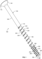
- a threaded fastener 100 of one example embodiment of the present disclosure is shown in Figs. 1 , 2 , 3 , 4 , 5 , 6 , 7 , 8 , 9 , 10 , 11 , and 12 .
- the threaded fastener 100 may sometimes be referred to herein as the "fastener” for brevity.
- the fastener 100 is configured for use to secure an object to a substrate (such as but not limited to a concrete, masonry, and other cementitious substrate).
- the threaded fastener 100 includes a head 110, a shank 150 connected to the head 110, and thread formations 220 and 260 connected to and extending outwardly from the shank 150.
- the head 110, the shank 150, and the thread formations 220 and 260 are monolithically formed from a metal material such as steel.
- the steel is an AISI 1022 low carbon steel.
- the configuration of the threaded fastener 100 of the present disclosure maximizes the material used for the formation of the shank 150 while still providing the head 110 and the thread formations 220 and 260 that provide their desired functionality for the fastener 100.
- the present disclosure takes into account that for the formation of fastener, only a limited amount of material (such as steel) can be used to create the fastener, and specifically that during the formation process, only that limited amount of material can be used to form the head, the shank, and the thread formation(s) of the fastener.
- a limited amount of material such as steel
- the material for those four thread formations needs to come from the head or the shank, and thus the shank may need to be narrower.
- the present disclosure provides for a configuration of the fastener 100 including its head 110, its shank 150, and its thread formations 220 and 260 that provide the desired functionalities needed from the head 110 and the thread formations 220 and 260 while still maximizing the diameter and strength of the shank 150.
- the bottom portion 140 of the head 110 includes a bottom surface (not separately labeled). The bottom surface generally faces away from the head 110 and towards the shank 150.
- the bottom portion 140 can include a plurality of ribs (not shown) extending from the bottom surface. In various such embodiments, the ribs can be arranged radially around a central axisA1 of the fastener 100 and thus the head 110 (which would extend through line A1-A1).
- the head 110 can be alternatively configured in accordance with the present disclosure.
- the first shank portion 160 includes a first end (not labeled) connected to the head 110 (at a first end of the shank 150) and a second end (not labeled) connected to the second shank portion 170.
- the first shank portion 160 has a constant or substantially constant outer diameter along the length of the first shank portion 160. In this embodiment, no thread formations extend from the first shank portion 160.
- the third shank portion 180 includes a first end (not labeled) connected to the second shank portion 170 and a second end (not labeled) connected to the tip 190.
- the tip 190 includes a first end (not labeled) connected to the third shank portion 180 and a pointed second end 196.
- the third shank portion 180 has a constant or substantially constant outer diameter along the length of the third shank portion 180.
- part of the first thread formation 220 extends from the third shank portion 180
- the second thread formation 260 extends from the part of the third shank portion 180.
- the tip 190 is pointed to aid in penetrating the substrate in which the fastener 100 is being driven.
- the tip 190 can be alternatively configured in accordance with the present disclosure.
- the tip 190 has a decreasing outer diameter from section thereof connected to the third shank portion 180 to the tip 196 thereof.
- the shank 150 has a longitudinal axis A1 extending along the length L of the shank 150 from the head 110 to the end of the pointed second end 196 of the tip 190.
- the outer diameter of the first shank portion 160 is 0.148 inches (3.7592 mm) and the outer diameter of the third shank portion 180 is 0.133 inches (3.3528 mm).
- the outer diameter of the first shank portion 160 is 0.189 inches (4.8006 mm) and the outer diameter of the third shank portion 180 is 0.173 inches (4.3942 mm).
- the fastener 100 includes a first helical thread formation 220 connected to, extending along, and extending outwardly from the second portion 170 of the shank 150 and from the third portion 180 of the shank 150.
- the first helical thread formation 220 includes a plurality of threads (not individually labeled) that span all or substantially all of the second and third portions 170 and 180 of the shank 150.
- the first helical thread formation 220 extends along the second and third portions 170 and 180 of the shank 150 in a helical or spiral formation in the direction of the longitudinal axis A1 of the fastener 100.
- the first helical thread formation 220 includes a root 222 adjacent the outer surfaces (not labeled) of the second and third portions 170 and 180 of the shank 150.
- the first helical thread formation 220 includes a trailing surface 224 extending from the root 222 to the crest 230 (at a 110 degree angle or approximately a 110 degree angle relative to the outer surface of the third portion 180 of the shank 150 in this example embodiment).
- the first helical thread formation 220 includes a leading surface 226 extending from the root 222 to the crest 230 (at a 110 degree angle or approximately a 110 degree angle relative to the outer surface of the third portion 180 of the shank 150 in this example embodiment).
- the material that could be used for the first helical thread formation 220 to make these angles larger is rather used for increasing the outer diameter of the shank 150 and thus making the shank 150 stronger.
- the first helical thread formation 220 has a 0.129 inch (3.2766 mm) pitch length.
- the first helical thread formation 220 has a 0.133 inch (3.3782 mm) pitch length.
- the first helical thread formation 220 has an outer 0.208 inch (5.2832 mm) diameter.
- the first helical thread formation 220 has an outer 0.250 inch (6.35 mm) diameter.
- the outer diameter of the first helical thread formation 220 is substantially constant along the length of the second portion 170 and the third portion 180 of the shank 150 (except for the leading and terminating sections thereof that are downwardly tapered toward the shank 150).
- the first helical thread formation 220 includes a first thread portion 240 and a second thread portion 250.
- the second thread portion 250 extends for the bottom three pitch lengths of the first helical thread formation 220 that are adjacent the tip 190.
- the first thread portion 240 extends for the rest of the pitch lengths of the first helical thread formation 220.
- the first thread portion 240 of the first helical thread formation 220 does not define any include any grooves. This reduces the torsional forces on this second portion 170 of shank 150 and on the upper section of the third portion 180 of the shank 150.
- the second thread portion 250 of the first helical thread formation 220 defines a plurality of spaced-apart grooves.
- the grooves are each partially defined by a first cutting surface (not labeled) and a second cutting surface (not labeled). It should be appreciated that the surfaces that define each groove can vary in accordance with the present disclosure. It should be appreciated that all of the grooves are identically configured in this example embodiment, but that one or more of the grooves may be alternatively configured.
- the fastener 100 also includes a second helical thread formation 260 connected to, extending along, and extending outwardly from a lower section of the third portion 180 of the shank 150 adjacent the tip 190.
- the second helical thread formation 260 includes a plurality of threads (not individually labeled) that extend along a lower section of the third portion 170 of the shank 150 in a helical or spiral formation in the direction of the longitudinal axis A1 of the fastener 100.
- the second helical thread formation 260 only spans the section of the third portion 180 of the shank 150 that is adjacent to the tip 190. In this embodiment, the second helical thread formation 260 spans the same section or substantially the same section as the second thread portion 250 of the first helical thread formation 220. In this example configuration, less material needs to be used to form the second helical thread formation 260 due to its relatively short length. In this example configuration for the fastener 100, the material that could be used for the second helical thread formation 260 to span the second and third sections 170 and 180 of the shank 150 is rather used for increasing the outer diameter of the shank 150 and thus making the shank 150 stronger.
- the threads of the second helical thread formation 260 are positioned between the threads of the first helical thread formation 220.
- the second helical thread formation 260 includes a root 262 adjacent the outer surface of the third portion 180 of the shank 150.
- the second helical thread formation 260 includes a crest 270 opposite the root 262 and spaced from the outer surface of the third portion 180 of the shank 150.
- the second helical thread formation 260 includes a trailing surface 264 extending from the root 262 to the crest 270 (at a 110 degree angle or an approximately 110 degree angle relative to the outer surface of the third portion 180 of the shank 150 in this example embodiment).
- the second helical thread formation 260 includes a leading surface 266 extending from the root 262 to the crest 230 (at a 110 degree angle or an approximately 110 degree angle relative to the outer surface of the third portion 180 of the shank 150 in this example embodiment).
- the leading surface 266 and the trailing surface 264 intersect at the crest 270 (at a 40 degree angle or an approximately 40 degree angle in this example embodiment).
- the crest can have a sharp edge or a somewhat flattened edge in various different embodiments.
- the leading surface 266 and the trailing surface 264 thus define a 40 degree or approximately 40 degree thread angle of the second helical thread formation 260 in this example embodiment.
- the second helical thread formation 260 has a 0.129 inch (3.2766 mm) pitch length.
- the second helical thread formation 260 has a 0.133 inch (3.3782 mm) pitch length.
- the second helical thread formation 260 has an outer 0.150 inch (3.81 mm) diameter.
- the second helical thread formation 260 has an outer 0.200 inch (5.08 mm) diameter.
- the outer diameter of the second helical thread formation 260 is substantially constant along the length of the third portion 180 of the shank 150 (except for the leading and terminating sections thereof which are downwardly tapered).
- the second helical thread formation 260 does not defines any grooves in this example embodiment.
- the material that could be used for the second helical thread formation 260 to make these angles larger is rather used for increasing the outer diameter of the shank 150 and thus making the shank 150 stronger.
- the fastener 100 does not include any other helical thread formations connected to, extending along, and extending outwardly from shank.
- the fastener 100 includes a head 110 and a shank 150 connected to the head 110 at a first end of the shank 150.
- the shank 150 includes a first portion 160, a second portion 170, a third portion 180, and a tip 190 at an end of the shank 150 opposite the head 110.
- the fastener 100 includes a first helical thread formation 220 extending outwardly from the second and third portions 170 and 180 of the shank 150.
- the fastener 110 includes a second helical thread formation 260 extending outwardly from a section of the third portion 180 of the shank 150 that is adjacent to the tip 190.
- the first helical thread formation 220 defines grooves in the section of the third portion 180 of the shank 150 that is adjacent to the tip 190. This configuration enables material that would otherwise be used for a second thread formation that extends the entire length of the first thread formation to be used for making the shank 150 have a relatively larger diameter and thus making the shank 150 stronger.
- This configuration of the threaded fastener 100 provides significant advantages in increasing the torsion strength of the fastener, and particularly of the shank 150, and thus reducing the likelihood of failure of the shank 150 and undesirable failures of the fastener 100.
- the fastener 100 is a right-handed threaded fastener, such that when it is turned in a clockwise fashion about axis A1 (when looking at the top portion 120 of the head 110), the fastener 100 is tightened or driven, and when turned in a counter-clockwise fashion about axis A1 (when looking at the top portion 120 of the head 110), the fastener 100 is loosened or backed out. It should be appreciated that the fastener could be formed as a left-handed threaded fastener, with the parts reversed.
- Figure 13 shows a sectional view of part of one of the threads of one example embodiment of a threaded fastener in accordance with the present disclosure.
- Figure 13 shows the cross-section of the relatively larger thread of the threaded fastener described above.
- the first helical thread formation 220A includes a crest 230A opposite the root and spaced from the outer surfaces (not labeled) of the shank (not labeled).
- the first helical thread formation 220A includes a trailing surface 224A extending from the root to the crest 230A (at a 110 degree angle or approximately a 110 degree angle relative to the outer surface of the shank in this example embodiment).
- the first helical thread formation 220A includes a leading surface 226A extending from the root to the crest 230A (at a 110 degree angle or approximately a 110 degree angle relative to the outer surface of the shank in this example embodiment).
- leading surface 224A and the trailing surface 226A intersect at the crest 230a (at a 40 degree or approximately a 40 degree angle in this example embodiment).
- the crest can have a sharp edge or a somewhat flattened edge (such as shown) in various different embodiments.
- the leading surface 224A and the trailing surface 226A thus define a 40 degree or approximately a 40 degree angle thread angle of the first helical thread formation 220A.
- Figure 14 shows a sectional view of part of one of the threads of another example embodiments of a threaded fastener in accordance with the present disclosure.
- Figure 14 shows the cross-section of the relatively larger thread of the threaded fastener described above.
- the leading and trailing surfaces have alternative sections.
- the first helical thread formation 220B includes a crest (not labeled) opposite the root and spaced from the outer surfaces (not labeled) of the shank (not labeled).
- the first helical thread formation 220B includes a trailing surface having a first section 222B, a second section 231B connected to the first section 222B, and a third section 232B connected to the second section 231B.
- the first section 222B extends from the root toward the crest (at a 110 degree angle or approximately a 110 degree angle relative to the outer surface of the shank in this example embodiment).
- the second section 231B extends from the first section 222B toward the crest (at a 160 degree angle or approximately a 160 degree angle in this example embodiment).
- the third section 232B extends from the second section 231B toward the crest (at a 135 degree angle or approximately a 135 degree angle in this example embodiment).
- the first helical thread formation 220B includes a leading surface having a first section 230B, a second section 234B connected to the first section 230B, and a third section 233B connected to the second section 234B.
- the first section 230B extends from the root toward the crest (at a 110 degree angle or approximately a 110 degree angle relative to the outer surface of the shank in this example embodiment).
- the second section 234B extends from the first section 230B toward the crest (at a 160 degree angle or approximately a 160 degree angle in this example embodiment).
- the third section 233B extends from the second section 234B toward the crest (at a 135 degree angle or approximately a 135 degree angle in this example embodiment).
- the third section 233B of the leading surface and the third section 232B of the trailing surface intersect at the crest (at a 90 degree or approximately a 90 degree angle in this example embodiment).
- the crest can have a sharp edge (such as shown) or a somewhat flattened edge in various different embodiments.
- This above described and illustrated example embodiment thread configuration optimizes material allocation to both the root diameter of the thread geometry and the tip of the thread geometry.
- This illustrated example embodiment employs an optimal amount of material in the tip of the thread while maintaining holding power and while keeping torsional strength at an optimal level.
- This illustrated embodiment also helps to reduce wear while cutting threads in a substrate. By moving material in this configuration to the tip of the thread, this configuration resists wear during the thread tapping operation (such as when using the self-tapping fastener in substrates like concrete).
Landscapes
- Engineering & Computer Science (AREA)
- General Engineering & Computer Science (AREA)
- Mechanical Engineering (AREA)
- Physics & Mathematics (AREA)
- Geometry (AREA)
- Dowels (AREA)
Abstract
Description
- This application claims priority to and the benefit of
U.S. Patent Application No. 63/513,629, filed July 14, 2023 - This application is related to the following commonly owned copending patent application:
U.S. Design Patent Application No, 29/879,919 , entitled "THREADED FASTENER," Attorney Docket No. 025140-2255. - The present disclosure relates to threaded fasteners. Threaded fasteners are widely commercially used throughout the world for securing various objects to various substrates. Various threaded fasteners include a head, a shank, and one or more thread formations extending from the shank for frictionally engaging the substrate into which the threaded fastener is driven.
- Various threaded fasteners are used to secure objects to concrete, masonry, and other cementitious substrates. When the threaded fastener is rotated in a tightening direction, the threads of the thread formation(s) of the threaded fastener grip the inside surfaces of the substrate that define the cavity (such as the surfaces that define a pre-drilled hole in the substrate), causing the threaded fastener to be driven deeper into the substrate until the head of the threaded fastener comes into contact with the object being connected by the threaded fastener to the substrate (such as a bracket, flange, clip, or other mechanical device having a hole in it through which the shank of the fastener passes). In certain situations, a threaded fastener can experience frictional resistance forces that tend to impede the driving of the threaded fastener into the substrate. This can impart significant torsional stresses on the threaded fastener, placing the shank of the threaded fastener under shearing torsional stresses. These torsional stresses can be so great in certain circumstances such that they cause the threaded fastener to fail due to the forces placed on the shank of the threaded fastener. Certain failures can result in the shank breaking and the fastener having to be removed. These failures can occur in various sections of the shank.
- Accordingly, there is a continuing need to provide threaded fasteners that reduce the likelihood of such failures.
- Various embodiments of the present disclosure provide a threaded fastener drivable into a substrate that reduces the likelihood that the threaded fastener will fail due to the forces placed on the shank of the threaded fastener. In various embodiments of the present disclosure, the fastener includes a head and a shank connected to the head at a first end of the shank. The shank includes a first portion, a second portion, a third portion, and a tip at an end of the shank opposite the head. The fastener includes a first helical thread formation extending outwardly from the second and third portions of the shank. The fastener includes a second helical thread formation extending outwardly from a section of the third portion of the shank that is adjacent to the tip. The first helical thread formation defines grooves in the section of the third portion of the shank that is adjacent to the tip. This configuration of components enables more of the material of the fastener to be employed for the formation of the shank, which enables the sections of the shank to have larger diameters, and which results in an overall stronger shank that thus reduces the likelihood of failures occurring in the various sections of the shank.
- Other objects, features, and advantages of the present disclosure will be apparent from the following detailed disclosure, taken in conjunction with the accompanying sheets of drawings, wherein like reference numerals refer to like parts.
-
-
Figure 1 is a first side perspective view of a threaded fastener of one example embodiment of the present disclosure. -
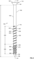
Figure 2 is another first side perspective view of the threaded fastener ofFigure 1 . -
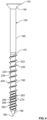
Figure 3 is a second side perspective view of the threaded fastener ofFigure 1 . -
Figure 4 is a third side perspective view of the threaded fastener ofFigure 1 . -
Figure 5 is a fourth side perspective view of the threaded fastener ofFigure 1 . -
Figure 6 is a top end view of the threaded fastener ofFigure 1 . -
Figure 7 is a bottom end view of the threaded fastener ofFigure 1 . -
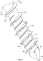
Figure 8 is an enlarged fragmentary perspective view of a part of the threaded fastener ofFigure 1 . -
Figure 9 is another enlarged fragmentary perspective view of a part of the threaded fastener ofFigure 1 . -
Figure 10 is a further enlarged fragmentary perspective view of a part of the threaded fastener ofFigure 1 . -
Figure 11 is a further enlarged fragmentary perspective view of a part of the threaded fastener ofFigure 1 . -
Figure 12 is a further enlarged fragmentary perspective view of a part of the threaded fastener ofFigure 1 . -
Figure 13 is an enlarged fragmentary sectional view of part of one of the threads of one example embodiment of a threaded fastener in accordance with the present disclosure. -
Figure 14 is an enlarged fragmentary sectional view of part of one of the threads of another example embodiment of a threaded fastener in accordance with the present disclosure. - While the systems, devices, and methods described herein may be embodied in various forms, the drawings show, and the specification describes certain exemplary and non-limiting embodiments. Not all components shown in the drawings and described in the specification may be required, and certain implementations may include additional, different, or fewer components. Variations in the arrangement and type of the components; the shapes, sizes, and materials of the components; and the manners of connections of the components may be made without departing from the spirit or scope of the claims. Unless otherwise indicated, any directions referred to in the specification reflect the orientations of the components shown in the corresponding drawings and do not limit the scope of the present disclosure. Further, terms that refer to mounting methods, such as mounted, connected, etc., are not intended to be limited to direct mounting methods but should be interpreted broadly to include indirect and operably mounted, connected, and like mounting methods. This specification is intended to be taken as a whole and interpreted in accordance with the principles of the present disclosure and as understood by one of ordinary skill in the art.
- Referring now to the Figures, a threaded
fastener 100 of one example embodiment of the present disclosure is shown inFigs. 1 ,2 ,3 ,4 ,5 ,6 ,7 ,8 ,9 ,10 ,11 , and12 . The threadedfastener 100 may sometimes be referred to herein as the "fastener" for brevity. Thefastener 100 is configured for use to secure an object to a substrate (such as but not limited to a concrete, masonry, and other cementitious substrate). - The threaded
fastener 100 includes ahead 110, ashank 150 connected to thehead 110, andthread formations shank 150. Thehead 110, theshank 150, and thethread formations fastener 100 of the present disclosure maximizes the material used for the formation of theshank 150 while still providing thehead 110 and thethread formations fastener 100. In other words, the present disclosure takes into account that for the formation of fastener, only a limited amount of material (such as steel) can be used to create the fastener, and specifically that during the formation process, only that limited amount of material can be used to form the head, the shank, and the thread formation(s) of the fastener. Thus, there is a trade off in the relative sizes and strengths of these components. For example, if a manufacturer wants a fastener that has four thread formations on the shank, the material for those four thread formations needs to come from the head or the shank, and thus the shank may need to be narrower. The present disclosure provides for a configuration of thefastener 100 including itshead 110, itsshank 150, and itsthread formations head 110 and thethread formations shank 150. - The
head 110 includes atop portion 120 spaced from theshank 150 and abottom portion 140 proximate theshank 150. Thetop portion 120 of thehead 110 defines a mechanicalengaging structure 122 that is engageable by an appropriate tool (not shown) for driving thefastener 100. In this example embodiment, the mechanicalengaging structure 122 includes defines a cross-shaped slot configured to receive a tool such as a Phillips head screwdriver. In other embodiments, the mechanical engaging structure defines a straight slot configured to receive a flathead screwdriver. In other embodiments, the mechanical engaging structure defines a hexagonal shaped cavity configured to receive an Allen wrench. In other embodiments, the mechanical engaging structure includes a hexagonal shaped bolt head engageable by an appropriate tool such as a socket or wrench. Any known or subsequently developed suitable mechanical engaging structure can be used as the engaging structure of thefastener 100 in accordance with the present disclosure. Thebottom portion 140 of thehead 110 includes a bottom surface (not separately labeled). The bottom surface generally faces away from thehead 110 and towards theshank 150. Thebottom portion 140 can include a plurality of ribs (not shown) extending from the bottom surface. In various such embodiments, the ribs can be arranged radially around a central axisA1 of thefastener 100 and thus the head 110 (which would extend through line A1-A1). Thehead 110 can be alternatively configured in accordance with the present disclosure. - The
shank 150 includes afirst shank portion 160, asecond shank portion 170, athird shank portion 180, and atip 190. Theshank 150 including thefirst shank portion 160, thesecond shank portion 170, thethird shank portion 180, and thetip 190 has a length L as shown inFigure 2 . - The
first shank portion 160 includes a first end (not labeled) connected to the head 110 (at a first end of the shank 150) and a second end (not labeled) connected to thesecond shank portion 170. Thefirst shank portion 160 has a constant or substantially constant outer diameter along the length of thefirst shank portion 160. In this embodiment, no thread formations extend from thefirst shank portion 160. - The
second shank portion 170 includes a first end (not labeled) connected to thefirst shank portion 160 and a second end (not labeled) connected to thethird shank portion 180. Thesecond portion 170 has a decreasing outer diameter from section thereof connected to thefirst shank portion 160 to section thereof connected to thethird shank portion 180. In this embodiment, only part of thefirst thread formation 220 extends from thesecond shank portion 170, and none of thesecond thread formation 260 extends from thesecond shank portion 170. - The
third shank portion 180 includes a first end (not labeled) connected to thesecond shank portion 170 and a second end (not labeled) connected to thetip 190. Thetip 190 includes a first end (not labeled) connected to thethird shank portion 180 and a pointedsecond end 196. Thethird shank portion 180 has a constant or substantially constant outer diameter along the length of thethird shank portion 180. In this embodiment, part of thefirst thread formation 220 extends from thethird shank portion 180, and thesecond thread formation 260 extends from the part of thethird shank portion 180. - The
tip 190 is pointed to aid in penetrating the substrate in which thefastener 100 is being driven. Thetip 190 can be alternatively configured in accordance with the present disclosure. Thetip 190 has a decreasing outer diameter from section thereof connected to thethird shank portion 180 to thetip 196 thereof. - The
shank 150 has a longitudinal axis A1 extending along the length L of theshank 150 from thehead 110 to the end of the pointedsecond end 196 of thetip 190. - In a first example embodiment that is a 3/16 inch fastener, the outer diameter of the
first shank portion 160 is 0.148 inches (3.7592 mm) and the outer diameter of thethird shank portion 180 is 0.133 inches (3.3528 mm). - In a second example embodiment that is a ¼ inch fastener, the outer diameter of the
first shank portion 160 is 0.189 inches (4.8006 mm) and the outer diameter of thethird shank portion 180 is 0.173 inches (4.3942 mm). - The
fastener 100 includes a firsthelical thread formation 220 connected to, extending along, and extending outwardly from thesecond portion 170 of theshank 150 and from thethird portion 180 of theshank 150. The firsthelical thread formation 220 includes a plurality of threads (not individually labeled) that span all or substantially all of the second andthird portions shank 150. - The first
helical thread formation 220 extends along the second andthird portions shank 150 in a helical or spiral formation in the direction of the longitudinal axis A1 of thefastener 100. - The first
helical thread formation 220 includes aroot 222 adjacent the outer surfaces (not labeled) of the second andthird portions shank 150. - The first
helical thread formation 220 includes acrest 230 opposite theroot 222 and spaced from the outer surfaces (not labeled) of the second andthird portions shank 150. - The first
helical thread formation 220 includes a trailingsurface 224 extending from theroot 222 to the crest 230 (at a 110 degree angle or approximately a 110 degree angle relative to the outer surface of thethird portion 180 of theshank 150 in this example embodiment). - The first
helical thread formation 220 includes a leadingsurface 226 extending from theroot 222 to the crest 230 (at a 110 degree angle or approximately a 110 degree angle relative to the outer surface of thethird portion 180 of theshank 150 in this example embodiment). - The leading
surface 224 and the trailingsurface 226 intersect at the crest 230 (at a 40 degree or approximately a 40 degree angle in this example embodiment). The crest can have a sharp edge or a somewhat flattened edge in various different embodiments. In this example embodiment, the leadingsurface 224 and the trailingsurface 226 thus define a 40 degree or approximately a 40 degree angle thread angle of the firsthelical thread formation 220. - These angles are applicable to both the example 3/16 inch and ¼ inch fasteners described herein.
- In this example configuration, less material needs to be used to form the first
helical thread formation 220 due to these relatively smaller angles (when compared to various commercially available fasteners). In this example configuration for thefastener 100, the material that could be used for the firsthelical thread formation 220 to make these angles larger is rather used for increasing the outer diameter of theshank 150 and thus making theshank 150 stronger. - In a first example embodiment that is a 3/16 inch fastener, the first
helical thread formation 220 has a 0.129 inch (3.2766 mm) pitch length. - In a second example embodiment that is a ¼ inch fastener, the first
helical thread formation 220 has a 0.133 inch (3.3782 mm) pitch length. - In a first example embodiment that is a 3/16 inch fastener, the first
helical thread formation 220 has an outer 0.208 inch (5.2832 mm) diameter. - In a second example embodiment that is a ¼ inch fastener, the first
helical thread formation 220 has an outer 0.250 inch (6.35 mm) diameter. - The outer diameter of the first
helical thread formation 220 is substantially constant along the length of thesecond portion 170 and thethird portion 180 of the shank 150 (except for the leading and terminating sections thereof that are downwardly tapered toward the shank 150). - As best shown in
Figures 2 ,8 and9 , the firsthelical thread formation 220 includes afirst thread portion 240 and asecond thread portion 250. - In this example embodiment, the
second thread portion 250 extends for the bottom three pitch lengths of the firsthelical thread formation 220 that are adjacent thetip 190. - The
first thread portion 240 extends for the rest of the pitch lengths of the firsthelical thread formation 220. - The
first thread portion 240 of the firsthelical thread formation 220 does not define any include any grooves. This reduces the torsional forces on thissecond portion 170 ofshank 150 and on the upper section of thethird portion 180 of theshank 150. - The
second thread portion 250 of the firsthelical thread formation 220 defines a plurality of spaced-apart grooves. As best shown inFigures 8 ,9 ,10 , and11 , in this example embodiment, the grooves are each partially defined by a first cutting surface (not labeled) and a second cutting surface (not labeled). It should be appreciated that the surfaces that define each groove can vary in accordance with the present disclosure. It should be appreciated that all of the grooves are identically configured in this example embodiment, but that one or more of the grooves may be alternatively configured. - The
fastener 100 also includes a secondhelical thread formation 260 connected to, extending along, and extending outwardly from a lower section of thethird portion 180 of theshank 150 adjacent thetip 190. The secondhelical thread formation 260 includes a plurality of threads (not individually labeled) that extend along a lower section of thethird portion 170 of theshank 150 in a helical or spiral formation in the direction of the longitudinal axis A1 of thefastener 100. - The second
helical thread formation 260 only spans the section of thethird portion 180 of theshank 150 that is adjacent to thetip 190. In this embodiment, the secondhelical thread formation 260 spans the same section or substantially the same section as thesecond thread portion 250 of the firsthelical thread formation 220. In this example configuration, less material needs to be used to form the secondhelical thread formation 260 due to its relatively short length. In this example configuration for thefastener 100, the material that could be used for the secondhelical thread formation 260 to span the second andthird sections shank 150 is rather used for increasing the outer diameter of theshank 150 and thus making theshank 150 stronger. - The threads of the second
helical thread formation 260 are positioned between the threads of the firsthelical thread formation 220. - The second
helical thread formation 260 includes aroot 262 adjacent the outer surface of thethird portion 180 of theshank 150. - The second
helical thread formation 260 includes acrest 270 opposite theroot 262 and spaced from the outer surface of thethird portion 180 of theshank 150. - The second
helical thread formation 260 includes a trailingsurface 264 extending from theroot 262 to the crest 270 (at a 110 degree angle or an approximately 110 degree angle relative to the outer surface of thethird portion 180 of theshank 150 in this example embodiment). - The second
helical thread formation 260 includes a leadingsurface 266 extending from theroot 262 to the crest 230 (at a 110 degree angle or an approximately 110 degree angle relative to the outer surface of thethird portion 180 of theshank 150 in this example embodiment). - The leading
surface 266 and the trailingsurface 264 intersect at the crest 270 (at a 40 degree angle or an approximately 40 degree angle in this example embodiment). The crest can have a sharp edge or a somewhat flattened edge in various different embodiments. The leadingsurface 266 and the trailingsurface 264 thus define a 40 degree or approximately 40 degree thread angle of the secondhelical thread formation 260 in this example embodiment. - These angles are applicable to both the example 3/16 inch and ¼ inch fasteners described herein.
- In a first example embodiment that is a 3/16 inch fastener, the second
helical thread formation 260 has a 0.129 inch (3.2766 mm) pitch length. - In a second example embodiment that is a ¼ inch fastener, the second
helical thread formation 260 has a 0.133 inch (3.3782 mm) pitch length. - In a first example embodiment that is a 3/16 inch fastener, the second
helical thread formation 260 has an outer 0.150 inch (3.81 mm) diameter. - In a second example embodiment that is a ¼ inch fastener, the second
helical thread formation 260 has an outer 0.200 inch (5.08 mm) diameter. - The outer diameter of the second
helical thread formation 260 is substantially constant along the length of thethird portion 180 of the shank 150 (except for the leading and terminating sections thereof which are downwardly tapered). - The second
helical thread formation 260 does not defines any grooves in this example embodiment. - In this example configuration, less material needs to be used to form the second
helical thread formation 260 due to these relatively smaller angles. In this example configuration for thefastener 100, the material that could be used for the secondhelical thread formation 260 to make these angles larger is rather used for increasing the outer diameter of theshank 150 and thus making theshank 150 stronger. - In this example embodiment, the
fastener 100 does not include any other helical thread formations connected to, extending along, and extending outwardly from shank. - Thus, in this example embodiment, the
fastener 100 includes ahead 110 and ashank 150 connected to thehead 110 at a first end of theshank 150. Theshank 150 includes afirst portion 160, asecond portion 170, athird portion 180, and atip 190 at an end of theshank 150 opposite thehead 110. Thefastener 100 includes a firsthelical thread formation 220 extending outwardly from the second andthird portions shank 150. Thefastener 110 includes a secondhelical thread formation 260 extending outwardly from a section of thethird portion 180 of theshank 150 that is adjacent to thetip 190. The firsthelical thread formation 220 defines grooves in the section of thethird portion 180 of theshank 150 that is adjacent to thetip 190. This configuration enables material that would otherwise be used for a second thread formation that extends the entire length of the first thread formation to be used for making theshank 150 have a relatively larger diameter and thus making theshank 150 stronger. - This configuration of the threaded
fastener 100 provides significant advantages in increasing the torsion strength of the fastener, and particularly of theshank 150, and thus reducing the likelihood of failure of theshank 150 and undesirable failures of thefastener 100. - It should be appreciated that the
fastener 100 is a right-handed threaded fastener, such that when it is turned in a clockwise fashion about axis A1 (when looking at thetop portion 120 of the head 110), thefastener 100 is tightened or driven, and when turned in a counter-clockwise fashion about axis A1 (when looking at thetop portion 120 of the head 110), thefastener 100 is loosened or backed out. It should be appreciated that the fastener could be formed as a left-handed threaded fastener, with the parts reversed. -
Figure 13 shows a sectional view of part of one of the threads of one example embodiment of a threaded fastener in accordance with the present disclosure. In this example embodiment,Figure 13 shows the cross-section of the relatively larger thread of the threaded fastener described above. - In this example, the first
helical thread formation 220A includes acrest 230A opposite the root and spaced from the outer surfaces (not labeled) of the shank (not labeled). - The first
helical thread formation 220A includes a trailing surface 224A extending from the root to thecrest 230A (at a 110 degree angle or approximately a 110 degree angle relative to the outer surface of the shank in this example embodiment). - The first
helical thread formation 220A includes aleading surface 226A extending from the root to thecrest 230A (at a 110 degree angle or approximately a 110 degree angle relative to the outer surface of the shank in this example embodiment). - The leading surface 224A and the trailing
surface 226A intersect at the crest 230a (at a 40 degree or approximately a 40 degree angle in this example embodiment). The crest can have a sharp edge or a somewhat flattened edge (such as shown) in various different embodiments. In this example embodiment, the leading surface 224A and the trailingsurface 226A thus define a 40 degree or approximately a 40 degree angle thread angle of the firsthelical thread formation 220A. -
Figure 14 shows a sectional view of part of one of the threads of another example embodiments of a threaded fastener in accordance with the present disclosure. In this example embodiment,Figure 14 shows the cross-section of the relatively larger thread of the threaded fastener described above. In this embodiment, the leading and trailing surfaces have alternative sections. - In this example, the first
helical thread formation 220B includes a crest (not labeled) opposite the root and spaced from the outer surfaces (not labeled) of the shank (not labeled). - The first
helical thread formation 220B includes a trailing surface having afirst section 222B, asecond section 231B connected to thefirst section 222B, and athird section 232B connected to thesecond section 231B. - The
first section 222B extends from the root toward the crest (at a 110 degree angle or approximately a 110 degree angle relative to the outer surface of the shank in this example embodiment). - The
second section 231B extends from thefirst section 222B toward the crest (at a 160 degree angle or approximately a 160 degree angle in this example embodiment). - The
third section 232B extends from thesecond section 231B toward the crest (at a 135 degree angle or approximately a 135 degree angle in this example embodiment). - The first
helical thread formation 220B includes a leading surface having afirst section 230B, asecond section 234B connected to thefirst section 230B, and athird section 233B connected to thesecond section 234B. - The
first section 230B extends from the root toward the crest (at a 110 degree angle or approximately a 110 degree angle relative to the outer surface of the shank in this example embodiment). - The
second section 234B extends from thefirst section 230B toward the crest (at a 160 degree angle or approximately a 160 degree angle in this example embodiment). - The
third section 233B extends from thesecond section 234B toward the crest (at a 135 degree angle or approximately a 135 degree angle in this example embodiment). - The
third section 233B of the leading surface and thethird section 232B of the trailing surface intersect at the crest (at a 90 degree or approximately a 90 degree angle in this example embodiment). The crest can have a sharp edge (such as shown) or a somewhat flattened edge in various different embodiments. - Generally, for fasteners, there is a trade off for sharp triangular thread cross section between thread angle and root diameter. In other words, as the material in the thread of the fastener is increased to maximize the holding power of the fastener (such as an increase in thread angle to 40 degrees, 50 degrees, or 60 degree), the material is taken from the root diameter, which can reduce torsional strength.
- This above described and illustrated example embodiment thread configuration optimizes material allocation to both the root diameter of the thread geometry and the tip of the thread geometry. This illustrated example embodiment employs an optimal amount of material in the tip of the thread while maintaining holding power and while keeping torsional strength at an optimal level. This illustrated embodiment also helps to reduce wear while cutting threads in a substrate. By moving material in this configuration to the tip of the thread, this configuration resists wear during the thread tapping operation (such as when using the self-tapping fastener in substrates like concrete).
- It will be understood that modifications and variations may be affected without departing from the scope of the novel concepts of the present invention, and it is understood that this application is to be limited only by the scope of the claims.
Certain embodiments of the invention are described in the following clauses: - Clause 1. A fastener comprising:
- a head;
- a shank connected to and extending from the head, the shank including:
- a first portion,
- a second portion connected to and extending from the first portion,
- a third portion connected to and extending from the second portion, and
- a tip connected to and extending from the third portion and at an end of the shank opposite the head;
- a first helical thread formation extending outwardly from the second and third portions of the shank,
- the first helical thread formation having a first thread portion and a second thread portion,
- the first thread portion of the first helical thread formation extending from the second portion of the shank,
- the first thread portion of the first helical thread formation extending from the third portion of the shank,
- the second thread portion of the first helical thread formation extending from the third portion of the shank,
- the second thread portion of the first helical thread formation defining grooves; and
- a second helical thread formation extending outwardly from the third portion of the shank.
- Clause 2. The fastener of clause 1, wherein the first thread portion of the first helical thread formation does not define any grooves.
- Clause 3. The fastener of clause 2, wherein the second thread portion of the first helical thread formation defines grooves.
- Clause 4. The fastener of clause 3, wherein only part of the second thread portion of the first helical thread formation defines grooves.
- Clause 5. The fastener of clause 4, wherein the part of the second thread portion of the first helical thread formation that is adjacent to the tip defines the grooves.
- Clause 6. The fastener of clause 5, wherein the second helical thread formation does not extend from the second portion of the shank.
- Clause 7. The fastener of clause 6, wherein the second helical thread formation does not extend from part of the third portion of the shank.
- Clause 8. The fastener of clause 6, wherein the second helical thread formation does not extend from part of the third portion of the shank that is adjacent to the second portion of the shank.
- Clause 9. The fastener of clause 1, wherein the second helical thread formation does not extend from part of the third portion of the shank.
- Clause 10. The fastener of clause 1, wherein the second helical thread formation does not extend from part of the third portion of the shank that is adjacent to the second portion of the shank.
- Clause 11. The fastener of clause 1, wherein the first portion of the shank has a greater outer diameter than the third portion of the shank.
- Clause 12. The fastener of clause 11, wherein the second portion of the shank is tapered from the first portion of the shank to the third portion of the shank.
- Clause 13. A fastener comprising:
- a head;
- a shank connected to and extending from the head, the shank including:
- a first portion,
- a second portion connected to and extending from the first portion,
- a third portion connected to and extending from the second portion, and
- a tip connected to and extending from the third portion and at an end of the shank opposite the head;
- a first helical thread formation extending outwardly from the second and third portions of the shank,
- the first helical thread formation having a first thread portion and a second thread portion,
- the first thread portion of the first helical thread formation extending from the second portion of the shank,
- the first thread portion of the first helical thread formation extending from the third portion of the shank,
- the first thread portion of the first helical thread formation not defining any grooves,
- the second thread portion of the first helical thread formation extending from the third portion of the shank,
- the second thread portion of the first helical thread formation defining grooves; and
- a second helical thread formation extending outwardly from the third portion of the shank,
- the second thread portion of the first helical thread formation defining grooves,
- the second helical thread formation not extending from the second portion of the shank,
- the second helical thread formation not extending from the third portion of the shank.
- Clause 14. The fastener of clause 13, wherein a part of the second thread portion of the first helical thread formation that is adjacent to the tip defines the grooves in the second thread portion of the first helical thread.
- Clause 15. The fastener of clause 11, wherein the first portion of the shank has a greater outer diameter than the third portion of the shank.
- Clause 16. The fastener of clause 15, wherein the second portion of the shank is tapered from the first portion of the shank to the third portion of the shank.
Claims (15)
- A fastener comprising:a head;a shank connected to and extending from the head, the shank including:a first portion,a second portion connected to and extending from the first portion,a third portion connected to and extending from the second portion, anda tip connected to and extending from the third portion and at an end of the shank opposite the head;a first helical thread formation extending outwardly from the second and third portions of the shank,the first helical thread formation having a first thread portion and a second thread portion,the first thread portion of the first helical thread formation extending from the second portion of the shank,the first thread portion of the first helical thread formation extending from the third portion of the shank,the second thread portion of the first helical thread formation extending from the third portion of the shank,the second thread portion of the first helical thread formation defining grooves; anda second helical thread formation extending outwardly from the third portion of the shank.
- The fastener of claim 1, wherein the first thread portion of the first helical thread formation does not define any grooves.
- The fastener of claim 2, wherein the second thread portion of the first helical thread formation defines grooves.
- The fastener of claim 3, wherein only part of the second thread portion of the first helical thread formation defines grooves.
- The fastener of claim 4, wherein the part of the second thread portion of the first helical thread formation that is adjacent to the tip defines the grooves.
- The fastener of claim 5, wherein the second helical thread formation does not extend from the second portion of the shank.
- The fastener of claim 6, wherein the second helical thread formation does not extend from part of the third portion of the shank.
- The fastener of claim 6, wherein the second helical thread formation does not extend from part of the third portion of the shank that is adjacent to the second portion of the shank.
- The fastener of claim 1, wherein the second helical thread formation does not extend from part of the third portion of the shank.
- The fastener of claim 1, wherein the second helical thread formation does not extend from part of the third portion of the shank that is adjacent to the second portion of the shank.
- The fastener of claim 1, wherein the first portion of the shank has a greater outer diameter than the third portion of the shank.
- The fastener of claim 11, wherein the second portion of the shank is tapered from the first portion of the shank to the third portion of the shank.
- A fastener comprising:a head;a shank connected to and extending from the head, the shank including:a first portion,a second portion connected to and extending from the first portion,a third portion connected to and extending from the second portion, anda tip connected to and extending from the third portion and at an end of the shank opposite the head;a first helical thread formation extending outwardly from the second and third portions of the shank,the first helical thread formation having a first thread portion and a second thread portion,the first thread portion of the first helical thread formation extending from the second portion of the shank,the first thread portion of the first helical thread formation extending from the third portion of the shank,the first thread portion of the first helical thread formation not defining any grooves,the second thread portion of the first helical thread formation extending from the third portion of the shank,the second thread portion of the first helical thread formation defining grooves; anda second helical thread formation extending outwardly from the third portion of the shank,the second thread portion of the first helical thread formation defining grooves,the second helical thread formation not extending from the second portion of the shank,the second helical thread formation not extending from the third portion of the shank.
- The fastener of claim 13, wherein a part of the second thread portion of the first helical thread formation that is adjacent to the tip defines the grooves in the second thread portion of the first helical thread.
- The fastener of claim 11, wherein the first portion of the shank has a greater outer diameter than the third portion of the shank, and optionally wherein the second portion of the shank is tapered from the first portion of the shank to the third portion of the shank.
Applications Claiming Priority (2)
| Application Number | Priority Date | Filing Date | Title |
|---|---|---|---|
| US202363513629P | 2023-07-14 | 2023-07-14 | |
| US18/760,188 US20250020154A1 (en) | 2023-07-14 | 2024-07-01 | Threaded fasteners |
Publications (1)
| Publication Number | Publication Date |
|---|---|
| EP4491892A1 true EP4491892A1 (en) | 2025-01-15 |
Family
ID=91899158
Family Applications (1)
| Application Number | Title | Priority Date | Filing Date |
|---|---|---|---|
| EP24187500.4A Pending EP4491892A1 (en) | 2023-07-14 | 2024-07-09 | Threaded fasteners |
Country Status (4)
| Country | Link |
|---|---|
| US (1) | US20250020154A1 (en) |
| EP (1) | EP4491892A1 (en) |
| AU (1) | AU2024204655A1 (en) |
| CA (1) | CA3246009A1 (en) |
Families Citing this family (4)
| Publication number | Priority date | Publication date | Assignee | Title |
|---|---|---|---|---|
| CA203180S (en) * | 2020-11-26 | 2022-11-10 | Illinois Tool Works | Fastener |
| CA221032S (en) * | 2022-11-15 | 2024-08-02 | Howmet Aerospace Inc | Fastener |
| USD1116792S1 (en) * | 2023-07-14 | 2026-03-10 | Illinois Tool Works Inc. | Threaded fastener |
| USD1075491S1 (en) * | 2023-08-09 | 2025-05-20 | Integral Building Products Incorporation | Screw |
Citations (2)
| Publication number | Priority date | Publication date | Assignee | Title |
|---|---|---|---|---|
| US20180209465A1 (en) * | 2017-01-25 | 2018-07-26 | Kwantex Research Inc. | Screw |
| US20230067592A1 (en) * | 2020-02-11 | 2023-03-02 | B.M.B. Investments Pty Ltd | A Multipurpose Screw |
-
2024
- 2024-07-01 US US18/760,188 patent/US20250020154A1/en active Pending
- 2024-07-03 CA CA3246009A patent/CA3246009A1/en active Pending
- 2024-07-04 AU AU2024204655A patent/AU2024204655A1/en active Pending
- 2024-07-09 EP EP24187500.4A patent/EP4491892A1/en active Pending
Patent Citations (2)
| Publication number | Priority date | Publication date | Assignee | Title |
|---|---|---|---|---|
| US20180209465A1 (en) * | 2017-01-25 | 2018-07-26 | Kwantex Research Inc. | Screw |
| US20230067592A1 (en) * | 2020-02-11 | 2023-03-02 | B.M.B. Investments Pty Ltd | A Multipurpose Screw |
Also Published As
| Publication number | Publication date |
|---|---|
| US20250020154A1 (en) | 2025-01-16 |
| AU2024204655A1 (en) | 2025-01-30 |
| CA3246009A1 (en) | 2025-06-06 |
Similar Documents
| Publication | Publication Date | Title |
|---|---|---|
| US20250020154A1 (en) | Threaded fasteners | |
| EP1371862B1 (en) | Self-drilling fastener | |
| US11578747B2 (en) | Threaded fastener | |
| EP2310695B1 (en) | Self-drilling anchor | |
| US5516248A (en) | Low torque wood screw | |
| EP1522744B1 (en) | Self-drilling anchor | |
| US12180989B2 (en) | Threaded fastener | |
| EP3399200B1 (en) | Screw for thin iron sheets | |
| EP3737869B1 (en) | Self-drilling anchor assembly | |
| EP3354912B1 (en) | Screw | |
| CN102369362A (en) | Self-tapping thread forming screw and corresponding thread roll die | |
| US20060018730A1 (en) | Drywall fastener | |
| EP4686842A1 (en) | Self-drilling self-tapping fastener | |
| EP2069645B1 (en) | Drywall fastener | |
| AU2007200511B2 (en) | Self-drilling anchor |
Legal Events
| Date | Code | Title | Description |
|---|---|---|---|
| PUAI | Public reference made under article 153(3) epc to a published international application that has entered the european phase |
Free format text: ORIGINAL CODE: 0009012 |
|
| STAA | Information on the status of an ep patent application or granted ep patent |
Free format text: STATUS: THE APPLICATION HAS BEEN PUBLISHED |
|
| AK | Designated contracting states |
Kind code of ref document: A1 Designated state(s): AL AT BE BG CH CY CZ DE DK EE ES FI FR GB GR HR HU IE IS IT LI LT LU LV MC ME MK MT NL NO PL PT RO RS SE SI SK SM TR |
|
| STAA | Information on the status of an ep patent application or granted ep patent |
Free format text: STATUS: REQUEST FOR EXAMINATION WAS MADE |
|
| 17P | Request for examination filed |
Effective date: 20250710 |
|
| GRAP | Despatch of communication of intention to grant a patent |
Free format text: ORIGINAL CODE: EPIDOSNIGR1 |
|
| STAA | Information on the status of an ep patent application or granted ep patent |
Free format text: STATUS: GRANT OF PATENT IS INTENDED |
|
| RIC1 | Information provided on ipc code assigned before grant |
Ipc: F16B 25/00 20060101AFI20260130BHEP Ipc: F16B 25/10 20060101ALN20260130BHEP |
|
| INTG | Intention to grant announced |
Effective date: 20260211 |
|
| P01 | Opt-out of the competence of the unified patent court (upc) registered |
Free format text: CASE NUMBER: UPC_APP_0011232_4491892/2026 Effective date: 20260327 |
|
| GRAS | Grant fee paid |
Free format text: ORIGINAL CODE: EPIDOSNIGR3 |
|
| GRAA | (expected) grant |
Free format text: ORIGINAL CODE: 0009210 |
|
| STAA | Information on the status of an ep patent application or granted ep patent |
Free format text: STATUS: THE PATENT HAS BEEN GRANTED |