EP4491864A1 - Check valve for a crank case ventilation system - Google Patents
Check valve for a crank case ventilation system Download PDFInfo
- Publication number
- EP4491864A1 EP4491864A1 EP23315281.8A EP23315281A EP4491864A1 EP 4491864 A1 EP4491864 A1 EP 4491864A1 EP 23315281 A EP23315281 A EP 23315281A EP 4491864 A1 EP4491864 A1 EP 4491864A1
- Authority
- EP
- European Patent Office
- Prior art keywords
- housing
- check valve
- plunger
- support body
- valve
- Prior art date
- Legal status (The legal status is an assumption and is not a legal conclusion. Google has not performed a legal analysis and makes no representation as to the accuracy of the status listed.)
- Withdrawn
Links
Images


Classifications
-
- F—MECHANICAL ENGINEERING; LIGHTING; HEATING; WEAPONS; BLASTING
- F02—COMBUSTION ENGINES; HOT-GAS OR COMBUSTION-PRODUCT ENGINE PLANTS
- F02M—SUPPLYING COMBUSTION ENGINES IN GENERAL WITH COMBUSTIBLE MIXTURES OR CONSTITUENTS THEREOF
- F02M35/00—Combustion-air cleaners, air intakes, intake silencers, or induction systems specially adapted for, or arranged on, internal-combustion engines
- F02M35/10—Air intakes; Induction systems
- F02M35/10209—Fluid connections to the air intake system; their arrangement of pipes, valves or the like
- F02M35/10222—Exhaust gas recirculation [EGR]; Positive crankcase ventilation [PCV]; Additional air admission, lubricant or fuel vapour admission
-
- F—MECHANICAL ENGINEERING; LIGHTING; HEATING; WEAPONS; BLASTING
- F01—MACHINES OR ENGINES IN GENERAL; ENGINE PLANTS IN GENERAL; STEAM ENGINES
- F01M—LUBRICATING OF MACHINES OR ENGINES IN GENERAL; LUBRICATING INTERNAL COMBUSTION ENGINES; CRANKCASE VENTILATING
- F01M13/00—Crankcase ventilating or breathing
- F01M13/0011—Breather valves
-
- F—MECHANICAL ENGINEERING; LIGHTING; HEATING; WEAPONS; BLASTING
- F16—ENGINEERING ELEMENTS AND UNITS; GENERAL MEASURES FOR PRODUCING AND MAINTAINING EFFECTIVE FUNCTIONING OF MACHINES OR INSTALLATIONS; THERMAL INSULATION IN GENERAL
- F16K—VALVES; TAPS; COCKS; ACTUATING-FLOATS; DEVICES FOR VENTING OR AERATING
- F16K15/00—Check valves
- F16K15/02—Check valves with guided rigid valve members
- F16K15/06—Check valves with guided rigid valve members with guided stems
- F16K15/063—Check valves with guided rigid valve members with guided stems the valve being loaded by a spring
-
- F—MECHANICAL ENGINEERING; LIGHTING; HEATING; WEAPONS; BLASTING
- F16—ENGINEERING ELEMENTS AND UNITS; GENERAL MEASURES FOR PRODUCING AND MAINTAINING EFFECTIVE FUNCTIONING OF MACHINES OR INSTALLATIONS; THERMAL INSULATION IN GENERAL
- F16K—VALVES; TAPS; COCKS; ACTUATING-FLOATS; DEVICES FOR VENTING OR AERATING
- F16K27/00—Construction of housing; Use of materials therefor
- F16K27/02—Construction of housing; Use of materials therefor of lift valves
- F16K27/0209—Check valves or pivoted valves
-
- F—MECHANICAL ENGINEERING; LIGHTING; HEATING; WEAPONS; BLASTING
- F01—MACHINES OR ENGINES IN GENERAL; ENGINE PLANTS IN GENERAL; STEAM ENGINES
- F01M—LUBRICATING OF MACHINES OR ENGINES IN GENERAL; LUBRICATING INTERNAL COMBUSTION ENGINES; CRANKCASE VENTILATING
- F01M13/00—Crankcase ventilating or breathing
- F01M13/04—Crankcase ventilating or breathing having means for purifying air before leaving crankcase, e.g. removing oil
- F01M2013/0488—Crankcase ventilating or breathing having means for purifying air before leaving crankcase, e.g. removing oil with oil trap in the return conduit to the crankcase
- F01M2013/0494—Crankcase ventilating or breathing having means for purifying air before leaving crankcase, e.g. removing oil with oil trap in the return conduit to the crankcase using check valves
Definitions
- the present invention refers to a check valve, the check valve comprising
- Crank case ventilation systems are also generally known.
- DE 10 2011 118 790 B4 discloses a crank case ventilation system for an internal combustion engine with a breather line connecting the crank case of the internal combustion engine with an intake tract of the internal combustion engine. The use of a check valve is not described in DE 10 2011 118 790 B4 .
- Crank case ventilation systems are used to feed gases from the crank case into an air intake system of a combustion engine.
- a float operated fuel vapor vent valve which has a body structure with an annular mounting flange formed of material weldable to a fuel tank and the flange is spin welded to the tank.
- a float is biased upwardly by a spring with one end registered against the lower end of the float and the opposite end of the spring registered against an end cap or closure member secured in the lower end of a float chamber.
- the float has at least one and preferably a plurality of oppositely disposed engagement surfaces in the form of longitudinal groves formed therein; and the wall of the float chamber has correspondingly configured engagement surfaces in the form of projections provided thereon which slidably engage the grooves respectively.
- a check valve for a crank case ventilation system comprises
- crank case ventilation systems check valves are used to feed gases from the crank case into an air intake system of a combustion engine, when the pressure in the crank case exceeds the opening pressure of the check valve. Furthermore, using check valves, which are closed by default, an automatic detection of open lines, e.g. due to loose pipes or hoses, in such crank case ventilation systems is possible.
- the plunger is movable inside the housing in order to close or open the check valve.
- the fluid passage is closed by plunger being pressed against the valve seat because of the spring force.
- the spring biases the plunger into a closed position. Motion of the plunger away from the valve seat enables a fluid flow in a direction of allowed fluid flow. Fluid flow in the reverse direction is prohibited by the plunger sealingly abutting the valve seat.
- the check valve may be referred to as a nonreturn check valve.
- the support body serves as a support for the spring. Furthermore, the support body may contribute to guide the plunger in radial direction during its axial (longitudinal) motion.
- the support body is snap fitted to the housing in a fixed angular position with respect to the longitudinal axis.
- the snap fit of the support body and the housing significantly simplifies assembly of the check valve.
- the spring and the plunger can be arranged relative to one another and either be inserted into the housing or they are positioned at the support body. To finish assembly of the check valve, the support body is pressed into the housing, whereby the snap connection is automatically established.
- the snap connection between the support body and the housing is established such that the support body and the housing are non-rotatable against each other with respect to the longitudinal axis.
- the support body and the housing cannot rotate around the longitudinal axis relative to one another.
- This facilitates mounting the check valve to another component of the crank case ventilation system, e.g. a heater pipe, in particular by rotational welding (spin welding).
- Rotational welding is efficient and fast to execute and ensures a fluid tight connection.
- the support body rotates together with the housing. Damage to the components of the check valve is thereby prevented.
- the support body which rotates around the longitudinal axis with the housing during rotational welding, protects in particular the spring and the plunger.
- the support body decouples the spring and the plunger from the relative movement to the other component (e.g. heater pipe) during welding. Since no anti-rotation measures between the housing and the plunger are required, no additional friction or higher freezing risk results later valve operation.
- the snap fitted support body is held at the housing in a completely fixed position. I.e. the support body cannot move in any direction, neither by translation nor by rotational movement.
- the support body has latching hooks, which protrude into the housing and engage into grooves of the housing.
- the latching hooks can also be referred to as tongues, which are provided with a hook protrusion.
- the grooves are generally formed as recesses in an interior wall of the housing. By engagement of the latching hooks into the recesses, a fixed rotational position is ensured.
- the latching hooks and the grooves generally extend in axial (longitudinal) direction. Typically, two, three or four grooves and latching hooks are provided, respectively. Equal spacing of the grooves and latching hooks around the longitudinal axis is preferred.
- the grooves extend beyond the latching hooks in longitudinal direction towards the valve seat. This means that the grooves are longer in axial direction than needed for accommodation of the latching hooks.
- the free sections of the grooves increase a cross section for fluid flow when the valve is open.
- a flow resistance of the check valve can be adapted as required. A particularly low flow resistance can be obtained.
- the grooves may each have an indentation in radial direction.
- a hook protrusion of the latching hooks engages into the indentations. This design contributes to keep the latching hooks close to the interior wall of the housing, in order not to hinder fluid flow or motion of the plunger.
- the plunger may comprise a shaft and a seal head.
- the seal head is adapted to cover a valve opening at the valve seat of the housing. This design requires little material and allows for improved guidance of the valve components relative to each other.
- the spring may be arranged around the shaft.
- a gasket is overmolded to the seal head. The gasket ensures tight closure of the valve. Overmolding is an efficient manufacturing technique and avoids the gasket from being lost or forgotten to include during assembly.
- the support body has a guidance hole, through which the shaft of the plunger extends. This further improves alignment of the plunger in the housing.
- the seal head may have radially outward protruding ribs for radial guidance of the seal head against the housing during axial motion of the plunger.
- the housing has radially inward protruding ribs for radial guidance of the seal head during axial motion of the plunger.
- This design facilitates manufacturing and mounting of the plunger.
- An outer radius of the seal head may correspond to a distance of the ribs from the longitudinal axis.
- the ribs of the housing protrude from an interior wall thereof. The ribs may extend between the latching hooks of the support body.
- the support body may have at least one stopper for the plunger, which protrudes into the housing. Upon opening of the check valve, the stoppers delimit axial motion of the plunger.
- the stoppers may be arranged for abutment of the seal head of the plunger.
- the stopper may be formed separately from the latching hooks of the support body. In particular, the stopper protrudes further towards the valve seat than the latching hooks.
- the stopper protrudes further radially inward than the ribs for radial guidance of the seal head. This ensures that the seal head hits the stoppers at the predetermined axial (longitudinal) position.
- the ribs may engage between the stoppers and the latching hooks.
- the housing may have a rotational welding protrusion.
- the rotational welding protrusion is designed to deform during rotational welding of the housing to another component of the crank case ventilation system, e.g. a heater pipe.
- the rotational welding protrusion may be formed as an axially protruding collar.
- the rotational welding protrusion and the support body are arranged at the same axial end of the housing. This is favorable with respect to operational conditions of the check valve, in particular when a heater pipe is welded to the housing.
- the invention also refers to a valve assembly comprising a check valve as described above and a pipe piece, wherein the housing of the check valve and the pipe piece are permanently bonded to one another.
- the pipe piece as part of the crank case ventilation systems facilitates integration of the check valve. Dismounting of the permanent bond requires destruction of the valve assembly.
- the housing and the pipe piece are bonded by rotational welding.
- Rotational welding is efficient and fast to execute and ensures a fluid tight connection.
- a heating element may be attached to the pipe piece.
- the pipe piece is a heater pipe.
- Use of the heating element to heat gas inside the valve assembly may avoid the check valve from freezing. In particular, it may be avoided that the seal head or gasket freezes to the valve seat.
- the pipe piece has a socket for electric power supply to the heating element. This facilitates operation of the heater element.
- the invention refers to a method for manufacturing a valve assembly as described above.
- the method comprises:
- Providing the check valve may comprise:
- the spring may be arranged around a shaft of the plunger. This method allows for efficient manufacturing of the valve assembly with a fluid tight connection of the housing to the pipe piece.
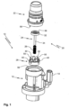
- Figure 1 shows a valve assembly 10 in an exploded view.
- Figure 2 a longitudinal section through the mounted valve assembly is shown.
- the valve assembly 10 comprises a pipe piece 12 , which is a heater pipe in the present embodiment.
- the pipe piece 12 has a socket 14 (see Figure 1 ) for supplying electric power to a heating element 16 (see Figure 2 ), which is located inside heater pipe 12.
- the valve assembly 10 further comprises a check valve 20.
- the check valve conprises a housing 22, a plunger 24, a spring 26 and a support body 28.
- the suppport body 28 typically has flow openings 29, cf. Figure 2 .
- a valve seat 30 is formed inside the housing 22.
- the valve seat 30 surrounds a valve opening 31.
- the plunger 24 is partially accomodated inside the housing 22. In the closed position, the plunger 24 covers the valve opening 31 by abutment against the valve seat 30.
- the plunger 24 has a seal head 32 and a shaft 34.
- a gasket 36 here a axially sealing gasket, is attached to the seal head 32.
- the seal head 32 with gasket 34 sealingly abuts the valve seat 30.
- the support body 28 is held at the housing 22 by a snap fit.
- the spring 26 is compressed between the seal head 32 and the support body 28.
- the spring 26 presses the plunger 24 against the valve seat 30.
- the plunger 24 can move along a longitudional axis 38 in order to open the check valve 20.
- the snap fit secures the support body 28 to the housing 22 in a fixed angular position with respect to the longiutidinal axis 38.
- the support body 28 has axially extending latching hooks 40 (see Figures 1 and 2 ).
- latching hooks 40 are provided.
- a hook protrusion 42 which points radially outwardly, is formed at the free end of each latching hook 40.
- the housing has axially extending grooves 44 , see in particular Figure 2 , which are depressions or recesses in an interior wall 45 of the housing 22.
- three grooves 44 are provided.
- the grooves 44 each extend from an end of the housing 22, at which end the support body 28 is to be received, towards the valve seat 30.
- the grooves 44 are each provided with an indentation 46 which forms a shoulder 48.
- each latching hook 40 is received in one of the grooves 44.
- the hook protrusions 42 engage into the indentations 46 and behind the shoulders 48.
- the support body is secured to the housing in axial direction (in paricular by engagement of the hook protrusions 42 behind the shoulder 48) and in rotational direction (by engagement of the latching hooks 40 into the grooves 44, which are just wide enough in circumferential direction to receive the latching hooks 40).
- the spring 26 is arranged around the shaft 34 of the plunger 24.
- the plunger 24 with the spring 26 are inserted into the housing 22.
- the shaft 34 of the plunger 24 is introduced into a guidance hole 54 of the support body 28.
- the support body 28 is pressed into the housing 22 so that the latching hooks snap into the grooves 44.
- the grooves 44 extend towards the valve seat 30 significantly farter as required to accommodate the latching hooks 40.
- the grooves 44 may extend at least 1 cm, preferably at least 1.5 cm, beyond the latching hooks 40 in axial direction.
- the grooves 44 may extend all the way to the valve seat 30 or they may terminate at an axial distance, of e.g. between 3 mm to 1 cm, from the valve seat 30.
- the open sections of the grooves 44 allow for low resistance gas flow when the check valve 20 is in the open state (plunger 24 liftet from valve seat 30 against the action of spring 26, not depicted).
- the support body comprises stoppers 50, which delimit the opening movement of the plunger 24.
- the stoppers 50 extend in axial direction at least as far as the latching hooks 40, in particular at least 1 mm farther.
- the housing 22 has ribs 52, which protrude radially inwardly from the interor wall 45, see Figure 2 and Figure 3 .
- ribs 52 are provided.
- the ribs 52 extend from the valve seat 30 towards the support body in axial direction, cf. Figure 2 .
- the stoppers 50 protrude furhter towars the longitudinal axis 38 than the ribs 52, in paricular by at least 1 mm.
- the ribs 52 engage between the latching hooks 40 and the stoppers 50 of the support body 28.
- the ribs 52 provide radial guidance to the plunger 24 by abutment against the outer perimeter of the seal head 32.
- the support body 28 has a guidance hole 54, which is concentric to the longitudinal axis 38.
- the shaft 34 of the plunger 24 is received in the guidance hole 54.
- the shaft 34 may extend completely through the guidance hole 54 in axial direction.
- the inner diameter of the guidance hole 54 is slightly wider than the outer diameter of the shaft 34, for instance by at least 0.1 mm and/or at most 0.5 mm.
- the guidance hole 54 provides radial guidance to the plunger 24 at the shaft 34. With the guidance hole 54 and the ribs 52, a radial position of the plunger 24 is defined in two axially spaced apart locations.
- the housing 22 of the check valve 20 is fixed to the pipe piece 12 by rotational welding, cf. step 106 in Figure 4 .
- the housing 22 has a rotational welding protrusion 56, here designed as an annular collar, cf. Figures 1 and 2 .
- the rotational welding protrusion 56 is provided at the same axial end of the housing 22 as is the support body 28.
- the rotational welding protrusion 56 surrounds the support body 28 on the radially outside.
- the rotational welding protrusion 56 may or may not protrude (cf. Figure 2 ) beyond the support body 28 in axial direction.
- the support body 28 and the shaft 34 of the plunger 24 are partially received inside the pipe piece 12.
- the hpusing 22 with the rotational welding protrusion 56 is rotated around the longitudinal axis 38 relative to the pipe piece 12 and pressed against a rotational welding flange 58 of the pipe piece 12, thus generating heat.
- the support body 28 rotates together with the housing 22 and protects the plunger 24 and the spring 26.
- the rotational welding flange 58 and the rotational welding protrusion 56 are compressed in axial direction and establish a permanent, gas thight bond upon cooling, after the rotation has been stopped.
- the invention relates to a non-return check valve for crank case ventilation.
- a support body is clipped into a housing in a fixed rotational position. Thereto, latching hooks of the support body may engage into axially extending grooves of the housing.
- a plunger is urged to close a passage in the housing by a spring, which is axially supported on the support body.
Landscapes
- Engineering & Computer Science (AREA)
- General Engineering & Computer Science (AREA)
- Mechanical Engineering (AREA)
- Chemical & Material Sciences (AREA)
- Combustion & Propulsion (AREA)
- Check Valves (AREA)
Abstract
The invention refers to a non-return check valve for crank case ventilation. A support body is clipped into a housing in a fixed rotational position. Thereto, latching hooks of the support body may engage into axially extending grooves of the housing. A plunger is urged to close a passage in the housing by a spring, which is axially supported on the support body..
Description
- The present invention refers to a check valve, the check valve comprising
- a housing, having a valve seat;
- a plunger, at least partially received inside the housing and movable along a longitudinal axis inside the housing;
- a spring, biasing the plunger against the valve seat of the housing; and
- a support body, against which the spring rests.
- Check valves of this type are generally known.
- Crank case ventilation systems are also generally known. E.g.
DE 10 2011 118 790 B4 discloses a crank case ventilation system for an internal combustion engine with a breather line connecting the crank case of the internal combustion engine with an intake tract of the internal combustion engine. The use of a check valve is not described inDE 10 2011 118 790 B4 - Crank case ventilation systems are used to feed gases from the crank case into an air intake system of a combustion engine.
- From
US 2005/0055817 A1 a float operated fuel vapor vent valve is known, which has a body structure with an annular mounting flange formed of material weldable to a fuel tank and the flange is spin welded to the tank. A float is biased upwardly by a spring with one end registered against the lower end of the float and the opposite end of the spring registered against an end cap or closure member secured in the lower end of a float chamber. When the fuel level in the tank rises to a certain level, upward movement of the float causes a valve member to close against a valve seat. The float has at least one and preferably a plurality of oppositely disposed engagement surfaces in the form of longitudinal groves formed therein; and the wall of the float chamber has correspondingly configured engagement surfaces in the form of projections provided thereon which slidably engage the grooves respectively. Upon spin welding of the body flange onto the fuel tank the sliding engagement of the projections with the grooves prevents relative rotation of the float with respect to the body. - It is an object of the invention to improve assembly of crank case ventilation systems and in particular check valves thereof.
- This is achieved by a check valve according to claim 1, a valve assembly according to
claim 12 and a manufacturing method according to claim 15. Advantageous embodiments are given in the subclaims and the description. - In accordance with the invention, a check valve for a crank case ventilation system is provided. The check valve comprises
- a housing, having a valve seat;
- a plunger, at least partially received inside the housing and movable along a longitudinal axis;
- a spring, biasing the plunger against the valve seat of the housing; and
- a support body, against which the spring rests.
- In crank case ventilation systems, check valves are used to feed gases from the crank case into an air intake system of a combustion engine, when the pressure in the crank case exceeds the opening pressure of the check valve. Furthermore, using check valves, which are closed by default, an automatic detection of open lines, e.g. due to loose pipes or hoses, in such crank case ventilation systems is possible.
- The plunger is movable inside the housing in order to close or open the check valve. By default, the fluid passage is closed by plunger being pressed against the valve seat because of the spring force. In other words, the spring biases the plunger into a closed position. Motion of the plunger away from the valve seat enables a fluid flow in a direction of allowed fluid flow. Fluid flow in the reverse direction is prohibited by the plunger sealingly abutting the valve seat. The check valve may be referred to as a nonreturn check valve.
- The support body serves as a support for the spring. Furthermore, the support body may contribute to guide the plunger in radial direction during its axial (longitudinal) motion. By amending the design of the support body, flow characteristics of the check valve can easily be adjusted without the need of design amendments to the other components of the check valve.
- According to the invention, the support body is snap fitted to the housing in a fixed angular position with respect to the longitudinal axis. The snap fit of the support body and the housing significantly simplifies assembly of the check valve. The spring and the plunger can be arranged relative to one another and either be inserted into the housing or they are positioned at the support body. To finish assembly of the check valve, the support body is pressed into the housing, whereby the snap connection is automatically established.
- The snap connection between the support body and the housing is established such that the support body and the housing are non-rotatable against each other with respect to the longitudinal axis. In other words, the support body and the housing cannot rotate around the longitudinal axis relative to one another. This facilitates mounting the check valve to another component of the crank case ventilation system, e.g. a heater pipe, in particular by rotational welding (spin welding). Rotational welding is efficient and fast to execute and ensures a fluid tight connection. During rotational welding, the support body rotates together with the housing. Damage to the components of the check valve is thereby prevented. The support body, which rotates around the longitudinal axis with the housing during rotational welding, protects in particular the spring and the plunger. In other words, the support body decouples the spring and the plunger from the relative movement to the other component (e.g. heater pipe) during welding. Since no anti-rotation measures between the housing and the plunger are required, no additional friction or higher freezing risk results later valve operation.
- Preferably, the snap fitted support body is held at the housing in a completely fixed position. I.e. the support body cannot move in any direction, neither by translation nor by rotational movement.
- Directional references such as radial, axial or longitudinal generally refer to the longitudinal axis, if not stated otherwise.
- Preferably, the support body has latching hooks, which protrude into the housing and engage into grooves of the housing. The latching hooks can also be referred to as tongues, which are provided with a hook protrusion. The grooves are generally formed as recesses in an interior wall of the housing. By engagement of the latching hooks into the recesses, a fixed rotational position is ensured. The latching hooks and the grooves generally extend in axial (longitudinal) direction. Typically, two, three or four grooves and latching hooks are provided, respectively. Equal spacing of the grooves and latching hooks around the longitudinal axis is preferred.
- Particularly preferably, the grooves extend beyond the latching hooks in longitudinal direction towards the valve seat. This means that the grooves are longer in axial direction than needed for accommodation of the latching hooks. The free sections of the grooves increase a cross section for fluid flow when the valve is open. In particular, by appropriately choosing the dimensions (length and/or width) of the grooves a flow resistance of the check valve can be adapted as required. A particularly low flow resistance can be obtained.
- The grooves may each have an indentation in radial direction. A hook protrusion of the latching hooks engages into the indentations. This design contributes to keep the latching hooks close to the interior wall of the housing, in order not to hinder fluid flow or motion of the plunger.
- The plunger may comprise a shaft and a seal head. The seal head is adapted to cover a valve opening at the valve seat of the housing. This design requires little material and allows for improved guidance of the valve components relative to each other. The spring may be arranged around the shaft. Preferably, a gasket is overmolded to the seal head. The gasket ensures tight closure of the valve. Overmolding is an efficient manufacturing technique and avoids the gasket from being lost or forgotten to include during assembly.
- Advantageously, the support body has a guidance hole, through which the shaft of the plunger extends. This further improves alignment of the plunger in the housing.
- In one embodiment, the seal head may have radially outward protruding ribs for radial guidance of the seal head against the housing during axial motion of the plunger.
- In a preferred embodiment, the housing has radially inward protruding ribs for radial guidance of the seal head during axial motion of the plunger. This design facilitates manufacturing and mounting of the plunger. An outer radius of the seal head may correspond to a distance of the ribs from the longitudinal axis. The ribs of the housing protrude from an interior wall thereof. The ribs may extend between the latching hooks of the support body.
- The support body may have at least one stopper for the plunger, which protrudes into the housing. Upon opening of the check valve, the stoppers delimit axial motion of the plunger. In particular, the stoppers may be arranged for abutment of the seal head of the plunger.
- The stopper may be formed separately from the latching hooks of the support body. In particular, the stopper protrudes further towards the valve seat than the latching hooks.
- Preferably, the stopper protrudes further radially inward than the ribs for radial guidance of the seal head. This ensures that the seal head hits the stoppers at the predetermined axial (longitudinal) position. The ribs may engage between the stoppers and the latching hooks.
- The housing may have a rotational welding protrusion. The rotational welding protrusion is designed to deform during rotational welding of the housing to another component of the crank case ventilation system, e.g. a heater pipe. The rotational welding protrusion may be formed as an axially protruding collar. Preferably, the rotational welding protrusion and the support body are arranged at the same axial end of the housing. This is favorable with respect to operational conditions of the check valve, in particular when a heater pipe is welded to the housing.
- The invention also refers to a valve assembly comprising a check valve as described above and a pipe piece, wherein the housing of the check valve and the pipe piece are permanently bonded to one another. The pipe piece as part of the crank case ventilation systems facilitates integration of the check valve. Dismounting of the permanent bond requires destruction of the valve assembly.
- Preferably, the housing and the pipe piece are bonded by rotational welding. Rotational welding is efficient and fast to execute and ensures a fluid tight connection.
- A heating element may be attached to the pipe piece. In this embodiment, the pipe piece is a heater pipe. Use of the heating element to heat gas inside the valve assembly may avoid the check valve from freezing. In particular, it may be avoided that the seal head or gasket freezes to the valve seat. Preferably, the pipe piece has a socket for electric power supply to the heating element. This facilitates operation of the heater element.
- Finally, the invention refers to a method for manufacturing a valve assembly as described above. The method comprises:
- providing a check valve as described above and a pipe piece;
- rotational welding of the housing of the check valve and the pipe piece.
- Providing the check valve may comprise:
- providing a housing, a plunger, a spring, and a support body;
- arranging the plunger and the spring inside the housing or arranging the plunger and the spring at the support body;
- snap-fitting the support body into the housing.
- In particular, the spring may be arranged around a shaft of the plunger. This method allows for efficient manufacturing of the valve assembly with a fluid tight connection of the housing to the pipe piece.
- Other advantages and features of the invention will be appreciated from the following description of embodiments of the invention with reference to the figures of the drawing, which show significant details, and from the claims. The individual features, as described above or explained below, may each be implemented individually or implemented together in any useful combination in variants of the invention.
- Fig. 1
- shows a valve assembly according to the invention comprising a check valve according to the invention and a heater pipe, in a schematic exploded view;
- Fig. 2
- shows a schematic longitudinal section of the valve assemble of
Figure 1 in the assembled state; - Fig. 3
- shows a schematic cross section through the check valve along line A-A of
Figure 2 ; - Fig..4
- a schematic flowchart of a method for manufacturing the valve assembly of
Figure 2 . -
Figure 1 shows avalve assembly 10 in an exploded view. InFigur 2 , a longitudinal section through the mounted valve assembly is shown. - The
valve assembly 10 comprises apipe piece 12, which is a heater pipe in the present embodiment. Thepipe piece 12 has a socket 14 (seeFigure 1 ) for supplying electric power to a heating element 16 (seeFigure 2 ), which is located insideheater pipe 12. - For manufacturing the
valve assembly 10, in the pipe piece is provided in astep 102, cf.Figure 4 . - The
valve assembly 10 further comprises acheck valve 20. The check valve conprises ahousing 22, aplunger 24, aspring 26 and asupport body 28. Thesuppport body 28 typically hasflow openings 29, cf.Figure 2 . - A
valve seat 30 is formed inside thehousing 22. Thevalve seat 30 surrounds avalve opening 31. - The
plunger 24 is partially accomodated inside thehousing 22. In the closed position, theplunger 24 covers thevalve opening 31 by abutment against thevalve seat 30. - In the depicted embodiment, the
plunger 24 has aseal head 32 and ashaft 34. Agasket 36, here a axially sealing gasket, is attached to theseal head 32. In the closed position (cf.Figure 2 ) of thecheck valve 20, theseal head 32 withgasket 34 sealingly abuts thevalve seat 30. - The
support body 28 is held at thehousing 22 by a snap fit. Thespring 26 is compressed between theseal head 32 and thesupport body 28. Thespring 26 presses theplunger 24 against thevalve seat 30. Theplunger 24 can move along alongitudional axis 38 in order to open thecheck valve 20. - The snap fit secures the
support body 28 to thehousing 22 in a fixed angular position with respect to thelongiutidinal axis 38. - The
support body 28 has axially extending latching hooks 40 (seeFigures 1 and2 ). Here, three latchinghooks 40 are provided. Ahook protrusion 42, which points radially outwardly, is formed at the free end of each latchinghook 40. - The housing has axially extending
grooves 44, see in particularFigure 2 , which are depressions or recesses in aninterior wall 45 of thehousing 22. Here, threegrooves 44 are provided. Thegrooves 44 each extend from an end of thehousing 22, at which end thesupport body 28 is to be received, towards thevalve seat 30. Thegrooves 44 are each provided with anindentation 46 which forms ashoulder 48. - In the assembled state, each latching
hook 40 is received in one of thegrooves 44. In particular, thehook protrusions 42 engage into theindentations 46 and behind theshoulders 48. Thereby, the support body is secured to the housing in axial direction (in paricular by engagement of thehook protrusions 42 behind the shoulder 48) and in rotational direction (by engagement of the latching hooks 40 into thegrooves 44, which are just wide enough in circumferential direction to receive the latching hooks 40). - To provide the
check valve 20 in a step 104 (cf.Figure 4 ), thespring 26 is arranged around theshaft 34 of theplunger 24. In one variant, theplunger 24 with thespring 26 are inserted into thehousing 22. In another variant theshaft 34 of theplunger 24 is introduced into aguidance hole 54 of thesupport body 28. To finish assembly of thecheck valve 20 in both variants, thesupport body 28 is pressed into thehousing 22 so that the latching hooks snap into thegrooves 44. - The
grooves 44 extend towards thevalve seat 30 significantly farter as required to accommodate the latching hooks 40. In particular, thegrooves 44 may extend at least 1 cm, preferably at least 1.5 cm, beyond the latching hooks 40 in axial direction. Thegrooves 44 may extend all the way to thevalve seat 30 or they may terminate at an axial distance, of e.g. between 3 mm to 1 cm, from thevalve seat 30. The open sections of thegrooves 44 allow for low resistance gas flow when thecheck valve 20 is in the open state (plunger 24 liftet fromvalve seat 30 against the action ofspring 26, not depicted). - The support body comprises
stoppers 50, which delimit the opening movement of theplunger 24. Thestoppers 50 extend in axial direction at least as far as the latching hooks 40, in particular at least 1 mm farther. When theplunger 24 is lifted off from thevalve seat 30, theseal head 32 will eventually hit thestoppers 50. Thereby, the completely open position of theplunger 24 orseal head 32, respectively, is defined. - The
housing 22 hasribs 52, which protrude radially inwardly from theinteror wall 45, seeFigure 2 andFigure 3 . Here, threeribs 52 are provided. - The
ribs 52 extend from thevalve seat 30 towards the support body in axial direction, cf.Figure 2 . In radial direction, thestoppers 50 protrude furhter towars thelongitudinal axis 38 than theribs 52, in paricular by at least 1 mm. Theribs 52 engage between the latching hooks 40 and thestoppers 50 of thesupport body 28. Theribs 52 provide radial guidance to theplunger 24 by abutment against the outer perimeter of theseal head 32. - The
support body 28 has aguidance hole 54, which is concentric to thelongitudinal axis 38. Theshaft 34 of theplunger 24 is received in theguidance hole 54. In particular, theshaft 34 may extend completely through theguidance hole 54 in axial direction. The inner diameter of theguidance hole 54 is slightly wider than the outer diameter of theshaft 34, for instance by at least 0.1 mm and/or at most 0.5 mm. Theguidance hole 54 provides radial guidance to theplunger 24 at theshaft 34. With theguidance hole 54 and theribs 52, a radial position of theplunger 24 is defined in two axially spaced apart locations. - The
housing 22 of thecheck valve 20 is fixed to thepipe piece 12 by rotational welding, cf. step 106 inFigure 4 . Thehousing 22 has arotational welding protrusion 56, here designed as an annular collar, cf.Figures 1 and2 . Therotational welding protrusion 56 is provided at the same axial end of thehousing 22 as is thesupport body 28. Therotational welding protrusion 56 surrounds thesupport body 28 on the radially outside. Therotational welding protrusion 56 may or may not protrude (cf.Figure 2 ) beyond thesupport body 28 in axial direction. In the depicted embodiment, thesupport body 28 and theshaft 34 of theplunger 24 are partially received inside thepipe piece 12. - During rotational welding, the
hpusing 22 with therotational welding protrusion 56 is rotated around thelongitudinal axis 38 relative to thepipe piece 12 and pressed against arotational welding flange 58 of thepipe piece 12, thus generating heat. Thesupport body 28 rotates together with thehousing 22 and protects theplunger 24 and thespring 26. Therotational welding flange 58 and therotational welding protrusion 56 are compressed in axial direction and establish a permanent, gas thight bond upon cooling, after the rotation has been stopped. - In summary, the invention relates to a non-return check valve for crank case ventilation. A support body is clipped into a housing in a fixed rotational position. Thereto, latching hooks of the support body may engage into axially extending grooves of the housing. A plunger is urged to close a passage in the housing by a spring, which is axially supported on the support body.
-
-
Valve assembly 10 -
Pipe piece 12 -
Socket 14 -
Heating element 16 - Check
valve 20 -
Housing 22 -
Plunger 24 -
Spring 26 -
Support body 28 -
Flow openings 29 -
Valve seat 30 -
Valve opening 31 -
Seal head 32 -
Shaft 34 -
Gasket 36 -
Longitudinal axis 38 - Latching hooks 40
-
Hook protrusion 42 -
Groove 44 -
Interior wall 45 -
Indentation 46 -
Shoulder 48 -
Stopper 50 -
Ribs 52 -
Guidance hole 54 -
Rotational welding protrusion 56 -
Rotational welding flange 58 - Providing 102 of a pipe piece
- Providing 104 of a check valve
-
Rotational welding 106 of the pipe piece and the check valve
Claims (15)
- Check valve (20) for a crank case ventilation system, the check valve (20) comprising- a housing (22), having a valve seat (30);- a plunger (24), at least partially received inside the housing (22) and movable along a longitudinal axis (38);- a spring (26), biasing the plunger (24) against the valve seat (30) of the housing (22); and- a support body (28), against which the spring (26) rests;wherein the support body (28) is snap fitted to the housing (22) in a fixed angular position with respect to the longitudinal axis (38).
- Check valve (20) according to claim 1, wherein the support body (28) has latching hooks (40), which protrude into the housing (22) and engage into grooves (44) of the housing (22).
- Check valve (20) according to claim 2, wherein the grooves (44) extend beyond the latching hooks (40) in longitudinal direction towards the valve seat (30).
- Check valve (20) according to claim 2 or 3, wherein the grooves (44) each have an indentation (46) in radial direction, into which a hook protrusion (42) of the latching hooks (40) engages.
- Check valve (20) according to one of the preceding claims, wherein the plunger (24) comprises a shaft (34) and a seal head (32), preferably wherein a gasket (36) is overmolded to the seal head (32).
- Check valve (20) according to claim 5, wherein the support body (28) has a guidance hole (54), through which the shaft (34) of the plunger (24) extends.
- Check valve (20) according to claim 5 or 6, wherein the seal head (32) has radially outward protruding ribs for radial guidance of the seal head (32) against the housing (22) during axial motion of the plunger (24).
- Check valve (20) according to claim 5 or 6, wherein the housing (22) has radially inward protruding ribs (52) for radial guidance of the seal head (21) during axial motion of the plunger (24).
- Check valve (20) according to one of the preceding claims, wherein the support body (28) has at least one stopper (50) for the plunger (24), which protrudes into the housing (22).
- Check valve (20) according to claim 8 and claim 9, wherein the stopper (50) protrudes further radially inward than the ribs (52).
- Check valve (20) according to one of the preceding claims, wherein the housing (22) has a rotational welding protrusion (56), preferably wherein the rotational welding protrusion (56) and the support body (28) are arranged at the same axial end of the housing (22).
- Valve assembly (10) comprising a check valve (20) according to one of the preceding claims and a pipe piece (12), wherein the housing (22) of the check valve (20) and the pipe piece (12) are permanently bonded to one another.
- Valve assembly (10) according to claim 12, wherein the housing (22) and the pipe piece (12) are bonded by rotational welding.
- Valve assembly (10) according to claim 12 or 13, wherein a heating element (16) is attached to the pipe piece (12), preferably wherein the pipe piece (12) has a socket (14) for electric power supply to the heating element (16).
- Method for manufacturing a valve assembly (10) according to one of claims 12 to 14, the method comprising- providing a check valve (20) according to one of claims 1 to 11 and a pipe piece (12);- rotational welding of the housing (22) of the check valve (20) and the pipe piece (12).
Priority Applications (1)
| Application Number | Priority Date | Filing Date | Title |
|---|---|---|---|
| EP23315281.8A EP4491864A1 (en) | 2023-07-13 | 2023-07-13 | Check valve for a crank case ventilation system |
Applications Claiming Priority (1)
| Application Number | Priority Date | Filing Date | Title |
|---|---|---|---|
| EP23315281.8A EP4491864A1 (en) | 2023-07-13 | 2023-07-13 | Check valve for a crank case ventilation system |
Publications (1)
| Publication Number | Publication Date |
|---|---|
| EP4491864A1 true EP4491864A1 (en) | 2025-01-15 |
Family
ID=87567628
Family Applications (1)
| Application Number | Title | Priority Date | Filing Date |
|---|---|---|---|
| EP23315281.8A Withdrawn EP4491864A1 (en) | 2023-07-13 | 2023-07-13 | Check valve for a crank case ventilation system |
Country Status (1)
| Country | Link |
|---|---|
| EP (1) | EP4491864A1 (en) |
Citations (10)
| Publication number | Priority date | Publication date | Assignee | Title |
|---|---|---|---|---|
| US20050055817A1 (en) | 2003-09-15 | 2005-03-17 | Eaton Corporation | Fuel vapor vent valve and method of attaching same to a tank |
| JP2008111345A (en) * | 2006-10-30 | 2008-05-15 | Aisan Ind Co Ltd | Pcv valve |
| CN202811008U (en) * | 2012-08-30 | 2013-03-20 | 长城汽车股份有限公司 | Device with positive crankcase ventilation (PCV) valve |
| CN202991181U (en) * | 2012-12-19 | 2013-06-12 | 顺达(芜湖)汽车饰件有限公司 | Machine oil filler cap assembly |
| CN103437904A (en) * | 2013-08-02 | 2013-12-11 | 浙江吉利汽车研究院有限公司 | Crankcase and crankcase ventilation system |
| DE102011118790B4 (en) | 2011-11-17 | 2014-12-11 | A. Kayser Automotive Systems Gmbh | Crankcase breather for an internal combustion engine and connection system therefor |
| EP3088693A1 (en) * | 2013-12-25 | 2016-11-02 | Nifco Inc. | Pcv valve |
| WO2018091336A1 (en) * | 2016-11-17 | 2018-05-24 | Jaguar Land Rover Limited | Remote transmitter apparatus and method |
| EP3540186A1 (en) * | 2018-03-16 | 2019-09-18 | Cebi Luxembourg S.A. | Blowby heater |
| US20200224565A1 (en) * | 2019-01-11 | 2020-07-16 | Dayco Ip Holdings, Llc | Crankcase ventilation system with a flow control device for on board diagnostics |
-
2023
- 2023-07-13 EP EP23315281.8A patent/EP4491864A1/en not_active Withdrawn
Patent Citations (10)
| Publication number | Priority date | Publication date | Assignee | Title |
|---|---|---|---|---|
| US20050055817A1 (en) | 2003-09-15 | 2005-03-17 | Eaton Corporation | Fuel vapor vent valve and method of attaching same to a tank |
| JP2008111345A (en) * | 2006-10-30 | 2008-05-15 | Aisan Ind Co Ltd | Pcv valve |
| DE102011118790B4 (en) | 2011-11-17 | 2014-12-11 | A. Kayser Automotive Systems Gmbh | Crankcase breather for an internal combustion engine and connection system therefor |
| CN202811008U (en) * | 2012-08-30 | 2013-03-20 | 长城汽车股份有限公司 | Device with positive crankcase ventilation (PCV) valve |
| CN202991181U (en) * | 2012-12-19 | 2013-06-12 | 顺达(芜湖)汽车饰件有限公司 | Machine oil filler cap assembly |
| CN103437904A (en) * | 2013-08-02 | 2013-12-11 | 浙江吉利汽车研究院有限公司 | Crankcase and crankcase ventilation system |
| EP3088693A1 (en) * | 2013-12-25 | 2016-11-02 | Nifco Inc. | Pcv valve |
| WO2018091336A1 (en) * | 2016-11-17 | 2018-05-24 | Jaguar Land Rover Limited | Remote transmitter apparatus and method |
| EP3540186A1 (en) * | 2018-03-16 | 2019-09-18 | Cebi Luxembourg S.A. | Blowby heater |
| US20200224565A1 (en) * | 2019-01-11 | 2020-07-16 | Dayco Ip Holdings, Llc | Crankcase ventilation system with a flow control device for on board diagnostics |
Similar Documents
| Publication | Publication Date | Title |
|---|---|---|
| CN109747386B (en) | Vehicle heater | |
| JP6495621B2 (en) | Gasket for internal combustion engine valve | |
| US9745926B2 (en) | Fluid line coupling | |
| EP2884061B1 (en) | A gasket for a valve of an internal combustion engine | |
| CN106605051B (en) | Solenoid valves for internal combustion engines | |
| CN106715862A (en) | Inertial air circulation valves for compressors of internal combustion engines | |
| US11168802B2 (en) | Valve piston seal | |
| US7146729B2 (en) | Fuel vapor vent valve and method of attaching same to a tank | |
| CN108349380B (en) | Uncovered oil supply device and manufacturing method thereof | |
| KR102751267B1 (en) | Sealing member for a multi direction changeover valve and multi direction changeover valve including thereof | |
| JPH10157471A (en) | Seal for fuel injection gun | |
| JP5162112B2 (en) | Gasket for internal combustion engine valve | |
| US20160090954A1 (en) | Connecting device and component group | |
| EP3550181B1 (en) | A gasket for a valve of an internal combustion engine | |
| EP3236117B1 (en) | Gasket for a valve of an internal combustion engine | |
| US20190193556A1 (en) | Fuel tank | |
| US10746062B2 (en) | Gasket with an improved heat dissipation capacity for a valve of an internal combustion engine | |
| CN113383150B (en) | Valve body for a valve and valve | |
| US20200188822A1 (en) | Filter device | |
| EP1983175A1 (en) | Rotary device and method for retaining a shaft within a housing of a rotary device | |
| US12546246B2 (en) | Valve body, flow path switching valve, and heat medium system for automobile | |
| US20210215265A1 (en) | Valve arrangement, in particular a reflux valve with a pressed-in ball holder | |
| EP1445522B1 (en) | Orientationless internal closure/retainer and valve assembly employing same | |
| CN107532484B (en) | Exhaust gas turbocharger for an internal combustion engine, in particular of a motor vehicle | |
| US20090278071A1 (en) | Premounted unit of a tube portion and a thermostat valve |
Legal Events
| Date | Code | Title | Description |
|---|---|---|---|
| PUAI | Public reference made under article 153(3) epc to a published international application that has entered the european phase |
Free format text: ORIGINAL CODE: 0009012 |
|
| STAA | Information on the status of an ep patent application or granted ep patent |
Free format text: STATUS: THE APPLICATION HAS BEEN PUBLISHED |
|
| AK | Designated contracting states |
Kind code of ref document: A1 Designated state(s): AL AT BE BG CH CY CZ DE DK EE ES FI FR GB GR HR HU IE IS IT LI LT LU LV MC ME MK MT NL NO PL PT RO RS SE SI SK SM TR |
|
| STAA | Information on the status of an ep patent application or granted ep patent |
Free format text: STATUS: THE APPLICATION IS DEEMED TO BE WITHDRAWN |
|
| 18D | Application deemed to be withdrawn |
Effective date: 20250716 |