EP4491856A2 - Manifold - Google Patents
Manifold Download PDFInfo
- Publication number
- EP4491856A2 EP4491856A2 EP24183025.6A EP24183025A EP4491856A2 EP 4491856 A2 EP4491856 A2 EP 4491856A2 EP 24183025 A EP24183025 A EP 24183025A EP 4491856 A2 EP4491856 A2 EP 4491856A2
- Authority
- EP
- European Patent Office
- Prior art keywords
- rib
- housing
- opening
- wall
- manifold
- Prior art date
- Legal status (The legal status is an assumption and is not a legal conclusion. Google has not performed a legal analysis and makes no representation as to the accuracy of the status listed.)
- Pending
Links
Images






Classifications
-
- F—MECHANICAL ENGINEERING; LIGHTING; HEATING; WEAPONS; BLASTING
- F16—ENGINEERING ELEMENTS AND UNITS; GENERAL MEASURES FOR PRODUCING AND MAINTAINING EFFECTIVE FUNCTIONING OF MACHINES OR INSTALLATIONS; THERMAL INSULATION IN GENERAL
- F16K—VALVES; TAPS; COCKS; ACTUATING-FLOATS; DEVICES FOR VENTING OR AERATING
- F16K27/00—Construction of housing; Use of materials therefor
- F16K27/10—Welded housings
-
- F—MECHANICAL ENGINEERING; LIGHTING; HEATING; WEAPONS; BLASTING
- F01—MACHINES OR ENGINES IN GENERAL; ENGINE PLANTS IN GENERAL; STEAM ENGINES
- F01P—COOLING OF MACHINES OR ENGINES IN GENERAL; COOLING OF INTERNAL-COMBUSTION ENGINES
- F01P11/00—Component parts, details, or accessories not provided for in, or of interest apart from, groups F01P1/00 - F01P9/00
- F01P11/04—Arrangements of liquid pipes or hoses
-
- F—MECHANICAL ENGINEERING; LIGHTING; HEATING; WEAPONS; BLASTING
- F16—ENGINEERING ELEMENTS AND UNITS; GENERAL MEASURES FOR PRODUCING AND MAINTAINING EFFECTIVE FUNCTIONING OF MACHINES OR INSTALLATIONS; THERMAL INSULATION IN GENERAL
- F16K—VALVES; TAPS; COCKS; ACTUATING-FLOATS; DEVICES FOR VENTING OR AERATING
- F16K11/00—Multiple-way valves, e.g. mixing valves; Pipe fittings incorporating such valves
- F16K11/10—Multiple-way valves, e.g. mixing valves; Pipe fittings incorporating such valves with two or more closure members not moving as a unit
- F16K11/20—Multiple-way valves, e.g. mixing valves; Pipe fittings incorporating such valves with two or more closure members not moving as a unit operated by separate actuating members
- F16K11/22—Multiple-way valves, e.g. mixing valves; Pipe fittings incorporating such valves with two or more closure members not moving as a unit operated by separate actuating members with an actuating member for each valve, e.g. interconnected to form multiple-way valves
-
- B—PERFORMING OPERATIONS; TRANSPORTING
- B60—VEHICLES IN GENERAL
- B60K—ARRANGEMENT OR MOUNTING OF PROPULSION UNITS OR OF TRANSMISSIONS IN VEHICLES; ARRANGEMENT OR MOUNTING OF PLURAL DIVERSE PRIME-MOVERS IN VEHICLES; AUXILIARY DRIVES FOR VEHICLES; INSTRUMENTATION OR DASHBOARDS FOR VEHICLES; ARRANGEMENTS IN CONNECTION WITH COOLING, AIR INTAKE, GAS EXHAUST OR FUEL SUPPLY OF PROPULSION UNITS IN VEHICLES
- B60K11/00—Arrangement in connection with cooling of propulsion units
- B60K11/02—Arrangement in connection with cooling of propulsion units with liquid cooling
-
- F—MECHANICAL ENGINEERING; LIGHTING; HEATING; WEAPONS; BLASTING
- F01—MACHINES OR ENGINES IN GENERAL; ENGINE PLANTS IN GENERAL; STEAM ENGINES
- F01P—COOLING OF MACHINES OR ENGINES IN GENERAL; COOLING OF INTERNAL-COMBUSTION ENGINES
- F01P7/00—Controlling of coolant flow
- F01P7/14—Controlling of coolant flow the coolant being liquid
- F01P7/16—Controlling of coolant flow the coolant being liquid by thermostatic control
- F01P7/165—Controlling of coolant flow the coolant being liquid by thermostatic control characterised by systems with two or more loops
-
- F—MECHANICAL ENGINEERING; LIGHTING; HEATING; WEAPONS; BLASTING
- F16—ENGINEERING ELEMENTS AND UNITS; GENERAL MEASURES FOR PRODUCING AND MAINTAINING EFFECTIVE FUNCTIONING OF MACHINES OR INSTALLATIONS; THERMAL INSULATION IN GENERAL
- F16K—VALVES; TAPS; COCKS; ACTUATING-FLOATS; DEVICES FOR VENTING OR AERATING
- F16K11/00—Multiple-way valves, e.g. mixing valves; Pipe fittings incorporating such valves
- F16K11/02—Multiple-way valves, e.g. mixing valves; Pipe fittings incorporating such valves with all movable sealing faces moving as one unit
- F16K11/08—Multiple-way valves, e.g. mixing valves; Pipe fittings incorporating such valves with all movable sealing faces moving as one unit comprising only taps or cocks
- F16K11/083—Multiple-way valves, e.g. mixing valves; Pipe fittings incorporating such valves with all movable sealing faces moving as one unit comprising only taps or cocks with tapered plug
- F16K11/0836—Multiple-way valves, e.g. mixing valves; Pipe fittings incorporating such valves with all movable sealing faces moving as one unit comprising only taps or cocks with tapered plug having all the connecting conduits situated in more than one plane perpendicular to the axis of the plug
-
- F—MECHANICAL ENGINEERING; LIGHTING; HEATING; WEAPONS; BLASTING
- F16—ENGINEERING ELEMENTS AND UNITS; GENERAL MEASURES FOR PRODUCING AND MAINTAINING EFFECTIVE FUNCTIONING OF MACHINES OR INSTALLATIONS; THERMAL INSULATION IN GENERAL
- F16K—VALVES; TAPS; COCKS; ACTUATING-FLOATS; DEVICES FOR VENTING OR AERATING
- F16K5/00—Plug valves; Taps or cocks comprising only cut-off apparatus having at least one of the sealing faces shaped as a more or less complete surface of a solid of revolution, the opening and closing movement being predominantly rotary
- F16K5/02—Plug valves; Taps or cocks comprising only cut-off apparatus having at least one of the sealing faces shaped as a more or less complete surface of a solid of revolution, the opening and closing movement being predominantly rotary with plugs having conical surfaces; Packings therefor
- F16K5/0207—Plug valves; Taps or cocks comprising only cut-off apparatus having at least one of the sealing faces shaped as a more or less complete surface of a solid of revolution, the opening and closing movement being predominantly rotary with plugs having conical surfaces; Packings therefor with special plug arrangement, e.g. special shape or built in means
-
- F—MECHANICAL ENGINEERING; LIGHTING; HEATING; WEAPONS; BLASTING
- F16—ENGINEERING ELEMENTS AND UNITS; GENERAL MEASURES FOR PRODUCING AND MAINTAINING EFFECTIVE FUNCTIONING OF MACHINES OR INSTALLATIONS; THERMAL INSULATION IN GENERAL
- F16L—PIPES; JOINTS OR FITTINGS FOR PIPES; SUPPORTS FOR PIPES, CABLES OR PROTECTIVE TUBING; MEANS FOR THERMAL INSULATION IN GENERAL
- F16L41/00—Branching pipes; Joining pipes to walls
- F16L41/08—Joining pipes to walls or pipes, the joined pipe axis being perpendicular to the plane of a wall or to the axis of another pipe
- F16L41/16—Joining pipes to walls or pipes, the joined pipe axis being perpendicular to the plane of a wall or to the axis of another pipe the branch pipe comprising fluid cut-off means
-
- B—PERFORMING OPERATIONS; TRANSPORTING
- B60—VEHICLES IN GENERAL
- B60K—ARRANGEMENT OR MOUNTING OF PROPULSION UNITS OR OF TRANSMISSIONS IN VEHICLES; ARRANGEMENT OR MOUNTING OF PLURAL DIVERSE PRIME-MOVERS IN VEHICLES; AUXILIARY DRIVES FOR VEHICLES; INSTRUMENTATION OR DASHBOARDS FOR VEHICLES; ARRANGEMENTS IN CONNECTION WITH COOLING, AIR INTAKE, GAS EXHAUST OR FUEL SUPPLY OF PROPULSION UNITS IN VEHICLES
- B60K1/00—Arrangement or mounting of electrical propulsion units
- B60K2001/003—Arrangement or mounting of electrical propulsion units with means for cooling the electrical propulsion units
-
- B—PERFORMING OPERATIONS; TRANSPORTING
- B60—VEHICLES IN GENERAL
- B60Y—INDEXING SCHEME RELATING TO ASPECTS CROSS-CUTTING VEHICLE TECHNOLOGY
- B60Y2304/00—Optimising design; Manufacturing; Testing
- B60Y2304/07—Facilitating assembling or mounting
- B60Y2304/072—Facilitating assembling or mounting by preassembled subunits
-
- B—PERFORMING OPERATIONS; TRANSPORTING
- B60—VEHICLES IN GENERAL
- B60Y—INDEXING SCHEME RELATING TO ASPECTS CROSS-CUTTING VEHICLE TECHNOLOGY
- B60Y2400/00—Special features of vehicle units
- B60Y2400/40—Actuators for moving a controlled member
- B60Y2400/405—Electric motors actuators
-
- B—PERFORMING OPERATIONS; TRANSPORTING
- B60—VEHICLES IN GENERAL
- B60Y—INDEXING SCHEME RELATING TO ASPECTS CROSS-CUTTING VEHICLE TECHNOLOGY
- B60Y2410/00—Constructional features of vehicle sub-units
- B60Y2410/10—Housings
-
- F—MECHANICAL ENGINEERING; LIGHTING; HEATING; WEAPONS; BLASTING
- F01—MACHINES OR ENGINES IN GENERAL; ENGINE PLANTS IN GENERAL; STEAM ENGINES
- F01P—COOLING OF MACHINES OR ENGINES IN GENERAL; COOLING OF INTERNAL-COMBUSTION ENGINES
- F01P7/00—Controlling of coolant flow
- F01P7/14—Controlling of coolant flow the coolant being liquid
- F01P2007/146—Controlling of coolant flow the coolant being liquid using valves
Definitions
- This disclosure relates to a manifold.
- JP 2022-120893A discloses that, in a fuel cell vehicle, a cooling system includes a first cooling circuit including an FC radiator that cools a fuel cell, a second cooling circuit including an EV radiator that cools an EV unit, a bypass outward path that allows a refrigerant to flow out from the first cooling circuit to the second cooling circuit, and a bypass return path that allows the refrigerant to flow from the second cooling circuit to the first cooling circuit.
- Reference 1 discloses the first cooling circuit capable of cooling the fuel cell (FC) by circulating the refrigerant between the fuel cell and the FC radiator using an FC pump.
- cooling of an EVU unit (EVU) is enabled by circulating the refrigerant using an EV pump between the EV radiator and the EVU unit including a motor, an inverter, a battery, and the like.
- JP 2013-23125A discloses a reservoir tank in which a reservoir tank body is formed by joining a lower flange at a lower end of a vertical wall portion of a reservoir lower and an upper flange at an upper end of a vertical wall portion of a reservoir upper.
- the reservoir tank body is made of resin, and an upper end of a melting rib protruding upward from an upper surface of the lower flange is brought into contact with a lower surface of the upper flange, and the lower flange and the upper flange are joined by vibration welding.
- an upper housing and a lower housing are individually manufactured, and a manifold is formed by welding a flange formed on the upper housing and a flange formed on the lower housing.
- a manifold including: a valve configured to control a flow of fluid; and a housing having, in an internal space, a plurality of flow path chambers which is partitioned by a partition wall and through which the fluid flows.
- the housing includes a joining portion where an upper housing having a first opening opened downward and a lower housing having a second opening opened upward are joined by thermally welding the first opening and the second opening, and the joining portion is disposed above or below a center of the housing in an upper-lower direction.
- the housing in which the upper housing and the lower housing are integrated is formed by thermally welding the first opening of the upper housing and the second opening of the lower housing.
- a welding site is located above or below the center of the housing in the upper-lower direction, for example, even when a central position of an outer wall of the housing in the upper-lower direction bulges outward most greatly as a pressure of the fluid flowing inside the housing increases, no stress is concentrated on the welding site, and damage at the welding site can be prevented. Therefore, the manifold capable of preventing stress concentration on the welding site of the upper and lower housings is provided.
- manifold controls a flow of fluid that exchanges heat for a battery or the like in an electric vehicle as described below, but is not limited to the following embodiments, and various modifications can be made without departing from the spirit of this disclosure.
- a housing 10 includes a plurality of tubular ports 1 (an example of an inflow and outflow pipe), a pair of valves 2, and a pair of pumps 3, and a manifold M is implemented by forming a flow path L (see FIG. 2 ) in an internal space of the housing 10.
- the manifold M is mounted on an electric vehicle that travels by electric power.
- the manifold M controls fluid flowing between a cooling target (not shown) such as a battery, an inverter, a traveling motor, and the like mounted on the electric vehicle and a heat dissipation unit (not shown) such as a radiator and a chiller.
- a cooling target such as a battery, an inverter, a traveling motor, and the like mounted on the electric vehicle
- a heat dissipation unit not shown
- the traveling motor is a traveling drive source that is operated by being supplied with electric power, and the inverter controls the electric power supplied to the traveling motor.
- the battery is implemented as a rechargeable and dischargeable secondary battery, and supplies electric power to the inverter, the traveling motor, or the like as necessary.
- Examples of the electric vehicle include a hybrid electric vehicle (HEV), a plug-in hybrid electric vehicle (PHEV), a battery electric vehicle (BEV), and a fuel cell electric vehicle (FCEV).
- HEV hybrid electric vehicle
- PHEV plug-in hybrid electric vehicle
- BEV battery electric vehicle
- FCEV fuel cell electric vehicle
- the manifold M constitutes a part of a temperature management unit (not shown).
- the temperature management unit includes a control unit (not shown) that acquires signals from sensors such as a battery temperature sensor (not shown) which measures a temperature of the battery, and a fluid temperature sensor (not shown) which measures a temperature of the fluid in the flow path L, and that independently controls the pair of valves 2 and the pair of pumps 3.
- a cooling fluid such as a long life coolant (LLC) is used as the fluid.
- the fluid is not limited to the cooling fluid such as the long life coolant (LLC), and may also be an insulating oil of paraffin-based or the like, or a refrigerant such as hydrofluorocarbon (HFC) or hydrofluoroolefin (HFO).
- HFC hydrofluorocarbon
- HFO hydrofluoroolefin
- the housing 10 constituting the manifold M is provided in the electric vehicle in a posture shown in FIG. 1 .
- the manifold M is implemented by the housing 10 in which an upper housing 10a made of a thermoplastic resin and a lower housing 10b made of a thermoplastic resin that is the same material as the upper housing 10a are integrated by thermal welding using an infrared ray.
- the upper housing 10a and the lower housing 10b are molded products using a glass fiber reinforced thermoplastic resin.
- Fibers used for reinforcement are not limited to glass fibers, and may be high-strength fibers such as carbon fibers. The thermal welding will be described later.
- the housing 10 has flow path chambers LS, each of which allows the fluid to flow between a plurality of partition walls 22 or between an outer wall 21 and the partition wall 22.
- the flow path chamber LS communicates with the inside of the preset tubular port 1 or a tubular portion 12 of the valve 2.
- the valve 2 controls a flow of the fluid among a plurality of flow path chambers LS.
- the outer wall 21 includes a first outer wall rib 21a formed in the upper housing 10a and a second outer wall rib 21b formed in the lower housing 10b.
- the partition wall 22 includes first partition wall ribs 22a formed in the upper housing 10a and second partition wall ribs 22b formed in the lower housing 10b.
- the first outer wall rib 21a and the second outer wall rib 21b are integrated by thermal welding to form the outer wall 21.
- the first partition wall ribs 22a and the second partition wall ribs 22b are integrated by thermal welding to form the partition wall 22. The welding will be described later.
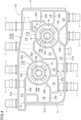
- the upper housing 10a has a substantially rectangular shape in a plan view, and the plurality of tubular ports 1 (inflow and outflow pipes) protrude outward in a horizontal position from the upper housing 10a. As shown in FIGS. 4 , 10, and 11 , the upper housing 10a has a first opening S1 opened downward.
- the upper housing 10a has two valves 2 disposed at a central portion.
- the valve 2 includes a valve body 13 rotatably accommodated inside the tubular portion 12 centered on a vertical axis X.
- the valve body 13 includes an operation shaft 13a protruding in the upper-lower direction.
- the valve 2 includes an electric valve drive unit 14 that drives and rotates the operation shaft 13a of the valve body 13, and the valve drive unit 14 is provided at an upper portion of the upper housing 10a.
- a bearing hole 16a is formed in a bottom plate 16 formed at a lower portion of the tubular portion 12. As described above, an upper end of the operation shaft 13a is connected to the valve drive unit 14, and a lower end of the operation shaft 13a is supported by the bearing hole 16a, whereby the valve body 13 rotates about the vertical axis X to control the flow of the fluid.
- a main annular rib 17 (an example of a first annular rib) is formed at a lower end of the tubular portion 12, and a sub-annular rib 18 (an example of a second annular rib) is formed inside the main annular rib 17.
- the main annular rib 17 (first annular rib) and the sub-annular rib 18 (second annular rib) are disposed coaxially with the vertical axis X.
- the main annular rib 17 has substantially the same radius as the tubular portion 12, and the sub-annular rib 18 has a smaller diameter than the main annular rib 17.
- the main annular rib 17 (first annular rib) includes a first main annular rib 17a formed on the upper housing 10a and a second main annular rib 17b formed on the lower housing 10b.
- the sub-annular rib 18 (second annular rib) includes a first sub-annular rib 18a formed on the upper housing 10a and a second sub-annular rib 18b formed on the lower housing 10b.
- the first main annular rib 17a and the second main annular rib 17b are integrated by welding to form the main annular rib 17.
- the first sub-annular rib 18a and the second sub-annular rib 18b are integrated by welding to form the sub-annular rib 18. The welding will be described later.
- the pump 3 is connected to a flange portion 4 at both ends of the upper housing 10a in a longitudinal direction in a plan view.
- the pump 3 unitizes an electric motor portion 3a and an impeller portion 3b.
- the pump 3 is provided with the impeller portion 3b inserted into an opening of the flange portion 4.
- the upper housing 10a bulges upward at a site where the valve 2 is disposed, and the outer wall 21 (first outer wall rib 21a) at an outer edge portion has the smallest dimension in the upper-lower direction.
- the upper housing 10a includes a vertical wall portion 5 formed integrally on an outer periphery of the upper housing 10a in order to increase a strength of the outer periphery.
- the vertical wall portion 5 has a plate shape rising upward from the outer periphery of the upper housing 10a and is connected in such a manner that an outer surface of the vertical wall portion 5 and an outer surface of the first outer wall rib 21a are flush with each other.
- the vertical wall portion 5 is disposed at a position overlapping the first outer wall rib 21a in a plan view. A part of the tubular ports 1 penetrate the vertical wall portion 5.
- a strength of a part of the outer edge portion of the upper housing 10a is increased by forming the vertical wall portion 5. Since the vertical wall portion 5 is formed, a recessed space opened upward is defined between the vertical wall portion 5 and the upper housing 10a.
- the vertical wall portion 5 forms a drain hole 5a (an example of a liquid discharge hole) for discharging water (liquid) accumulated in the recessed space.
- the lower housing 10b includes a bottom wall 7.
- the lower housing 10b has a second opening S2 opened upward.
- the lower housing 10b is integrated with the upper housing 10a to form the housing 10.
- the first opening S1 shown in FIG. 4 represents a form of an opening of the upper housing 10a before welding.
- the first outer wall rib 21a and a plurality of first partition wall ribs 22a are formed in a region surrounding the outer periphery of the upper housing 10a. Further, the first main annular rib 17a, the first sub-annular rib 18a, and the first partition wall ribs 22a are formed in the first opening S1.
- a first pressure receiving rib region 21ap which is a relatively long region where a pressure of the fluid in the flow path chamber LS acts from the inside, is formed into a curved shape bulging toward a region where the fluid flows (inward: lower side in FIG. 4 ), thereby preventing deformation due to the pressure.
- the flow path chamber LS is formed between the partition walls 22 or between the outer wall 21 and the partition wall 22, and FIG. 4 shows a position of the flow path chamber LS between the plurality of first partition wall ribs 22a or between the first outer wall rib 21a and the first partition wall rib 22a.
- the plurality of tubular ports 1 (inflow and outflow pipes), which are disposed in a penetrating state between the first outer wall rib 21a and the first partition wall rib 22a, are supported in a reinforced state by reinforcement portions T made of resin at sites penetrating the first outer wall rib 21a and the first partition wall rib 22a.
- the second opening S2 shown in FIG. 7 represents a form of an opening of the lower housing 10b before welding.
- the second outer wall rib 21b and a plurality of second partition wall ribs 22b are formed in a region surrounding an outer periphery of the lower housing 10b. Further, the second main annular rib 17b, the second sub-annular rib 18b, and the second partition wall ribs 22b are formed in the second opening S2.
- a position of the flow path chamber LS is shown between the plurality of second partition wall ribs 22b or between the second outer wall rib 21b and the second partition wall rib 22b.
- the second main annular rib 17b and the second sub-annular rib 18b are disposed at positions overlapping the first main annular rib 17a and the first sub-annular rib 18a.
- the plurality of second partition wall ribs 22b are disposed at positions overlapping the corresponding first partition wall ribs 22a.
- the second opening S2 forms the second outer wall rib 21b at a position overlapping the first outer wall rib 21a.
- a second pressure receiving rib region 21bp is formed at a position overlapping the first pressure receiving rib region 21ap.
- the second pressure receiving rib region 21 bp is also formed into a curved shape bulging in a direction (inward) in which the fluid flows, thereby preventing deformation due to a pressure.
- the first outer wall rib 21a, the first partition wall rib 22a, or the like exposed in the first opening S1 may be simply referred to as a "rib”
- the second outer wall rib 21b, the second partition wall rib 22b, or the like exposed in the second opening S2 may also be simply referred to as a "rib”.
- a position where the first outer wall rib 21a and the first partition wall rib 22a formed in the first opening S1 are connected, or a site where the first main annular rib 17a and the first partition wall rib 22a are connected becomes a boundary region having the same shape as a three-way intersection.
- a position where the second outer wall rib 21b and the second partition wall rib 22b formed in the second opening S2 are connected, or a site where the second main annular rib 17b and the second partition wall rib 22b are connected becomes a boundary region having the same shape as a three-way intersection.
- the thermal welding is implemented by joining the first opening S1 and the second opening S2 in such a manner that facing sites are pressed together under heating. In this joining, facing surfaces of the first outer wall rib 21a and the second outer wall rib 21b are joined in a molten state, and the first partition wall rib 22a and the second partition wall rib 22b are joined in a molten state.
- a joining portion dissipates heat uniformly and the resin solidifies.
- a site of the three-way intersection is thicker than the ribs connected thereto, a delay in temperature reduction occurs in a part of the site of the three-way intersection during the thermal welding. Due to such a delay in temperature reduction, a difference in an amount of thermal expansion may cause deformation such as twisting or distortion in joining surfaces.
- a cutout portion N is formed to equalize a thickness at the site of the three-way intersection.
- a thickness Y of each rib is constant, and in order to make the thickness Y constant at the site of the three-way intersection, the cutout portion N has a shape that combines arc surfaces having a radius equal to the thickness Y
- first outer wall rib 21a As an example, when a radius of bending is small at a corner of the first outer wall rib 21a, deformation is likely to occur during the thermal welding. For this reason, a bent shape with a large radius for preventing deformation at the corner portion is also adopted.
- a boundary in the housing 10 where the first opening S1 and the second opening S2 are thermally welded is referred to as a joining portion W.
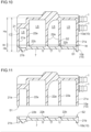
- the joining portion W is disposed below a central position C of the housing 10 in the upper-lower direction. That is, a lower dimension Hb from the joining portion W to a lower end of the lower housing 10b is set to be a value smaller than an upper dimension Ha from the joining portion W to an upper end of the upper housing 10a.
- the upper dimension Ha is approximately four times the lower dimension Hb.
- the upper dimension Ha is preferably twice or more the lower dimension Hb, and more preferably three times or more the lower dimension Hb.
- the outer wall 21 is deformed so as to bulge laterally outward when the pressure of the fluid increases.
- the central position C of the housing 10 (the manifold M) in the upper-lower direction protrudes outward most greatly. Because of this configuration, for example, when the joining portion W is located at the central position C of the housing 10 in the upper-lower direction, a stress caused by the deformation may be concentrated on the joining portion W, and the joining portion W may be damaged.
- the housing 10 is made of a glass fiber reinforced thermoplastic resin.
- this resin has a form in which only the resin is joined at the joining portion W during the thermal welding, and it can be said that the joining surfaces are likely to be damaged when an external force is applied.
- the joining portion W is set below the central position C of the housing 10 in the upper-lower direction.
- the joining portion W in which the first opening S1 of the upper housing 10a and the second opening S2 of the lower housing 10b are joined by thermal welding, is disposed below the central position C of the housing 10 in the upper-lower direction. Therefore, even when the central position C of the outer wall 21 of the housing 10 in the upper-lower direction bulges outward most greatly as the pressure of the fluid flowing inside the housing 10 increases, no stress is concentrated on the joining portion W, and the joining portion W is not damaged.
- the first opening S1 and the second opening S2 are heated by heat from an infrared heat source to melt the ribs exposed in the upper opening S and the ribs exposed in the second opening S2.
- a pressure is applied to the upper housing 10a and the lower housing 10b to join the molten ribs, and the resin solidifies due to heat dissipation, completing the thermal welding.
- the cutout portion N is formed in the boundary region of the three-way intersection of the ribs, thereby allowing uniform heat dissipation at the joining surfaces of the ribs and preventing deformation such as distortion.
- the tubular portion 12 that rotatably accommodates the valve body 13 has a double structure in which the main annular rib 17 and the sub-annular rib 18 disposed at a bottom portion are coaxial, thereby enabling a posture of the tubular portion 12 to be stabilized.
- the main annular rib 17 is formed by thermal welding of the first main annular rib 17a and the second main annular rib 17b
- the sub-annular rib 18 is formed by thermal welding of the first sub-annular rib 18a and the second sub-annular rib 18b. Accordingly, appropriate joining is enabled by satisfactory heat dissipation during the thermal welding without increasing the thickness of the main annular rib 17 and the sub annular rib 18.
- the tubular port 1 penetrating a region from the first outer wall rib 21a to the first partition wall rib 22a is reinforced by the reinforcement portion T at a penetrating site. Accordingly, not only the tubular port 1 is firmly supported but also the outer wall 21 and the partition wall 22 are stabilized in posture, and as a result, shape retention of the housing 10 is improved.
- An outer peripheral portion of the upper housing 10a has increased strength due to the vertical wall portion 5 formed integrally with the outer peripheral portion, thereby a warpage of a welding end surface can be reduced, enabling to ensure a welding area and prevent a welding strength from decreasing.
- water that enters the recessed space can be discharged through the drain hole 5a (liquid discharge hole).
- the joining portion W of the manifold M is set above the central position C of the housing 10 in the upper-lower direction. Also in this configuration, even when the outer wall 21 bulges laterally outward due to action of a pressure of the fluid flowing in the flow path chamber LS, the resin base material containing glass fibers of the upper housing 10a is deformed, thereby preventing a stress acting on the joining portion W from increasing, and preventing inconvenience that causes damage.
- the ribs exposed in the first opening S1 and the second opening S2 are not limited to flat surfaces, and for example, may have shapes including a concave portion and a convex portion that enable portions of a lower end of the first outer wall rib 21a and an upper end of the second outer wall rib 21b to fit together.
- a shape of the cutout portion N is not limited to a combination of the arc surfaces, and for example, may be a concave shape in a plan view by combining short straight lines.
- the first opening S1 of the manifold M has an end surface (lower surface) of a rib lower end portion Rae of an upper rib Ra of the upper housing 10a.
- the second opening S2 of the manifold M has an end surface (upper surface) of a rib upper end portion Rbe of a lower rib Rb of the lower housing 10b.
- the end surface of the rib lower end portion Rae and the end surface of the rib upper end portion Rbe are joined by thermal welding at the joining portion W shown in FIG. 14 .
- a boundary at which the rib lower end portion Rae of the upper rib Ra and the rib upper end portion Rbe of the lower rib Rb are joined is referred to as a welding surface MT in the joining portion W.
- the upper rib Ra is a superordinate concept of each of the first main annular rib 17a, the first sub-annular rib 18a, the first outer wall rib 21a, and the first partition wall rib 22a shown in FIG. 4 .
- the lower rib Rb is a superordinate concept of each of the second main annular rib 17b, the second sub-annular rib 18b, the second outer wall rib 21b, and the second partition wall rib 22b shown in FIG. 7 .
- a thickness of the rib lower end portion Rae of the upper rib Ra (hereinafter referred to as an upper rib width Da) is different from a thickness of the rib upper end portion Rbe of the lower rib Rb (hereinafter referred to as a lower rib width Db).
- the upper rib width Da is set to be smaller than the lower rib width Db (a relationship of Da ⁇ Db). This dimensional relationship may be reversed (Da > Db).
- a reason for setting such a dimensional relationship is to increase a joining strength of the joining portion W by enlarging an area of the joining portion W and to enable welding of the rib lower end portion Rae and the rib upper end portion Rbe within the width in the rib width direction as described above.
- the two ribs having different rib widths are equally heated at the same time in order to perform the thermal welding, it can be confirmed that the temperature of the rib having a smaller rib width becomes higher than that of the rib having a larger rib width because the rib having a smaller rib width has a smaller amount of heat radiation to the outside due to the heat conduction.
- good thermal welding is enabled by reducing the temperature difference between the rib lower end portion Rae of the upper rib Ra and the rib upper end portion Rbe of the lower rib Rb. That is, when heating the rib lower end portion Rae and the rib upper end portion Rbe to perform thermal welding, as shown in FIG. 13 , an infrared heater 26 is disposed between the rib lower end portion Rae of the upper rib Ra and the rib upper end portion Rbe of the lower rib Rb.
- a value of the upper rib width Da is a joining width, and the joining width is set to be 4 mm or more and 8 mm or less.
- the joining width is set to be 4 mm or more and 8 mm or less.
- the upper housing 10a and the lower housing 10b are joined at the joining portion W to form the integrated housing 10. Since the joining portion W is located above or below the center (central position C) of the housing 10 in the upper-lower direction, for example, even when the central position C of an outer wall 21 of the housing 10 in the upper-lower direction bulges outward most greatly as a pressure of the fluid flowing inside the housing 10 increases, no stress is concentrated on the joining portion W, and the joining portion W is not damaged.
- the joining portion W has a cutout portion N that equalizes a thickness of a three-way intersection in a boundary region of the three-way intersection where two partition walls 22, or one partition wall 22 and the outer wall 21 of the housing 10 intersect.
- the thickness is made uniform by forming the cutout portion N, when sites of the three-way intersection are brought into contact under heating, and a temperature is reduced in this contact state, heat is uniformly dissipated at a contact portion, thereby eliminating inconvenience that causes twisting and distortion.
- the valve 2 includes a tubular portion 12 centered on a vertical axis X along the upper-lower direction, and a valve body 13 accommodated in the tubular portion 12 to be rotatable about the vertical axis X, and the joining portion W includes a first annular rib (main annular rib 17) disposed at a lower end position of the tubular portion 12 and a second annular rib (sub-annular rib 18) disposed inside the first annular rib (main annular rib 17) in a region centered on the vertical axis X.
- the first annular rib (main annular rib 17) and the second annular rib (sub-annular rib 18) inside the first annular rib are doubly disposed at the lower end position of the tubular portion 12. Accordingly, a strength of the tubular portion 12 at the lower end position can be increased. It is also possible to increase the strength by providing a thick (wide) annular rib at the lower end position of the tubular portion 12, but this may lead to inconvenience of uneven heat dissipation during thermal welding. On the other hand, by disposing the annular ribs doubly, heat dissipation from the double ribs is uniformly performed.
- the outer wall 21 of the housing 10, which forms the flow path chamber LS relatively long in a direction in which the fluid flows among the plurality of flow path chambers LS, has a curved shape bulging toward the flow path chamber LS.
- the inflow and outflow pipe (tubular port 1) is connected to the outer wall 21 and the partition wall 22, not only the inflow pipe (the tubular port 1) is firmly supported but also a relative positional relationship between the outer wall 21 and the partition wall 22 is stabilized, and as a result, shape retention of the housing 10 is improved.
- a vertical wall portion 5 is formed along an outer periphery of the housing 10, and has a liquid discharge hole (drain hole 5a) for discharging a liquid that enters inside of the vertical wall portion 5.
- a strength of an outer edge portion of the housing 10 can be increased by forming the vertical wall portion 5, thereby a warpage of a welding end surface can be reduced, enabling to ensure a welding area and prevent a welding strength from decreasing.
- a recessed space is formed between the outer periphery of the housing 10 and the vertical wall portion 5, and even when water accumulates in the recessed space, the water can be discharged through the drain hole 5a.
- the first opening S1 is a rib lower end portion Rae of an upper rib Ra extending downward in the upper housing 10a
- the second opening S2 is a rib upper end portion Rbe of a lower rib Rb formed in the lower housing 10b and extending upward
- an upper rib width Da that is a thickness of the rib lower end portion Rae is different from a lower rib width Db that is a thickness of the rib upper end portion Rbe.
- a joining width for thermally welding the rib lower end portion Rae and the rib upper end portion Rbe is 4 mm or more and 8 mm or less.
- thermal welding in a practical width range of 4 mm or more and 8 mm or less can be performed.
- a width of a thinner rib is 75% to 88% of a width of a thicker rib.
- This disclosure can be used for a manifold.
Landscapes
- Engineering & Computer Science (AREA)
- General Engineering & Computer Science (AREA)
- Mechanical Engineering (AREA)
- Chemical & Material Sciences (AREA)
- Combustion & Propulsion (AREA)
- Transportation (AREA)
- Valve Housings (AREA)
Abstract
Description
- This disclosure relates to a manifold.
-
JP 2022-120893A -
Reference 1 discloses the first cooling circuit capable of cooling the fuel cell (FC) by circulating the refrigerant between the fuel cell and the FC radiator using an FC pump. In addition,Reference 1 discloses that cooling of an EVU unit (EVU) is enabled by circulating the refrigerant using an EV pump between the EV radiator and the EVU unit including a motor, an inverter, a battery, and the like. -
JP 2013-23125A - In
Reference 2, the reservoir tank body is made of resin, and an upper end of a melting rib protruding upward from an upper surface of the lower flange is brought into contact with a lower surface of the upper flange, and the lower flange and the upper flange are joined by vibration welding. - As disclosed in
Reference 1, in the cooling system that circulates the refrigerant in flow paths of a plurality of systems, it is desirable to form the pumps and the flow paths integrally in a housing from the viewpoint of handling and mountability on a vehicle body. - In this way, from the viewpoint of handling, mountability, and the like, it is also conceivable to use a manifold that integrates a plurality of flow paths with pumps, valves, and the like in a state in which these are accommodated in a case.
- As a specific configuration, similar to a configuration disclosed in
Reference 2, an upper housing and a lower housing are individually manufactured, and a manifold is formed by welding a flange formed on the upper housing and a flange formed on the lower housing. - In this case, in order to uniformly apply a fluid pressure, it is common to set vertical walls on an outer periphery of the upper housing and vertical walls on an outer periphery of the lower housing to have the same dimension in an upper-lower direction, and to weld these vertical walls at a central position of the manifold in the upper-lower direction.
- On the other hand, when the fluid pressure inside the manifold increases, vertical walls of the manifold are deformed so as to bulge outward. Judging from such deformation, when the vertical walls of the upper housing and the vertical walls of the lower housing are welded at the central position of the manifold in the upper-lower direction, a stress may be concentrated on a welding site, resulting in breakage.
- A need thus exists for a manifold capable of preventing stress concentration on a welding site of upper and lower housings.
- According to an aspect of this disclosure, there is provided a manifold including: a valve configured to control a flow of fluid; and a housing having, in an internal space, a plurality of flow path chambers which is partitioned by a partition wall and through which the fluid flows. The housing includes a joining portion where an upper housing having a first opening opened downward and a lower housing having a second opening opened upward are joined by thermally welding the first opening and the second opening, and the joining portion is disposed above or below a center of the housing in an upper-lower direction.
- According to this configuration, the housing in which the upper housing and the lower housing are integrated is formed by thermally welding the first opening of the upper housing and the second opening of the lower housing. At this time, since a welding site is located above or below the center of the housing in the upper-lower direction, for example, even when a central position of an outer wall of the housing in the upper-lower direction bulges outward most greatly as a pressure of the fluid flowing inside the housing increases, no stress is concentrated on the welding site, and damage at the welding site can be prevented. Therefore, the manifold capable of preventing stress concentration on the welding site of the upper and lower housings is provided.
- The foregoing and additional features and characteristics of this disclosure will become more apparent from the following detailed description considered with the reference to the accompanying drawings, wherein:
-
FIG. 1 is an exploded perspective view of a manifold; -
FIG. 2 is a cross-sectional view of the manifold in a region from a valve to a pump; -
FIG. 3 is a plan view of the manifold; -
FIG. 4 is a bottom view of an upper housing showing a form of a first opening; -
FIG. 5 is a view showing a cutout portion between a first main annular rib and a first partition wall rib; -
FIG. 6 is a view showing a cutout portion between first partition wall ribs; -
FIG. 7 is a plan view of a lower housing showing a form of a second opening; -
FIG. 8 is a view showing a cutout portion between a second main annular rib and a second partition wall rib; -
FIG. 9 is a view showing a cutout portion between second partition wall ribs; -
FIG. 10 is a cross-sectional view of the manifold taken along a line X-X shown inFIG. 3 ; -
FIG. 11 is a cross-sectional view of the manifold separated into the upper housing and the lower housing, taken along the line X-X shown inFIG. 3 ; -
FIG. 12 is a cross-sectional view of the manifold showing a position of a joining portion according to another embodiment (a); -
FIG. 13 is a cross-sectional view showing an arrangement of an upper rib, a lower rib, and the like according to another embodiment (d); -
FIG. 14 is a cross-sectional view of the upper rib and the lower rib in a welded state according to the other embodiment (d); and -
FIG. 15 is a perspective view showing a part of a lower housing according to the other embodiment (d). - Hereinafter, embodiments of a manifold according to this disclosure will be described with reference to the drawings. The manifold controls a flow of fluid that exchanges heat for a battery or the like in an electric vehicle as described below, but is not limited to the following embodiments, and various modifications can be made without departing from the spirit of this disclosure.
- As shown in
FIG. 1 , ahousing 10 includes a plurality of tubular ports 1 (an example of an inflow and outflow pipe), a pair ofvalves 2, and a pair ofpumps 3, and a manifold M is implemented by forming a flow path L (seeFIG. 2 ) in an internal space of thehousing 10. - The manifold M is mounted on an electric vehicle that travels by electric power. The manifold M controls fluid flowing between a cooling target (not shown) such as a battery, an inverter, a traveling motor, and the like mounted on the electric vehicle and a heat dissipation unit (not shown) such as a radiator and a chiller.
- The traveling motor is a traveling drive source that is operated by being supplied with electric power, and the inverter controls the electric power supplied to the traveling motor. The battery is implemented as a rechargeable and dischargeable secondary battery, and supplies electric power to the inverter, the traveling motor, or the like as necessary.
- Examples of the electric vehicle include a hybrid electric vehicle (HEV), a plug-in hybrid electric vehicle (PHEV), a battery electric vehicle (BEV), and a fuel cell electric vehicle (FCEV).
- The manifold M constitutes a part of a temperature management unit (not shown). The temperature management unit includes a control unit (not shown) that acquires signals from sensors such as a battery temperature sensor (not shown) which measures a temperature of the battery, and a fluid temperature sensor (not shown) which measures a temperature of the fluid in the flow path L, and that independently controls the pair of
valves 2 and the pair ofpumps 3. - In the manifold M, a cooling fluid such as a long life coolant (LLC) is used as the fluid. The fluid is not limited to the cooling fluid such as the long life coolant (LLC), and may also be an insulating oil of paraffin-based or the like, or a refrigerant such as hydrofluorocarbon (HFC) or hydrofluoroolefin (HFO).
- The
housing 10 constituting the manifold M is provided in the electric vehicle in a posture shown inFIG. 1 . As shown inFIGS. 1 ,2 , and10 , the manifold M is implemented by thehousing 10 in which anupper housing 10a made of a thermoplastic resin and alower housing 10b made of a thermoplastic resin that is the same material as theupper housing 10a are integrated by thermal welding using an infrared ray. - The
upper housing 10a and thelower housing 10b are molded products using a glass fiber reinforced thermoplastic resin. Fibers used for reinforcement are not limited to glass fibers, and may be high-strength fibers such as carbon fibers. The thermal welding will be described later. - As shown in
FIG. 2 , thehousing 10 has flow path chambers LS, each of which allows the fluid to flow between a plurality ofpartition walls 22 or between anouter wall 21 and thepartition wall 22. The flow path chamber LS communicates with the inside of the presettubular port 1 or atubular portion 12 of thevalve 2. Thevalve 2 controls a flow of the fluid among a plurality of flow path chambers LS. - As shown in
FIGS. 2 ,4 ,7 , and10 , theouter wall 21 includes a firstouter wall rib 21a formed in theupper housing 10a and a secondouter wall rib 21b formed in thelower housing 10b. Thepartition wall 22 includes firstpartition wall ribs 22a formed in theupper housing 10a and secondpartition wall ribs 22b formed in thelower housing 10b. - The first
outer wall rib 21a and the secondouter wall rib 21b are integrated by thermal welding to form theouter wall 21. The firstpartition wall ribs 22a and the secondpartition wall ribs 22b are integrated by thermal welding to form thepartition wall 22. The welding will be described later. - As shown in
FIGS. 3 and4 , theupper housing 10a has a substantially rectangular shape in a plan view, and the plurality of tubular ports 1 (inflow and outflow pipes) protrude outward in a horizontal position from theupper housing 10a. As shown inFIGS. 4 ,10, and 11 , theupper housing 10a has a first opening S1 opened downward. - As shown in
FIGS. 1 and2 , theupper housing 10a has twovalves 2 disposed at a central portion. Thevalve 2 includes avalve body 13 rotatably accommodated inside thetubular portion 12 centered on a vertical axis X. Thevalve body 13 includes anoperation shaft 13a protruding in the upper-lower direction. Thevalve 2 includes an electricvalve drive unit 14 that drives and rotates theoperation shaft 13a of thevalve body 13, and thevalve drive unit 14 is provided at an upper portion of theupper housing 10a. - A
bearing hole 16a is formed in abottom plate 16 formed at a lower portion of thetubular portion 12. As described above, an upper end of theoperation shaft 13a is connected to thevalve drive unit 14, and a lower end of theoperation shaft 13a is supported by thebearing hole 16a, whereby thevalve body 13 rotates about the vertical axis X to control the flow of the fluid. - As shown in
FIGS. 2 and4 , in theupper housing 10a, a main annular rib 17 (an example of a first annular rib) is formed at a lower end of thetubular portion 12, and a sub-annular rib 18 (an example of a second annular rib) is formed inside the mainannular rib 17. - The main annular rib 17 (first annular rib) and the sub-annular rib 18 (second annular rib) are disposed coaxially with the vertical axis X. The main
annular rib 17 has substantially the same radius as thetubular portion 12, and thesub-annular rib 18 has a smaller diameter than the mainannular rib 17. - The main annular rib 17 (first annular rib) includes a first main
annular rib 17a formed on theupper housing 10a and a second mainannular rib 17b formed on thelower housing 10b. The sub-annular rib 18 (second annular rib) includes a firstsub-annular rib 18a formed on theupper housing 10a and a secondsub-annular rib 18b formed on thelower housing 10b. - The first main
annular rib 17a and the second mainannular rib 17b are integrated by welding to form the mainannular rib 17. The firstsub-annular rib 18a and the secondsub-annular rib 18b are integrated by welding to form thesub-annular rib 18. The welding will be described later. - As shown in
FIGS. 1 and2 , thepump 3 is connected to aflange portion 4 at both ends of theupper housing 10a in a longitudinal direction in a plan view. Thepump 3 unitizes anelectric motor portion 3a and animpeller portion 3b. Thepump 3 is provided with theimpeller portion 3b inserted into an opening of theflange portion 4. - The
upper housing 10a bulges upward at a site where thevalve 2 is disposed, and the outer wall 21 (firstouter wall rib 21a) at an outer edge portion has the smallest dimension in the upper-lower direction. As shown inFIGS. 1 and3 , theupper housing 10a includes avertical wall portion 5 formed integrally on an outer periphery of theupper housing 10a in order to increase a strength of the outer periphery. - The
vertical wall portion 5 has a plate shape rising upward from the outer periphery of theupper housing 10a and is connected in such a manner that an outer surface of thevertical wall portion 5 and an outer surface of the firstouter wall rib 21a are flush with each other. Thevertical wall portion 5 is disposed at a position overlapping the firstouter wall rib 21a in a plan view. A part of thetubular ports 1 penetrate thevertical wall portion 5. - A strength of a part of the outer edge portion of the
upper housing 10a is increased by forming thevertical wall portion 5. Since thevertical wall portion 5 is formed, a recessed space opened upward is defined between thevertical wall portion 5 and theupper housing 10a. Thevertical wall portion 5 forms adrain hole 5a (an example of a liquid discharge hole) for discharging water (liquid) accumulated in the recessed space. - As shown in
FIGS. 2 ,7 ,10, and 11 , thelower housing 10b includes abottom wall 7. Thelower housing 10b has a second opening S2 opened upward. When the first opening S1 and the second opening S2 described above are joined by thermal welding, thelower housing 10b is integrated with theupper housing 10a to form thehousing 10. - The first opening S1 shown in
FIG. 4 represents a form of an opening of theupper housing 10a before welding. - In the first opening S1, the first
outer wall rib 21a and a plurality of firstpartition wall ribs 22a are formed in a region surrounding the outer periphery of theupper housing 10a. Further, the first mainannular rib 17a, the firstsub-annular rib 18a, and the firstpartition wall ribs 22a are formed in the first opening S1. - In particular, in the first
outer wall rib 21a, a first pressure receiving rib region 21ap, which is a relatively long region where a pressure of the fluid in the flow path chamber LS acts from the inside, is formed into a curved shape bulging toward a region where the fluid flows (inward: lower side inFIG. 4 ), thereby preventing deformation due to the pressure. - As described above, the flow path chamber LS is formed between the
partition walls 22 or between theouter wall 21 and thepartition wall 22, andFIG. 4 shows a position of the flow path chamber LS between the plurality of firstpartition wall ribs 22a or between the firstouter wall rib 21a and the firstpartition wall rib 22a. - As shown in
FIG. 4 , the plurality of tubular ports 1 (inflow and outflow pipes), which are disposed in a penetrating state between the firstouter wall rib 21a and the firstpartition wall rib 22a, are supported in a reinforced state by reinforcement portions T made of resin at sites penetrating the firstouter wall rib 21a and the firstpartition wall rib 22a. - By forming the reinforcement portion T in this way, not only the
tubular port 1 is firmly supported but also a positional relationship between theouter wall 21 and thepartition wall 22 is appropriately maintained, and as a result, shape retention of thehousing 10 is improved. - The second opening S2 shown in
FIG. 7 represents a form of an opening of thelower housing 10b before welding. - In the second opening S2, the second
outer wall rib 21b and a plurality of secondpartition wall ribs 22b are formed in a region surrounding an outer periphery of thelower housing 10b. Further, the second mainannular rib 17b, the secondsub-annular rib 18b, and the secondpartition wall ribs 22b are formed in the second opening S2. - Similarly to the first opening S1, a position of the flow path chamber LS is shown between the plurality of second
partition wall ribs 22b or between the secondouter wall rib 21b and the secondpartition wall rib 22b. - In the second opening S2, the second main
annular rib 17b and the secondsub-annular rib 18b are disposed at positions overlapping the first mainannular rib 17a and the firstsub-annular rib 18a. The plurality of secondpartition wall ribs 22b are disposed at positions overlapping the corresponding firstpartition wall ribs 22a. - Further, the second opening S2 forms the second
outer wall rib 21b at a position overlapping the firstouter wall rib 21a. A second pressure receiving rib region 21bp is formed at a position overlapping the first pressure receiving rib region 21ap. The second pressure receivingrib region 21 bp is also formed into a curved shape bulging in a direction (inward) in which the fluid flows, thereby preventing deformation due to a pressure. - The first
outer wall rib 21a, the firstpartition wall rib 22a, or the like exposed in the first opening S1 may be simply referred to as a "rib", and the secondouter wall rib 21b, the secondpartition wall rib 22b, or the like exposed in the second opening S2 may also be simply referred to as a "rib". - As shown in
FIGS. 4 and6 , a position where the firstouter wall rib 21a and the firstpartition wall rib 22a formed in the first opening S1 are connected, or a site where the first mainannular rib 17a and the firstpartition wall rib 22a are connected becomes a boundary region having the same shape as a three-way intersection. - As shown in
FIGS. 7 and9 , a position where the secondouter wall rib 21b and the secondpartition wall rib 22b formed in the second opening S2 are connected, or a site where the second mainannular rib 17b and the secondpartition wall rib 22b are connected becomes a boundary region having the same shape as a three-way intersection. - The thermal welding is implemented by joining the first opening S1 and the second opening S2 in such a manner that facing sites are pressed together under heating. In this joining, facing surfaces of the first
outer wall rib 21a and the secondouter wall rib 21b are joined in a molten state, and the firstpartition wall rib 22a and the secondpartition wall rib 22b are joined in a molten state. - After the joining, it is desirable that a joining portion dissipates heat uniformly and the resin solidifies. However, since a site of the three-way intersection is thicker than the ribs connected thereto, a delay in temperature reduction occurs in a part of the site of the three-way intersection during the thermal welding. Due to such a delay in temperature reduction, a difference in an amount of thermal expansion may cause deformation such as twisting or distortion in joining surfaces.
- In order to prevent such inconvenience, as shown in
FIGS. 5, 6 ,8, and 9 , a cutout portion N is formed to equalize a thickness at the site of the three-way intersection. A thickness Y of each rib is constant, and in order to make the thickness Y constant at the site of the three-way intersection, the cutout portion N has a shape that combines arc surfaces having a radius equal to the thickness Y - Taking the first
outer wall rib 21a as an example, when a radius of bending is small at a corner of the firstouter wall rib 21a, deformation is likely to occur during the thermal welding. For this reason, a bent shape with a large radius for preventing deformation at the corner portion is also adopted. - As shown in
FIGS. 2 ,10, and 11 , a boundary in thehousing 10 where the first opening S1 and the second opening S2 are thermally welded is referred to as a joining portion W. - In the manifold M, the joining portion W is disposed below a central position C of the
housing 10 in the upper-lower direction. That is, a lower dimension Hb from the joining portion W to a lower end of thelower housing 10b is set to be a value smaller than an upper dimension Ha from the joining portion W to an upper end of theupper housing 10a. In the present embodiment, the upper dimension Ha is approximately four times the lower dimension Hb. The upper dimension Ha is preferably twice or more the lower dimension Hb, and more preferably three times or more the lower dimension Hb. - In the
housing 10, at a site where a pressure of the fluid flowing in the flow path chamber LS acts on theouter wall 21, theouter wall 21 is deformed so as to bulge laterally outward when the pressure of the fluid increases. - In this deformation, the central position C of the housing 10 (the manifold M) in the upper-lower direction protrudes outward most greatly. Because of this configuration, for example, when the joining portion W is located at the central position C of the
housing 10 in the upper-lower direction, a stress caused by the deformation may be concentrated on the joining portion W, and the joining portion W may be damaged. - In particular, the
housing 10 is made of a glass fiber reinforced thermoplastic resin. However, this resin has a form in which only the resin is joined at the joining portion W during the thermal welding, and it can be said that the joining surfaces are likely to be damaged when an external force is applied. - From a viewpoint of preventing such damage, by setting the lower dimension Hb of the
lower housing 10b smaller than the upper dimension Ha of theupper housing 10a, the joining portion W is set below the central position C of thehousing 10 in the upper-lower direction. - According to such a configuration, even when the
housing 10 is deformed to bulge due to the pressure of the fluid, a resin base material including glass fibers of theupper housing 10a is deformed, thereby reducing the stress acting on the joining portion W and preventing inconvenience that causes damage. - In this way, the joining portion W, in which the first opening S1 of the
upper housing 10a and the second opening S2 of thelower housing 10b are joined by thermal welding, is disposed below the central position C of thehousing 10 in the upper-lower direction. Therefore, even when the central position C of theouter wall 21 of thehousing 10 in the upper-lower direction bulges outward most greatly as the pressure of the fluid flowing inside thehousing 10 increases, no stress is concentrated on the joining portion W, and the joining portion W is not damaged. - In the thermal welding, the first opening S1 and the second opening S2 are heated by heat from an infrared heat source to melt the ribs exposed in the upper opening S and the ribs exposed in the second opening S2. Next, a pressure is applied to the
upper housing 10a and thelower housing 10b to join the molten ribs, and the resin solidifies due to heat dissipation, completing the thermal welding. - In the thermal welding, the cutout portion N is formed in the boundary region of the three-way intersection of the ribs, thereby allowing uniform heat dissipation at the joining surfaces of the ribs and preventing deformation such as distortion.
- The
tubular portion 12 that rotatably accommodates thevalve body 13 has a double structure in which the mainannular rib 17 and thesub-annular rib 18 disposed at a bottom portion are coaxial, thereby enabling a posture of thetubular portion 12 to be stabilized. - The main
annular rib 17 is formed by thermal welding of the first mainannular rib 17a and the second mainannular rib 17b, and thesub-annular rib 18 is formed by thermal welding of the firstsub-annular rib 18a and the secondsub-annular rib 18b. Accordingly, appropriate joining is enabled by satisfactory heat dissipation during the thermal welding without increasing the thickness of the mainannular rib 17 and the subannular rib 18. - By forming the
outer wall 21 on which the pressure from the fluid in the flow path chamber LS acts into a curved shape bulging toward the flow path chamber LS, even when thisouter wall 21 is relatively longer than otherouter walls 21, inconvenience of deforming to bulge outward is eliminated. - The
tubular port 1 penetrating a region from the firstouter wall rib 21a to the firstpartition wall rib 22a is reinforced by the reinforcement portion T at a penetrating site. Accordingly, not only thetubular port 1 is firmly supported but also theouter wall 21 and thepartition wall 22 are stabilized in posture, and as a result, shape retention of thehousing 10 is improved. - An outer peripheral portion of the
upper housing 10a has increased strength due to thevertical wall portion 5 formed integrally with the outer peripheral portion, thereby a warpage of a welding end surface can be reduced, enabling to ensure a welding area and prevent a welding strength from decreasing. By forming thevertical wall portion 5, water that enters the recessed space can be discharged through thedrain hole 5a (liquid discharge hole). - In addition to the above embodiment, this disclosure may be implemented as follows (those having the same functions as the embodiment are denoted by the same reference numerals as in the embodiment).
- (a) As shown in
FIG. 12 , the joining portion W of the manifold M is set above the central position C of thehousing 10 in the upper-lower direction. Also in this configuration, even when theouter wall 21 bulges laterally outward due to action of a pressure of the fluid flowing in the flow path chamber LS, the resin base material containing glass fibers of theupper housing 10a is deformed, thereby preventing a stress acting on the joining portion W from increasing, and preventing inconvenience that causes damage. - (b) The ribs exposed in the first opening S1 and the second opening S2 are not limited to flat surfaces, and for example, may have shapes including a concave portion and a convex portion that enable portions of a lower end of the first
outer wall rib 21a and an upper end of the secondouter wall rib 21b to fit together. - By using the concave portion and the convex portion in this way, it is possible to appropriately maintain a positional relationship between the first opening S1 and the second opening S2 when thermal welding is performed by fitting the concave portion and the convex portion together.
- (c) A shape of the cutout portion N is not limited to a combination of the arc surfaces, and for example, may be a concave shape in a plan view by combining short straight lines.
- (d) As shown in
FIGS. 4 ,13 , and14 , the first opening S1 of the manifold M has an end surface (lower surface) of a rib lower end portion Rae of an upper rib Ra of theupper housing 10a. As shown inFIGS. 7 ,13 , and14 , the second opening S2 of the manifold M has an end surface (upper surface) of a rib upper end portion Rbe of a lower rib Rb of thelower housing 10b. - In the manifold M, the end surface of the rib lower end portion Rae and the end surface of the rib upper end portion Rbe are joined by thermal welding at the joining portion W shown in
FIG. 14 . In the following description, a boundary at which the rib lower end portion Rae of the upper rib Ra and the rib upper end portion Rbe of the lower rib Rb are joined is referred to as a welding surface MT in the joining portion W. - The upper rib Ra is a superordinate concept of each of the first main
annular rib 17a, the firstsub-annular rib 18a, the firstouter wall rib 21a, and the firstpartition wall rib 22a shown inFIG. 4 . The lower rib Rb is a superordinate concept of each of the second mainannular rib 17b, the secondsub-annular rib 18b, the secondouter wall rib 21b, and the secondpartition wall rib 22b shown inFIG. 7 . - In the embodiment (d), as shown in
FIGS. 13 ,14 , and15 , a thickness of the rib lower end portion Rae of the upper rib Ra (hereinafter referred to as an upper rib width Da) is different from a thickness of the rib upper end portion Rbe of the lower rib Rb (hereinafter referred to as a lower rib width Db). In the embodiment (d), the upper rib width Da is set to be smaller than the lower rib width Db (a relationship of Da < Db). This dimensional relationship may be reversed (Da > Db). - By setting the dimensional relationship between the upper rib width Da and the lower rib width Db in this way, even when the rib lower end portion Rae of the upper rib Ra and the rib upper end portion Rbe of the lower rib Rb are displaced from each other in a rib width direction within a tolerance range, for example, it is possible to prevent inconvenience that a widthwise end portion of one of the rib lower end portion Rae of the upper rib Ra and the rib upper end portion Rbe of the lower rib Rb protrudes outward from a widthwise end portion of the other, and to perform thermal welding in a state of being within a width in the rib width direction.
- A reason for setting such a dimensional relationship is to increase a joining strength of the joining portion W by enlarging an area of the joining portion W and to enable welding of the rib lower end portion Rae and the rib upper end portion Rbe within the width in the rib width direction as described above.
- In a structure in which the upper rib width Da and the lower rib width Db are simply increased in order to increase the joining strength of the joining portion W, a weight of the manifold M increases and an amount of resin to be used increases. In order to eliminate this inconvenience, as shown in
FIG. 13 , the upper rib width Da necessary to increase the joining strength of the joining portion W is set, and the lower rib width Db larger than the upper rib width Da is set. - When the two ribs having different rib widths (the rib lower end portion Rae and the rib upper end portion Rbe) are equally heated at the same time in order to perform the thermal welding, it can be confirmed that the temperature of the rib having a smaller rib width becomes higher than that of the rib having a larger rib width because the rib having a smaller rib width has a smaller amount of heat radiation to the outside due to the heat conduction.
- When welding two ribs with a temperature difference between joining surfaces thereof (the end surface of the rib lower end portion Rae and the end surface of the rib upper end portion Rbe), a strength required for the welding surface MT may not be obtained. A reason for this is that, when the two ribs are brought into contact with each other by applying a pressure for welding, it is considered that a fluidity of the molten resin on the joining surface of the rib on a high temperature side is high, and the pressure is not appropriately applied between the two ribs, and the resin in the molten state is not bound with a required force.
- In the embodiment (d), good thermal welding is enabled by reducing the temperature difference between the rib lower end portion Rae of the upper rib Ra and the rib upper end portion Rbe of the lower rib Rb. That is, when heating the rib lower end portion Rae and the rib upper end portion Rbe to perform thermal welding, as shown in
FIG. 13 , aninfrared heater 26 is disposed between the rib lower end portion Rae of the upper rib Ra and the rib upper end portion Rbe of the lower rib Rb. - In the thermal welding, when a temperature exceeds a temperature at which the resin is melted between the end surface of the rib lower end portion Rae and the end surface of the rib upper end portion Rbe by heating by the
infrared heater 26, the heat source is removed, and the rib lower end portion Rae and the rib upper end portion Rbe are brought into contact with each other at an appropriate pressure. - In this way, by bringing the rib lower end portion Rae and the rib upper end portion Rbe into contact with each other at the appropriate pressure, as shown in
FIG. 14 , the resin in the molten state is brought into pressure-contact with each other on the end surfaces, enabling generation of a firmly joined welding surface MT. - In the embodiment (d), a value of the upper rib width Da is a joining width, and the joining width is set to be 4 mm or more and 8 mm or less. In the welding, a part of the molten resin flows out from the boundary of the joining portion W, thereby forming a
burr portion 27. As compared with when the joining width is set to be 3.0 mm, when the joining width is set to be 4.5 mm, a maximum generated stress reduction rate is 48% and a rupture time is 20 times or more. Therefore, the joining width is preferably 4 mm or more and 8 mm or less. - The principles, preferred embodiment and mode of operation of the present invention have been described in the foregoing specification. However, the invention which is intended to be protected is not to be construed as limited to the particular embodiments disclosed. Further, the embodiments described herein are to be regarded as illustrative rather than restrictive. Variations and changes may be made by others, and equivalents employed, without departing from the spirit of the present invention. Accordingly, it is expressly intended that all such variations, changes and equivalents which fall within the spirit and scope of the present invention as defined in the claims, be embraced thereby.
- In the embodiments described above, the following configurations are conceivable.
- (1) A manifold M includes: a
valve 2 configured to control a flow of fluid; and ahousing 10 having, in an internal space, a plurality of flow path chambers LS which is partitioned by apartition wall 22 and through which the fluid flows. Thehousing 10 includes a joining portion W where anupper housing 10a having a first opening S1 opened downward and alower housing 10b having a second opening S2 opened upward are joined by thermally welding the first opening S1 and the second opening S2. The joining portion W is disposed above or below a center (central position C) of thehousing 10 in an upper-lower direction. - According to this characteristic configuration, by thermally welding the first opening S1 of the
upper housing 10a and the second opening S2 of thelower housing 10b, theupper housing 10a and thelower housing 10b are joined at the joining portion W to form theintegrated housing 10. Since the joining portion W is located above or below the center (central position C) of thehousing 10 in the upper-lower direction, for example, even when the central position C of anouter wall 21 of thehousing 10 in the upper-lower direction bulges outward most greatly as a pressure of the fluid flowing inside thehousing 10 increases, no stress is concentrated on the joining portion W, and the joining portion W is not damaged. - (2) In the manifold M according to (1), it is preferable that the joining portion W has a cutout portion N that equalizes a thickness of a three-way intersection in a boundary region of the three-way intersection where two
partition walls 22, or onepartition wall 22 and theouter wall 21 of thehousing 10 intersect. - According to this, since the thickness is made uniform by forming the cutout portion N, when sites of the three-way intersection are brought into contact under heating, and a temperature is reduced in this contact state, heat is uniformly dissipated at a contact portion, thereby eliminating inconvenience that causes twisting and distortion.
- (3) In the manifold M according to (1) or (2), it is preferable that, the
valve 2 includes atubular portion 12 centered on a vertical axis X along the upper-lower direction, and avalve body 13 accommodated in thetubular portion 12 to be rotatable about the vertical axis X, and the joining portion W includes a first annular rib (main annular rib 17) disposed at a lower end position of thetubular portion 12 and a second annular rib (sub-annular rib 18) disposed inside the first annular rib (main annular rib 17) in a region centered on the vertical axis X. - According to this, the first annular rib (main annular rib 17) and the second annular rib (sub-annular rib 18) inside the first annular rib are doubly disposed at the lower end position of the
tubular portion 12. Accordingly, a strength of thetubular portion 12 at the lower end position can be increased. It is also possible to increase the strength by providing a thick (wide) annular rib at the lower end position of thetubular portion 12, but this may lead to inconvenience of uneven heat dissipation during thermal welding. On the other hand, by disposing the annular ribs doubly, heat dissipation from the double ribs is uniformly performed. - (4) In the manifold M according to (1), it is preferable that the
outer wall 21 of thehousing 10, which forms the flow path chamber LS relatively long in a direction in which the fluid flows among the plurality of flow path chambers LS, has a curved shape bulging toward the flow path chamber LS. - According to this, even when a pressure of the fluid flowing in the flow path chamber LS acts, deformation of the
outer wall 21 bulging outward can be prevented. - (5) In the manifold M according to (1), it is preferable that the
outer wall 21 of thehousing 10 and thepartition wall 22 are connected by a part of an inflow and outflow pipe (tubular port 1). - According to this, since the inflow and outflow pipe (tubular port 1) is connected to the
outer wall 21 and thepartition wall 22, not only the inflow pipe (the tubular port 1) is firmly supported but also a relative positional relationship between theouter wall 21 and thepartition wall 22 is stabilized, and as a result, shape retention of thehousing 10 is improved. - (6) In the manifold M according to (1), it is preferable that a
vertical wall portion 5 is formed along an outer periphery of thehousing 10, and has a liquid discharge hole (drainhole 5a) for discharging a liquid that enters inside of thevertical wall portion 5. - According to this, a strength of an outer edge portion of the
housing 10 can be increased by forming thevertical wall portion 5, thereby a warpage of a welding end surface can be reduced, enabling to ensure a welding area and prevent a welding strength from decreasing. A recessed space is formed between the outer periphery of thehousing 10 and thevertical wall portion 5, and even when water accumulates in the recessed space, the water can be discharged through thedrain hole 5a. - (7) In the manifold M according to (1), it is preferable that, the first opening S1 is a rib lower end portion Rae of an upper rib Ra extending downward in the
upper housing 10a, and the second opening S2 is a rib upper end portion Rbe of a lower rib Rb formed in thelower housing 10b and extending upward, and an upper rib width Da that is a thickness of the rib lower end portion Rae is different from a lower rib width Db that is a thickness of the rib upper end portion Rbe. - According to this, even when the rib lower end portion Rae of the upper rib Ra and the rib upper end portion Rbe of the lower rib Rb are in a positional relationship of being displaced from appropriate positions in a rib width direction within a tolerance range, for example, it is possible to prevent inconvenience that a widthwise end portion of one of the rib lower end portion Rae of the upper rib Ra and the rib upper end portion Rbe of the lower rib Rb protrudes outward from a widthwise end portion of the other, and to perform thermal welding in a positional relationship of being within a width in the rib width direction.
- (8) In the manifold M according to (6) and (7), it is preferable that a joining width for thermally welding the rib lower end portion Rae and the rib upper end portion Rbe is 4 mm or more and 8 mm or less.
- According to this, thermal welding in a practical width range of 4 mm or more and 8 mm or less can be performed.
- (9) In the manifold M according to (7), a width of a thinner rib is 75% to 88% of a width of a thicker rib.
- According to this, it is possible to thermally weld the ribs having different rib widths in which the width of the thinner rib is 75% to 88% of the width of the thicker rib.
- This disclosure can be used for a manifold.
Claims (10)
- A manifold (M) comprising:a valve (2) configured to control a flow of fluid; anda housing (10) having, in an internal space, a plurality of flow path chambers (LS) which is partitioned by a partition wall (22) and through which the fluid flows, whereinthe housing includes a joining portion (W) where an upper housing (10a) having a first opening (S1) opened downward and a lower housing (10b) having a second opening (S2) opened upward are joined by thermally welding the first opening and the second opening, andthe joining portion is disposed above or below a center of the housing in an upper-lower direction.
- The manifold according to claim 1, wherein
the joining portion has a cutout portion (N) that equalizes a thickness of a three-way intersection in a boundary region of the three-way intersection where two partition walls, or one partition wall and an outer wall (21) of the housing intersect. - The manifold according to claim 1 or 2, whereinthe valve includes a tubular portion (12) centered on a vertical axis (X) along the upper-lower direction, and a valve body (13) accommodated in the tubular portion to be rotatable about the vertical axis, andthe joining portion includes a first annular rib (17) disposed at a lower end position of the tubular portion and a second annular rib (18) disposed inside the first annular rib in a region centered on the vertical axis.
- The manifold according to claim 1, wherein
an outer wall (21) of the housing which forms the flow path chamber relatively long in a direction in which the fluid flows among the plurality of flow path chambers has a curved shape bulging toward the flow path chamber. - The manifold according to claim 1, wherein
an outer wall (21) of the housing and the partition wall are connected by a part of an inflow and outflow pipe (1). - The manifold according to claim 1, wherein
a vertical wall portion (5) is formed along an outer periphery of the housing. - The manifold according to claim 6, wherein
a vertical wall portion (5) has a liquid discharge hole (5a) for discharging a liquid that enters inside of the vertical wall portion. - The manifold according to claim 1, whereinthe first opening is a rib lower end portion (Rae) of an upper rib (Ra) extending downward in the upper housing, and the second opening is a rib upper end portion (Rbe) of a lower rib (Rb) formed in the lower housing and extending upward, andan upper rib width (Da) that is a thickness of the rib lower end portion is different from a lower rib width (Db) that is a thickness of the rib upper end portion.
- The manifold according to claim 8, wherein
a joining width for thermally welding the rib lower end portion and the rib upper end portion is 4 mm or more and 8 mm or less. - The manifold according to claim 8 or 9, wherein
a width of a thinner rib is 75% to 88% of a width of a thicker rib.
Applications Claiming Priority (2)
| Application Number | Priority Date | Filing Date | Title |
|---|---|---|---|
| JP2023114656 | 2023-07-12 | ||
| JP2024051604A JP2025013145A (en) | 2023-07-12 | 2024-03-27 | Manifold |
Publications (2)
| Publication Number | Publication Date |
|---|---|
| EP4491856A2 true EP4491856A2 (en) | 2025-01-15 |
| EP4491856A3 EP4491856A3 (en) | 2025-03-19 |
Family
ID=91616635
Family Applications (1)
| Application Number | Title | Priority Date | Filing Date |
|---|---|---|---|
| EP24183025.6A Pending EP4491856A3 (en) | 2023-07-12 | 2024-06-19 | Manifold |
Country Status (3)
| Country | Link |
|---|---|
| US (1) | US20250020231A1 (en) |
| EP (1) | EP4491856A3 (en) |
| CN (1) | CN119309034A (en) |
Citations (2)
| Publication number | Priority date | Publication date | Assignee | Title |
|---|---|---|---|---|
| JP2013023125A (en) | 2011-07-25 | 2013-02-04 | Kojima Press Industry Co Ltd | Reservoir tank |
| JP2022120893A (en) | 2021-02-08 | 2022-08-19 | 株式会社Subaru | Fuel cell vehicle with multiple cooling circuits |
Family Cites Families (5)
| Publication number | Priority date | Publication date | Assignee | Title |
|---|---|---|---|---|
| DE3430115C1 (en) * | 1984-08-16 | 1986-01-30 | Bayerische Motoren Werke AG, 8000 München | The volume compensation, the ventilation and storage of serving containers for the liquid cooling system of internal combustion engines |
| FR2816004B1 (en) * | 2000-10-27 | 2003-06-20 | Mark Iv Systemes Moteurs Sa | COOLING ASSEMBLY FOR MOTOR VEHICLES |
| DE102018102542A1 (en) * | 2018-01-29 | 2019-08-01 | Woco Industrietechnik Gmbh | Apparatus for handling fluids and method for producing the same |
| CN115929946A (en) * | 2020-12-31 | 2023-04-07 | 浙江三花汽车零部件有限公司 | A fluid control valve |
| WO2022266945A1 (en) * | 2021-06-24 | 2022-12-29 | 浙江吉利控股集团有限公司 | Multi-channel cooling line integration apparatus, thermal management integration module and electric vehicle |
-
2024
- 2024-06-19 EP EP24183025.6A patent/EP4491856A3/en active Pending
- 2024-07-01 US US18/760,180 patent/US20250020231A1/en active Pending
- 2024-07-11 CN CN202410928989.6A patent/CN119309034A/en active Pending
Patent Citations (2)
| Publication number | Priority date | Publication date | Assignee | Title |
|---|---|---|---|---|
| JP2013023125A (en) | 2011-07-25 | 2013-02-04 | Kojima Press Industry Co Ltd | Reservoir tank |
| JP2022120893A (en) | 2021-02-08 | 2022-08-19 | 株式会社Subaru | Fuel cell vehicle with multiple cooling circuits |
Also Published As
| Publication number | Publication date |
|---|---|
| EP4491856A3 (en) | 2025-03-19 |
| US20250020231A1 (en) | 2025-01-16 |
| CN119309034A (en) | 2025-01-14 |
Similar Documents
| Publication | Publication Date | Title |
|---|---|---|
| JP7134244B2 (en) | refrigerant distributor | |
| KR20250019116A (en) | Battery Module and Battery Pack including the same | |
| WO2022062528A1 (en) | Liquid-cooled battery system and liquid-cooled battery system control method | |
| US11916210B2 (en) | Battery housing for a battery module, battery module with a battery housing and motor vehicle | |
| JP6994303B2 (en) | Heat transfer device for assembled batteries | |
| WO2014162939A1 (en) | Temperature adjustment device | |
| CN110571494B (en) | Cooling structure of vehicle battery | |
| CN113276651A (en) | Vehicle lower structure | |
| EP3319399A1 (en) | Fluid heating device | |
| CN117957694A (en) | Battery rack and energy storage system including the battery rack | |
| CN119812558A (en) | Battery module assembly, battery pack and vehicle | |
| EP4491856A2 (en) | Manifold | |
| CN111211262A (en) | Battery box and box body thereof | |
| US9664412B2 (en) | Heating device | |
| JP2025013145A (en) | Manifold | |
| US20260081255A1 (en) | Traction battery which can be temperature-controlled by means of a fluid | |
| CN220021270U (en) | Power battery pack and vehicle | |
| US12311726B2 (en) | Battery cooling unit intermediate plate with continuous and discontinuous ribs | |
| EP4113717A1 (en) | Battery pack case comprising over-fusion prevention structure | |
| EP4641769A1 (en) | Vehicle heat exchanger | |
| CN114654987A (en) | Vehicle lower structure | |
| CN221961080U (en) | Heat exchange assembly and battery pack | |
| EP4648180A1 (en) | Heat exchanger | |
| US20250300266A1 (en) | Temperature regulator | |
| KR102858962B1 (en) | Battery cooling plate for electric vehicle |
Legal Events
| Date | Code | Title | Description |
|---|---|---|---|
| PUAI | Public reference made under article 153(3) epc to a published international application that has entered the european phase |
Free format text: ORIGINAL CODE: 0009012 |
|
| STAA | Information on the status of an ep patent application or granted ep patent |
Free format text: STATUS: THE APPLICATION HAS BEEN PUBLISHED |
|
| AK | Designated contracting states |
Kind code of ref document: A2 Designated state(s): AL AT BE BG CH CY CZ DE DK EE ES FI FR GB GR HR HU IE IS IT LI LT LU LV MC ME MK MT NL NO PL PT RO RS SE SI SK SM TR |
|
| PUAL | Search report despatched |
Free format text: ORIGINAL CODE: 0009013 |
|
| AK | Designated contracting states |
Kind code of ref document: A3 Designated state(s): AL AT BE BG CH CY CZ DE DK EE ES FI FR GB GR HR HU IE IS IT LI LT LU LV MC ME MK MT NL NO PL PT RO RS SE SI SK SM TR |
|
| RIC1 | Information provided on ipc code assigned before grant |
Ipc: F01P 7/14 20060101ALN20250212BHEP Ipc: H01M 10/60 20140101ALI20250212BHEP Ipc: B60K 11/02 20060101ALI20250212BHEP Ipc: F01P 11/04 20060101ALI20250212BHEP Ipc: F01P 7/16 20060101AFI20250212BHEP |
|
| STAA | Information on the status of an ep patent application or granted ep patent |
Free format text: STATUS: REQUEST FOR EXAMINATION WAS MADE |
|
| 17P | Request for examination filed |
Effective date: 20250904 |
|
| GRAP | Despatch of communication of intention to grant a patent |
Free format text: ORIGINAL CODE: EPIDOSNIGR1 |
|
| STAA | Information on the status of an ep patent application or granted ep patent |
Free format text: STATUS: GRANT OF PATENT IS INTENDED |
|
| RIC1 | Information provided on ipc code assigned before grant |
Ipc: F01P 7/16 20060101AFI20260316BHEP Ipc: F01P 11/04 20060101ALI20260316BHEP Ipc: B60K 11/02 20060101ALI20260316BHEP Ipc: H01M 10/60 20140101ALI20260316BHEP Ipc: F16K 5/02 20060101ALI20260316BHEP Ipc: F16K 11/083 20060101ALI20260316BHEP Ipc: F01P 7/14 20060101ALN20260316BHEP |
|
| INTG | Intention to grant announced |
Effective date: 20260331 |