EP4491833A1 - H-förmiges betonfertigteil zum errichten von lagerstätten - Google Patents
H-förmiges betonfertigteil zum errichten von lagerstätten Download PDFInfo
- Publication number
- EP4491833A1 EP4491833A1 EP24188267.9A EP24188267A EP4491833A1 EP 4491833 A1 EP4491833 A1 EP 4491833A1 EP 24188267 A EP24188267 A EP 24188267A EP 4491833 A1 EP4491833 A1 EP 4491833A1
- Authority
- EP
- European Patent Office
- Prior art keywords
- side walls
- concrete element
- prefab
- floor slab
- reinforcement
- Prior art date
- Legal status (The legal status is an assumption and is not a legal conclusion. Google has not performed a legal analysis and makes no representation as to the accuracy of the status listed.)
- Granted
Links
Images

Classifications
-
- E—FIXED CONSTRUCTIONS
- E04—BUILDING
- E04H—BUILDINGS OR LIKE STRUCTURES FOR PARTICULAR PURPOSES; SWIMMING OR SPLASH BATHS OR POOLS; MASTS; FENCING; TENTS OR CANOPIES, IN GENERAL
- E04H7/00—Construction or assembling of bulk storage containers employing civil engineering techniques in situ or off the site
- E04H7/22—Containers for fluent solids, e.g. silos, bunkers; Supports therefor
- E04H7/24—Constructions, with or without perforated walls, depending on the use of specified materials
- E04H7/26—Constructions, with or without perforated walls, depending on the use of specified materials mainly of concrete, e.g. reinforced concrete or other stone-like materials
-
- E—FIXED CONSTRUCTIONS
- E04—BUILDING
- E04H—BUILDINGS OR LIKE STRUCTURES FOR PARTICULAR PURPOSES; SWIMMING OR SPLASH BATHS OR POOLS; MASTS; FENCING; TENTS OR CANOPIES, IN GENERAL
- E04H7/00—Construction or assembling of bulk storage containers employing civil engineering techniques in situ or off the site
- E04H7/22—Containers for fluent solids, e.g. silos, bunkers; Supports therefor
- E04H2007/225—Silos with retaining wall type wall elements, e.g. trench silos
Definitions
- the invention relates to a prefab concrete element for constructing side walls for storage facilities.
- the invention also relates to a use for constructing a bunker silo.
- BE '691 describes a prefabricated concrete element with a horizontally extending floor slab and two side wall sections extending upwards and towards each other from the floor slab.
- the floor slab always extends laterally over the range in which the side wall sections are connected to the floor slab.
- the side wall sections are connected to each other by a coupling beam.
- the coupling beam is mounted under the top of the side wall sections and forms a horizontal walkway.
- the top of the side wall sections forms a railing on both sides of the horizontal walkway.
- This known prefab element has the following disadvantages. Because the side wall sections converge towards each other, the side wall sections have a wide base at the bottom. This means that the side wall sections are far apart at the bottom near the floor slab. As a result, there is less storage space at the bottom of the storage facility than at the top. This is also disadvantageous for unloading a storage facility because scraping along a side wall of the storage facility with a shovel, such as one from a wheel loader, is not possible.
- the converging side wall sections are additionally disadvantageous at a constant base width because this limits a total height of the prefab element. After all, the walkway must remain accessible. The width of the base cannot simply be increased because this would prevent the prefab element from being loaded onto a truck trailer. The limited height of the prefab element restricts the storage space in the storage facility. Due to the wide base and the converging side walls, the prefab element has a large concrete volume and therefore a significant weight. It is practically necessary to execute the prefab element in two parts.
- the present invention aims to solve at least some of the above problems or drawbacks.
- the current invention relates to a prefab concrete element according to claim 1.
- the two side walls extend perpendicular to the floor slab, a distance between the two side walls at the top of the two side walls is as large as at the level of the floor slab.
- a distance between the two side walls at the top of the two side walls is as large as at the level of the floor slab.
- a wheel loader can scrape up to the side wall of the storage facility, which simplifies loading and unloading in the storage facility.
- the prefab concrete element can be easily manufactured in different heights. This does not affect the walkway, but it is thus possible to construct a storage facility with a greater height and therefore a larger total storage space.
- the prefab concrete element has a limited concrete volume and, consequently, a limited weight, which is advantageous for transport.
- the prefab concrete element due to the ratio of the distance from side wall to side wall to the height of at most 0.50, has a height that is at least twice the distance from side wall to side wall.
- the present invention relates to a use according to claim 15.
- a segment means one or more segments.
- Quoting numerical ranges by endpoints includes all integers, fractions and/or real numbers between the endpoints, these endpoints included.
- concrete cover refers to a minimum distance from the outer side of a concrete structure, such as a prefab concrete element, to the nearest reinforcement steel.
- a monolithic element refers to a concrete element that is cast in one piece or that is cast together in a structurally sound manner, for example, through the use of continuous reinforcement.
- the invention concerns a prefab concrete element for constructing side walls of storage facilities.
- the prefab concrete element comprises a horizontally extending floor slab, two side walls extending upwards from the floor slab, and a coupling beam.
- the side walls extend in a longitudinal direction.
- the floor slab extends laterally over a full length of the side walls in a transverse direction.
- the floor slab extends laterally away from the two side walls.
- the transverse direction and the longitudinal direction are parallel to the floor slab.
- the transverse direction and the longitudinal direction are perpendicular to each other.
- the length of the side walls is measured in the specified longitudinal direction.
- the side walls preferably have an equal height, with the height measured along a height direction, perpendicular to the floor slab, and consequently perpendicular to the longitudinal and transverse directions, and from a bottom side of the floor slab.
- the floor slab is preferably a single slab that also connects the two side walls.
- the coupling beam connects the two side walls to each other below a top of the side walls.
- the top of the side walls is an end of the side walls that is located furthest from the floor slab.
- the coupling beam is preferably a concrete coupling beam.
- the coupling beam is a separately cast concrete element that is attached to the side walls.
- the side walls and the coupling beam are comprised in a single concrete element.
- the coupling beam is designed as a horizontal plane, forming a walkway between the side walls.
- the coupling beam is mounted at such a distance from the top of the two side walls that the side walls form a railing. This is advantageous because a person can safely inspect a storage facility from the walkway formed by the coupling beam. The person does not need to walk on goods in the storage facility and also does not risk falling into the storage facility.
- the prefab concrete element comprises reinforcement.
- the two side walls comprise reinforcement such as a reinforcing mesh or reinforcing bars. This is advantageous for absorbing tensile forces in the concrete of the prefab concrete element.
- the floor slab comprises reinforcement such as a reinforcement mesh or reinforcement bars.
- the coupling beam comprises reinforcement, such as a reinforcement mesh or reinforcement bars. More preferably, the two side walls, the floor slab, and the coupling beam comprise reinforcement, wherein the reinforcement of the side walls, the floor slab, and the coupling beam are interconnected. This is advantageous for transferring tensile forces in the concrete of the prefab concrete element between the two side walls, the floor slab, and the coupling beam.
- the two side walls extend transversely to the floor slab. This means that an angle between the floor slab and each of the two side walls is at least 88° and at most 92°. Preferably, the angle between the floor slab and each of the two side walls is at least 89° and at most 91°. More preferably, the angle between the floor slab and each of the two side walls is 90°.
- the two side walls are parallel. This specifically means that the two side walls, after the placement of the prefab concrete element, form the vertical side walls of a storage facility.
- the two side walls and the coupling beam form an H.
- the lying leg of the H is the coupling beam of the prefab concrete element.
- the prefab concrete element has a ratio of a distance from side wall to side wall to a height of the prefab concrete element that is at most 0.50.
- the distance from side wall to side wall is measured from an exterior side of the prefab concrete element according to the transverse direction.
- the height of the prefab concrete element is measured in the height direction from a bottom side of the floor slab to the top of a side wall.
- the ratio of the distance from side wall to side wall to the height of the prefab concrete element is at most 0.48, more preferably at most 0.46, even more preferably at most 0.44, even more preferably at most 0.42, and most preferably at most 0.40.
- the two side walls extend perpendicular to the floor slab, a distance between the two side walls at the top of the two side walls is as large as at the level of the floor slab.
- a distance between the two side walls at the top of the two side walls is as large as at the level of the floor slab.
- a wheel loader can scrape up to the side wall of the storage facility, which simplifies loading and unloading in the storage facility.
- the prefab concrete element can be easily manufactured in different heights. This does not affect a width of the walkway because the two side walls are parallel, and for the same reason does not affect the distance between the side walls at the level of the floor slab.
- the prefab concrete element has a limited concrete volume and, consequently, a limited weight, which is advantageous for transport.
- the prefab concrete element due to the ratio of the distance from side wall to side wall to the height of the prefab concrete element of at most 0.50, has a height that is at least twice the distance from side wall to side wall.
- the prefab concrete element is a monolithic element.
- the prefab concrete element is cast in one go, for example, by pouring concrete into a mold.
- the prefab concrete element comprises reinforcement, as in a previously described embodiment, the reinforcement is placed in the mold before casting.
- a monolithic element is advantageous because the prefab concrete element can be cast in a single step and later, when constructing a side wall of a storage facility, the prefab concrete element can be placed in a single step. This embodiment is possible because a prefab concrete element, according to the first aspect, has a limited concrete volume and consequently a limited weight, allowing the prefab concrete element to be placed and transported as a monolithic element on a truck trailer.
- the prefab concrete element has a length-to-height ratio that is at most 0.85.
- the length of the prefab concrete element is measured in the longitudinal direction from a first end of a side wall to an opposite second end of the side wall.
- the height of the prefab concrete element is measured in the height direction from a bottom side of the floor slab to the top of a side wall.
- the prefab concrete element preferably has a greatest possible height for a largest possible storage space on the same surface area. From a greater height, the prefab concrete element will have too much weight for transport on a truck, making it necessary to limit the length of the prefab concrete element to reduce the weight.
- the prefab concrete element preferably has a greatest possible length so that as few prefab elements as possible are needed to construct a side wall of a storage facility. Once again, it will be necessary to limit the height of the prefab concrete element from a certain length onwards in order to reduce the weight of the prefab concrete element. A length-height ratio of at most 0.85 is advantageous for a prefab concrete element with maximum dimensions in length and height and with an acceptable weight.
- the prefab concrete element has a length-to-height ratio of at least 0.31, preferably at least 0.33, more preferably at least 0.32, even more preferably at least 0.35, and most preferably at least 0.37.
- a length-to-height ratio of at least 0.31 ensures that the prefab concrete element always has sufficient length to quickly construct side walls of a storage facility.
- the prefab concrete element has a width-to-height ratio of at least 0.65, preferably at least 0.70, more preferably at least 0.75, and even more preferably at least 0.80. This is advantageous because the floor slab is now sufficiently wide to prevent the prefab concrete element from tilting laterally when goods are stacked against the prefab concrete element in the storage facility.
- the walkway formed by the coupling beam is at least 1.0 m below the top of the two side walls.
- the coupling beam is located at least 1.1 m below the top of the side walls, more preferably at least 1.2 m. This is advantageous because the railing formed by the two side walls thereby automatically has a safety-required height of 1.0 m.
- the walkway formed by the coupling beam is at most 1.3 meters below the top of the two side walls. This is advantageous as otherwise the railing becomes too high and hinders easy inspection of the storage facility. This is additionally advantageous because this results in the section of the side wall above the coupling beam having a maximum length of 1.3 m, as a result of which goods in the storage facility only exert a limited torque on the mentioned section of the side walls. As a result, a thickness of 12 cm of concrete for the mentioned section of the side walls is sufficient to prevent this section from cracking off the prefab concrete element due to torque effects.
- the prefab concrete element has a concrete cover of at least 25 mm.
- the prefab concrete element has a concrete cover of at least 26 mm, more preferably at least 27 mm, even more preferably at least 28 mm, even more preferably at least 29 mm, and most preferably at least 30 mm.
- the prefab concrete element comprises a reinforcement
- This is, for example, the case with a bunker silo on a farm in which, for example, manure or corn can be stored, from which liquids can seep that act on the concrete.
- Due to a concrete cover of at least 25 mm, the prefab concrete element has a layer of concrete that can serve as a sacrificial layer to protect the reinforcement against oxidation. This increases the lifespan of the prefab concrete element.
- the floor slab, the two side walls, and the coupling beam delimit a beam-shaped volume.
- the beam-shaped volume is open at ends according to the longitudinal direction. This simplifies the manufacturing of the prefab concrete element by pouring concrete into a mold and reduces the total weight of the prefab concrete element.
- the prefab concrete element within the beam-shaped volume comprises a concrete reinforcement volume in corners formed by the floor slab and the two side walls.
- the prefab concrete element within the beam-shaped volume comprises a concrete reinforcement volume in corners formed by the coupling beam and the two side walls.
- the concrete reinforcement volumes extend along the entire length of the side walls.
- the concrete reinforcement volumes in the corners formed by the floor slab and the two side walls are bounded by the floor slab, a side wall, and an inclined wall.
- the concrete reinforcement volumes in the corners formed by the coupling beam and the two side walls are bounded by the coupling beam, a side wall, and an inclined wall.
- the concrete reinforcement volume is a triangular prism. Concrete is very good at withstanding compressive forces, but not at withstanding tensile forces.
- the concrete reinforcement volumes are advantageous for locally increasing a concrete thickness of the prefab concrete element, thereby obtaining a larger lever arm in the mentioned corners. This is additionally advantageous for locally optimizing a quantity of reinforcement.
- the beam-shaped volume with the concrete reinforcement volumes in the corners formed by the floor slab and the two side walls, and optionally in the corners formed by the coupling beam and the two side walls, ensures a very sturdy structure, making it possible to have a prefab concrete element with side walls standing perpendicular to the floor slab and with a height of more than 4 meters, which is suitable for withstanding high loads by storing goods against a side wall of a storage facility.
- the prefab concrete element comprises, in corners formed by the floor slab and a side wall and outside a volume bounded by the floor slab, the two side walls and the coupling beam, a concrete reinforcement volume.
- the volume delimited by the floor slab, the two side walls, and the coupling beam corresponds to the previously described beam-shaped volume, wherein the beam-shaped volume may or may not comprise concrete reinforcement volumes, as in the previously described embodiment.
- the concrete reinforcement volumes outside the beam-shaped volume extend over the entire length of the side walls.
- the concrete reinforcement volumes are bounded by the floor slab, a side wall, and an inclined wall.
- the concrete reinforcement volume is a triangular prism.
- the concrete reinforcement volumes are advantageous for locally increasing a concrete thickness of the prefab concrete element, thereby obtaining a larger lever arm in the mentioned corners. This is additionally advantageous for locally optimizing a quantity of reinforcement.
- This embodiment is particularly advantageous in combination with a previously described embodiment in which the prefab concrete element comprises a concrete reinforcement element in corners of the beam-shaped volume. This creates a very robust structure.
- the two side walls, the floor slab, and the coupling beam comprise a reinforcement mesh.
- the prefab concrete element comprises concrete reinforcement volumes, as in previously described embodiments. Concrete reinforcement volumes within the beam-shaped volume in corners formed by the floor slab and the two side walls comprise a reinforcement mesh. Preferably, each concrete reinforcement volume comprises a reinforcement mesh.
- the reinforcement mesh of a concrete reinforcement volume is substantially parallel to the inclined wall. The reinforcement mesh of a concrete reinforcement volume in corners formed by the floor slab and the two side walls penetrates through the reinforcement mesh in both the floor slab and a side wall. The reinforcement mesh of an optional concrete reinforcement volume in corners formed by the coupling beam and the two side walls penetrates through the reinforcement mesh in both the coupling beam and a side wall.
- ends of the reinforcement mesh in the concrete reinforcement volume are bent in a direction away from the corner in which the concrete reinforcement volume is placed.
- An end of the reinforcement mesh in the concrete reinforcement volume is located within the floor slab, one of the two side walls, or the coupling beam. It is clear that with concrete reinforcement volumes in corners formed by a side wall and the floor slab, an end of the reinforcement mesh lies either within the said side wall or within the floor slab. It will also be apparent that a first end lies within the said side wall and a second end within the floor slab. It is clear that with concrete reinforcement volumes in corners formed by a side wall and the coupling beam, an end of the reinforcement mesh lies either within the said side wall or within the coupling beam.
- the reinforcing mesh in the concrete reinforcement volume extends over at least 80% of the length of the concrete reinforcement volume, preferably at least 85% and more preferably at least 90%.
- the length of the concrete reinforcement volume is measured along the longitudinal direction.
- the reinforcing mesh is a grid of bars. The bars have a diameter of at least 6 mm, preferably at least 8 mm, more preferably at least 9 mm and even more preferably at least 10 mm.
- This embodiment is particularly advantageous for reinforcing the aforementioned corners in the event that a moment causes the aforementioned corners to stretch.
- the reinforcement mesh will absorb the forces responsible for the elongation, thereby preventing the concrete in the aforementioned corners from cracking during elongation.
- Bending of the ends of the reinforcement mesh in the concrete reinforcement volume is advantageous for a good connection of the reinforcement mesh in the concrete reinforcement volume with reinforcement meshes in the rest of the prefab concrete element, thereby better distributing forces.
- each concrete reinforcement volume has a height of at least 30 cm and a width of at least 2 cm.
- the concrete reinforcement volume is as in previously described embodiments.
- the height of the concrete reinforcement volumes is measured according to the height direction.
- the width of the concrete reinforcement volumes is measured according to the transverse direction.
- a concrete reinforcement volume with such dimensions is sufficiently large to reinforce the prefab concrete element in the corners.
- the width of the concrete reinforcement volume is preferably at most 6 cm, more preferably at most 5 cm. This is advantageous in causing as little inconvenience as possible, for example, to a wheel loader.
- the prefab concrete element has a maximum length of 2.5 m. This is particularly advantageous because the prefab concrete element can be placed transversely on a trailer if the prefab concrete element has a floor slab with a width greater than 2.5 m.
- lifting anchors are provided at at least one end of the prefab concrete element along the longitudinal direction.
- Each lifting anchor is positioned between at least two reinforcement bars.
- the at least two extend parallel in the floor slab, the coupling beam, or a side wall.
- the at least two reinforcement bars are woven around the lifting anchor at the level of the lifting anchor.
- the prefab concrete element comprises two lifting anchors in the floor slab and two lifting anchors in the coupling beam.
- This embodiment is advantageous for lifting the prefab concrete element, particularly when the prefab concrete element is laid on a side.
- Weaving the at least two reinforcement bars is advantageous to prevent the lifting anchors from being pulled out of the prefab concrete element. This is particularly advantageous if the prefab concrete element is hoisted only at lifting anchors near a top of the prefab concrete element to tilt the prefab concrete element from a lying to a standing position.
- lifting anchors are placed in the walkway formed by the coupling beam. More preferably, these lifting anchors in the walkway are also placed between at least two reinforcement bars, as previously described for the lifting anchors at the ends of the prefab concrete element. These lifting anchors are advantageous for lifting the prefab concrete element in a standing position.
- a ratio of a distance from side wall to side wall to the width of the prefab concrete element is at most 0.50, preferably at most 0.45, and more preferably at most 0.43.
- the distance from side wall to side wall is measured from an exterior side of the prefab concrete element according to the transverse direction.
- the two side walls have a minimum thickness of 12 cm, the floor slab a minimum thickness of 16 cm, and the coupling beam a minimum thickness of 18 cm.
- the floor slab has a minimum thickness of 17 cm, more preferably a minimum thickness of 18 cm.
- the coupling beam has a minimum thickness of 19 cm, more preferably a minimum thickness of 20 cm.
- the two side walls preferably have a maximum thickness of 23 cm.
- the floor slab preferably has a maximum thickness of 20 cm.
- the coupling beam preferably has a maximum thickness of 21 cm.
- This embodiment is advantageous for obtaining a strong prefab concrete element with a minimal weight.
- the prefab concrete element comprises a groove at a first end of the side walls in the longitudinal direction.
- the groove extends in the height direction over an entire height of the prefab concrete element.
- the prefab concrete element comprises at an opposite second end of the side walls along the longitudinal direction an identical groove or a complementary protrusion.
- the groove at the said first end is configured to receive the protrusion.
- the groove is advantageous for sealing a joint between two adjacent prefab concrete elements by placing a sealing element in the groove, such as a sealing rubber, or by incorporating the complementary protrusion into the groove. For example, this prevents liquids from seeping out of a storage facility.
- the invention relates to a use of a prefab concrete element according to the first aspect for constructing a bunker silo.
- Figure 1 shows a side view of an H-shaped concrete element according to an embodiment of the present invention.
- the prefab concrete element (1) is a monolithic element.
- the prefab concrete element (1) comprises a horizontally extending floor slab (2), two side walls (3) extending upwards perpendicular to the floor slab (2), and a coupling beam (4).
- the side walls (3) extend in a longitudinal direction (19).
- the longitudinal direction (19) is not shown in Figure 1 , but it is perpendicular to the plane formed by the side view.
- the longitudinal direction (19) is indicated in Figure 2 .
- the two side walls (3) and the coupling beam (4) form an H.
- the floor slab (2) extends over a full length of the side walls (3) in a transverse direction (7).
- the floor slab (2) extends in a direction away from the side walls (3).
- the coupling beam (4) connects the two side walls (3) to each other below a top of the side walls (3).
- the coupling beam (3) is designed as a horizontal plane, forming a walkway (5) between the side walls (3).
- the walkway (5) is located at a distance (18) of 1 m from the top of the side walls (3).
- the side walls (3) thus form a railing (6).
- the prefab concrete element (1) has a width (16) measured in the transverse direction (7) from a first end of the floor slab (2) to an opposite end of 295 cm.
- the prefab concrete element (1) has a height (17) measured in a height direction (8) from a bottom side of the floor slab (2) to the top of the side walls (3) of 423 cm.
- the height direction (8) is perpendicular to the bottom side of the floor slab (2).
- the prefab concrete element (1) has a width-height ratio that is 0.70 in this embodiment.
- the floor slab (2), the two side walls (3), and the coupling beam (4) delimit a beam-shaped volume (9).
- the beam-shaped volume (9) is open at ends along the longitudinal direction (19).
- concrete reinforcement volumes (10) are located in corners formed by the floor slab (2) and the two side walls (3), and in corners formed by the coupling beam (4) and the two side walls (3).
- outside the beam-shaped volume (9) there are also concrete reinforcement volumes (11) in corners formed by the floor slab (2) and the two side walls (3).
- the concrete reinforcement volumes (10, 11) extend over the entire length of the side walls (3).
- the concrete reinforcement volumes (10) at the bottom of the beam-shaped volume (9) are bounded by the floor slab (2), a side wall (3), and an inclined wall.
- the concrete reinforcement volumes (10) at the top of the beam-shaped volume (9) are bounded by the coupling beam (4), a side wall (3), and an inclined wall.
- the concrete reinforcement volumes (10) have a width of 5 cm and a height of 40 cm.
- the concrete reinforcement volumes (11) outside the beam-shaped volume (9) are bounded by the floor slab (2), a side wall (3), and an inclined wall.
- the concrete reinforcement volumes (11) have a width of 2.5 cm and a height of 40 cm.
- a groove (12) which extends in the height direction (8) over the full height (17) of the prefab concrete element (1).
- an identical groove (12) or a complementary protrusion is present at an opposite second end of the side walls (3).
- the groove (12) is advantageous for sealing a joint between two adjacent prefab concrete elements (1) by placing a sealing element in the groove (12), such as a sealing rubber, or by incorporating the complementary protrusion into the groove (12).
- lifting anchors (13) are provided at ends of the prefab concrete element (1) along the longitudinal direction (19). Each lifting anchor (13) is placed between two reinforcement bars (14).
- the two reinforcement bars (14) around the lifting anchors (13) in the floor slab (2) extend parallel in the floor slab (2).
- the two reinforcement bars (14) around the lifting anchors (13) in the coupling beam (4) extend parallel in the coupling beam (4) and are folded over at an end, after which the two reinforcement bars (14) extend parallel and in opposite directions in the side walls (3).
- the two reinforcement bars (14) are woven around the lifting anchor (13) at the level of a lifting anchor (13).
- the prefab concrete element (1) has a distance (15) from side wall (3) to side wall (3) of 124 cm. The distance (15) is measured from an exterior side of the prefab concrete element (1).
- the prefab concrete element has a ratio of the distance (15) from side wall (3) to side wall (3) to the height (17) of the prefab concrete element (1) of 0.29.
- the prefab concrete element has a ratio of the distance (15) from side wall (3) to side wall (3) to the width (16) of the prefab concrete element (1) of 0.42.
- the side walls (3) have a minimum thickness of 12 cm
- the floor slab has a minimum thickness of 18 cm
- the coupling beam has a minimum thickness of 20 cm.
- the prefab concrete element (1) has a concrete cover of at least 30 mm.
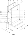
- Figure 2 shows a perspective view of an H-shaped concrete element according to an embodiment of the present invention.
- the prefab concrete element (1) corresponds to the embodiment depicted in Figure 1 .
- the prefab concrete element (1) has a length (20) measured along the longitudinal direction (19) from a first end of a side wall (3) to a second opposite end of the side wall (3) of 250 cm.
- the prefab concrete element (1) has a length-to-width ratio of 0.85.
Landscapes
- Engineering & Computer Science (AREA)
- Architecture (AREA)
- General Engineering & Computer Science (AREA)
- Civil Engineering (AREA)
- Structural Engineering (AREA)
- On-Site Construction Work That Accompanies The Preparation And Application Of Concrete (AREA)
- Road Paving Structures (AREA)
Priority Applications (1)
| Application Number | Priority Date | Filing Date | Title |
|---|---|---|---|
| EP26152150.4A EP4707499A1 (de) | 2023-07-12 | 2024-07-12 | H-förmiges betonfertigteil zum errichten von lagerstätten |
Applications Claiming Priority (1)
| Application Number | Priority Date | Filing Date | Title |
|---|---|---|---|
| BE20235585A BE1031797B1 (nl) | 2023-07-12 | 2023-07-12 | H-vormig betonnen prefab element voor het construeren van opslagplaatsen |
Related Child Applications (1)
| Application Number | Title | Priority Date | Filing Date |
|---|---|---|---|
| EP26152150.4A Division EP4707499A1 (de) | 2023-07-12 | 2024-07-12 | H-förmiges betonfertigteil zum errichten von lagerstätten |
Publications (3)
| Publication Number | Publication Date |
|---|---|
| EP4491833A1 true EP4491833A1 (de) | 2025-01-15 |
| EP4491833C0 EP4491833C0 (de) | 2026-02-11 |
| EP4491833B1 EP4491833B1 (de) | 2026-02-11 |
Family
ID=87245769
Family Applications (2)
| Application Number | Title | Priority Date | Filing Date |
|---|---|---|---|
| EP26152150.4A Pending EP4707499A1 (de) | 2023-07-12 | 2024-07-12 | H-förmiges betonfertigteil zum errichten von lagerstätten |
| EP24188267.9A Active EP4491833B1 (de) | 2023-07-12 | 2024-07-12 | H-förmiges betonfertigteil für den bau von lagerhallen |
Family Applications Before (1)
| Application Number | Title | Priority Date | Filing Date |
|---|---|---|---|
| EP26152150.4A Pending EP4707499A1 (de) | 2023-07-12 | 2024-07-12 | H-förmiges betonfertigteil zum errichten von lagerstätten |
Country Status (2)
| Country | Link |
|---|---|
| EP (2) | EP4707499A1 (de) |
| BE (1) | BE1031797B1 (de) |
Citations (2)
| Publication number | Priority date | Publication date | Assignee | Title |
|---|---|---|---|---|
| DE102012005098A1 (de) * | 2012-03-14 | 2013-09-19 | N.V. Vanbockrijck | Betonfertigbauteil zur Erstellung von Seitenwänden für Fahrsilos und Seitenwand für ein Fahrsilo |
| DE202015102016U1 (de) * | 2015-04-23 | 2015-07-01 | Zink GmbH Betonwerk und Abwassersysteme | Fahrsilo |
-
2023
- 2023-07-12 BE BE20235585A patent/BE1031797B1/nl active IP Right Grant
-
2024
- 2024-07-12 EP EP26152150.4A patent/EP4707499A1/de active Pending
- 2024-07-12 EP EP24188267.9A patent/EP4491833B1/de active Active
Patent Citations (2)
| Publication number | Priority date | Publication date | Assignee | Title |
|---|---|---|---|---|
| DE102012005098A1 (de) * | 2012-03-14 | 2013-09-19 | N.V. Vanbockrijck | Betonfertigbauteil zur Erstellung von Seitenwänden für Fahrsilos und Seitenwand für ein Fahrsilo |
| DE202015102016U1 (de) * | 2015-04-23 | 2015-07-01 | Zink GmbH Betonwerk und Abwassersysteme | Fahrsilo |
Also Published As
| Publication number | Publication date |
|---|---|
| EP4491833C0 (de) | 2026-02-11 |
| BE1031797B1 (nl) | 2025-02-12 |
| EP4707499A1 (de) | 2026-03-11 |
| EP4491833B1 (de) | 2026-02-11 |
| BE1031797A1 (nl) | 2025-02-05 |
Similar Documents
| Publication | Publication Date | Title |
|---|---|---|
| AU697706B2 (en) | Flotation system for buildings | |
| US8360688B2 (en) | Ballast-filled pipeline weight | |
| HU223401B1 (hu) | Építő rakodóállvány és hibrid építő rakodóállvány | |
| US7607274B1 (en) | Method of constructing a building in a typically flood prone area employing a pre-cast concrete chain wall | |
| US20150361686A1 (en) | Base for Supporting an Upstanding Mast | |
| US8141323B2 (en) | Apparatus and system to increase capacity of granular material storage structures | |
| US20050019127A1 (en) | Contrail shipping platform | |
| EP4491833B1 (de) | H-förmiges betonfertigteil für den bau von lagerhallen | |
| US6786689B2 (en) | Low profile deadman and method for shipping the same with a tank | |
| EP0334265A1 (de) | Tank-Container | |
| US8789722B2 (en) | Bedding box for use with compact excavator | |
| EP0468827B1 (de) | Bewegliche, schwere, selbständige und selbstaufrichtende Zentrale für die Herstellung von Beton | |
| US4966293A (en) | Transport and/or storage container for liquids and finely divided bulk solids | |
| US3426541A (en) | Earth supporting structures | |
| US4038795A (en) | Concrete storage tank and method of making same | |
| RU2516835C2 (ru) | Кузов-платформа | |
| PL238424B1 (pl) | Kontener samowyładowczy zwłaszcza do materiałów sypkich | |
| JP7443207B2 (ja) | コンクリート打設方法、およびコンクリート打設システム | |
| WO1996018777A1 (en) | A method to build vertical wall portions of reinforced concrete, as well as construction shore, mounting element and construction element intended to be used in the method | |
| EP2578371A1 (de) | Demontierbare Anlage zur Betonfertigung | |
| AU2016102095A4 (en) | Modular gantry structure | |
| RU216304U1 (ru) | Блок подпорной стены | |
| GB2139276A (en) | Grain barrier | |
| RU238765U1 (ru) | Устройство для хранения и транспортировки противовесных грузов трубоукладчика | |
| US12552599B2 (en) | Modular particulate storage system |
Legal Events
| Date | Code | Title | Description |
|---|---|---|---|
| PUAI | Public reference made under article 153(3) epc to a published international application that has entered the european phase |
Free format text: ORIGINAL CODE: 0009012 |
|
| STAA | Information on the status of an ep patent application or granted ep patent |
Free format text: STATUS: THE APPLICATION HAS BEEN PUBLISHED |
|
| AK | Designated contracting states |
Kind code of ref document: A1 Designated state(s): AL AT BE BG CH CY CZ DE DK EE ES FI FR GB GR HR HU IE IS IT LI LT LU LV MC ME MK MT NL NO PL PT RO RS SE SI SK SM TR |
|
| STAA | Information on the status of an ep patent application or granted ep patent |
Free format text: STATUS: REQUEST FOR EXAMINATION WAS MADE |
|
| 17P | Request for examination filed |
Effective date: 20250303 |
|
| GRAP | Despatch of communication of intention to grant a patent |
Free format text: ORIGINAL CODE: EPIDOSNIGR1 |
|
| STAA | Information on the status of an ep patent application or granted ep patent |
Free format text: STATUS: GRANT OF PATENT IS INTENDED |
|
| INTG | Intention to grant announced |
Effective date: 20251110 |
|
| GRAS | Grant fee paid |
Free format text: ORIGINAL CODE: EPIDOSNIGR3 |
|
| GRAA | (expected) grant |
Free format text: ORIGINAL CODE: 0009210 |
|
| STAA | Information on the status of an ep patent application or granted ep patent |
Free format text: STATUS: THE PATENT HAS BEEN GRANTED |
|
| AK | Designated contracting states |
Kind code of ref document: B1 Designated state(s): AL AT BE BG CH CY CZ DE DK EE ES FI FR GB GR HR HU IE IS IT LI LT LU LV MC ME MK MT NL NO PL PT RO RS SE SI SK SM TR |
|
| REG | Reference to a national code |
Ref country code: CH Ref legal event code: F10 Free format text: ST27 STATUS EVENT CODE: U-0-0-F10-F00 (AS PROVIDED BY THE NATIONAL OFFICE) Effective date: 20260211 Ref country code: GB Ref legal event code: FG4D |
|
| REG | Reference to a national code |
Ref country code: CH Ref legal event code: R17 Free format text: ST27 STATUS EVENT CODE: U-0-0-R10-R17 (AS PROVIDED BY THE NATIONAL OFFICE) Effective date: 20260223 |
|
| REG | Reference to a national code |
Ref country code: DE Ref legal event code: R096 Ref document number: 602024002494 Country of ref document: DE |
|
| REG | Reference to a national code |
Ref country code: IE Ref legal event code: FG4D |
|
| U01 | Request for unitary effect filed |
Effective date: 20260304 |
|
| U07 | Unitary effect registered |
Designated state(s): AT BE BG DE DK EE FI FR IT LT LU LV MT NL PT RO SE SI Effective date: 20260310 |