EP4491813A2 - Abdecksystem für einen toilettentank - Google Patents
Abdecksystem für einen toilettentank Download PDFInfo
- Publication number
- EP4491813A2 EP4491813A2 EP24188125.9A EP24188125A EP4491813A2 EP 4491813 A2 EP4491813 A2 EP 4491813A2 EP 24188125 A EP24188125 A EP 24188125A EP 4491813 A2 EP4491813 A2 EP 4491813A2
- Authority
- EP
- European Patent Office
- Prior art keywords
- toilet
- receptacle
- tank
- water
- lid
- Prior art date
- Legal status (The legal status is an assumption and is not a legal conclusion. Google has not performed a legal analysis and makes no representation as to the accuracy of the status listed.)
- Pending
Links
Images


Classifications
-
- E—FIXED CONSTRUCTIONS
- E03—WATER SUPPLY; SEWERAGE
- E03D—WATER-CLOSETS OR URINALS WITH FLUSHING DEVICES; FLUSHING VALVES THEREFOR
- E03D9/00—Sanitary or other accessories for lavatories ; Devices for cleaning or disinfecting the toilet room or the toilet bowl; Devices for eliminating smells
- E03D9/02—Devices adding a disinfecting, deodorising, or cleaning agent to the water while flushing
- E03D9/03—Devices adding a disinfecting, deodorising, or cleaning agent to the water while flushing consisting of a separate container with an outlet through which the agent is introduced into the flushing water, e.g. by suction ; Devices for agents in direct contact with flushing water
- E03D9/031—Devices connected to or dispensing into the flushing pipe
-
- E—FIXED CONSTRUCTIONS
- E03—WATER SUPPLY; SEWERAGE
- E03D—WATER-CLOSETS OR URINALS WITH FLUSHING DEVICES; FLUSHING VALVES THEREFOR
- E03D1/00—Water flushing devices with cisterns ; Setting up a range of flushing devices or water-closets; Combinations of several flushing devices
- E03D1/01—Shape or selection of material for flushing cisterns
- E03D1/012—Details of shape of cisterns, e.g. for connecting to wall, for supporting or connecting flushing-device actuators
-
- E—FIXED CONSTRUCTIONS
- E03—WATER SUPPLY; SEWERAGE
- E03D—WATER-CLOSETS OR URINALS WITH FLUSHING DEVICES; FLUSHING VALVES THEREFOR
- E03D1/00—Water flushing devices with cisterns ; Setting up a range of flushing devices or water-closets; Combinations of several flushing devices
- E03D1/30—Valves for high or low level cisterns; Their arrangement ; Flushing mechanisms in the cistern, optionally with provisions for a pre-or a post- flushing and for cutting off the flushing mechanism in case of leakage
- E03D1/32—Arrangement of inlet valves
-
- E—FIXED CONSTRUCTIONS
- E03—WATER SUPPLY; SEWERAGE
- E03D—WATER-CLOSETS OR URINALS WITH FLUSHING DEVICES; FLUSHING VALVES THEREFOR
- E03D1/00—Water flushing devices with cisterns ; Setting up a range of flushing devices or water-closets; Combinations of several flushing devices
- E03D1/30—Valves for high or low level cisterns; Their arrangement ; Flushing mechanisms in the cistern, optionally with provisions for a pre-or a post- flushing and for cutting off the flushing mechanism in case of leakage
- E03D1/34—Flushing valves for outlets; Arrangement of outlet valves
-
- E—FIXED CONSTRUCTIONS
- E03—WATER SUPPLY; SEWERAGE
- E03D—WATER-CLOSETS OR URINALS WITH FLUSHING DEVICES; FLUSHING VALVES THEREFOR
- E03D5/00—Special constructions of flushing devices, e.g. closed flushing system
- E03D5/02—Special constructions of flushing devices, e.g. closed flushing system operated mechanically or hydraulically (or pneumatically) also details such as push buttons, levers and pull-card therefor
- E03D5/09—Special constructions of flushing devices, e.g. closed flushing system operated mechanically or hydraulically (or pneumatically) also details such as push buttons, levers and pull-card therefor directly by the hand
-
- E—FIXED CONSTRUCTIONS
- E03—WATER SUPPLY; SEWERAGE
- E03D—WATER-CLOSETS OR URINALS WITH FLUSHING DEVICES; FLUSHING VALVES THEREFOR
- E03D9/00—Sanitary or other accessories for lavatories ; Devices for cleaning or disinfecting the toilet room or the toilet bowl; Devices for eliminating smells
- E03D9/02—Devices adding a disinfecting, deodorising, or cleaning agent to the water while flushing
-
- E—FIXED CONSTRUCTIONS
- E03—WATER SUPPLY; SEWERAGE
- E03D—WATER-CLOSETS OR URINALS WITH FLUSHING DEVICES; FLUSHING VALVES THEREFOR
- E03D9/00—Sanitary or other accessories for lavatories ; Devices for cleaning or disinfecting the toilet room or the toilet bowl; Devices for eliminating smells
- E03D9/02—Devices adding a disinfecting, deodorising, or cleaning agent to the water while flushing
- E03D9/03—Devices adding a disinfecting, deodorising, or cleaning agent to the water while flushing consisting of a separate container with an outlet through which the agent is introduced into the flushing water, e.g. by suction ; Devices for agents in direct contact with flushing water
- E03D9/033—Devices placed inside or dispensing into the cistern
-
- E—FIXED CONSTRUCTIONS
- E03—WATER SUPPLY; SEWERAGE
- E03D—WATER-CLOSETS OR URINALS WITH FLUSHING DEVICES; FLUSHING VALVES THEREFOR
- E03D9/00—Sanitary or other accessories for lavatories ; Devices for cleaning or disinfecting the toilet room or the toilet bowl; Devices for eliminating smells
- E03D9/02—Devices adding a disinfecting, deodorising, or cleaning agent to the water while flushing
- E03D9/03—Devices adding a disinfecting, deodorising, or cleaning agent to the water while flushing consisting of a separate container with an outlet through which the agent is introduced into the flushing water, e.g. by suction ; Devices for agents in direct contact with flushing water
- E03D9/033—Devices placed inside or dispensing into the cistern
- E03D9/035—Devices connected to the actuation mechanism
-
- E—FIXED CONSTRUCTIONS
- E03—WATER SUPPLY; SEWERAGE
- E03D—WATER-CLOSETS OR URINALS WITH FLUSHING DEVICES; FLUSHING VALVES THEREFOR
- E03D9/00—Sanitary or other accessories for lavatories ; Devices for cleaning or disinfecting the toilet room or the toilet bowl; Devices for eliminating smells
- E03D9/02—Devices adding a disinfecting, deodorising, or cleaning agent to the water while flushing
- E03D9/03—Devices adding a disinfecting, deodorising, or cleaning agent to the water while flushing consisting of a separate container with an outlet through which the agent is introduced into the flushing water, e.g. by suction ; Devices for agents in direct contact with flushing water
- E03D9/033—Devices placed inside or dispensing into the cistern
- E03D9/037—Active dispensers, i.e. comprising a moving dosing element
-
- E—FIXED CONSTRUCTIONS
- E03—WATER SUPPLY; SEWERAGE
- E03D—WATER-CLOSETS OR URINALS WITH FLUSHING DEVICES; FLUSHING VALVES THEREFOR
- E03D9/00—Sanitary or other accessories for lavatories ; Devices for cleaning or disinfecting the toilet room or the toilet bowl; Devices for eliminating smells
- E03D9/02—Devices adding a disinfecting, deodorising, or cleaning agent to the water while flushing
- E03D2009/028—Devices adding a disinfecting, deodorising, or cleaning agent to the water while flushing using a liquid substance
Definitions
- This application relates generally to the field of cleaning systems for use with toilets, accessibility of toilets, installations of toilets and accessories thereof. More specifically, this application relates to cleaning systems configured to dispense cleaning compounds for use in and around toilets and accessories thereof to improve the cleanliness in and around the toilets.
- the cleaning compound dispenser may be fluidly connected to the tank to selectively dispense the cleaning compound toward the bowl through the valve body.
- the dispenser may include a body, at least one nozzle through which the cleaning compound is dispensed, and a fluid passage through the body fluidly connecting the at least one nozzle.
- the toilet may include a sensor, which may be disposed in the cleaning compound dispenser in the tank lid, to measure a concentration of the cleaning compound and communicates the measured concentration to a controller.
- the toilet may include an indicator having a light source, where the light source is illuminated by a signal from the controller based on the concentration of the cleaning compound. The light source may be illuminated upon the concentration of the cleaning compound falling below a threshold concentration.
- the toilet may include a lid that is configured to be removably coupled to the tank for concealing the contents of the tank.
- the light source may be disposed on the lid.
- the controller may be coupled to the lid and may communicate with the sensor wirelessly.
- the lid may include a user interface for adjusting the concentration of the cleaning compound.
- the toilet may include a controller that is configured to control the volume of the cleaning compound.
- the controller may be configured to control a concentration of the cleaning compound by controlling at least one of a volume in a reservoir of the container, a flow rate of the chemical compound and the water from the container, or a volume of the chemical compound in the reservoir.
- the systems and methods, as disclosed herein, may be configured to influence scale, slippery, and/or sanitation to thereby have improved cleanliness.
- the systems and methods of this application may reduce scale, increase slippery, and/or increase sanitation.
- scale generally refers to mineral deposits (e.g., calcium carbonate, magnesium carbonate, etc.), that collect or build-up on the surfaces of the components of systems, such as toilets.
- slippery generally refers to coating(s) that may be applied to the surfaces of the components of the systems to influence the coefficient of friction of the surfaces.
- a non-stick coating may be applied to surfaces of the components to reduce the coefficient of friction of the surfaces to which the coating is applied.
- sitation generally refers to the application (e.g., introduction, etc.) of anti-microbial chemicals.
- the toilets may be configured to include a delivery system for introducing a chemistry (e.g., a cleaning compound) to thereby reduce, scale, slippery, and/or sanitation.
- a chemistry e.g., a cleaning compound
- the systems and methods of this application may influence other aspects related to cleanliness or perceived cleanliness of the components.
- scent(s) related to the systems may be influenced (e.g., masked, ameliorated, reduced, etc.) by the systems and methods of this application, such as, but not limited to the use of active filters (e.g., hydroxyl, etc.), passive filters (e.g., carbon, gas, etc.), and/or scent(s) applied to or contained within components of the system.
- active filters e.g., hydroxyl, etc.
- passive filters e.g., carbon, gas, etc.
- the shape of the components of the system may be configured to influence the cleanliness of the systems, such as, but not limited to, the use of rimless bowls, skirting (e.g., around the bowl/pedestal), the reduction in the number of surfaces, improved hinges, tankless water systems, the smoothing of surfaces, as well as other examples disclosed herein.
- the various aspects e.g., chemistry, configuration, etc. are disclosed in greater detail below and the improved delivery systems are disclosed in greater detail below.
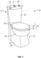
- FIG. 1 illustrates toilets according to exemplary embodiments of the present disclosure.
- FIG. 1 illustrates an exemplary embodiment of a skirted toilet 10 that includes a toilet tank 11, a pedestal 21 (or base) supporting a toilet bowl 23, a seat assembly 17 and a coupling or mounting assembly
- the seat assembly 17 includes a cover 18 and a seat ring 19 that rests on a rim 24 of the toilet bowl 23.
- the toilet tank 11 may include a reservoir 12 for storing the water used during operational (or flushing) cycles, a cover member 13 for providing selective access into the reservoir 12, and an actuator (flush mechanism) 14 that is configured to initiate an operational cycle when activated.
- the cover member 13 may include a chemical dispensing system 20.
- the cover member 13 may include an opening 16 for a lid 15. Additional, different or fewer components may be included.
- the chemistry/cleaning compounds may be delivered to specific components of the systems such as the toilet tank 11 alone or mixed with another compound or element.
- the compounds may be provided into the toilet tank 11, such as prepared within the cover member 13 introduced into the toilet for use therein.
- the chemicals/compounds can take various forms, such as liquids or solids.
- One example is in the form of phosphate beads, which may be spherical (e.g., 12.7-25.4 mm in diameter) or may have any suitable shape.
- Another example includes a shell (e.g., glass shell) that houses a chemical (e.g., phosphate) inside and is released or brought into contact with a diluent, such as through an opening.
- the concentration of the chemical may be relatively high, so that it can last over a long period of time (e.g., about one year) without having to be replaced.
- the system 20 for introducing a cleaning compound may be built into the toilet 10 or may be an add-on system that can be installed onto a traditional system and/or toilet 10 (after its manufacturing, such as an after-market system or assembly) to improve the cleanliness of the toilet 10.
- Beads may be used in the system 20 to reduce or prohibit the build-up of scale and other contaminants on the surfaces of the toilet 10.
- flow beads can be used to clean a bowl, a trap, a tank, as well as other surfaces/elements of the toilet. Accordingly, beads may break up the agglomeration of scale on the inside surfaces of the components of the toilet, such as the tank, bowl, etc.
- biofilm and other contaminants have less potential of attaching to the surfaces/scale.
- the flow beads therefore, may advantageously increase the slippery and/or sanitation of the toilet.
- beads may be utilized with any fluid line of the toilet, such as a water inlet line (e.g., line that introduces water into the toilet), inside a tank of the toilet (e.g., exposed directly or indirectly to the water in the tank), inside a valve of the toilet (e.g., fill valve, flush valve, etc.), or in other suitable ways.
- a water inlet line e.g., line that introduces water into the toilet
- a tank of the toilet e.g., exposed directly or indirectly to the water in the tank
- a valve of the toilet e.g., fill valve, flush valve, etc.
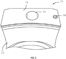
- FIG. 2 illustrates a toilet tank 11 having reservoir 12 according to an exemplary embodiment of the present disclosure.
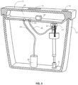
- FIG. 2 illustrates an exemplary embodiment of a toilet 10 that includes a cover member 13, a receptacle 26 (as shown in FIG. 3 ) within the cover member 13, an opening 16 of the receptacle 26, a lid 15 for the opening 16 of the cover member 13, and a flush mechanism 14.
- the cover member 2 may be provided for selective access into the reservoir 12.
- the flush mechanism 14 may be a button configured to activate when depressed (or pulled) a predetermined distance or when touched, a lever configured to activate when rotated a predetermined angular travel, or any suitable device configured to activate based upon an input manipulation by a user. Additional, different or fewer components may be included.
- the cover member 13 includes an opening 16 having a rim portion that receives a lid 15 of the system.
- the lid 15 is separate from the rim portion of the receptacle 26.
- the lid 15 may be coupled or connected to the rim portion of the receptacle 26 with a hinge. When the lid 15 is closed, the lid 15 the cover member 13 are flush with each other when the lid 15 is covering the receptacle 26.
- a fill valve 27 is in the tank 11 and supplies water to the system through an inlet line 31.
- the cover member 13 includes a fill valve line 28 with an inlet 32 at one end, an outlet 33 at the other end.
- the inlet 32 is fluidly connected to the inlet line 31 connected to the water supply (e.g., supply line from the utility). Water received through the inlet 32 can flow into the receptacle 26 of cover member 13 to mix with the cleaning compound in the chemical dispensing system 20.
- An operational cycle may start when a flush valve 30 is opened.
- Various triggering mechanism are possible such as a manual lever and flapper, or a push button and an electronic solenoid.
- the trigger corresponds to the first part of the flush cycle.
- the flush valve 30 may also include an internal chemical dispensing valve that opens the outlet line 29 to the bowl through the rim jet.
- chemical compound from the receptacle 26 is provided to the bowl.
- a siphon effect and/or gravity pulls water from the receptacle 26 into the toilet bowl 23 via a tube during the operational cycle.
- the tube may include the outlet line 29.
- the water may also pass through a rim passage into one or more rim opening that dispense the cleaning solution into the toilet bowl 23.
- the internal chemical dispensing valve may be opened after the tank 11 has been emptied into the bowl for rinsing and/or flushing. After the flush valve 30 is closed, the internal chemical dispensing valve releases the chemical compound from the receptacle 26 is provided to the tank 11 for the subsequent flush cycle. That is, when the flush valve 30 is next opened, the chemical compound in the tank 11 is released to the bowl.
- the fill valve 27 provides new water to the receptacle 26 and the chemical dispensing system 20. That is, after the tank 11 drains to the bowl 23, the tank is refilled by the fill valve 27 and at the same time or substantially the same time, fresh water is provided to the receptacle 26 where it is mixed with cleaning compound by the chemical dispensing system 20. Upon the next flush cycle, as described above, the chemical compound is dispensed into the tank 11 and/or bowl.
- the water may be replenished to the receptacle 26 under water pressure from the water supply.
- the water may be provided through a siphon effect through the water line 28.
- the chemical compound solution from the receptacle 26 may be dispensed to the tank 11 through a capillary channel. That is, the outlet line 29 may be omitted as an opening and/or a capillary channel may connect the receptacle tank 26 to the tank 11.
- a flush valve 30 causes the cleaning solution to be dispensed from the receptacle 26 into the toilet bowl 23.
- a flush trigger may include a button configured to activate the flush valve 30 mechanically through a drive mechanism (e.g., rod, pulley, lever, etc.).
- the flush trigger may alternatively be electronic such that a motor or solenoid is caused to move the flush valve in response to a button pressure or signal received from a wire or wirelessly.
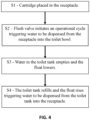
- step S3 water in the tank empties and a float of the flush valve 30 lowers (e.g., moves in a first direction).
- the water emptying from the tank may induce a siphoning of water (e.g., drain) from the receptacle 26 into the toilet bowl 23.
- FIG. 5 is an example block diagram for a controller 100 configure to operate the chemical dispensing system 20.
- the controller 100 may include a processor 300, a memory 352, and a communication interface 353 for interfacing with devices or to the internet and/or other networks 346.
- a sensor interface may be configured to receive data from the sensors described herein or data from any source.
- the controller 100 may include an integrated an indicator (e.g., display, LED, speaker, or other output devices).
- the components of the control system may communicate using bus 348.
- the control system may be connected to a workstation or another external device (e.g., control panel) and/or a database for receiving user inputs, system characteristics, durations and any of the thresholds described herein.
- the control system may include an input device 355 and/or a sensing circuit.
- sensor 356 in FIG. 5 may represent both the sensor at the toilet 10 and the corresponding circuitry at the controller 100 to communicate with the sensor.
- the sensing circuit receives sensor measurements from sensors as described above.
- the input device 355 may alternatively include one or more user inputs such as buttons, touchscreen, a keyboard, a microphone or other mechanism for calibrated any of the system characteristics, durations and any of the thresholds described herein.
- control system may include a drive unit 340 for receiving and reading non-transitory computer media 341 having instructions 342. Additional, different, or fewer components may be included.
- the processor 300 is configured to perform instructions 342 stored in memory 352 for executing the algorithms described herein.
- FIG. 6 illustrates an example flow chart for the operation of the controller 100 for the control system for the chemical dispensing system 20. Additional, different or fewer acts may be included.
- the controller 100 receives sensor data from the sensor 356.
- the sensor 356 may be mounted within the receptacle 26.
- the sensor 356 may be integrated with the outlet line 29 and/or flush valve 30.
- the sensor data describes a concentration of the chemical compound in the receptacle 26.
- the sensor 356 may alternatively include a timer that measures an amount of time since the last flush (i.e., when the flush valve 30 was actuated).
- the chemical dispensing system 20 may be reactivated after a predetermined amount of time has elapsed.
- the user input device 355 is configured to receive calibration data from the user.
- the calibration data may include a value for the target concentration of the chemical solution in the receptacle 26.
- the calibration data may specify a time of chemical or compound in the chemical dispensing unit 20.
- the calibration data may define a time interval for replenishment of the cleaning compound or other maintenance of the chemical dispensing unit 20.
- the controller 100 compares the sensor data to a threshold for a target operation of the chemical dispensing system 20.
- the target operation may be a target concentration for the chemical solution in the receptacle.
- the controller 100 (e.g., processor 300) sends a command to the chemical dispensing system 20 in response to the comparison.
- the command may cause the chemical dispensing system 20 to start and/or continue releasing the chemical into the receptacle when the concentration is below the target.
- the command may cause the chemical dispensing system 20 to stop releasing the chemical into the receptacle when the concentration is above the target.
- the controller 100 (e.g., processor 300) provides an indication of the status or operation of the chemical dispensing system 20.
- the controller 100 may send a control signal to the indicator 350, which is a light, a display, or other device configured to inform the user of the status or operation.
- the indicator 350 may communicate that the chemical dispensing system 20 is ready.
- the ready status may be represented by a green light and correspond to the determination by the controller 100 that the chemical solution is add the target concentration.
- the indicator 350 may communicate that the chemical dispensing system 20 is dispensing (i.e., not yet ready).
- the ready status may be represented by a red light and correspond to the determination by the controller 100 that the chemical solution is below the target concentration.
- the controller 100 may disable the flush actuator 14 until the chemical dispensing system 20 is ready and the indicator 350 is green.
- Memory 352 may include one or more devices (e.g., memory units, memory devices, storage devices, etc.) for storing data and/or computer code for completing and/or facilitating the various processes described in the present disclosure.
- Memory 352 may include random access memory (RAM), read-only memory (ROM), hard drive storage, temporary storage, non-volatile memory, flash memory, optical memory, or any other suitable memory for storing software objects and/or computer instructions.
- RAM random access memory
- ROM read-only memory
- ROM read-only memory
- Memory 352 may include database components, object code components, script components, or any other type of information structure for supporting the various activities and information structures described in the present disclosure.
- Memory 352 may be communicably connected to processor 300 via a processing circuit and may include computer code for executing (e.g., by processor 300) one or more processes described herein.
- the communication interface 353 may include any operable connection.
- An operable connection may be one in which signals, physical communications, and/or logical communications may be sent and/or received.
- An operable connection may include a physical interface, an electrical interface, and/or a data interface.
- the communication interface 353 may be connected to a network.
- the network may include wired networks (e.g., Ethernet), wireless networks, or combinations thereof.
- the wireless network may be a cellular telephone network, an 802.11, 802.16, 802.20, or WiMax network, a Bluetooth pairing of devices, or a Bluetooth mesh network.
- the network may be a public network, such as the Internet, a private network, such as an intranet, or combinations thereof, and may utilize a variety of networking protocols now available or later developed including, but not limited to TCP/IP based networking protocols.
- While the computer-readable medium (e.g., memory 352) is shown to be a single medium, the term “computer-readable medium” includes a single medium or multiple media, such as a centralized or distributed database, and/or associated caches and servers that store one or more sets of instructions.
- the term “computer-readable medium” shall also include any medium that is capable of storing, encoding or carrying a set of instructions for execution by a processor or that cause a computer system to perform any one or more of the methods or operations disclosed herein.
- the computer-readable medium can include a solid-state memory such as a memory card or other package that houses one or more non-volatile read-only memories. Further, the computer-readable medium can be a random access memory or other volatile re-writable memory. Additionally, the computer-readable medium can include a magnetooptical or optical medium, such as a disk or tapes or other storage device to capture carrier wave signals such as a signal communicated over a transmission medium. A digital file attachment to an e-mail or other self-contained information archive or set of archives may be considered a distribution medium that is a tangible storage medium.
- the disclosure is considered to include any one or more of a computer-readable medium or a distribution medium and other equivalents and successor media, in which data or instructions may be stored.
- the computer-readable medium may be non-transitory, which includes all tangible computer-readable media.
- inventions of the disclosure may be referred to herein, individually and/or collectively, by the term "invention" merely for convenience and without intending to voluntarily limit the scope of this application to any particular invention or inventive concept.
- inventions may be referred to herein, individually and/or collectively, by the term "invention" merely for convenience and without intending to voluntarily limit the scope of this application to any particular invention or inventive concept.
- specific embodiments have been illustrated and described herein, it should be appreciated that any subsequent arrangement designed to achieve the same or similar purpose may be substituted for the specific embodiments shown.
- This disclosure is intended to cover any and all subsequent adaptations or variations of various embodiments. Combinations of the above embodiments, and other embodiments not specifically described herein, will be apparent to those of skill in the art upon reviewing the description.
- Coupled means the joining of two members directly or indirectly to one another. Such joining may be stationary (e.g., permanent or fixed) or moveable (e.g., removable or releasable). Such joining may be achieved with the two members coupled directly to each other, with the two members coupled to each other using a separate intervening member and any additional intermediate members coupled with one another, or with the two members coupled to each other using an intervening member that is integrally formed as a single unitary body with one of the two members.
- Coupled or variations thereof are modified by an additional term (e.g., directly coupled)
- the generic definition of “coupled” provided above is modified by the plain language meaning of the additional term (e.g., "directly coupled” means the joining of two members without any separate intervening member), resulting in a narrower definition than the generic definition of "coupled” provided above.
- Such coupling may be mechanical, electrical, or fluidic.
Landscapes
- Health & Medical Sciences (AREA)
- Public Health (AREA)
- Engineering & Computer Science (AREA)
- Life Sciences & Earth Sciences (AREA)
- Hydrology & Water Resources (AREA)
- Water Supply & Treatment (AREA)
- Epidemiology (AREA)
- Mechanical Engineering (AREA)
- Aviation & Aerospace Engineering (AREA)
- Bidet-Like Cleaning Device And Other Flush Toilet Accessories (AREA)
- Sanitary Device For Flush Toilet (AREA)
Applications Claiming Priority (2)
| Application Number | Priority Date | Filing Date | Title |
|---|---|---|---|
| US202363526799P | 2023-07-14 | 2023-07-14 | |
| US18/761,212 US20250019953A1 (en) | 2023-07-14 | 2024-07-01 | Cover system for a toilet tank |
Publications (2)
| Publication Number | Publication Date |
|---|---|
| EP4491813A2 true EP4491813A2 (de) | 2025-01-15 |
| EP4491813A3 EP4491813A3 (de) | 2025-02-26 |
Family
ID=91923917
Family Applications (1)
| Application Number | Title | Priority Date | Filing Date |
|---|---|---|---|
| EP24188125.9A Pending EP4491813A3 (de) | 2023-07-14 | 2024-07-11 | Abdecksystem für einen toilettentank |
Country Status (3)
| Country | Link |
|---|---|
| US (1) | US20250019953A1 (de) |
| EP (1) | EP4491813A3 (de) |
| CN (1) | CN119308389A (de) |
Family Cites Families (5)
| Publication number | Priority date | Publication date | Assignee | Title |
|---|---|---|---|---|
| DE3013063A1 (de) * | 1980-04-03 | 1981-10-15 | Peter K. 6540 Simmern Kauder | Toilettenwasserspuelkasten mit hohlraumdeckel |
| HK1223137A1 (zh) * | 2013-07-15 | 2017-07-21 | As 知识产权控股有限公司 | 自清洗马桶组件和系统 |
| US10760255B2 (en) * | 2013-07-15 | 2020-09-01 | As America, Inc. | Self cleaning toilet assembly and system |
| EP3341533B1 (de) * | 2015-08-24 | 2022-12-07 | Kohler Co. | Toilette mit abgabevorrichtung für chemische lösung |
| IL255623B (en) * | 2017-11-13 | 2020-10-29 | Dan El Eglick | Top cover for toilet tank |
-
2024
- 2024-07-01 US US18/761,212 patent/US20250019953A1/en active Pending
- 2024-07-11 EP EP24188125.9A patent/EP4491813A3/de active Pending
- 2024-07-15 CN CN202410941942.3A patent/CN119308389A/zh active Pending
Also Published As
| Publication number | Publication date |
|---|---|
| US20250019953A1 (en) | 2025-01-16 |
| CN119308389A (zh) | 2025-01-14 |
| EP4491813A3 (de) | 2025-02-26 |
Similar Documents
| Publication | Publication Date | Title |
|---|---|---|
| US20210207354A1 (en) | Clean toilet and accessories | |
| CA2254424C (en) | Toilet cleaner controller device | |
| US8095997B2 (en) | Modular cartridge based liquid dispenser system for toilets and bidets | |
| DE102007040323A1 (de) | WC-Spüler mit einstellbarer Wirkstoffabgabemenge | |
| DE102007040327A1 (de) | WC-Spüler mit zeitversetzter Wirkstofffreisetzung | |
| CA2677164A1 (en) | Method and control system for processing greywater | |
| RU2388873C2 (ru) | Дозирующее устройство для туалета | |
| US20100180365A1 (en) | Toilet disinfectant dispensing system and method therefor | |
| EP4491813A2 (de) | Abdecksystem für einen toilettentank | |
| US20220243443A1 (en) | Centralized clean water system | |
| KR101908846B1 (ko) | 세정액 공급 장치 및 이를 포함하는 변기 수조 | |
| GB2517131A (en) | Dispenser for use with sanitary appliances | |
| US20220381022A1 (en) | Fluid dispensing system | |
| US20200392712A1 (en) | Dosing system and method for dispensing at least one chemical composition inside the tank of a toilet | |
| US7047574B2 (en) | System and method for automatically varying a volume of a liquid held by a toilet receptacle | |
| US12590449B2 (en) | Toilet | |
| JP2013096187A (ja) | 補給水供給装置、この補給水供給装置を備えた洗浄水タンク装置、及び、この洗浄水タンク装置が適用された水洗大便器 | |
| WO2004016869A1 (en) | Apparatus for the dispensing of a liquid, adapted to be placed in a volume of liquid with fluctuating liquid level, particularly adapted for metered disposal of chemicals to a cistern | |
| US20250129584A1 (en) | Detergent sustained-release device and water-using apparatus | |
| CN205224220U (zh) | 改进型马桶 | |
| JP2007314957A (ja) | 洋風便器装置 | |
| US7549181B1 (en) | Toilet lid apparatus | |
| RU209951U1 (ru) | Туалетный бачок | |
| JP2016030994A (ja) | 洗浄水タンク装置および水洗大便器 | |
| CN115298398A (zh) | 一种冲洗水供给装置 |
Legal Events
| Date | Code | Title | Description |
|---|---|---|---|
| PUAI | Public reference made under article 153(3) epc to a published international application that has entered the european phase |
Free format text: ORIGINAL CODE: 0009012 |
|
| STAA | Information on the status of an ep patent application or granted ep patent |
Free format text: STATUS: THE APPLICATION HAS BEEN PUBLISHED |
|
| AK | Designated contracting states |
Kind code of ref document: A2 Designated state(s): AL AT BE BG CH CY CZ DE DK EE ES FI FR GB GR HR HU IE IS IT LI LT LU LV MC ME MK MT NL NO PL PT RO RS SE SI SK SM TR |
|
| RIN1 | Information on inventor provided before grant (corrected) |
Inventor name: GARRELS, CLAYTON C. Inventor name: KURU, WILLIAM C. |
|
| PUAL | Search report despatched |
Free format text: ORIGINAL CODE: 0009013 |
|
| AK | Designated contracting states |
Kind code of ref document: A3 Designated state(s): AL AT BE BG CH CY CZ DE DK EE ES FI FR GB GR HR HU IE IS IT LI LT LU LV MC ME MK MT NL NO PL PT RO RS SE SI SK SM TR |
|
| RIC1 | Information provided on ipc code assigned before grant |
Ipc: E03D 1/34 20060101ALI20250121BHEP Ipc: E03D 1/32 20060101ALI20250121BHEP Ipc: E03D 1/012 20060101ALI20250121BHEP Ipc: E03D 9/03 20060101AFI20250121BHEP |
|
| STAA | Information on the status of an ep patent application or granted ep patent |
Free format text: STATUS: REQUEST FOR EXAMINATION WAS MADE |
|
| 17P | Request for examination filed |
Effective date: 20250819 |