EP4491810A1 - Improved hydraulic arrangement for a work machine and work machine comprising such hydraulic arrangement - Google Patents
Improved hydraulic arrangement for a work machine and work machine comprising such hydraulic arrangement Download PDFInfo
- Publication number
- EP4491810A1 EP4491810A1 EP24188431.1A EP24188431A EP4491810A1 EP 4491810 A1 EP4491810 A1 EP 4491810A1 EP 24188431 A EP24188431 A EP 24188431A EP 4491810 A1 EP4491810 A1 EP 4491810A1
- Authority
- EP
- European Patent Office
- Prior art keywords
- hydraulic
- chamber
- actuator
- arrangement
- fluid
- Prior art date
- Legal status (The legal status is an assumption and is not a legal conclusion. Google has not performed a legal analysis and makes no representation as to the accuracy of the status listed.)
- Pending
Links
Images


Classifications
-
- E—FIXED CONSTRUCTIONS
- E02—HYDRAULIC ENGINEERING; FOUNDATIONS; SOIL SHIFTING
- E02F—DREDGING; SOIL-SHIFTING
- E02F9/00—Component parts of dredgers or soil-shifting machines, not restricted to one of the kinds covered by groups E02F3/00 - E02F7/00
- E02F9/20—Drives; Control devices
- E02F9/22—Hydraulic or pneumatic drives
- E02F9/2221—Control of flow rate; Load sensing arrangements
- E02F9/2225—Control of flow rate; Load sensing arrangements using pressure-compensating valves
- E02F9/2228—Control of flow rate; Load sensing arrangements using pressure-compensating valves including an electronic controller
-
- E—FIXED CONSTRUCTIONS
- E02—HYDRAULIC ENGINEERING; FOUNDATIONS; SOIL SHIFTING
- E02F—DREDGING; SOIL-SHIFTING
- E02F9/00—Component parts of dredgers or soil-shifting machines, not restricted to one of the kinds covered by groups E02F3/00 - E02F7/00
- E02F9/20—Drives; Control devices
- E02F9/22—Hydraulic or pneumatic drives
- E02F9/2217—Hydraulic or pneumatic drives with energy recovery arrangements, e.g. using accumulators, flywheels
-
- E—FIXED CONSTRUCTIONS
- E02—HYDRAULIC ENGINEERING; FOUNDATIONS; SOIL SHIFTING
- E02F—DREDGING; SOIL-SHIFTING
- E02F9/00—Component parts of dredgers or soil-shifting machines, not restricted to one of the kinds covered by groups E02F3/00 - E02F7/00
- E02F9/20—Drives; Control devices
- E02F9/22—Hydraulic or pneumatic drives
- E02F9/2221—Control of flow rate; Load sensing arrangements
- E02F9/2232—Control of flow rate; Load sensing arrangements using one or more variable displacement pumps
- E02F9/2235—Control of flow rate; Load sensing arrangements using one or more variable displacement pumps including an electronic controller
-
- E—FIXED CONSTRUCTIONS
- E02—HYDRAULIC ENGINEERING; FOUNDATIONS; SOIL SHIFTING
- E02F—DREDGING; SOIL-SHIFTING
- E02F9/00—Component parts of dredgers or soil-shifting machines, not restricted to one of the kinds covered by groups E02F3/00 - E02F7/00
- E02F9/20—Drives; Control devices
- E02F9/22—Hydraulic or pneumatic drives
- E02F9/2221—Control of flow rate; Load sensing arrangements
- E02F9/2239—Control of flow rate; Load sensing arrangements using two or more pumps with cross-assistance
- E02F9/2242—Control of flow rate; Load sensing arrangements using two or more pumps with cross-assistance including an electronic controller
-
- F—MECHANICAL ENGINEERING; LIGHTING; HEATING; WEAPONS; BLASTING
- F15—FLUID-PRESSURE ACTUATORS; HYDRAULICS OR PNEUMATICS IN GENERAL
- F15B—SYSTEMS ACTING BY MEANS OF FLUIDS IN GENERAL; FLUID-PRESSURE ACTUATORS, e.g. SERVOMOTORS; DETAILS OF FLUID-PRESSURE SYSTEMS, NOT OTHERWISE PROVIDED FOR
- F15B11/00—Servomotor systems without provision for follow-up action ; Circuits therefor
- F15B11/02—Systems essentially incorporating special features for controlling the speed or the actuating force of an output member
- F15B11/028—Systems essentially incorporating special features for controlling the speed or the actuating force of an output member for controlling the actuating force
- F15B11/032—Systems essentially incorporating special features for controlling the speed or the actuating force of an output member for controlling the actuating force by means of fluid-pressure converters
-
- F—MECHANICAL ENGINEERING; LIGHTING; HEATING; WEAPONS; BLASTING
- F15—FLUID-PRESSURE ACTUATORS; HYDRAULICS OR PNEUMATICS IN GENERAL
- F15B—SYSTEMS ACTING BY MEANS OF FLUIDS IN GENERAL; FLUID-PRESSURE ACTUATORS, e.g. SERVOMOTORS; DETAILS OF FLUID-PRESSURE SYSTEMS, NOT OTHERWISE PROVIDED FOR
- F15B11/00—Servomotor systems without provision for follow-up action ; Circuits therefor
- F15B11/16—Servomotor systems without provision for follow-up action ; Circuits therefor with two or more servomotors
- F15B11/17—Servomotor systems without provision for follow-up action ; Circuits therefor with two or more servomotors using two or more pumps
-
- F—MECHANICAL ENGINEERING; LIGHTING; HEATING; WEAPONS; BLASTING
- F15—FLUID-PRESSURE ACTUATORS; HYDRAULICS OR PNEUMATICS IN GENERAL
- F15B—SYSTEMS ACTING BY MEANS OF FLUIDS IN GENERAL; FLUID-PRESSURE ACTUATORS, e.g. SERVOMOTORS; DETAILS OF FLUID-PRESSURE SYSTEMS, NOT OTHERWISE PROVIDED FOR
- F15B2211/00—Circuits for servomotor systems
- F15B2211/20—Fluid pressure source, e.g. accumulator or variable axial piston pump
- F15B2211/205—Systems with pumps
- F15B2211/20576—Systems with pumps with multiple pumps
- F15B2211/20592—Combinations of pumps for supplying high and low pressure
-
- F—MECHANICAL ENGINEERING; LIGHTING; HEATING; WEAPONS; BLASTING
- F15—FLUID-PRESSURE ACTUATORS; HYDRAULICS OR PNEUMATICS IN GENERAL
- F15B—SYSTEMS ACTING BY MEANS OF FLUIDS IN GENERAL; FLUID-PRESSURE ACTUATORS, e.g. SERVOMOTORS; DETAILS OF FLUID-PRESSURE SYSTEMS, NOT OTHERWISE PROVIDED FOR
- F15B2211/00—Circuits for servomotor systems
- F15B2211/20—Fluid pressure source, e.g. accumulator or variable axial piston pump
- F15B2211/21—Systems with pressure sources other than pumps, e.g. with a pyrotechnical charge
- F15B2211/212—Systems with pressure sources other than pumps, e.g. with a pyrotechnical charge the pressure sources being accumulators
-
- F—MECHANICAL ENGINEERING; LIGHTING; HEATING; WEAPONS; BLASTING
- F15—FLUID-PRESSURE ACTUATORS; HYDRAULICS OR PNEUMATICS IN GENERAL
- F15B—SYSTEMS ACTING BY MEANS OF FLUIDS IN GENERAL; FLUID-PRESSURE ACTUATORS, e.g. SERVOMOTORS; DETAILS OF FLUID-PRESSURE SYSTEMS, NOT OTHERWISE PROVIDED FOR
- F15B2211/00—Circuits for servomotor systems
- F15B2211/20—Fluid pressure source, e.g. accumulator or variable axial piston pump
- F15B2211/21—Systems with pressure sources other than pumps, e.g. with a pyrotechnical charge
- F15B2211/216—Systems with pressure sources other than pumps, e.g. with a pyrotechnical charge the pressure sources being pneumatic-to-hydraulic converters
-
- F—MECHANICAL ENGINEERING; LIGHTING; HEATING; WEAPONS; BLASTING
- F15—FLUID-PRESSURE ACTUATORS; HYDRAULICS OR PNEUMATICS IN GENERAL
- F15B—SYSTEMS ACTING BY MEANS OF FLUIDS IN GENERAL; FLUID-PRESSURE ACTUATORS, e.g. SERVOMOTORS; DETAILS OF FLUID-PRESSURE SYSTEMS, NOT OTHERWISE PROVIDED FOR
- F15B2211/00—Circuits for servomotor systems
- F15B2211/30—Directional control
- F15B2211/305—Directional control characterised by the type of valves
- F15B2211/3056—Assemblies of multiple valves
- F15B2211/30565—Assemblies of multiple valves having multiple valves for a single output member, e.g. for creating higher valve function by use of multiple valves like two 2/2-valves replacing a 5/3-valve
- F15B2211/30575—Assemblies of multiple valves having multiple valves for a single output member, e.g. for creating higher valve function by use of multiple valves like two 2/2-valves replacing a 5/3-valve in a Wheatstone Bridge arrangement (also half bridges)
-
- F—MECHANICAL ENGINEERING; LIGHTING; HEATING; WEAPONS; BLASTING
- F15—FLUID-PRESSURE ACTUATORS; HYDRAULICS OR PNEUMATICS IN GENERAL
- F15B—SYSTEMS ACTING BY MEANS OF FLUIDS IN GENERAL; FLUID-PRESSURE ACTUATORS, e.g. SERVOMOTORS; DETAILS OF FLUID-PRESSURE SYSTEMS, NOT OTHERWISE PROVIDED FOR
- F15B2211/00—Circuits for servomotor systems
- F15B2211/30—Directional control
- F15B2211/31—Directional control characterised by the positions of the valve element
- F15B2211/3138—Directional control characterised by the positions of the valve element the positions being discrete
-
- F—MECHANICAL ENGINEERING; LIGHTING; HEATING; WEAPONS; BLASTING
- F15—FLUID-PRESSURE ACTUATORS; HYDRAULICS OR PNEUMATICS IN GENERAL
- F15B—SYSTEMS ACTING BY MEANS OF FLUIDS IN GENERAL; FLUID-PRESSURE ACTUATORS, e.g. SERVOMOTORS; DETAILS OF FLUID-PRESSURE SYSTEMS, NOT OTHERWISE PROVIDED FOR
- F15B2211/00—Circuits for servomotor systems
- F15B2211/30—Directional control
- F15B2211/365—Directional control combined with flow control and pressure control
-
- F—MECHANICAL ENGINEERING; LIGHTING; HEATING; WEAPONS; BLASTING
- F15—FLUID-PRESSURE ACTUATORS; HYDRAULICS OR PNEUMATICS IN GENERAL
- F15B—SYSTEMS ACTING BY MEANS OF FLUIDS IN GENERAL; FLUID-PRESSURE ACTUATORS, e.g. SERVOMOTORS; DETAILS OF FLUID-PRESSURE SYSTEMS, NOT OTHERWISE PROVIDED FOR
- F15B2211/00—Circuits for servomotor systems
- F15B2211/70—Output members, e.g. hydraulic motors or cylinders or control therefor
- F15B2211/705—Output members, e.g. hydraulic motors or cylinders or control therefor characterised by the type of output members or actuators
- F15B2211/7051—Linear output members
- F15B2211/7053—Double-acting output members
-
- F—MECHANICAL ENGINEERING; LIGHTING; HEATING; WEAPONS; BLASTING
- F15—FLUID-PRESSURE ACTUATORS; HYDRAULICS OR PNEUMATICS IN GENERAL
- F15B—SYSTEMS ACTING BY MEANS OF FLUIDS IN GENERAL; FLUID-PRESSURE ACTUATORS, e.g. SERVOMOTORS; DETAILS OF FLUID-PRESSURE SYSTEMS, NOT OTHERWISE PROVIDED FOR
- F15B2211/00—Circuits for servomotor systems
- F15B2211/70—Output members, e.g. hydraulic motors or cylinders or control therefor
- F15B2211/76—Control of force or torque of the output member
Definitions
- the present invention relates to a hydraulic arrangement for a work machine, in particular for an earth-moving machine such as an excavator, a digger, a mechanical shovel or the like.
- the present invention further relates to a work machine comprising such a hydraulic arrangement.
- such hydraulic actuated work implement usually comprises: a boom rotatably carried by the body of the work machine; a stick or dipper or arm rotatably carried by the boom; a bucket or similar work attachment rotatably carried by the arm; and a plurality of hydraulic actuators adapted to rotate the boom, the arm, and the bucket with respect to their hinge points.
- Such work machines comprise a hydraulic circuit, which is configured to provide pressurized hydraulic fluid towards at least one of the aforementioned hydraulic actuators, in order to operate this latter.
- variable displacement linear actuators fluidly connected to a source of pressurized hydraulic fluid by means of common pressure rails (CPR) and a set of logic on-off hydraulic valve configured to selectively fluidly connect the source of pressurized hydraulic fluid with the variable displacement linear actuator.
- CPR common pressure rails
- FIG. 1 An example of such a simplified hydraulic circuit is schematically represented in Figure 1 and is denoted as a whole with reference number 100.
- Hydraulic circuit 100 comprises a hydraulic pump 110, which is carried by an internal combustion engine 120 of the work machine and is configured to suck hydraulic fluid from a tank 130 and to provide at outlet a pressured flow of such hydraulic fluid.
- Hydraulic pump 110 is configured to be fluidly connected to at least one hydraulic actuator 140, in order to feed to the same hydraulic actuator 140 the hydraulic fluid provided at outlet.
- Hydraulic actuator 140 may be, for instance, the boom actuator, the arm actuator or the bucket actuator of the aforementioned work machine.
- hydraulic circuit 100 comprises a plurality of hydraulic lines, also referred to as hydraulic pressure rails, fluidly connecting the hydraulic pump 110 with the hydraulic cylinder 140.
- hydraulic circuit 100 comprises three distinct pressure rails 150, 160 and 170 fluidly connecting the hydraulic pump 110 with the hydraulic actuator 140.
- each pressure rails 150, 160 and 170 is selectively connectable to the chambers A, B, C and D of hydraulic actuator 140.
- each pressure rail 150, 160 and 170 is provided with its own hydraulic accumulator 155, 165 and 175, which is configured to accumulate hydraulic fluid at a predetermined pressure level, in order to set the pressure level of the fluid flowing through the respective pressure rail 150, 160 and 170.
- hydraulic circuit 100 may be provided with a high-pressure rail 150, a medium-pressure rail 160 and a low-pressure rail 170.
- the hydraulic circuit 100 comprises a valve arrangement 180, which is configured to allow selectively fluidly connecting each pressure rail 150, 160 and 170 to each chamber A, B, C and D of the hydraulic cylinder 140.
- valve arrangement 180 for each chamber A, B, C and D, comprises three logic/discrete valves, each of which is operatively interposed between the respective chamber port and the respective constant pressure rail 150, 160 and 170.
- # F hyd is the number of discrete values of the hydraulic force F hyd acting on the hydraulic cylinder 140 piston
- # rails is the number of rails present in the common pressure rails architecture
- # chamber is the number of chambers of the multi-chamber cylinders.
- the number of discrete values of the hydraulic force F hyd acting on the hydraulic cylinder 140 is equal to 3 4 , i.e. 81.
- asymmetrical multi-chambers hydraulic cylinders are difficult to design, really expensive and unreliable, with all the obvious drawbacks that this entails.
- the cost of the asymmetrical multi-chambers hydraulic cylinders has a non-negligible impact on the overall cost of the work machine.
- valve arrangement 180 is arranged close to the respective hydraulic cylinder 140 and is carried directly by the hydraulically actuated arm of the work machine. This drastically increases the weight and the inertia of the hydraulically actuated arm and reduces the lifting capacity of the work machine, with the obvious drawbacks that this entails.
- Aim of the present invention is to satisfy the above-mentioned need in an optimized and cost-effective manner.
- number 1 denotes, as a whole, a work machine, in particular an earth-moving machine such as an excavator, a digger, a mechanical shovel or the like.
- Work machine 1 comprises a body 2 movable on the ground via ground engaging wheels or tracks (not illustrated).
- body 2 preferably comprises: a lower frame or undercarriage (not illustrated), which carries the ground engaging wheels or tracks to allow motion of body 2 with respect to the ground; and an upper frame (not illustrated) or superstructure, which is carried in a rotatable manner by lower frame preferably about a rotation axis orthogonal to the advancing plane of work machine 1, i.e. orthogonal to the ground.
- work machine preferably comprises an internal combustion engine 4, which is configured to provide torque to allow motion of the work machine 2, for instance by driving a hydraulic pump, which in turn is fluidly connected to hydraulic motors that drive in rotation the ground engaging wheels or tracks.
- work machine 1 comprises a hydraulically actuated work implement 6, which is carried by body 2 and is configured to perform multiple earth moving operations, such as digging, handling earth or gravel, loading trucks and/or similar operations.
- work implement 6 is rotatably carried by the upper frame of work machine 1.
- the hydraulically actuated work implement 6 preferably comprises: a boom rotatably carried by the body 2; a stick or arm or dipper rotatably carried by the boom; and a bucket and/or other similar tools rotatably carried by the arm.
- work machine 1 preferably comprises one or more hydraulic actuators 7, which are configured to operate the hydraulically actuated work implement 6.
- hydraulic lines 21 of hydraulic circuit are selectively connectable to hydraulic actuator 7, in particular to both chambers 10a and 10b of hydraulic actuator 7.
- hydraulic circuit 20 comprises at least two lines 21, which are arranged in parallel to each other and are adapted to fluidly connect the source of pressurized fluid with hydraulic actuator 7.
- the first one between the two lines 21 is connected to the source of pressurized hydraulic fluid, while the second is preferably connected to tank 18.
- the first one between lines 21 will define a high-pressure line and the other one between lines 21 will define a low-pressure line.
- hydraulic circuit comprises at least three lines 21a, 21b and 21c arranged in parallel to each other.
- Line 21a is preferably connected to the outlet of hydraulic pump 17a
- line 21b is preferably connected to the outlet of hydraulic pump 17b
- line 21c is preferably connected to tank 18.
- hydraulic circuit 20 preferably comprises at least one hydraulic accumulator 22, which is fluidly connected to the first one between the two lines 21.
- hydraulic circuit 20 preferably comprises two hydraulic accumulators 22a and 22b respectively fluidly connected to lines 21a and 21b.
- hydraulic circuit 20 may comprise two pressure relief valves 24, which are operatively connected to lines 21a and 21b.
- hydraulic arrangement 14 further comprises a control valve arrangement 26, which is fluidly interposed between hydraulic circuit 20 and hydraulic actuator 7 and is configured to regulate the pressurized hydraulic fluid fed toward the same hydraulic actuator 7.
- control valve arrangement 26 is configured to allow to selectively fluidly connect the chambers 10a and 10b of hydraulic actuator 7 with lines 21 of hydraulic circuit 20.
- control valve arrangement 26 is preferably carried by body 2.
- Control valve arrangement 26 is preferably configured to be fluidly connected to hydraulic actuator 7 via hydraulic lines 15.
- control valve arrangement 26 comprises a second valve set 28, which is operatively interposed between the hydraulic circuit 20 and the second chamber 10b of hydraulic actuator 7.
- Valve sets 27 and 28 are preferably configured to be fluidly connected to the respective chambers 10a and 10b of hydraulic actuator 7 respectively via hydraulic line 15a and hydraulic line 15b.
- valves or first valve set 27 and second valve set 28 are solenoid-controlled two-way two-position valves, in particular solenoid-controlled two-way two-position on-off valves, which are operable independently to each other and are operable between an open position and a closed position.
- valve sets 27 and 28 preferably each comprise three valves 27a-27c and 28a-28c, which are fluidly interposed respectively between high-pressure line 21a, medium-pressure line 21b and low-pressure line 21c and the respective chamber 10a and 10b of hydraulic actuator 7.
- each chamber 10a and 10b of hydraulic actuator 7, in operation may assume at least three different pressure levels depending on the operation of valve sets 27 and 28.
- hydraulic arrangement 14 preferably comprises one or more pressure multiplier or pressure amplifier or pressure booster hydraulic cylinders 30, which are operatively interposed between control valve arrangement 26 and hydraulic actuator 7 and are configured to selectively increase the pressure of the hydraulic fluid provided towards hydraulic actuator 7.
- the one or more pressure multiplier hydraulic cylinders 30 are carried by body 2.
- the one or more pressure multiplier hydraulic cylinders 30 are each preferably adapted to be fluidly connected to hydraulic actuator 7 via hydraulic lines 15.
- the one or more pressure multiplier hydraulic cylinders 30 preferably comprises single acting cylinders.
- the one or more pressure multiplier hydraulic cylinders 30 comprises a housing 31, which accommodates in a fluid tight and sliding manner a piston 32.
- the piston 32 defines a first chamber and a second chamber opposite to each other within the housing.
- the first chamber has an area which is larger than the area of the second chamber, in particular the area of the first chamber may be twice the area of the second chamber.
- the first chamber, i.e. the larger chamber, of pressure multiplier hydraulic cylinder is fluidly connected to hydraulic circuit 20 and the second chamber, i.e. the smaller chamber is fluidly connected to hydraulic actuator 7, in order to be able to increase the pressure of the hydraulic fluid fed towards hydraulic actuator 7.
- the pressure of the fluid fed towards the chambers 10a and 10b of hydraulic actuator by pressure multiplier hydraulic cylinder 30 is equal to the pressure of the fluid received by pressure multiplier hydraulic cylinder 30 from one of the lines 21, multiplied by the pressure multiplication factor, i.e. by the area ratio, of the same pressure multiplier hydraulic cylinder 30.
Landscapes
- Engineering & Computer Science (AREA)
- General Engineering & Computer Science (AREA)
- Physics & Mathematics (AREA)
- Fluid Mechanics (AREA)
- Mining & Mineral Resources (AREA)
- Civil Engineering (AREA)
- Structural Engineering (AREA)
- Mechanical Engineering (AREA)
- Fluid-Pressure Circuits (AREA)
Abstract
Description
- The present invention relates to a hydraulic arrangement for a work machine, in particular for an earth-moving machine such as an excavator, a digger, a mechanical shovel or the like. The present invention further relates to a work machine comprising such a hydraulic arrangement.
- The present invention finds its preferred, although not exclusive, application in a hydraulic arrangement provided with a common pressure rails (CPR) configuration and adapted to control at least one hydraulic actuator of a hydraulically actuated arm of a work machine, in particular an excavator. Reference will be made to this application by way of the example below, without however losing in generality.
- As is known, work machines such as excavators, diggers or the like are provided with a hydraulically actuated work implement carried by a body of the work machine and configured to perform multiple earth-moving operations.
- In particular, such hydraulic actuated work implement usually comprises: a boom rotatably carried by the body of the work machine; a stick or dipper or arm rotatably carried by the boom; a bucket or similar work attachment rotatably carried by the arm; and a plurality of hydraulic actuators adapted to rotate the boom, the arm, and the bucket with respect to their hinge points.
- In addition, such work machines comprise a hydraulic circuit, which is configured to provide pressurized hydraulic fluid towards at least one of the aforementioned hydraulic actuators, in order to operate this latter.
- Traditionally, such hydraulic circuit comprises a source of pressurized hydraulic fluid and directional proportional control valves configured to throttle the flow of hydraulic fluid provided to each hydraulic actuator, to control its operation. This allows a precise control of the operation of each hydraulic actuator, but unfortunately results in a great deal of hydraulic fluid routed back to tank, with the waste in energy that this entails.
- To reduce waste of energy and allow some energy recovery, some manufacturer recently developed hydraulic circuits including variable displacement linear actuators fluidly connected to a source of pressurized hydraulic fluid by means of common pressure rails (CPR) and a set of logic on-off hydraulic valve configured to selectively fluidly connect the source of pressurized hydraulic fluid with the variable displacement linear actuator.
- An example of such a simplified hydraulic circuit is schematically represented in
Figure 1 and is denoted as a whole withreference number 100. -
Hydraulic circuit 100 comprises ahydraulic pump 110, which is carried by aninternal combustion engine 120 of the work machine and is configured to suck hydraulic fluid from atank 130 and to provide at outlet a pressured flow of such hydraulic fluid. -
Hydraulic pump 110 is configured to be fluidly connected to at least onehydraulic actuator 140, in order to feed to the samehydraulic actuator 140 the hydraulic fluid provided at outlet.Hydraulic actuator 140 may be, for instance, the boom actuator, the arm actuator or the bucket actuator of the aforementioned work machine. -
Hydraulic actuator 140 is a double-acting asymmetrical multi-chamber hydraulic cylinder, in particular a double-acting asymmetrical four-chamber hydraulic cylinder.Hydraulic actuator 140 comprises two chambers A and B configured to contain pressurized hydraulic fluid to exert forces on the piston of theactuator 140 along a first direction, and two chambers C and D configured to contain pressurized hydraulic fluid to exert forces on the piston along a second direction opposite to the first one. - Therefore, the resulting hydraulic force Fhyd acting on the piston of the hydraulic cylinder will follow the following formula:

- In addition,
hydraulic circuit 100 comprises a plurality of hydraulic lines, also referred to as hydraulic pressure rails, fluidly connecting thehydraulic pump 110 with thehydraulic cylinder 140. - With reference to the example illustrated in
Figure 1 ,hydraulic circuit 100 comprises threedistinct pressure rails hydraulic pump 110 with thehydraulic actuator 140. In particular, eachpressure rails hydraulic actuator 140. - In addition, each
pressure rail hydraulic accumulator respective pressure rail - In particular, the pressure levels within
hydraulic accumulator pressure rails hydraulic circuit 100 may be provided with a high-pressure rail 150, a medium-pressure rail 160 and a low-pressure rail 170. - In addition, the
hydraulic circuit 100 comprises avalve arrangement 180, which is configured to allow selectively fluidly connecting eachpressure rail hydraulic cylinder 140. - In particular,
valve arrangement 180, for each chamber A, B, C and D, comprises three logic/discrete valves, each of which is operatively interposed between the respective chamber port and the respectiveconstant pressure rail - Therefore, being connected to the
pressure lines hydraulic cylinder 140 piston will be discrete. - In particular, the number of discrete values of the hydraulic force Fhyd acting on the
hydraulic cylinder 140 piston can be calculated according to following formula
- Wherein # F
hyd is the number of discrete values of the hydraulic force Fhyd acting on thehydraulic cylinder 140 piston, # rails is the number of rails present in the common pressure rails architecture and #chamber is the number of chambers of the multi-chamber cylinders. - In the example illustrated in
Figure 1 , the number of discrete values of the hydraulic force Fhyd acting on thehydraulic cylinder 140 is equal to 34, i.e. 81. - Although the above hydraulic architecture allows to reduce waste of energy and allows some energy recovery by accumulating pressurized hydraulic fluid within the hydraulic accumulators during deceleration of the work machine arm, the same hydraulic architecture still poses several drawbacks and there is still plenty of room for improvements.
- In particular, asymmetrical multi-chambers hydraulic cylinders are difficult to design, really expensive and unreliable, with all the obvious drawbacks that this entails. In particular, the cost of the asymmetrical multi-chambers hydraulic cylinders has a non-negligible impact on the overall cost of the work machine.
- Furthermore, it is really cumbersome to provide multi-chambers hydraulic cylinders provided with a high number of different chambers, in particular more than four. This unfortunately strongly limits the number of discrete force level available and so the resolution of the
hydraulic circuit 100. - In addition, to avoid multiplication of flexible hoses on the excavator arm and therefore to reduce the risks of failures, the
valve arrangement 180 is arranged close to the respectivehydraulic cylinder 140 and is carried directly by the hydraulically actuated arm of the work machine. This drastically increases the weight and the inertia of the hydraulically actuated arm and reduces the lifting capacity of the work machine, with the obvious drawbacks that this entails. - In view of the above, the need is felt to provide an improved hydraulic arrangement for a work machine able to overcome the aforementioned drawbacks.
- Aim of the present invention is to satisfy the above-mentioned need in an optimized and cost-effective manner.
- The aforementioned aims are reached by a hydraulic arrangement and by a work machine as claimed in the appended set of claims.
- For a better understanding of the present invention, a preferred embodiment is described in the following, by way of a non-limiting example, with reference to the attached drawings, wherein:
-
Figure 1 is a schematic illustration of a hydraulic arrangement for a hydraulically actuated work implement of a work machine as known in the art; -
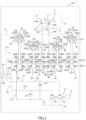
Figures 2 and3 are schematic illustrations of two embodiments a work machine realized according to the present invention. - With reference to
Figure 2 , number 1 denotes, as a whole, a work machine, in particular an earth-moving machine such as an excavator, a digger, a mechanical shovel or the like. - Work machine 1 comprises a
body 2 movable on the ground via ground engaging wheels or tracks (not illustrated). - In particular,
body 2 preferably comprises: a lower frame or undercarriage (not illustrated), which carries the ground engaging wheels or tracks to allow motion ofbody 2 with respect to the ground; and an upper frame (not illustrated) or superstructure, which is carried in a rotatable manner by lower frame preferably about a rotation axis orthogonal to the advancing plane of work machine 1, i.e. orthogonal to the ground. - In addition, work machine preferably comprises an internal combustion engine 4, which is configured to provide torque to allow motion of the
work machine 2, for instance by driving a hydraulic pump, which in turn is fluidly connected to hydraulic motors that drive in rotation the ground engaging wheels or tracks. - In addition, work machine 1 comprises a hydraulically actuated
work implement 6, which is carried bybody 2 and is configured to perform multiple earth moving operations, such as digging, handling earth or gravel, loading trucks and/or similar operations. In particular,work implement 6 is rotatably carried by the upper frame of work machine 1. - As known, the hydraulically actuated work implement 6 preferably comprises: a boom rotatably carried by the
body 2; a stick or arm or dipper rotatably carried by the boom; and a bucket and/or other similar tools rotatably carried by the arm. - In addition, work machine 1 preferably comprises one or more
hydraulic actuators 7, which are configured to operate the hydraulically actuatedwork implement 6. - In particular, the one or more
hydraulic actuators 7 may be configured to rotate the boom, the arm and/or the bucket with respect their corresponding hinge points. - More in detail, such a
hydraulic actuator 7 preferably comprises a double-acting hydraulic cylinder, in particular a two-chamber double-acting hydraulic cylinder. - With reference to the exemplary embodiment illustrated in
Figure 2 , in particular,hydraulic actuator 7 preferably comprises ahousing 8 which accommodates in a sliding and fluid tight manner apiston 9. Thepiston 9 defines within thehousing 8 twoopposite chamber piston 9. - As known, the hydraulic force Fhyd acting on
piston 9 can be calculated according to the following formula:
chamber 10a andchamber 10b respectively and A10a and A10b is the area ofchamber 10a andchamber 10b respectively. - In addition,
housing 8 is preferably provided with two openings/ports respective chamber - In addition,
hydraulic actuator 7 is preferably carried by work implement 6. - In other words, the one or more
hydraulic actuators 7 are preferably carried by the boom and/or the arm of work implement 6. - More in detail, the
housing 8 of the one or morehydraulic actuators 7 is fixedly carried by work implement 6, in particular by the boom and/or the arm of work implement 6. - With reference to a possible embodiment,
hydraulic actuators 7 preferably comprise one or more boom actuators, which are carried by thebody 2, are operatively interposed between thebody 2 and the boom and are configured to rotate the boom with respect to thebody 2. Preferably,hydraulic actuators 7 comprise two boom actuators arranged on opposite sides of the boom. - Preferably,
hydraulic actuators 7 further comprises at least one arm actuator (not illustrated), which is carried by the arm and is configured to rotate the arm with respect to the boom. - In addition,
hydraulic actuators 7 preferably comprise also at least one bucket actuator (not illustrated), which is preferably carried by the arm and is configured to rotate the bucket with respect to the arm. - With reference to the preferred embodiment illustrated in
Figure 2 , work machine 1 further comprise ahydraulic arrangement 14, which is fluidly connected tohydraulic actuator 7 and is configured to actuate this latter, in order to operate said work implement accordingly. - In particular,
hydraulic arrangement 14 is carried bybody 2 and is adapted to be fluidly connected tohydraulic actuator 7 by means ofhydraulic lines 15, in particular by means of flexiblehydraulic hoses 15. - With reference to the exemplary embodiment illustrated in
Figure 2 ,hydraulic lines 15 preferably comprises a line or hose 15a configured to be fluidly connected to opening 11a ofhydraulic actuator 7 and a line orhose 15b configured to be fluidly connected to opening 11b ofhydraulic actuator 7. - In addition,
hydraulic arrangement 14 preferably comprises a source of pressurizedhydraulic fluid 17, which is configured to provide at outlet a flow of pressurized hydraulic fluid. - More in detail, the source of pressurized hydraulic fluid preferably comprises pumping means 17, which are carried by internal combustion engine 4 and are configured to suck hydraulic fluid from a
tank 18 and to provide at outlet a pressurized flow of such hydraulic fluid. - In particular, the source of pressurized hydraulic fluid preferably comprises at least one hydraulic pump, which is preferably configured to be driven in rotation by internal combustion engine 4.
- More in detail, with reference to the example illustrated in
Figure 2 , the source of pressurized hydraulic fluid may comprise twohydraulic pumps hydraulic pumps - With reference to the exemplary embodiment illustrated in
Figure 2 ,hydraulic arrangement 14 further comprises ahydraulic circuit 20 which is adapted to put the outlet of the source of pressurized fluid, i.e. ofhydraulic pump 17 in fluid communication with thehydraulic actuator 7. - More in detail, the
hydraulic circuit 20 is preferably provided with a common pressure rails (CPR) configuration, i.e. it comprises a plurality of separate hydraulic lines/ pipes/rails/conduits 21, which are arranged in parallel to each other and are each configured to be fluidly connected between the source of pressurized fluid andhydraulic actuator 7. - That is, all the
hydraulic lines 21 of hydraulic circuit are selectively connectable tohydraulic actuator 7, in particular to bothchambers hydraulic actuator 7. - In particular, according to the CPR configuration,
hydraulic lines 21 ofhydraulic circuit 20 are preferably configured to operate with a pressure setting which is advantageously constant and is different to each other, in order each to be able to provide pressurized hydraulic fluid tohydraulic actuator 7 with different pressure levels. - More in detail,
hydraulic circuit 20 comprises at least twolines 21, which are arranged in parallel to each other and are adapted to fluidly connect the source of pressurized fluid withhydraulic actuator 7. - Preferably, the first one between the two
lines 21 is connected to the source of pressurized hydraulic fluid, while the second is preferably connected totank 18. - Accordingly, in operation, the first one between
lines 21 will define a high-pressure line and the other one betweenlines 21 will define a low-pressure line. - In particular, with reference to the example illustrated in
Figure 2 , hydraulic circuit comprises at least threelines -
Line 21a is preferably connected to the outlet ofhydraulic pump 17a,line 21b is preferably connected to the outlet ofhydraulic pump 17b andline 21c is preferably connected totank 18. - In addition,
hydraulic circuit 20 preferably comprises at least onehydraulic accumulator 22, which is fluidly connected to the first one between the twolines 21. - More in detail, with reference to the exemplary embodiment illustrated in
Figure 2 ,hydraulic circuit 20 preferably comprises twohydraulic accumulators lines - In use, by controlling the operation of
pumps lines accumulators lines accumulator Line 21c, being connected to tank, may define a low-pressure line. - With reference to the exemplary embodiment illustrated in
Figure 2 ,hydraulic circuit 20 preferably comprises at least onepressure relief valves 24, that are arranged downstream the source of pressurized hydraulic fluid along the first one betweenlines 21 and is configured to open when the pressure within the same line exceed a predetermined threshold. - More in detail,
hydraulic circuit 20 may comprise twopressure relief valves 24, which are operatively connected tolines - With reference to the exemplary embodiment illustrated in
Figure 2 ,hydraulic arrangement 14 further comprises acontrol valve arrangement 26, which is fluidly interposed betweenhydraulic circuit 20 andhydraulic actuator 7 and is configured to regulate the pressurized hydraulic fluid fed toward the samehydraulic actuator 7. - More in detail,
control valve arrangement 26 configured to selectively put at least the high-pressure line 21a and/or thelow pressure line 21c in fluid communication withchamber 10a and/orchamber 10b ofhydraulic actuator 7. - In other words, in operation
control valve arrangement 26 is configured to allow to selectively fluidly connect thechambers hydraulic actuator 7 withlines 21 ofhydraulic circuit 20. - In addition,
control valve arrangement 26 is preferably carried bybody 2.Control valve arrangement 26 is preferably configured to be fluidly connected tohydraulic actuator 7 viahydraulic lines 15. - More in detail, with reference to the exemplary embodiment illustrated in
Figure 2 ,control valve arrangement 26 comprises at least a first valve set 27, which is operatively interposed between thehydraulic circuit 20 and thefirst chamber 10a ofhydraulic actuator 7. - In addition,
control valve arrangement 26 comprises a second valve set 28, which is operatively interposed between thehydraulic circuit 20 and thesecond chamber 10b ofhydraulic actuator 7. - Valve sets 27 and 28 are preferably configured to be fluidly connected to the
respective chambers hydraulic actuator 7 respectively via hydraulic line 15a andhydraulic line 15b. - Preferably, each first valve set 27 and second valve set 28 comprises as many valves as
many lines 21 there are provided withinhydraulic circuit 20. Each valve of the first valve set 27 and of second valve set 28 is configured to be fluidly interposed between aline 21 ofhydraulic circuit 20 and therespective chamber hydraulic actuator 7, and is configured to selectively fluidly connect thecorresponding line 21 ofhydraulic circuit 20 with therespective chamber hydraulic actuator 7. - Preferably, valves or first valve set 27 and second valve set 28 are solenoid-controlled two-way two-position valves, in particular solenoid-controlled two-way two-position on-off valves, which are operable independently to each other and are operable between an open position and a closed position.
- With reference to the exemplary embodiment illustrated in
Figure 2 , in particular, valve sets 27 and 28 preferably each comprise threevalves 27a-27c and 28a-28c, which are fluidly interposed respectively between high-pressure line 21a, medium-pressure line 21b and low-pressure line 21c and therespective chamber hydraulic actuator 7. - According to the above, each
chamber hydraulic actuator 7, in operation, may assume at least three different pressure levels depending on the operation of valve sets 27 and 28. - With reference to the exemplary embodiment illustrated in
Figure 2 , in addition,hydraulic arrangement 14 preferably comprises one or more pressure multiplier or pressure amplifier or pressure boosterhydraulic cylinders 30, which are operatively interposed betweencontrol valve arrangement 26 andhydraulic actuator 7 and are configured to selectively increase the pressure of the hydraulic fluid provided towardshydraulic actuator 7. - Preferably, the one or more pressure multiplier
hydraulic cylinders 30 are carried bybody 2. - In addition, the one or more pressure multiplier
hydraulic cylinders 30 are each preferably adapted to be fluidly connected tohydraulic actuator 7 viahydraulic lines 15. - With reference to the exemplary embodiment illustrated in
Figure 2 , the one or more pressure multiplierhydraulic cylinders 30 preferably comprises single acting cylinders. - More in detail, the one or more pressure multiplier
hydraulic cylinders 30 comprises ahousing 31, which accommodates in a fluid tight and sliding manner apiston 32. Thepiston 32 defines a first chamber and a second chamber opposite to each other within the housing. Preferably, the first chamber has an area which is larger than the area of the second chamber, in particular the area of the first chamber may be twice the area of the second chamber. - Preferably, the first chamber, i.e. the larger chamber, of pressure multiplier hydraulic cylinder is fluidly connected to
hydraulic circuit 20 and the second chamber, i.e. the smaller chamber is fluidly connected tohydraulic actuator 7, in order to be able to increase the pressure of the hydraulic fluid fed towardshydraulic actuator 7. - Accordingly, the pressure of the fluid fed towards the
chambers hydraulic cylinder 30 is equal to the pressure of the fluid received by pressure multiplierhydraulic cylinder 30 from one of thelines 21, multiplied by the pressure multiplication factor, i.e. by the area ratio, of the same pressure multiplierhydraulic cylinder 30. - In other words, the pressure of the hydraulic fluid fed towards the
chamber hydraulic actuator 7 can be calculated according to the following formula:
chamber 10a orchamber 10b ofhydraulic actuator 7, p10 is the pressure of the hydraulic fluid fed bylines 21 towards pressure multiplierhydraulic cylinder 30 and α30 is the ratio between the areas of the two chamber of pressure multiplierhydraulic cylinder 30. - In addition,
valve arrangement 26 preferably comprises at least one further valve set, which is operatively interposed betweenhydraulic circuit 20 and pressure multiplierhydraulic cylinder 30, and is configured to selectively fluidly connect thelines 21 ofhydraulic circuit 20 with pressure multiplierhydraulic cylinder 30, in particular with the first chamber of pressure multiplierhydraulic cylinder 30. - Preferably, also the further valve set comprises as many valves as
many lines 21 there are provided withinhydraulic circuit 20. Each valve of the further valve set is configured to be fluidly interposed between aline 21 ofhydraulic circuit 20 and the first chamber of pressure multiplierhydraulic actuator 30, and is configured to selectively fluidly connect thecorresponding line 21 ofhydraulic circuit 20 with the first chamber of pressure multiplierhydraulic actuator 30. - Preferably, also the valves or the further valve set are solenoid-controlled two-way two-position valves, in particular solenoid-controlled two-way two-position on-off valves, which are operable independently to each other and are operable between an open position and a closed position.
- With reference to the exemplary embodiment illustrated in
Figure 2 , in particular, the further valve set preferably comprises three valves, which are fluidly interposed respectively between high-pressure line 21a, medium-pressure line 21b and low-pressure line 21c and the first chamber of pressure multiplier hydraulic cylinder. - In addition,
hydraulic arrangement 14 preferably comprises at least two pressure multiplierhydraulic cylinders 30, which are configured to be fluidly connected to arespective chamber hydraulic actuator 7 vialines 15a and 15b respectively. - Accordingly,
control valve arrangement 26 preferably comprises two further valve sets, each operatively couplet to a respective pressure multiplierhydraulic cylinder 30. - In more detail, with reference to the example illustrated in
Figure 2 ,hydraulic arrangement 14 may comprise four pressure multiplierhydraulic cylinders - Preferably, pressure multiplier
hydraulic cylinders chamber 10a ofhydraulic actuator 7, and pressure multiplierhydraulic cylinders chamber 10b ofhydraulic actuator 7. - Preferentially, the dimensions of pressure multiplier
hydraulic cylinders hydraulic cylinders - In addition, with reference to the exemplary embodiment illustrated in
Figure 2 ,control valve arrangement 26 preferably comprises four further valve sets 38, 39, 40, and 41, which are operatively interposed respectively betweenhydraulic circuit 20 and pressure multiplierhydraulic cylinders - In particular, valve sets 38, 39, 40, and 41 each comprise three
valves 38a-c, 39a-c, 40a-c, and 41a-c, which are fluidly interposed respectively between high-pressure line 21a, medium-pressure line 21b and low-pressure line 21c and the respective chamber pressure multiplierhydraulic cylinders - According to the above, each pressure multiplier
hydraulic cylinders - Preferably, valves of valve sets 38-41 are solenoid-controlled two-way two-position valves, in particular solenoid-controlled two-way two-position on-off valves, which are operable independently to each other and are operable between an open position and a closed position.
- The operation of the above-described
hydraulic arrangement 14 is the following. - During operation, the three
lines hydraulic circuit 20 are set at a different pressure level, to define a high-pressure line 21a, a medium-pressure line 21b and a low-pressure line 21c. - By operating the valves of
control valve arrangement 26, it is possible to selectively connect each of theline 21 with the twochambers hydraulic cylinders 30 through valve sets 38-41 or bypassing such pressure multiplierhydraulic cylinders 30 and feeding directly the hydraulic fluid fromlines 21 to thechambers hydraulic actuator 7 via valve sets 27 and 28. - In view of the foregoing, the advantages of a
hydraulic arrangement 14 according to the present invention are considerable and apparent. - In particular, the provision of pressure multiplier
hydraulic cylinders 30 carried by thebody 2 of work machine 1 allows to increase the number of discrete levels of hydraulic force Fhyd thehydraulic cylinder 7 is able to provide without however the need to employ asymmetrical multi-chamber hydraulic cylinders and to provide heavy and bulky valve arrangement on the work implement 6 of the work machine 1, with the evident advantages that this entails. - In particular, with reference to the exemplary embodiment illustrated in
Figure 2 , by providing three different constant pressure rails 21 and four differentpressure multiplier cylinders 30, it is possible to greatly increase the number of different discrete force level atactuator 7 available. - More in detail, the number of discrete values of the hydraulic force Fhyd acting on the
hydraulic actuator 7 piston can still be calculated according to following formula
hydraulic actuator 7 plus the number of chambers of pressure multiplier hydraulic cylinders. - In the example illustrated in
Figure 2 , there are provided 6 different chambers, i.e. two of thehydraulic actuator 7 and four of the four pressure multiplierhydraulic cylinders 30. - Therefore, the number of discrete values of the hydraulic force Fhyd acting on the
hydraulic actuator 7 piston will be equal to 36, i.e. 729. - In addition, the proposed layout allows to continue arranging the traditional double-effect hydraulic cylinders on the work implement 6 of the work machine 1, which are much cheaper, reliable and simpler than asymmetrical multi-chamber hydraulic cylinders and at the same time does not impact on the inertia and weight of the work implement 6 of work machine 1, i.e. it does not affect the lifting capacity of work machine 1.
- Furthermore, by simply increasing the number of
pressure multiplier cylinders 30 and/or lines or common pressure rails 21 it is possible to easily increase the number of discrete levels of hydraulic force Fhyd thehydraulic cylinder 7 is able to provide, i.e. to increase the resolution of the hydraulic force Fhyd thehydraulic cylinder 7 is able to provide. On the contrary, in thehydraulic circuit 100 according to the prior art, the use of asymmetrical multi-chamber hydraulic cylinders does not allow to easily increase the number of discrete hydraulic force levels. - Lastly, by providing pressure multiplier
hydraulic cylinder 30, it is possible to increase the pressure at thehydraulic actuator 7 and therefore the hydraulic force thehydraulic actuator 7 is able to exert without increasing the fluid pressure within the high-pressure rail 21a. - It is clear that modifications can be made to the described hydraulic arrangement 4, which do not extend beyond the scope of protection defined by the claims.
- In particular, the number of pressure multipliers hydraulic cylinders and/or the configuration of
control valve arrangement 26 may be different, on the basis of the number of discrete levels of the hydraulic force Fhyd to be obtained. - In addition, the layout of the source of pressurized fluid,
pressure relief valves 24 and/or hydraulic accumulators may be different. - Lastly,
Figure 3 illustrates ahydraulic arrangement 214, which is similar tohydraulic arrangement 14 and whose corresponding parts will be denoted with the same reference numbers ashydraulic arrangement 14. -
Hydraulic arrangement 214 distinguishes fromhydraulic arrangement 14 in thatpressure multiplier cylinder 30 are double acting hydraulic cylinders. - More in detail, according to the embodiment illustrated in
Figure 2 ,pressure multiplier cylinder 30 may comprise ahousing 231, which accommodates in a fluid tight and sliding manner apiston assembly 232. Thepiston assembly 32 defines four chambers withinhousing 231, twoside chambers 233a between the two axial end ofhousing 231 and facing portion of the piston assembly and twocentral chambers 233b between portion of thesame piston assembly 232. - More in detail, the
piston assembly 232 is preferably realized in one piece and comprises three pistons, which are rigidly fixed to each other and delimit the four chambers. -
Side chambers 233a are preferably smaller thancentral chambers 233b and are fluidly connected tohydraulic actuator 7. -
Central chambers 233b, on the other hand, are preferably fluidly connected tohydraulic circuit 20 via a respective valve set ofcontrol valve arrangement 26. - In even more detail,
control valve arrangement 26 preferably comprise as many pairs of valves asmany lines 21 there are provided inhydraulic circuit 20, wherein each pair of valves is operatively interposed between the correspondingcentral chambers 233b and acorresponding line 21. - In particular, according to the illustrated example in
Figure 3 , valve sets 38, 39, 40, and 41 each comprise threevalve pairs 238a'-c", 239a'-c", 240a'-c", and 241a'-c", which are fluidly interposed respectively between high-pressure line 21a, medium-pressure line 21b and low-pressure line 21c and the respectivecentral chambers 233b of pressure multiplierhydraulic cylinders - In addition, valve sets 38, 39, 40, and 41 are preferably provided with check valves in fluid communication with
side chambers 233a, which are configured to allow unidirectional flow of the hydraulic fluid fromhydraulic circuit 20 withinside chambers 233a and towardshydraulic actuator 7. - The technical effect associated with the provision of double effect pressure multiplier hydraulic cylinder is related to the possibility of providing a continuous flowrate of pressurized hydraulic fluid towards the hydraulic actuator even when the
piston 232 reaches an end of its stroke, as it is possible to invert thepiston 232 stroke withinhousing 231 by commuting the respective valve set 38, 39, 40 or 41.
Claims (13)
- A hydraulic arrangement (14) for a work machine (1); said work machine (1) comprising: a body (2) movable on the ground by means of ground engaging means; and a hydraulically actuated work implement (6), which is rotatably carried by said body (2) and is configured to perform multiple earth moving operations;said hydraulic arrangement (14) comprising:• a source of pressurized hydraulic fluid (17), which is configured to suck hydraulic fluid from a tank (18) and to provide at outlet a pressurized flow of the hydraulic fluid;• at least one hydraulic actuator (7), which is configured to operate said hydraulically actuated work implement (6); and• a hydraulic circuit (20), which is configured to be arranged on said body (2) and is configured to put the outlet of said source of hydraulic fluid (17) in fluid communication with said hydraulic actuator (7);said hydraulic actuator (7) comprising: a housing (8), and a piston (9), which is accommodated in a fluid-tight and sliding manner within said housing (8) and defines within said housing (8) a first chamber (10a) and a second chamber (10b), opposite to said first chamber (10a);said hydraulic circuit (20) comprising:• a first hydraulic line (21a), which fluidly connects said source of pressurized hydraulic fluid (17) with said hydraulic actuator (7);• a first hydraulic accumulator (22a) fluidly connected to said first hydraulic line (21a);• a second hydraulic line (21c), which is arranged in parallel to said first hydraulic line (21a) and fluidly connects said tank (18) with said hydraulic actuator (7);said hydraulic arrangement (14) further comprising:• a control valve arrangement (26), which is operatively interposed between said hydraulic circuit (20) and said hydraulic actuator (7) and is configured to selectively put said first hydraulic line (21a) and/or said second hydraulic line (21c) in fluid communication with said first chamber (10a) and/or said second chamber (10b); and• at least one pressure multiplier hydraulic cylinder (30), which is operatively interposed between said control valve arrangement (26) and said hydraulic actuator (7) and is configured to increase the pressure of the hydraulic fluid provided by said hydraulic circuit (20) to be fed towards said hydraulic actuator (7).
- Hydraulic arrangement (14) according to claim 1, wherein said control valve arrangement (26) comprises:a first valve set (27) operatively interposed between said hydraulic circuit (20) and the first chamber (10a) of said hydraulic actuator (7); anda second valve set (28) operatively interposed between said hydraulic circuit (20) and the second chamber (10b) of said hydraulic actuator (7).
- Hydraulic arrangement according to claim 2, wherein said control valve arrangement (26) further comprises a third valve set (38, 39, 40, 41), which is operatively interposed between said hydraulic circuit (20) and said pressure multiplier hydraulic cylinder (30).
- Hydraulic arrangement according to claim 3, wherein each said first valve set (27), said second valve set (28) and said third valve set (38, 39, 40, 41) comprises a plurality of control valves, each configured to be fluidly interposed between a corresponding line (21a, 21b, 21c) of said hydraulic circuit (20) and said hydraulic actuators (7).
- Hydraulic arrangement according to claim 4, wherein said control valves are solenoid controlled two-way two-position valves, in particular two-way two-position logic valves.
- Hydraulic arrangement according to claim 4 or 5, wherein each said first valve set (27), said second valve set (28) and said third valve set (38, 39, 40, 41) comprises comprises as many control valves as many separate lines (21) there are provided within said hydraulic circuit (20).
- Hydraulic arrangement according to any of the preceding claims, comprising at least a first pressure multiplier hydraulic cylinder (30) fluidly connected to the first chamber (10a) of said hydraulic actuator (7) and at least a second pressure multiplier hydraulic cylinder (30) fluidly connected to the second chamber (10b) of said hydraulic actuator (7).
- Hydraulic arrangement according to any of the preceding claims, wherein said pressure multiplier hydraulic cylinder (30) comprises a second housing (31) and a second piston (32) which is accommodated in a sliding and fluid tight manner within said second housing (31) and defines a third chamber (33a) and a fourth chamber (33b) opposite to said third chamber (33a);said third chamber (33a) being fluidly connected to said hydraulic circuit (20) and said fourth chamber (33b) being fluidly connected to said hydraulic actuator (7);said third chamber (33a) having an area larger than the area of said fourth chamber (33b).
- Hydraulic arrangement according to any of the preceding claims, wherein said hydraulic circuit (20) further comprises:• a third hydraulic line (21b), which fluidly connects said source of pressurized hydraulic fluid (17) with said hydraulic actuator (7) and is arranged in parallel to said first hydraulic line (21a); and• a second hydraulic accumulator (22b) fluidly connected to said second hydraulic line (21b).
- A work machine (1) comprising: a body (2) movable on the ground by means of ground engaging means; a hydraulically actuated work implement (6), which is rotatably carried by said body (2) and is configured to perform multiple earth moving operations; and an hydraulic arrangement (14), which is realized according to any of the preceding claims.
- Work machine realized according to claim 10, wherein said hydraulically actuated work implement (6) comprises: a boom rotatably carried by said body (2); an arm rotatably carried by said boom; and a bucket or other similar tool rotatably carried by said arm;
said hydraulic actuator (7) being carried by said hydraulic actuated work implement (6) and being configured to rotate said boom with respect to said body (2) and/or said arm with respect to said boom, and/or said bucket or other similar tool with respect to said arm. - Work machine according to claim 10 or 11, wherein said hydraulic circuit (20) is arranged on said body (2).
- Work machine according to claim 12, wherein said hydraulic arrangement (14) comprises two lines (15a, 15b), in particular two flexible hoses (15a, 15b) fluidly connecting said hydraulic circuit with said hydraulic actuator (7), in particular respectively with the first (10a) and the second chamber (10b) of said hydraulic actuator (7).
Applications Claiming Priority (1)
| Application Number | Priority Date | Filing Date | Title |
|---|---|---|---|
| IT102023000014595A IT202300014595A1 (en) | 2023-07-12 | 2023-07-12 | IMPROVED HYDRAULIC SYSTEM FOR A WORK MACHINE AND WORK MACHINERY INCLUDING SUCH HYDRAULIC SYSTEM |
Publications (1)
| Publication Number | Publication Date |
|---|---|
| EP4491810A1 true EP4491810A1 (en) | 2025-01-15 |
Family
ID=88098065
Family Applications (1)
| Application Number | Title | Priority Date | Filing Date |
|---|---|---|---|
| EP24188431.1A Pending EP4491810A1 (en) | 2023-07-12 | 2024-07-12 | Improved hydraulic arrangement for a work machine and work machine comprising such hydraulic arrangement |
Country Status (2)
| Country | Link |
|---|---|
| EP (1) | EP4491810A1 (en) |
| IT (1) | IT202300014595A1 (en) |
Citations (1)
| Publication number | Priority date | Publication date | Assignee | Title |
|---|---|---|---|---|
| US20180180065A1 (en) * | 2016-12-22 | 2018-06-28 | Eagle Industry Co., Ltd. | Fluid circuit |
-
2023
- 2023-07-12 IT IT102023000014595A patent/IT202300014595A1/en unknown
-
2024
- 2024-07-12 EP EP24188431.1A patent/EP4491810A1/en active Pending
Patent Citations (1)
| Publication number | Priority date | Publication date | Assignee | Title |
|---|---|---|---|---|
| US20180180065A1 (en) * | 2016-12-22 | 2018-06-28 | Eagle Industry Co., Ltd. | Fluid circuit |
Also Published As
| Publication number | Publication date |
|---|---|
| IT202300014595A1 (en) | 2025-01-12 |
Similar Documents
| Publication | Publication Date | Title |
|---|---|---|
| US7500360B2 (en) | Hydraulic driving system of construction machinery | |
| JP6328548B2 (en) | Work machine | |
| CN203892301U (en) | Meterless hydraulic system having multi-circuit recuperation | |
| CN101278131B (en) | Multi-pump control system and method | |
| US8984873B2 (en) | Meterless hydraulic system having flow sharing and combining functionality | |
| US9932993B2 (en) | System and method for hydraulic energy recovery | |
| CN104520594B (en) | Meterless hydraulics with force modulation | |
| US20130081382A1 (en) | Regeneration configuration for closed-loop hydraulic systems | |
| US8966891B2 (en) | Meterless hydraulic system having pump protection | |
| US20130098019A1 (en) | Meterless Hydraulic System Having Flow Sharing and Combining Functionality | |
| JP5060734B2 (en) | Hydraulic system with variable back pressure control | |
| KR100248186B1 (en) | Hydraulic control system | |
| WO2013003046A2 (en) | Hydraulic control system having swing motor energy recovery | |
| CN104114879A (en) | Closed-Loop Hydraulic System Having Flow Combining and Recuperation | |
| JP2015206420A (en) | Hydraulic drive unit for construction machinery | |
| JP5358148B2 (en) | Switching valve operating mechanism for work vehicles | |
| EP4491809A1 (en) | Improved hydraulic arrangement for a work machine, control method thereof, and work machine comprising such hydraulic arrangement | |
| US20140033697A1 (en) | Meterless hydraulic system having force modulation | |
| US20140033698A1 (en) | Meterless hydraulic system having force modulation | |
| CN104583610B (en) | Hydraulic control system having swing motor energy recovery | |
| KR20210136084A (en) | hydraulic machine | |
| US5701796A (en) | Hydraulic apparatus for traveling | |
| EP4495338A1 (en) | Improved work machine | |
| EP4575104A1 (en) | Improved work machine | |
| JP4423149B2 (en) | Construction machinery |
Legal Events
| Date | Code | Title | Description |
|---|---|---|---|
| PUAI | Public reference made under article 153(3) epc to a published international application that has entered the european phase |
Free format text: ORIGINAL CODE: 0009012 |
|
| STAA | Information on the status of an ep patent application or granted ep patent |
Free format text: STATUS: THE APPLICATION HAS BEEN PUBLISHED |
|
| AK | Designated contracting states |
Kind code of ref document: A1 Designated state(s): AL AT BE BG CH CY CZ DE DK EE ES FI FR GB GR HR HU IE IS IT LI LT LU LV MC ME MK MT NL NO PL PT RO RS SE SI SK SM TR |
|
| STAA | Information on the status of an ep patent application or granted ep patent |
Free format text: STATUS: REQUEST FOR EXAMINATION WAS MADE |
|
| 17P | Request for examination filed |
Effective date: 20250715 |
|
| GRAP | Despatch of communication of intention to grant a patent |
Free format text: ORIGINAL CODE: EPIDOSNIGR1 |
|
| STAA | Information on the status of an ep patent application or granted ep patent |
Free format text: STATUS: GRANT OF PATENT IS INTENDED |
|
| RIC1 | Information provided on ipc code assigned before grant |
Ipc: E02F 9/22 20060101AFI20260709BHEP Ipc: F15B 11/17 20060101ALI20260709BHEP |