EP4491809A1 - Improved hydraulic arrangement for a work machine, control method thereof, and work machine comprising such hydraulic arrangement - Google Patents
Improved hydraulic arrangement for a work machine, control method thereof, and work machine comprising such hydraulic arrangement Download PDFInfo
- Publication number
- EP4491809A1 EP4491809A1 EP24188145.7A EP24188145A EP4491809A1 EP 4491809 A1 EP4491809 A1 EP 4491809A1 EP 24188145 A EP24188145 A EP 24188145A EP 4491809 A1 EP4491809 A1 EP 4491809A1
- Authority
- EP
- European Patent Office
- Prior art keywords
- hydraulic
- line
- chamber
- fluid
- accumulator
- Prior art date
- Legal status (The legal status is an assumption and is not a legal conclusion. Google has not performed a legal analysis and makes no representation as to the accuracy of the status listed.)
- Pending
Links
Images


Classifications
-
- E—FIXED CONSTRUCTIONS
- E02—HYDRAULIC ENGINEERING; FOUNDATIONS; SOIL SHIFTING
- E02F—DREDGING; SOIL-SHIFTING
- E02F9/00—Component parts of dredgers or soil-shifting machines, not restricted to one of the kinds covered by groups E02F3/00 - E02F7/00
- E02F9/20—Drives; Control devices
- E02F9/22—Hydraulic or pneumatic drives
- E02F9/2221—Control of flow rate; Load sensing arrangements
- E02F9/2232—Control of flow rate; Load sensing arrangements using one or more variable displacement pumps
- E02F9/2235—Control of flow rate; Load sensing arrangements using one or more variable displacement pumps including an electronic controller
-
- E—FIXED CONSTRUCTIONS
- E02—HYDRAULIC ENGINEERING; FOUNDATIONS; SOIL SHIFTING
- E02F—DREDGING; SOIL-SHIFTING
- E02F9/00—Component parts of dredgers or soil-shifting machines, not restricted to one of the kinds covered by groups E02F3/00 - E02F7/00
- E02F9/20—Drives; Control devices
- E02F9/22—Hydraulic or pneumatic drives
- E02F9/2217—Hydraulic or pneumatic drives with energy recovery arrangements, e.g. using accumulators, flywheels
-
- E—FIXED CONSTRUCTIONS
- E02—HYDRAULIC ENGINEERING; FOUNDATIONS; SOIL SHIFTING
- E02F—DREDGING; SOIL-SHIFTING
- E02F9/00—Component parts of dredgers or soil-shifting machines, not restricted to one of the kinds covered by groups E02F3/00 - E02F7/00
- E02F9/20—Drives; Control devices
- E02F9/22—Hydraulic or pneumatic drives
- E02F9/2221—Control of flow rate; Load sensing arrangements
- E02F9/2225—Control of flow rate; Load sensing arrangements using pressure-compensating valves
- E02F9/2228—Control of flow rate; Load sensing arrangements using pressure-compensating valves including an electronic controller
-
- E—FIXED CONSTRUCTIONS
- E02—HYDRAULIC ENGINEERING; FOUNDATIONS; SOIL SHIFTING
- E02F—DREDGING; SOIL-SHIFTING
- E02F9/00—Component parts of dredgers or soil-shifting machines, not restricted to one of the kinds covered by groups E02F3/00 - E02F7/00
- E02F9/20—Drives; Control devices
- E02F9/22—Hydraulic or pneumatic drives
- E02F9/2278—Hydraulic circuits
- E02F9/2292—Systems with two or more pumps
-
- F—MECHANICAL ENGINEERING; LIGHTING; HEATING; WEAPONS; BLASTING
- F15—FLUID-PRESSURE ACTUATORS; HYDRAULICS OR PNEUMATICS IN GENERAL
- F15B—SYSTEMS ACTING BY MEANS OF FLUIDS IN GENERAL; FLUID-PRESSURE ACTUATORS, e.g. SERVOMOTORS; DETAILS OF FLUID-PRESSURE SYSTEMS, NOT OTHERWISE PROVIDED FOR
- F15B1/00—Installations or systems with accumulators; Supply reservoir or sump assemblies
- F15B1/02—Installations or systems with accumulators
-
- F—MECHANICAL ENGINEERING; LIGHTING; HEATING; WEAPONS; BLASTING
- F15—FLUID-PRESSURE ACTUATORS; HYDRAULICS OR PNEUMATICS IN GENERAL
- F15B—SYSTEMS ACTING BY MEANS OF FLUIDS IN GENERAL; FLUID-PRESSURE ACTUATORS, e.g. SERVOMOTORS; DETAILS OF FLUID-PRESSURE SYSTEMS, NOT OTHERWISE PROVIDED FOR
- F15B1/00—Installations or systems with accumulators; Supply reservoir or sump assemblies
- F15B1/02—Installations or systems with accumulators
- F15B1/024—Installations or systems with accumulators used as a supplementary power source, e.g. to store energy in idle periods to balance pump load
-
- F—MECHANICAL ENGINEERING; LIGHTING; HEATING; WEAPONS; BLASTING
- F15—FLUID-PRESSURE ACTUATORS; HYDRAULICS OR PNEUMATICS IN GENERAL
- F15B—SYSTEMS ACTING BY MEANS OF FLUIDS IN GENERAL; FLUID-PRESSURE ACTUATORS, e.g. SERVOMOTORS; DETAILS OF FLUID-PRESSURE SYSTEMS, NOT OTHERWISE PROVIDED FOR
- F15B1/00—Installations or systems with accumulators; Supply reservoir or sump assemblies
- F15B1/02—Installations or systems with accumulators
- F15B1/027—Installations or systems with accumulators having accumulator charging devices
- F15B1/033—Installations or systems with accumulators having accumulator charging devices with electrical control means
-
- F—MECHANICAL ENGINEERING; LIGHTING; HEATING; WEAPONS; BLASTING
- F15—FLUID-PRESSURE ACTUATORS; HYDRAULICS OR PNEUMATICS IN GENERAL
- F15B—SYSTEMS ACTING BY MEANS OF FLUIDS IN GENERAL; FLUID-PRESSURE ACTUATORS, e.g. SERVOMOTORS; DETAILS OF FLUID-PRESSURE SYSTEMS, NOT OTHERWISE PROVIDED FOR
- F15B11/00—Servomotor systems without provision for follow-up action ; Circuits therefor
- F15B11/02—Systems essentially incorporating special features for controlling the speed or the actuating force of an output member
- F15B11/04—Systems essentially incorporating special features for controlling the speed or the actuating force of an output member for controlling the speed
- F15B11/042—Systems essentially incorporating special features for controlling the speed or the actuating force of an output member for controlling the speed by means in the feed line
- F15B11/0426—Systems essentially incorporating special features for controlling the speed or the actuating force of an output member for controlling the speed by means in the feed line by controlling the number of pumps or parallel valves switched on
-
- F—MECHANICAL ENGINEERING; LIGHTING; HEATING; WEAPONS; BLASTING
- F15—FLUID-PRESSURE ACTUATORS; HYDRAULICS OR PNEUMATICS IN GENERAL
- F15B—SYSTEMS ACTING BY MEANS OF FLUIDS IN GENERAL; FLUID-PRESSURE ACTUATORS, e.g. SERVOMOTORS; DETAILS OF FLUID-PRESSURE SYSTEMS, NOT OTHERWISE PROVIDED FOR
- F15B11/00—Servomotor systems without provision for follow-up action ; Circuits therefor
- F15B11/16—Servomotor systems without provision for follow-up action ; Circuits therefor with two or more servomotors
- F15B11/17—Servomotor systems without provision for follow-up action ; Circuits therefor with two or more servomotors using two or more pumps
-
- F—MECHANICAL ENGINEERING; LIGHTING; HEATING; WEAPONS; BLASTING
- F15—FLUID-PRESSURE ACTUATORS; HYDRAULICS OR PNEUMATICS IN GENERAL
- F15B—SYSTEMS ACTING BY MEANS OF FLUIDS IN GENERAL; FLUID-PRESSURE ACTUATORS, e.g. SERVOMOTORS; DETAILS OF FLUID-PRESSURE SYSTEMS, NOT OTHERWISE PROVIDED FOR
- F15B21/00—Common features of fluid actuator systems; Fluid-pressure actuator systems or details thereof, not covered by any other group of this subclass
- F15B21/14—Energy-recuperation means
-
- F—MECHANICAL ENGINEERING; LIGHTING; HEATING; WEAPONS; BLASTING
- F15—FLUID-PRESSURE ACTUATORS; HYDRAULICS OR PNEUMATICS IN GENERAL
- F15B—SYSTEMS ACTING BY MEANS OF FLUIDS IN GENERAL; FLUID-PRESSURE ACTUATORS, e.g. SERVOMOTORS; DETAILS OF FLUID-PRESSURE SYSTEMS, NOT OTHERWISE PROVIDED FOR
- F15B1/00—Installations or systems with accumulators; Supply reservoir or sump assemblies
- F15B1/02—Installations or systems with accumulators
- F15B1/04—Accumulators
- F15B1/08—Accumulators using a gas cushion; Gas charging devices; Indicators or floats therefor
- F15B1/24—Accumulators using a gas cushion; Gas charging devices; Indicators or floats therefor with rigid separating means, e.g. pistons
-
- F—MECHANICAL ENGINEERING; LIGHTING; HEATING; WEAPONS; BLASTING
- F15—FLUID-PRESSURE ACTUATORS; HYDRAULICS OR PNEUMATICS IN GENERAL
- F15B—SYSTEMS ACTING BY MEANS OF FLUIDS IN GENERAL; FLUID-PRESSURE ACTUATORS, e.g. SERVOMOTORS; DETAILS OF FLUID-PRESSURE SYSTEMS, NOT OTHERWISE PROVIDED FOR
- F15B2201/00—Accumulators
- F15B2201/20—Accumulator cushioning means
- F15B2201/205—Accumulator cushioning means using gas
-
- F—MECHANICAL ENGINEERING; LIGHTING; HEATING; WEAPONS; BLASTING
- F15—FLUID-PRESSURE ACTUATORS; HYDRAULICS OR PNEUMATICS IN GENERAL
- F15B—SYSTEMS ACTING BY MEANS OF FLUIDS IN GENERAL; FLUID-PRESSURE ACTUATORS, e.g. SERVOMOTORS; DETAILS OF FLUID-PRESSURE SYSTEMS, NOT OTHERWISE PROVIDED FOR
- F15B2201/00—Accumulators
- F15B2201/30—Accumulator separating means
- F15B2201/31—Accumulator separating means having rigid separating means, e.g. pistons
-
- F—MECHANICAL ENGINEERING; LIGHTING; HEATING; WEAPONS; BLASTING
- F15—FLUID-PRESSURE ACTUATORS; HYDRAULICS OR PNEUMATICS IN GENERAL
- F15B—SYSTEMS ACTING BY MEANS OF FLUIDS IN GENERAL; FLUID-PRESSURE ACTUATORS, e.g. SERVOMOTORS; DETAILS OF FLUID-PRESSURE SYSTEMS, NOT OTHERWISE PROVIDED FOR
- F15B2201/00—Accumulators
- F15B2201/30—Accumulator separating means
- F15B2201/32—Accumulator separating means having multiple separating means, e.g. with an auxiliary piston sliding within a main piston, multiple membranes or combinations thereof
-
- F—MECHANICAL ENGINEERING; LIGHTING; HEATING; WEAPONS; BLASTING
- F15—FLUID-PRESSURE ACTUATORS; HYDRAULICS OR PNEUMATICS IN GENERAL
- F15B—SYSTEMS ACTING BY MEANS OF FLUIDS IN GENERAL; FLUID-PRESSURE ACTUATORS, e.g. SERVOMOTORS; DETAILS OF FLUID-PRESSURE SYSTEMS, NOT OTHERWISE PROVIDED FOR
- F15B2211/00—Circuits for servomotor systems
- F15B2211/20—Fluid pressure source, e.g. accumulator or variable axial piston pump
- F15B2211/205—Systems with pumps
- F15B2211/2053—Type of pump
- F15B2211/20546—Type of pump variable capacity
-
- F—MECHANICAL ENGINEERING; LIGHTING; HEATING; WEAPONS; BLASTING
- F15—FLUID-PRESSURE ACTUATORS; HYDRAULICS OR PNEUMATICS IN GENERAL
- F15B—SYSTEMS ACTING BY MEANS OF FLUIDS IN GENERAL; FLUID-PRESSURE ACTUATORS, e.g. SERVOMOTORS; DETAILS OF FLUID-PRESSURE SYSTEMS, NOT OTHERWISE PROVIDED FOR
- F15B2211/00—Circuits for servomotor systems
- F15B2211/20—Fluid pressure source, e.g. accumulator or variable axial piston pump
- F15B2211/205—Systems with pumps
- F15B2211/20576—Systems with pumps with multiple pumps
-
- F—MECHANICAL ENGINEERING; LIGHTING; HEATING; WEAPONS; BLASTING
- F15—FLUID-PRESSURE ACTUATORS; HYDRAULICS OR PNEUMATICS IN GENERAL
- F15B—SYSTEMS ACTING BY MEANS OF FLUIDS IN GENERAL; FLUID-PRESSURE ACTUATORS, e.g. SERVOMOTORS; DETAILS OF FLUID-PRESSURE SYSTEMS, NOT OTHERWISE PROVIDED FOR
- F15B2211/00—Circuits for servomotor systems
- F15B2211/20—Fluid pressure source, e.g. accumulator or variable axial piston pump
- F15B2211/21—Systems with pressure sources other than pumps, e.g. with a pyrotechnical charge
- F15B2211/212—Systems with pressure sources other than pumps, e.g. with a pyrotechnical charge the pressure sources being accumulators
-
- F—MECHANICAL ENGINEERING; LIGHTING; HEATING; WEAPONS; BLASTING
- F15—FLUID-PRESSURE ACTUATORS; HYDRAULICS OR PNEUMATICS IN GENERAL
- F15B—SYSTEMS ACTING BY MEANS OF FLUIDS IN GENERAL; FLUID-PRESSURE ACTUATORS, e.g. SERVOMOTORS; DETAILS OF FLUID-PRESSURE SYSTEMS, NOT OTHERWISE PROVIDED FOR
- F15B2211/00—Circuits for servomotor systems
- F15B2211/30—Directional control
- F15B2211/305—Directional control characterised by the type of valves
- F15B2211/3056—Assemblies of multiple valves
- F15B2211/30565—Assemblies of multiple valves having multiple valves for a single output member, e.g. for creating higher valve function by use of multiple valves like two 2/2-valves replacing a 5/3-valve
-
- F—MECHANICAL ENGINEERING; LIGHTING; HEATING; WEAPONS; BLASTING
- F15—FLUID-PRESSURE ACTUATORS; HYDRAULICS OR PNEUMATICS IN GENERAL
- F15B—SYSTEMS ACTING BY MEANS OF FLUIDS IN GENERAL; FLUID-PRESSURE ACTUATORS, e.g. SERVOMOTORS; DETAILS OF FLUID-PRESSURE SYSTEMS, NOT OTHERWISE PROVIDED FOR
- F15B2211/00—Circuits for servomotor systems
- F15B2211/30—Directional control
- F15B2211/305—Directional control characterised by the type of valves
- F15B2211/3056—Assemblies of multiple valves
- F15B2211/30565—Assemblies of multiple valves having multiple valves for a single output member, e.g. for creating higher valve function by use of multiple valves like two 2/2-valves replacing a 5/3-valve
- F15B2211/30575—Assemblies of multiple valves having multiple valves for a single output member, e.g. for creating higher valve function by use of multiple valves like two 2/2-valves replacing a 5/3-valve in a Wheatstone Bridge arrangement (also half bridges)
-
- F—MECHANICAL ENGINEERING; LIGHTING; HEATING; WEAPONS; BLASTING
- F15—FLUID-PRESSURE ACTUATORS; HYDRAULICS OR PNEUMATICS IN GENERAL
- F15B—SYSTEMS ACTING BY MEANS OF FLUIDS IN GENERAL; FLUID-PRESSURE ACTUATORS, e.g. SERVOMOTORS; DETAILS OF FLUID-PRESSURE SYSTEMS, NOT OTHERWISE PROVIDED FOR
- F15B2211/00—Circuits for servomotor systems
- F15B2211/30—Directional control
- F15B2211/315—Directional control characterised by the connections of the valve or valves in the circuit
- F15B2211/31523—Directional control characterised by the connections of the valve or valves in the circuit being connected to a pressure source and an output member
- F15B2211/31535—Directional control characterised by the connections of the valve or valves in the circuit being connected to a pressure source and an output member having multiple pressure sources and a single output member
-
- F—MECHANICAL ENGINEERING; LIGHTING; HEATING; WEAPONS; BLASTING
- F15—FLUID-PRESSURE ACTUATORS; HYDRAULICS OR PNEUMATICS IN GENERAL
- F15B—SYSTEMS ACTING BY MEANS OF FLUIDS IN GENERAL; FLUID-PRESSURE ACTUATORS, e.g. SERVOMOTORS; DETAILS OF FLUID-PRESSURE SYSTEMS, NOT OTHERWISE PROVIDED FOR
- F15B2211/00—Circuits for servomotor systems
- F15B2211/30—Directional control
- F15B2211/32—Directional control characterised by the type of actuation
- F15B2211/327—Directional control characterised by the type of actuation electrically or electronically
-
- F—MECHANICAL ENGINEERING; LIGHTING; HEATING; WEAPONS; BLASTING
- F15—FLUID-PRESSURE ACTUATORS; HYDRAULICS OR PNEUMATICS IN GENERAL
- F15B—SYSTEMS ACTING BY MEANS OF FLUIDS IN GENERAL; FLUID-PRESSURE ACTUATORS, e.g. SERVOMOTORS; DETAILS OF FLUID-PRESSURE SYSTEMS, NOT OTHERWISE PROVIDED FOR
- F15B2211/00—Circuits for servomotor systems
- F15B2211/40—Flow control
- F15B2211/405—Flow control characterised by the type of flow control means or valve
- F15B2211/40576—Assemblies of multiple valves
- F15B2211/40592—Assemblies of multiple valves with multiple valves in parallel flow paths
-
- F—MECHANICAL ENGINEERING; LIGHTING; HEATING; WEAPONS; BLASTING
- F15—FLUID-PRESSURE ACTUATORS; HYDRAULICS OR PNEUMATICS IN GENERAL
- F15B—SYSTEMS ACTING BY MEANS OF FLUIDS IN GENERAL; FLUID-PRESSURE ACTUATORS, e.g. SERVOMOTORS; DETAILS OF FLUID-PRESSURE SYSTEMS, NOT OTHERWISE PROVIDED FOR
- F15B2211/00—Circuits for servomotor systems
- F15B2211/40—Flow control
- F15B2211/42—Flow control characterised by the type of actuation
- F15B2211/426—Flow control characterised by the type of actuation electrically or electronically
-
- F—MECHANICAL ENGINEERING; LIGHTING; HEATING; WEAPONS; BLASTING
- F15—FLUID-PRESSURE ACTUATORS; HYDRAULICS OR PNEUMATICS IN GENERAL
- F15B—SYSTEMS ACTING BY MEANS OF FLUIDS IN GENERAL; FLUID-PRESSURE ACTUATORS, e.g. SERVOMOTORS; DETAILS OF FLUID-PRESSURE SYSTEMS, NOT OTHERWISE PROVIDED FOR
- F15B2211/00—Circuits for servomotor systems
- F15B2211/60—Circuit components or control therefor
- F15B2211/625—Accumulators
-
- F—MECHANICAL ENGINEERING; LIGHTING; HEATING; WEAPONS; BLASTING
- F15—FLUID-PRESSURE ACTUATORS; HYDRAULICS OR PNEUMATICS IN GENERAL
- F15B—SYSTEMS ACTING BY MEANS OF FLUIDS IN GENERAL; FLUID-PRESSURE ACTUATORS, e.g. SERVOMOTORS; DETAILS OF FLUID-PRESSURE SYSTEMS, NOT OTHERWISE PROVIDED FOR
- F15B2211/00—Circuits for servomotor systems
- F15B2211/60—Circuit components or control therefor
- F15B2211/63—Electronic controllers
- F15B2211/6303—Electronic controllers using input signals
- F15B2211/6306—Electronic controllers using input signals representing a pressure
-
- F—MECHANICAL ENGINEERING; LIGHTING; HEATING; WEAPONS; BLASTING
- F15—FLUID-PRESSURE ACTUATORS; HYDRAULICS OR PNEUMATICS IN GENERAL
- F15B—SYSTEMS ACTING BY MEANS OF FLUIDS IN GENERAL; FLUID-PRESSURE ACTUATORS, e.g. SERVOMOTORS; DETAILS OF FLUID-PRESSURE SYSTEMS, NOT OTHERWISE PROVIDED FOR
- F15B2211/00—Circuits for servomotor systems
- F15B2211/60—Circuit components or control therefor
- F15B2211/63—Electronic controllers
- F15B2211/6303—Electronic controllers using input signals
- F15B2211/6306—Electronic controllers using input signals representing a pressure
- F15B2211/6309—Electronic controllers using input signals representing a pressure the pressure being a pressure source supply pressure
-
- F—MECHANICAL ENGINEERING; LIGHTING; HEATING; WEAPONS; BLASTING
- F15—FLUID-PRESSURE ACTUATORS; HYDRAULICS OR PNEUMATICS IN GENERAL
- F15B—SYSTEMS ACTING BY MEANS OF FLUIDS IN GENERAL; FLUID-PRESSURE ACTUATORS, e.g. SERVOMOTORS; DETAILS OF FLUID-PRESSURE SYSTEMS, NOT OTHERWISE PROVIDED FOR
- F15B2211/00—Circuits for servomotor systems
- F15B2211/80—Other types of control related to particular problems or conditions
- F15B2211/88—Control measures for saving energy
Definitions
- the present invention relates to a hydraulic arrangement for a work machine, in particular for an earth-moving machine such as an excavator, a digger, a mechanical shovel or the like.
- the present invention further relates to the control method of such hydraulic arrangement and to a work machine comprising such hydraulic arrangement.
- the present invention finds its preferred, although not exclusive, application in a hydraulic arrangement provided with a common pressure rails (CPR) configuration and adapted to control at least one hydraulic actuator of a hydraulically actuated arm of a work machine, in particular an excavator.
- CPR common pressure rails
- work machines such as excavators, diggers, mechanical shovel or the like are provided with a hydraulically actuated work implement carried by a body of the work machine and configured to perform multiple earth-moving operations.
- such hydraulic actuated work implement usually comprises: a boom rotatably carried by the body of the work machine; a stick or dipper or arm rotatably carried by the boom; a bucket or similar work attachment rotatably carried by the arm; and a plurality of hydraulic actuators adapted to rotate the boom, the arm, and the bucket with respect to their hinge points.
- Such work machines comprise a hydraulic system, which is configured to provide pressurized hydraulic fluid towards at least one of the aforementioned hydraulic actuators, in order to operate the latter.
- such hydraulic system comprises a source of pressurized hydraulic fluid and directional proportional control valves configured to throttle the flow of hydraulic fluid provided to each hydraulic actuator, to control its operation. This allows a precise control of the operation of each hydraulic actuator, but unfortunately results in a great deal of hydraulic fluid routed back to tank, with the waste in energy that this entails.
- CPR common pressure rails
- such hydraulic system comprises a set of logic on-off hydraulic valve configured to selectively fluidly connect the hydraulic actuator to a source of pressurized hydraulic fluid.
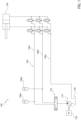
- FIG. 1 A simplified example of such hydraulic system is schematically represented in Figure 1 and is denoted as a whole with reference number 100.
- Hydraulic system comprises a hydraulic pump 110, which are carried by an internal combustion engine 120 and are configured to suck hydraulic fluid from a tank 130 and to provide at outlet a pressured flow of such hydraulic fluid.
- hydraulic system 100 comprises a hydraulic circuit 140, which fluidly connects pumping means 110 to at least one double-acting hydraulic cylinder 150, in order to feed to the same hydraulic cylinder 150 the hydraulic fluid provided at outlet.
- Hydraulic cylinder 150 may be, for instance, the boom actuator, the arm actuator or the bucket actuator of the aforementioned work machine.
- hydraulic circuit 140 includes three separate hydraulic lines or constant pressure rails 140a, 140b and 140c, which are arranged in parallel to each other and are adapted to form a high-pressure rail, a medium-pressure rail and a low-pressure rail respectively.
- Low-pressure rail 140c is fluidly connected to tank 130.
- Medium-pressure rail 140b and high-pressure rail 140a are fluidly connected to the outlet of hydraulic pump 110.
- hydraulic system 100 comprises a pair of hydraulic accumulators 160a and 160b fluidly connected respectively to high-pressure rail 140a and medium-pressure rail 140b, and a valve 170, which is operatively interposed between the outlet of hydraulic pump 110 and high- and medium-pressure rails 140a and 140b, and is configured to control the pressurized hydraulic fluid fed towards the same high- and medium-pressure rails 140a and 140b.
- the above hydraulic system 100 allows to reduce waste of energy and allows some energy recovery by accumulating pressurized hydraulic fluid within the hydraulic accumulators 160a and 160b during operation of work machine, for instance during lowering of the hydraulically actuated work implement or during deceleration of the body, the same hydraulic architecture still poses several drawbacks and there is still plenty of room for improvements.
- Aim of the present invention is to satisfy the above-mentioned need in an optimized and cost-effective manner.
- number 1 denotes, as a whole, a work machine, in particular an earth-moving machine such as an excavator, a digger, a mechanical shovel or the like.
- Work machine 1 comprises a body 2 movable on the ground via ground engaging wheels or tracks (not illustrated).
- body 2 preferably comprises: a lower frame or undercarriage (not illustrated), which carries the ground engaging wheels or tracks to allow motion of body 2 with respect to the ground; and an upper frame (not illustrated) or superstructure, which is carried in a rotatable manner by lower frame preferably about a rotation axis orthogonal to the advancing plane of work machine 1, i.e. orthogonal to the ground.
- work machine preferably comprises an internal combustion engine 4, which is configured to provide torque to allow motion of the work machine 2, for instance by driving a hydraulic pump, which in turn is fluidly connected to hydraulic motors that drive in rotation the ground engaging wheels or tracks.
- work machine 1 comprises a hydraulically actuated work implement 6, which is carried by body 2 and is configured to perform multiple earth moving operations, such as digging, handling earth or gravel, loading trucks and/or similar operations.
- work implement 6 is rotatably carried by the upper frame of work machine 1.
- the hydraulically actuated work implement 6 preferably comprises: a boom rotatably carried by the body 2; a stick or arm or dipper rotatably carried by the boom; and a bucket and/or other similar tools rotatably carried by the arm.
- work machine 1 preferably comprises one or more hydraulic actuators 7, which are preferably carried by the hydraulically actuated work implement 6 and are configured to operate the hydraulically actuated work implement 6.
- the one or more hydraulic actuators 7 may be configured to rotate the boom, the arm and/or the bucket with respect their corresponding hinge points.
- such a hydraulic actuator 7 preferably comprises a double-acting hydraulic cylinder, in particular a two-chamber double-acting hydraulic cylinder.
- hydraulic actuator 7 preferably comprises a housing 8 which accommodates in a sliding and fluid tight manner a piston 9.
- the piston 9 defines within the housing 8 two opposite chamber 10a and 10b, which are adapted to contain pressurized hydraulic fluid and are configured to exert forces on the piston 9 opposite to each other.
- housing 8 is preferably provided with two openings/ports 11a and 11b, which allow to put the respective chamber 10a and 10b in fluid communication with the outside.
- hydraulic actuators 7 preferably comprise one or more boom actuators, configured to rotate the boom with respect to the body 2.
- hydraulic actuators 7 comprise two boom actuators arranged on opposite sides of the boom.
- hydraulic actuators 7 further comprises at least one arm actuator (not illustrated), which is carried by the arm and is configured to rotate the arm with respect to the boom.
- hydraulic actuators 7 preferably comprise also at least one bucket actuator (not illustrated), which is preferably carried by the arm and is configured to rotate the bucket with respect to the arm.
- work machine 1 further comprise a hydraulic arrangement 14, which is fluidly connected to hydraulic actuator 7 and is configured to actuate this latter, in order to operate said work implement accordingly.
- hydraulic arrangement 14 is carried by body 2 and is adapted to be fluidly connected to hydraulic actuator 7 by means of hydraulic lines 15, in particular by means of flexible hydraulic hoses 15.
- hydraulic lines 15 preferably comprises a line or hose 15a configured to be fluidly connected to opening 11a of hydraulic actuator 7 and a line or hose 15b configured to be fluidly connected to opening 11b of hydraulic actuator 7.
- hydraulic arrangement 14 preferably comprises a source of pressurized hydraulic fluid 17, which is configured to provide at outlet a flow of pressurized hydraulic fluid.
- the source of pressurized hydraulic fluid preferably comprises pumping means 17, which are carried by internal combustion engine 4 and are configured to suck hydraulic fluid from a tank 18 and to provide at outlet a pressurized flow of such hydraulic fluid.
- hydraulic arrangement 14 further comprises a hydraulic circuit 20 which is adapted to put the outlet of the source of pressurized fluid, i.e. of pumping means 17 in fluid communication with the hydraulic actuator 7.
- the hydraulic circuit 20 is preferably provided with a common pressure rails (CPR) configuration, i.e. it comprises a plurality of separate hydraulic lines/ pipes/rails/conduits 21, which are arranged in parallel to each other and are each configured to be fluidly connected between the source of pressurized fluid and hydraulic actuator 7.
- CPR common pressure rails
- hydraulic lines 21 of hydraulic circuit are selectively connectable to hydraulic actuator 7, in particular to both chambers 10a and 10b of hydraulic actuator 7.
- hydraulic lines 21 of hydraulic circuit 20 are preferably configured to operate with a pressure setting which is constant and is different to each other, in order each to be able to provide pressurized hydraulic fluid to hydraulic actuator 7 with different pressure levels.
- hydraulic circuit 20 comprises at least two lines 21, which are arranged in parallel to each other and are adapted to fluidly connect the source of pressurized fluid with hydraulic actuator 7.
- the first one between the two lines 21 is connected to pumping means 17, while the second is preferably connected to tank 18.
- the first one between lines 21 will define a high-pressure line and the other one between lines 21 will define a low-pressure line.
- hydraulic circuit comprises at least three lines 21a, 21b and 21c arranged in parallel to each other.
- Lines 21a and 21b are preferably connected to the outlet of pumping means 17, while line 21c is preferably connected to tank 18 and preferably comprises filtering means 19.
- hydraulic arrangement 4 further comprises a control valve arrangement 22, which is fluidly interposed between hydraulic circuit 20 and hydraulic actuator 7, and is configured to regulate the flow of pressurized hydraulic fluid fed toward the same hydraulic actuator 7.
- control valve arrangement 22 configured to selectively put at least the high-pressure line 21a and/or the low-pressure line 21c in fluid communication with chamber 10a and/or chamber 10b of hydraulic actuator 7.
- control valve arrangement 22 is configured to allow to selectively fluidly connect the chambers 10a and 10b of hydraulic actuator 7 with lines 21 of hydraulic circuit 20.
- control valve arrangement 22 is preferably carried by body 2.
- Control valve arrangement 22 is preferably configured to be fluidly connected to hydraulic actuator 7 via hydraulic lines 15.
- control valve arrangement 22 comprises a first valve set 23 configured to selectively put the lines of hydraulic circuit 20 in fluid communication with chamber 10a of hydraulic actuator 7 and a second valve set 24 configured to selectively put the lines of hydraulic circuit 20 in fluid communication with chamber 10a of hydraulic actuator 7.
- each valve set 23 or 24 may comprise as many valves as many lines 21 there are provided within hydraulic circuit 20.
- valves of first valve set 23 and of second valve set 24 may comprise solenoid-controlled two-way two-position valves, for instance solenoid-controlled two-way two-position on-off valves or solenoid-controlled two-way two-position proportional valves, which are operable independently to each other and are operable between an open position and a closed position, to selectively fluidly connect respective lines 21a, 21b or 21c with respective chambers 10a or 10b of hydraulic actuator 7.
- solenoid-controlled two-way two-position valves for instance solenoid-controlled two-way two-position on-off valves or solenoid-controlled two-way two-position proportional valves, which are operable independently to each other and are operable between an open position and a closed position, to selectively fluidly connect respective lines 21a, 21b or 21c with respective chambers 10a or 10b of hydraulic actuator 7.
- hydraulic arrangement 14 further comprises at least one hydraulic accumulator 26, which is fluidly connected to hydraulic circuit 20, preferably upstream control valve arrangement 22.
- hydraulic accumulator 26 is preferably fluidly connected to the first one between lines 21, i.e. to the a high-pressure line 21a.
- hydraulic arrangement preferably comprises a first hydraulic accumulator 27, in the following referred to as "high-pressure hydraulic accumulator 27" fluidly connected to high-pressure line 21a and a second hydraulic accumulator 28, in the following referred to as “medium-pressure hydraulic accumulator 28" fluidly connected to medium-pressure line 21b.
- hydraulic arrangement 14 may comprise one hydraulic accumulator 26 for each hydraulic line 21 of hydraulic circuit 20, apart from low-pressure hydraulic line 21c, which may be not provided with a hydraulic accumulator 26.
- the one or more hydraulic accumulators 26 preferably comprises housing 29, in particular a cylindrical housing 29, accommodating in a fluid tight and sliding manner at least one piston assembly or septum 30, which defines two opposing chambers 31a and 31b within housing 29 fluidly separated to each other.
- first chamber 31a is preferably delimited between one end of housing 29 and piston assembly 30, in particular a first piston 30, and second chamber 31b is preferably delimited between a second end, opposite to the first, of housing 29 and the piston assembly 30.
- First chamber 31a is preferably fluidly connected to hydraulic circuit 20.
- first chamber 31a of high-pressure hydraulic accumulator 27 is preferably fluidly connected to high-pressure line 21a of hydraulic circuit 20, and first chamber 31a of medium-pressure hydraulic accumulator 28 is preferably fluidly connected to medium-pressure line 21b of hydraulic circuit 20.
- first chamber 31a of hydraulic accumulator 26, in particular of high-pressure hydraulic accumulators 27 and medium-pressure hydraulic accumulators 28, is preferably configured to contain pressurized hydraulic fluid, in particular oil.
- Second chamber 31b of hydraulic accumulator 26, in particular of high-pressure hydraulic accumulators 27 and medium-pressure hydraulic accumulators 28, is preferably fluidly connected to the source of pressurized hydraulic fluid, i.e. to pumping means 17, in order to be charged with hydraulic fluid, preferably oil, and vary/regulate the preload of the same hydraulic accumulator 26.
- the technical effect associated to the variation of the pressure within chambers 31a and 31b of hydraulic accumulator 26 is related to the possibility of regulating the pressure within the line 21 fluidly connected to the same accumulator.
- the one or more hydraulic accumulators 26, in particular high-pressure hydraulic accumulator 27 and medium-pressure hydraulic accumulator 28, preferably include double double-piston accumulators.
- piston assembly 30 may comprise a pair of pistons or septa, which are arranged in a sliding and fluid tight manner within housing 29 and are spaced to each other.
- the two pistons of piston assembly 30 preferably defines within housing 29 a third chamber 31c fluidly separated from the two chambers 31a and 31b.
- Third chamber 31c of hydraulic accumulator 26, in particular of high-pressure hydraulic accumulators 27 and medium-pressure hydraulic accumulators 28, is preferably configured to contain pressurized gas.
- third chambers 31c of hydraulic accumulator 26, in particular of high-pressure hydraulic accumulators 27 and medium-pressure hydraulic accumulators 28, is preferably sealed and preferably contains pressurized gas at a predetermined pressure.
- the source of pressurized hydraulic fluid 17, i.e. pumping means 17, preferably comprises a hydraulic pump 34, which is preferably carried by internal combustion engine 4 in order to be driven in rotation.
- hydraulic pump 34 is variable displacement hydraulic pump.
- outlet of hydraulic pump 34 is fluidly connected at least to the first hydraulic line of hydraulic circuit 20 and to first chamber 31a of accumulator 26.
- the outlet of hydraulic pump 34 is preferably fluidly connected to high-pressure line 21a and medium pressure line 21c, and also to first chamber 31a of high-pressure hydraulic accumulator 27 and medium-pressure hydraulic accumulator 28.
- hydraulic arrangement 14 preferably comprises valve means 38, which are operatively interposed between the source of pressurized hydraulic fluid 17 and the first hydraulic line of hydraulic circuit 20 and to first chamber 31a of accumulator 26.
- Valve means 38 are configured to control the flow of hydraulic fluid provided at outlet the source of pressurized hydraulic fluid 17, i.e. by hydraulic pump 34, and flowing through the same first hydraulic line towards hydraulic accumulator 26.
- valve means 38 are preferably fluidly interposed between the outlet of hydraulic pump 34 and high-pressure line 21a and medium pressure line 21c, and respectively also to first chamber 31a of high-pressure hydraulic accumulator 27 and medium-pressure hydraulic accumulator 28.
- valve means 38 are preferably configured to selectively fluidly connect high-pressure line 21a and medium pressure line 21c to the outlet of hydraulic pump 34, in particular to alternatively fluidly connect one between high-pressure hydraulic line 21a and medium-pressure hydraulic line 21b to the outlet of hydraulic pump 34.
- valve means 38 preferably comprises a three-way three-position hydraulic valve 40, in particular a solenoid controlled three-way three-position hydraulic valve 40.
- the three openings of hydraulic valve 40 are preferably fluidly connected to the outlet of hydraulic pump 34, to high-pressure hydraulic line 21a and to medium-pressure hydraulic line 21b.
- hydraulic valve 40 is configured to put the outlet of hydraulic pump 34 in fluid communication with high-pressure hydraulic line 21a and to fluidly isolate medium-pressure hydraulic line 21b from hydraulic pump 34.
- hydraulic valve 40 is configured to put the outlet of hydraulic pump 34 in fluid communication with medium-pressure hydraulic line 21b and to fluidly isolate high-pressure hydraulic line 21a from hydraulic pump 34.
- hydraulic valve 40 is configured to fluidly separate its ports, i.e. to fluidly separate medium-pressure hydraulic line 21b and high-pressure hydraulic line 21a from the outlet of hydraulic pump 34.
- hydraulic arrangement 14 further comprises at least one charging line 41 fluidly connecting the source of pressurized hydraulic fluid 17, i.e. pumping means 17, with the second chamber 31b of hydraulic accumulator 26, in order to allow to fed pressurized hydraulic fluid within second chamber 31b of hydraulic accumulator 26.
- charging line 41 is preferably fluidly connected to the outlet of hydraulic pump 34.
- hydraulic arrangement 14 preferably comprises a first charging line 41a, in the following referred to as "high-pressure charging line 41a", fluidly connecting the source of pressurized hydraulic fluid 17 with the second chamber 31b of high-pressure hydraulic accumulator 27.
- hydraulic arrangement 14 preferably comprises a second charging line 41b, in the following referred to as "medium-pressure charging line 41b", fluidly connecting the source of pressurized hydraulic fluid 17 with the second chamber 31b of medium-pressure hydraulic accumulator 28.
- hydraulic arrangement 14 preferably comprises valve means 43, which are operatively interposed between the source of pressurized hydraulic fluid 17 and second chamber 31b of accumulator 26 along charging line 41, and are configured to control the flow of pressurized hydraulic fluid flowing through the same charging line 41 towards the respective hydraulic accumulator 26.
- valve means 43 are preferably fluidly interposed between the source of pressurized hydraulic fluid 17 and high- and medium-pressure charging lines 41a and 41b, and are configured to selectively fluidly connect these latter to the source of pressurized hydraulic fluid 17, in particular to alternatively fluidly connected one between high-pressure charging line 41a and medium-pressure charging line 41b to the source of pressurized hydraulic fluid 17.
- hydraulic line 41 preferably branches off in a high-pressure charging line 41a fluidly connected to the second chamber of high-pressure hydraulic accumulator 27 and in a medium-pressure charging line 41b fluidly connected to the second chamber of medium-pressure hydraulic accumulator 28.
- valve means 43 preferably comprises a three-way three-position hydraulic valve 45, in particular a solenoid controlled three-way three-position hydraulic valve 45.
- valve 45 is a proportional valve 45.
- the three openings of hydraulic valve 45 are preferably fluidly connected to the source of pressurized hydraulic fluid 17, in particular to the outlet of hydraulic pump 34, to high-pressure charging line 41a and to medium-pressure charging line 41b.
- hydraulic valve 45 is configured to put the source of pressurized hydraulic fluid 17 in fluid communication with high-pressure charging line 41a and to fluidly isolate medium-pressure charging line 41b from the source of pressurized hydraulic fluid 17.
- hydraulic valve 45 is configured to put the source of pressurized hydraulic fluid 17 in fluid communication with medium-pressure charging line 41b and to fluidly isolate high-pressure charging line 41a from the source of pressurized hydraulic fluid 17.
- hydraulic valve 45 is configured to fluidly separate its ports, i.e. medium-pressure charging line 41b and high-pressure charging line 41a from the source of pressurized hydraulic fluid 17.
- charging line 41 and/or second chamber 31b of hydraulic accumulator 26, in particular of high-pressure hydraulic accumulator 27 and/or of medium-pressure hydraulic accumulator 28, is/are preferably selectively connectable to tank 18.
- charging line 41 is preferably selectively connectable to low-pressure line 21c.
- high-pressure charging line 41a and medium-pressure charging line 41b are preferably selectively connectable to low-pressure line 21c.
- hydraulic arrangement 14 preferably comprises valve means 47, which are operatively arranged along charging line 41, downstream hydraulic accumulator 26 and are configured to allow to selectively connect charging line 41 to tank 18, in particular to low-pressure line 21c.
- valve means 47 preferably comprises a two-way two-position hydraulic valve 48, in particular a solenoid controlled two-way two-position hydraulic valve 48.
- valve 48 is a proportional valve 48.
- valve means 48 preferably comprises a first hydraulic valve 48a arranged along high-pressure charging line 41a and a second hydraulic valve 48b arranged along medium-pressure charging line 41b, preferably downstream the respective high-pressure hydraulic accumulator 27 and medium-pressure hydraulic accumulator 28.
- hydraulic arrangement 14 preferably further comprises at least one additional hydraulic accumulator 50, which is fluidly connected to charging line 41, preferably between the source of pressurized hydraulic fluid 17, i.e. the outlet of hydraulic pump 34, and valve means 43.
- hydraulic arrangement 14 preferably comprises a check valve 51 and/or other similar valve means fluidly interposed between the outlet of pumping means 34 and the hydraulic accumulator 50.
- additional hydraulic accumulator 50 allows to fluidly decouple hydraulic pump 34 and the second chamber 31b of accumulator 26, in particular of high-pressure accumulator 27 and/or of medium-pressure accumulator 28.
- the second chamber 31b of accumulator 26, in particular of high- and medium-pressure accumulator 28 and 27, may be charged with the pressurized hydraulic fluid stored within additional hydraulic accumulator 50.
- hydraulic pump 34 may be operated to charge additional hydraulic accumulator 50.
- hydraulic arrangement 14 may be further provided with sensing means configured to measure the pressure of the hydraulic fluid present within hydraulic circuit 20.
- such sensing means may comprise pressure sensors 52a and 52b coupled at least to high- and medium- line 21a and 21b.
- such sensor means may further comprise pressure sensor 52c and 52d coupled to high- and medium-pressure charging line 41a and 41b.
- work machine 1 preferably further comprises an electronic control unit 60, which may be operatively connected to control valve arrangement 22, to valve means 38, 43 and/or 47, to pumping means 17 and is provided with elaboration means configured, in use, to control their operation.
- electronic control unit 60 which may be operatively connected to control valve arrangement 22, to valve means 38, 43 and/or 47, to pumping means 17 and is provided with elaboration means configured, in use, to control their operation.
- electronic control unit 60 may be operatively connected to said sensor means and may be configured to control operation of control valve arrangement 22, valve means 38, 43 and/or 47, and/or pumping means 17 based on the data provided by said sensor means.
- Hydraulic pump 34 is controlled to provide at outlet a pressurized flow of hydraulic fluid and valve means 38 are controlled to selectively charge high-pressure line 21a and first chamber 31a of accumulator 27 so that the hydraulic fluid within high-pressure line 21a, i.e. high-pressure rail, reaches a predetermined level.
- hydraulic pump 34 is controlled to provide at outlet a pressurized flow of hydraulic fluid and valve means 38 are controlled to selectively charge medium-pressure line 21b and first chamber 31a of medium-pressure accumulator 28, so that the hydraulic fluid within high-pressure line 21a, i.e. high-pressure rail, reaches a predetermined level.
- valve means 43 are controlled to charge the second chambers 31b of high- and medium-pressure accumulators 27 and 28, in order to control the preload of such hydraulic accumulators.
- valve means 43 and valve means 47 By controlling operation of hydraulic pump 34, valve means 43 and valve means 47, it is possible to control the pressure level within second chambers 31b of high- and medium-pressure accumulators 27 and 28, and accordingly within second chambers 31b of high- and medium-pressure accumulators 27 and 28 and high- and medium-pressure line 21a and 21b.
- the present invention is further directed to a method for controlling hydraulic arrangement 14.
- the method comprises the following steps:
- step a) preferably comprises the step of determining the pressure of the hydraulic fluid within the high- and medium-pressure line 21a and 21b.
- step a) may further comprise the step of determining the pressure of the hydraulic fluid within charging line 41, in particular within high- and medium-pressure charging line 41a and 41b.
- Steb b) in addition may comprise the step of controlling the displacement of main pumps 34 and/or the actuation of valve means 38, 43 and 47, so that the pressure of the hydraulic fluid within first chamber 31a and second chamber 31b of accumulator 36, in particular of high- and medium-pressure accumulator 27 and 28 is within a first and a second predetermined interval.
- the first predetermined interval is higher than the second predetermined interval.
- a double-chamber hydraulic accumulator 26 and of a dedicated charging line 41 allows, in use, to obtain a precise and fast control of the pressure levels within high-pressure line 21a and medium-pressure line 21b, in order to obtain a precise and fast response of the hydraulic circuit 20 to the actual flowrate and pressure demand required at hydraulic actuator 7.
- the pressure levels within the same high-pressure line 21a and medium-pressure line 21b may be controlled also controlling the pressure of the hydraulic fluid stored within chambers 31b of hydraulic accumulators 26, which in turn is controlled by controlling valve means 43.
- hydraulic circuit 20 may be higher, for instance hydraulic circuit 20 may comprise four or more different hydraulic lines 21 arranged in parallel to each other.
- hydraulic circuit may comprise as many hydraulic accumulators 26 as many different lines 21 there are provided within hydraulic circuit 20, apart from low-pressure line 21c which may not be provided with a hydraulic accumulator 26.
- Figure 3 illustrates a hydraulic arrangement 214, which is similar to hydraulic arrangement 14 and whose corresponding parts will be denoted with the same reference numbers as hydraulic arrangement 14.
- Hydraulic arrangement 214 distinguishes from hydraulic arrangement 14 in that charging line 41 is not connected to the outlet of hydraulic pump 34, and in that it further comprises a second hydraulic pump 234, referred also to as “charging pump 234", which is fluidly connected to charging line 41.
- charging pump 234 is preferably arranged in parallel to hydraulic pump 34.
- charging pump 234 is preferably carried by internal combustion engine 4 and is adapted to suck hydraulic fluid from tank 18 and to provide at outlet a pressurized flow of hydraulic fluid, towards charging line 41.
- charging pump 234 is a variable displacement pump.
Landscapes
- Engineering & Computer Science (AREA)
- General Engineering & Computer Science (AREA)
- Physics & Mathematics (AREA)
- Fluid Mechanics (AREA)
- Mechanical Engineering (AREA)
- Mining & Mineral Resources (AREA)
- Civil Engineering (AREA)
- Structural Engineering (AREA)
- Chemical & Material Sciences (AREA)
- Analytical Chemistry (AREA)
- Fluid-Pressure Circuits (AREA)
Abstract
the hydraulic accumulator (26, 28) comprises a first chamber (31a) connected to the first hydraulic line (21a) and a second preload chamber (31b), opposite to the first chamber (31a), connected to pumping means (17).
Description
- The present invention relates to a hydraulic arrangement for a work machine, in particular for an earth-moving machine such as an excavator, a digger, a mechanical shovel or the like. The present invention further relates to the control method of such hydraulic arrangement and to a work machine comprising such hydraulic arrangement.
- The present invention finds its preferred, although not exclusive, application in a hydraulic arrangement provided with a common pressure rails (CPR) configuration and adapted to control at least one hydraulic actuator of a hydraulically actuated arm of a work machine, in particular an excavator. Reference will be made to this application by way of the example below, without however losing in generality.
- As is known, work machines such as excavators, diggers, mechanical shovel or the like are provided with a hydraulically actuated work implement carried by a body of the work machine and configured to perform multiple earth-moving operations.
- In particular, such hydraulic actuated work implement usually comprises: a boom rotatably carried by the body of the work machine; a stick or dipper or arm rotatably carried by the boom; a bucket or similar work attachment rotatably carried by the arm; and a plurality of hydraulic actuators adapted to rotate the boom, the arm, and the bucket with respect to their hinge points.
- In addition, such work machines comprise a hydraulic system, which is configured to provide pressurized hydraulic fluid towards at least one of the aforementioned hydraulic actuators, in order to operate the latter.
- Traditionally, such hydraulic system comprises a source of pressurized hydraulic fluid and directional proportional control valves configured to throttle the flow of hydraulic fluid provided to each hydraulic actuator, to control its operation. This allows a precise control of the operation of each hydraulic actuator, but unfortunately results in a great deal of hydraulic fluid routed back to tank, with the waste in energy that this entails.
- To reduce waste of energy and allow some energy recovery, some manufacturer recently developed hydraulic systems including a hydraulic circuit provided with a common pressure rails (CPR) configuration, i.e. comprising a plurality of discrete pressure lines arranged in parallel to each other.
- In addition, such hydraulic system comprises a set of logic on-off hydraulic valve configured to selectively fluidly connect the hydraulic actuator to a source of pressurized hydraulic fluid.
- A simplified example of such hydraulic system is schematically represented in
Figure 1 and is denoted as a whole withreference number 100. - Hydraulic system comprises a
hydraulic pump 110, which are carried by aninternal combustion engine 120 and are configured to suck hydraulic fluid from atank 130 and to provide at outlet a pressured flow of such hydraulic fluid. - In addition,
hydraulic system 100 comprises ahydraulic circuit 140, which fluidly connects pumping means 110 to at least one double-actinghydraulic cylinder 150, in order to feed to the samehydraulic cylinder 150 the hydraulic fluid provided at outlet.Hydraulic cylinder 150 may be, for instance, the boom actuator, the arm actuator or the bucket actuator of the aforementioned work machine. - More in detail,
hydraulic circuit 140 includes three separate hydraulic lines orconstant pressure rails pressure rail 140c is fluidly connected totank 130. Medium-pressure rail 140b and high-pressure rail 140a, on the other hand, are fluidly connected to the outlet ofhydraulic pump 110. - In addition,
hydraulic system 100 comprises a pair ofhydraulic accumulators pressure rail 140a and medium-pressure rail 140b, and avalve 170, which is operatively interposed between the outlet ofhydraulic pump 110 and high- and medium-pressure rails pressure rails - Although the above
hydraulic system 100 allows to reduce waste of energy and allows some energy recovery by accumulating pressurized hydraulic fluid within thehydraulic accumulators - In particular, in the above-described
hydraulic system 100, it is not possible to optimize in real-time and to quickly adapt the pressure of the hydraulic fluid within high- and medium-pressure rails hydraulic actuator 150, and therefore to minimize the throttling losses. - In view of the above, the need is felt to provide an improved hydraulic arrangement for a work machine able to overcome the aforementioned drawbacks.
- Aim of the present invention is to satisfy the above-mentioned need in an optimized and cost-effective manner.
- The aforementioned aims are reached by an hydraulic arrangement, by a work machine and by a method as claimed in the appended set of claims.
- For a better understanding of the present invention, a preferred embodiment is described in the following, by way of a non-limiting example, with reference to the attached drawings, wherein:
-
Figure 1 is a schematic illustration of a hydraulic system for a hydraulically actuated work implement of a work machine as known in the art; -
Figure 2 ,3 are schematic illustrations of as many embodiments of a work machine realized according to the present invention, with parts removed for clarity. - With reference to
Figure 2 ,number 1 denotes, as a whole, a work machine, in particular an earth-moving machine such as an excavator, a digger, a mechanical shovel or the like. -
Work machine 1 comprises abody 2 movable on the ground via ground engaging wheels or tracks (not illustrated). - In particular,
body 2 preferably comprises: a lower frame or undercarriage (not illustrated), which carries the ground engaging wheels or tracks to allow motion ofbody 2 with respect to the ground; and an upper frame (not illustrated) or superstructure, which is carried in a rotatable manner by lower frame preferably about a rotation axis orthogonal to the advancing plane ofwork machine 1, i.e. orthogonal to the ground. - In addition, work machine preferably comprises an internal combustion engine 4, which is configured to provide torque to allow motion of the
work machine 2, for instance by driving a hydraulic pump, which in turn is fluidly connected to hydraulic motors that drive in rotation the ground engaging wheels or tracks. - In addition,
work machine 1 comprises a hydraulically actuatedwork implement 6, which is carried bybody 2 and is configured to perform multiple earth moving operations, such as digging, handling earth or gravel, loading trucks and/or similar operations. In particular,work implement 6 is rotatably carried by the upper frame ofwork machine 1. - As known, the hydraulically actuated work implement 6 preferably comprises: a boom rotatably carried by the
body 2; a stick or arm or dipper rotatably carried by the boom; and a bucket and/or other similar tools rotatably carried by the arm. - In addition,
work machine 1 preferably comprises one or more hydraulic actuators 7, which are preferably carried by the hydraulically actuatedwork implement 6 and are configured to operate the hydraulically actuatedwork implement 6. - In particular, the one or more hydraulic actuators 7 may be configured to rotate the boom, the arm and/or the bucket with respect their corresponding hinge points.
- More in detail, such a hydraulic actuator 7 preferably comprises a double-acting hydraulic cylinder, in particular a two-chamber double-acting hydraulic cylinder.
- With reference to the exemplary embodiment illustrated in
Figure 2 , in particular, hydraulic actuator 7 preferably comprises ahousing 8 which accommodates in a sliding and fluid tight manner a piston 9. The piston 9 defines within thehousing 8 twoopposite chamber - In addition,
housing 8 is preferably provided with two openings/ports respective chamber - With reference to a possible embodiment, hydraulic actuators 7 preferably comprise one or more boom actuators, configured to rotate the boom with respect to the
body 2. Preferably, hydraulic actuators 7 comprise two boom actuators arranged on opposite sides of the boom. - Preferably, hydraulic actuators 7 further comprises at least one arm actuator (not illustrated), which is carried by the arm and is configured to rotate the arm with respect to the boom.
- In addition, hydraulic actuators 7 preferably comprise also at least one bucket actuator (not illustrated), which is preferably carried by the arm and is configured to rotate the bucket with respect to the arm.
- With reference to the preferred embodiment illustrated in
Figure 2 ,work machine 1 further comprise ahydraulic arrangement 14, which is fluidly connected to hydraulic actuator 7 and is configured to actuate this latter, in order to operate said work implement accordingly. - In particular,
hydraulic arrangement 14 is carried bybody 2 and is adapted to be fluidly connected to hydraulic actuator 7 by means ofhydraulic lines 15, in particular by means of flexiblehydraulic hoses 15. - With reference to the exemplary embodiment illustrated in
Figure 2 ,hydraulic lines 15 preferably comprises a line orhose 15a configured to be fluidly connected to opening 11a of hydraulic actuator 7 and a line orhose 15b configured to be fluidly connected to opening 11b of hydraulic actuator 7. - In addition,
hydraulic arrangement 14 preferably comprises a source of pressurizedhydraulic fluid 17, which is configured to provide at outlet a flow of pressurized hydraulic fluid. - More in detail, the source of pressurized hydraulic fluid preferably comprises
pumping means 17, which are carried by internal combustion engine 4 and are configured to suck hydraulic fluid from atank 18 and to provide at outlet a pressurized flow of such hydraulic fluid. - With reference to the exemplary embodiment illustrated in
Figure 2 ,hydraulic arrangement 14 further comprises ahydraulic circuit 20 which is adapted to put the outlet of the source of pressurized fluid, i.e. of pumping means 17 in fluid communication with the hydraulic actuator 7. - More in detail, the
hydraulic circuit 20 is preferably provided with a common pressure rails (CPR) configuration, i.e. it comprises a plurality of separate hydraulic lines/ pipes/rails/conduits 21, which are arranged in parallel to each other and are each configured to be fluidly connected between the source of pressurized fluid and hydraulic actuator 7. - That is, all the
hydraulic lines 21 of hydraulic circuit are selectively connectable to hydraulic actuator 7, in particular to bothchambers - In particular, according to the CPR configuration,
hydraulic lines 21 ofhydraulic circuit 20 are preferably configured to operate with a pressure setting which is constant and is different to each other, in order each to be able to provide pressurized hydraulic fluid to hydraulic actuator 7 with different pressure levels. - More in detail,
hydraulic circuit 20 comprises at least twolines 21, which are arranged in parallel to each other and are adapted to fluidly connect the source of pressurized fluid with hydraulic actuator 7. - Preferably, the first one between the two
lines 21 is connected to pumping means 17, while the second is preferably connected totank 18. - Accordingly, in operation, the first one between
lines 21 will define a high-pressure line and the other one betweenlines 21 will define a low-pressure line. - In particular, with reference to the example illustrated in
Figure 2 , hydraulic circuit comprises at least threelines -
Lines pumping means 17, whileline 21c is preferably connected totank 18 and preferably comprisesfiltering means 19. - With reference to the exemplary embodiment illustrated in
Figure 2 , hydraulic arrangement 4 further comprises acontrol valve arrangement 22, which is fluidly interposed betweenhydraulic circuit 20 and hydraulic actuator 7, and is configured to regulate the flow of pressurized hydraulic fluid fed toward the same hydraulic actuator 7. - More in detail,
control valve arrangement 22 configured to selectively put at least the high-pressure line 21a and/or the low-pressure line 21c in fluid communication withchamber 10a and/orchamber 10b of hydraulic actuator 7. - In other words, in operation
control valve arrangement 22 is configured to allow to selectively fluidly connect thechambers lines 21 ofhydraulic circuit 20. - In addition,
control valve arrangement 22 is preferably carried bybody 2.Control valve arrangement 22 is preferably configured to be fluidly connected to hydraulic actuator 7 viahydraulic lines 15. - According to a possible embodiment,
control valve arrangement 22 comprises a first valve set 23 configured to selectively put the lines ofhydraulic circuit 20 in fluid communication withchamber 10a of hydraulic actuator 7 and a second valve set 24 configured to selectively put the lines ofhydraulic circuit 20 in fluid communication withchamber 10a of hydraulic actuator 7. - More in detail, each valve set 23 or 24 may comprise as many valves as
many lines 21 there are provided withinhydraulic circuit 20. - For example, valves of first valve set 23 and of second valve set 24 may comprise solenoid-controlled two-way two-position valves, for instance solenoid-controlled two-way two-position on-off valves or solenoid-controlled two-way two-position proportional valves, which are operable independently to each other and are operable between an open position and a closed position, to selectively fluidly connect
respective lines respective chambers - With reference to the exemplary embodiment illustrated in
Figure 2 ,hydraulic arrangement 14 further comprises at least onehydraulic accumulator 26, which is fluidly connected tohydraulic circuit 20, preferably upstreamcontrol valve arrangement 22. - More in detail,
hydraulic accumulator 26 is preferably fluidly connected to the first one betweenlines 21, i.e. to the a high-pressure line 21a. - According to the exemplary embodiment illustrated in
Figure 2 , hydraulic arrangement preferably comprises a firsthydraulic accumulator 27, in the following referred to as "high-pressurehydraulic accumulator 27" fluidly connected to high-pressure line 21a and a secondhydraulic accumulator 28, in the following referred to as "medium-pressurehydraulic accumulator 28" fluidly connected to medium-pressure line 21b. - It is intended that according to the present invention,
hydraulic arrangement 14 may comprise onehydraulic accumulator 26 for eachhydraulic line 21 ofhydraulic circuit 20, apart from low-pressurehydraulic line 21c, which may be not provided with ahydraulic accumulator 26. - The one or more
hydraulic accumulators 26 preferably compriseshousing 29, in particular acylindrical housing 29, accommodating in a fluid tight and sliding manner at least one piston assembly orseptum 30, which defines two opposingchambers housing 29 fluidly separated to each other. - In particular,
first chamber 31a is preferably delimited between one end ofhousing 29 andpiston assembly 30, in particular afirst piston 30, andsecond chamber 31b is preferably delimited between a second end, opposite to the first, ofhousing 29 and thepiston assembly 30. -
First chamber 31a is preferably fluidly connected tohydraulic circuit 20. - More in detail, according to the exemplary embodiment illustrated in
Figure 2 ,first chamber 31a of high-pressurehydraulic accumulator 27 is preferably fluidly connected to high-pressure line 21a ofhydraulic circuit 20, andfirst chamber 31a of medium-pressurehydraulic accumulator 28 is preferably fluidly connected to medium-pressure line 21b ofhydraulic circuit 20. - Preferably,
first chamber 31a ofhydraulic accumulator 26, in particular of high-pressurehydraulic accumulators 27 and medium-pressurehydraulic accumulators 28, is preferably configured to contain pressurized hydraulic fluid, in particular oil. -
Second chamber 31b ofhydraulic accumulator 26, in particular of high-pressurehydraulic accumulators 27 and medium-pressurehydraulic accumulators 28, is preferably fluidly connected to the source of pressurized hydraulic fluid, i.e. to pumping means 17, in order to be charged with hydraulic fluid, preferably oil, and vary/regulate the preload of the samehydraulic accumulator 26. - More in detail, by varying the pressure within
second chamber 31b ofhydraulic accumulator 26, the pressure withinfirst chamber 31a of the samehydraulic accumulator 26 will vary accordingly. - The technical effect associated to the variation of the pressure within
chambers hydraulic accumulator 26 is related to the possibility of regulating the pressure within theline 21 fluidly connected to the same accumulator. - In particular, by varying the pressure within high-pressure
hydraulic accumulators 27 and medium-pressurehydraulic accumulators 28, it is possible to regulate the pressure within high-pressure line 21a and medium-pressure line 21b respectively. - With reference to the exemplary embodiment illustrated in
Figure 2 , the one or morehydraulic accumulators 26, in particular high-pressurehydraulic accumulator 27 and medium-pressurehydraulic accumulator 28, preferably include double double-piston accumulators. - In other words,
piston assembly 30 may comprise a pair of pistons or septa, which are arranged in a sliding and fluid tight manner withinhousing 29 and are spaced to each other. The two pistons ofpiston assembly 30 preferably defines within housing 29 athird chamber 31c fluidly separated from the twochambers -
Third chamber 31c ofhydraulic accumulator 26, in particular of high-pressurehydraulic accumulators 27 and medium-pressurehydraulic accumulators 28, is preferably configured to contain pressurized gas. - In addition,
third chambers 31c ofhydraulic accumulator 26, in particular of high-pressurehydraulic accumulators 27 and medium-pressurehydraulic accumulators 28, is preferably sealed and preferably contains pressurized gas at a predetermined pressure. - With reference to the exemplary embodiment illustrated in
Figure 2 , as far as the source of pressurizedhydraulic fluid 17, i.e. pumping means 17, is concerned, it preferably comprises ahydraulic pump 34, which is preferably carried by internal combustion engine 4 in order to be driven in rotation. - Preferably,
hydraulic pump 34 is variable displacement hydraulic pump. - In addition, the outlet of
hydraulic pump 34 is fluidly connected at least to the first hydraulic line ofhydraulic circuit 20 and tofirst chamber 31a ofaccumulator 26. - More in detail, with reference to the exemplary embodiment illustrated in
Figure 2 , the outlet ofhydraulic pump 34 is preferably fluidly connected to high-pressure line 21a andmedium pressure line 21c, and also tofirst chamber 31a of high-pressurehydraulic accumulator 27 and medium-pressurehydraulic accumulator 28. - In addition,
hydraulic arrangement 14 preferably comprises valve means 38, which are operatively interposed between the source of pressurizedhydraulic fluid 17 and the first hydraulic line ofhydraulic circuit 20 and tofirst chamber 31a ofaccumulator 26. - Valve means 38 are configured to control the flow of hydraulic fluid provided at outlet the source of pressurized
hydraulic fluid 17, i.e. byhydraulic pump 34, and flowing through the same first hydraulic line towardshydraulic accumulator 26. - More in detail, according to the example illustrated in
Figure 2 , valve means 38 are preferably fluidly interposed between the outlet ofhydraulic pump 34 and high-pressure line 21a andmedium pressure line 21c, and respectively also tofirst chamber 31a of high-pressurehydraulic accumulator 27 and medium-pressurehydraulic accumulator 28. - In addition, valve means 38 are preferably configured to selectively fluidly connect high-
pressure line 21a andmedium pressure line 21c to the outlet ofhydraulic pump 34, in particular to alternatively fluidly connect one between high-pressurehydraulic line 21a and medium-pressurehydraulic line 21b to the outlet ofhydraulic pump 34. - With reference to the exemplary embodiment illustrated in
Figure 2 , valve means 38 preferably comprises a three-way three-positionhydraulic valve 40, in particular a solenoid controlled three-way three-positionhydraulic valve 40. - The three openings of
hydraulic valve 40 are preferably fluidly connected to the outlet ofhydraulic pump 34, to high-pressurehydraulic line 21a and to medium-pressurehydraulic line 21b. - In the first position,
hydraulic valve 40 is configured to put the outlet ofhydraulic pump 34 in fluid communication with high-pressurehydraulic line 21a and to fluidly isolate medium-pressurehydraulic line 21b fromhydraulic pump 34. - In the second position,
hydraulic valve 40 is configured to put the outlet ofhydraulic pump 34 in fluid communication with medium-pressurehydraulic line 21b and to fluidly isolate high-pressurehydraulic line 21a fromhydraulic pump 34. - In third position,
hydraulic valve 40 is configured to fluidly separate its ports, i.e. to fluidly separate medium-pressurehydraulic line 21b and high-pressurehydraulic line 21a from the outlet ofhydraulic pump 34. - With reference to the exemplary embodiment illustrated in
Figure 2 , in addition,hydraulic arrangement 14 further comprises at least one chargingline 41 fluidly connecting the source of pressurizedhydraulic fluid 17, i.e. pumping means 17, with thesecond chamber 31b ofhydraulic accumulator 26, in order to allow to fed pressurized hydraulic fluid withinsecond chamber 31b ofhydraulic accumulator 26. - In particular, charging
line 41 is preferably fluidly connected to the outlet ofhydraulic pump 34. - More in detail, with reference to the exemplary embodiment illustrated in
Figure 2 ,hydraulic arrangement 14 preferably comprises afirst charging line 41a, in the following referred to as "high-pressure charging line 41a", fluidly connecting the source of pressurized hydraulic fluid 17 with thesecond chamber 31b of high-pressurehydraulic accumulator 27. - In addition,
hydraulic arrangement 14 preferably comprises asecond charging line 41b, in the following referred to as "medium-pressure charging line 41b", fluidly connecting the source of pressurized hydraulic fluid 17 with thesecond chamber 31b of medium-pressurehydraulic accumulator 28. - In addition,
hydraulic arrangement 14 preferably comprises valve means 43, which are operatively interposed between the source of pressurizedhydraulic fluid 17 andsecond chamber 31b ofaccumulator 26 along chargingline 41, and are configured to control the flow of pressurized hydraulic fluid flowing through thesame charging line 41 towards the respectivehydraulic accumulator 26. - More in detail, according to the exemplary embodiment illustrated in
Figure 2 , valve means 43 are preferably fluidly interposed between the source of pressurizedhydraulic fluid 17 and high- and medium-pressure charging lines hydraulic fluid 17, in particular to alternatively fluidly connected one between high-pressure charging line 41a and medium-pressure charging line 41b to the source of pressurizedhydraulic fluid 17. - In other words, downstream valve means 43,
hydraulic line 41 preferably branches off in a high-pressure charging line 41a fluidly connected to the second chamber of high-pressurehydraulic accumulator 27 and in a medium-pressure charging line 41b fluidly connected to the second chamber of medium-pressurehydraulic accumulator 28. - With reference to the exemplary embodiment illustrated in
Figure 2 , valve means 43 preferably comprises a three-way three-positionhydraulic valve 45, in particular a solenoid controlled three-way three-positionhydraulic valve 45. Preferably,valve 45 is aproportional valve 45. - The three openings of
hydraulic valve 45 are preferably fluidly connected to the source of pressurizedhydraulic fluid 17, in particular to the outlet ofhydraulic pump 34, to high-pressure charging line 41a and to medium-pressure charging line 41b. - In the first position,
hydraulic valve 45 is configured to put the source of pressurized hydraulic fluid 17 in fluid communication with high-pressure charging line 41a and to fluidly isolate medium-pressure charging line 41b from the source of pressurizedhydraulic fluid 17. - In the second position,
hydraulic valve 45 is configured to put the source of pressurized hydraulic fluid 17 in fluid communication with medium-pressure charging line 41b and to fluidly isolate high-pressure charging line 41a from the source of pressurizedhydraulic fluid 17. - In the third position,
hydraulic valve 45 is configured to fluidly separate its ports, i.e. medium-pressure charging line 41b and high-pressure charging line 41a from the source of pressurizedhydraulic fluid 17. - With reference to exemplary embodiment illustrated in
Figure 2 , chargingline 41 and/orsecond chamber 31b ofhydraulic accumulator 26, in particular of high-pressurehydraulic accumulator 27 and/or of medium-pressurehydraulic accumulator 28, is/are preferably selectively connectable totank 18. - More in detail, charging
line 41 is preferably selectively connectable to low-pressure line 21c. - In even more detail, high-
pressure charging line 41a and medium-pressure charging line 41b are preferably selectively connectable to low-pressure line 21c. - In addition,
hydraulic arrangement 14 preferably comprises valve means 47, which are operatively arranged along chargingline 41, downstreamhydraulic accumulator 26 and are configured to allow to selectively connect chargingline 41 totank 18, in particular to low-pressure line 21c. - With reference to the exemplary embodiment illustrated in
Figure 2 , valve means 47 preferably comprises a two-way two-positionhydraulic valve 48, in particular a solenoid controlled two-way two-positionhydraulic valve 48. Preferably,valve 48 is aproportional valve 48. - More in detail, valve means 48 preferably comprises a first
hydraulic valve 48a arranged along high-pressure charging line 41a and a secondhydraulic valve 48b arranged along medium-pressure charging line 41b, preferably downstream the respective high-pressurehydraulic accumulator 27 and medium-pressurehydraulic accumulator 28. - With reference to the exemplary embodiment illustrated in
Figure 2 ,hydraulic arrangement 14 preferably further comprises at least one additionalhydraulic accumulator 50, which is fluidly connected to chargingline 41, preferably between the source of pressurizedhydraulic fluid 17, i.e. the outlet ofhydraulic pump 34, and valve means 43. - In addition,
hydraulic arrangement 14 preferably comprises acheck valve 51 and/or other similar valve means fluidly interposed between the outlet of pumping means 34 and thehydraulic accumulator 50. - In particular, additional
hydraulic accumulator 50 allows to fluidly decouplehydraulic pump 34 and thesecond chamber 31b ofaccumulator 26, in particular of high-pressure accumulator 27 and/or of medium-pressure accumulator 28. - Accordingly, during operation, the
second chamber 31b ofaccumulator 26, in particular of high- and medium-pressure accumulator hydraulic accumulator 50. In addition, during operation,hydraulic pump 34 may be operated to charge additionalhydraulic accumulator 50. - With reference to the exemplary embodiment illustrated in
Figure 1 ,hydraulic arrangement 14 may be further provided with sensing means configured to measure the pressure of the hydraulic fluid present withinhydraulic circuit 20. - More in detail, such sensing means may comprise
pressure sensors line - In addition, such sensor means may further comprise
pressure sensor pressure charging line - With reference to the exemplary embodiment illustrated in
Figure 2 ,work machine 1 preferably further comprises anelectronic control unit 60, which may be operatively connected to controlvalve arrangement 22, to valve means 38, 43 and/or 47, to pumping means 17 and is provided with elaboration means configured, in use, to control their operation. - In particular,
electronic control unit 60 may be operatively connected to said sensor means and may be configured to control operation ofcontrol valve arrangement 22, valve means 38, 43 and/or 47, and/or pumping means 17 based on the data provided by said sensor means. - The operation of the above-described
hydraulic arrangement 14 is the following. -
Hydraulic pump 34 is controlled to provide at outlet a pressurized flow of hydraulic fluid and valve means 38 are controlled to selectively charge high-pressure line 21a andfirst chamber 31a ofaccumulator 27 so that the hydraulic fluid within high-pressure line 21a, i.e. high-pressure rail, reaches a predetermined level. - In addition,
hydraulic pump 34 is controlled to provide at outlet a pressurized flow of hydraulic fluid and valve means 38 are controlled to selectively charge medium-pressure line 21b andfirst chamber 31a of medium-pressure accumulator 28, so that the hydraulic fluid within high-pressure line 21a, i.e. high-pressure rail, reaches a predetermined level. - At the same time, valve means 43 are controlled to charge the
second chambers 31b of high- and medium-pressure accumulators - By controlling operation of
hydraulic pump 34, valve means 43 and valve means 47, it is possible to control the pressure level withinsecond chambers 31b of high- and medium-pressure accumulators second chambers 31b of high- and medium-pressure accumulators pressure line - In view of the foregoing, the present invention is further directed to a method for controlling
hydraulic arrangement 14. - The method comprises the following steps:
- a) determining the pressure of the hydraulic fluid within the first line of the
hydraulic circuit 20; and - b) controlling the operation of the source of pressurized
hydraulic fluid 17 and of valve means 38, 43 and/or 47 so that the pressure within the first line of thehydraulic circuit 20 is within a predetermined interval. - More in detail, step a) preferably comprises the step of determining the pressure of the hydraulic fluid within the high- and medium-
pressure line - In addition, step a) may further comprise the step of determining the pressure of the hydraulic fluid within charging
line 41, in particular within high- and medium-pressure charging line - Steb b) in addition may comprise the step of controlling the displacement of
main pumps 34 and/or the actuation of valve means 38, 43 and 47, so that the pressure of the hydraulic fluid withinfirst chamber 31a andsecond chamber 31b of accumulator 36, in particular of high- and medium-pressure accumulator - Preferably, the first predetermined interval is higher than the second predetermined interval.
- In view of the foregoing, the advantages of a
hydraulic arrangement 14 according to the present invention are considerable and apparent. - In particular, the provision of a double-chamber
hydraulic accumulator 26 and of adedicated charging line 41 allows, in use, to obtain a precise and fast control of the pressure levels within high-pressure line 21a and medium-pressure line 21b, in order to obtain a precise and fast response of thehydraulic circuit 20 to the actual flowrate and pressure demand required at hydraulic actuator 7. - In fact, the pressure levels within the same high-
pressure line 21a and medium-pressure line 21b may be controlled also controlling the pressure of the hydraulic fluid stored withinchambers 31b ofhydraulic accumulators 26, which in turn is controlled by controlling valve means 43. - In addition, according to the proposed layout, it is possible to increase the number of
hydraulic lines 21 within CPRhydraulic circuit 20 and the number of associatedhydraulic accumulators 26 without necessarily increasing the number of hydraulic pumps 34. In fact, if properly sized, only onehydraulic pump 34 may be enough for four or more differenthydraulic lines 21 withinhydraulic circuit 20. - Lastly, the provision of the additional
hydraulic accumulator 50 between the source of pressurizedhydraulic fluid 17 and valve means 43, along chargingline 41 allows to decouple the operation ofhydraulic pump 34 from the operation of thehydraulic accumulators 26, in particular of high-pressurehydraulic accumulator 27 and medium-pressurehydraulic accumulator 28, arranged downstream the additionhydraulic accumulator 26. - This allows to operate the internal combustion engine 4 and the
hydraulic pump 34 in their respective maximum efficiency intervals to charge thehydraulic accumulator 50, independently from the actual flow demand at the hydraulic actuators 7, thus allowing to reduce the overall fuel consumption ofwork machine 1. - It is clear that modifications can be made to the described
hydraulic arrangement 14, which do not extend beyond the scope of protection defined by the claims. - In particular, the number of
hydraulic lines 21 ofhydraulic circuit 20 may be higher, for instancehydraulic circuit 20 may comprise four or more differenthydraulic lines 21 arranged in parallel to each other. - Accordingly, also the number of
hydraulic accumulators 26 may be different. In particular, hydraulic circuit may comprise as manyhydraulic accumulators 26 as manydifferent lines 21 there are provided withinhydraulic circuit 20, apart from low-pressure line 21c which may not be provided with ahydraulic accumulator 26. - In addition,
Figure 3 illustrates ahydraulic arrangement 214, which is similar tohydraulic arrangement 14 and whose corresponding parts will be denoted with the same reference numbers ashydraulic arrangement 14. -
Hydraulic arrangement 214 distinguishes fromhydraulic arrangement 14 in that chargingline 41 is not connected to the outlet ofhydraulic pump 34, and in that it further comprises a secondhydraulic pump 234, referred also to as "chargingpump 234", which is fluidly connected to chargingline 41. - More in detail, charging
pump 234 is preferably arranged in parallel tohydraulic pump 34. - In addition, charging
pump 234 is preferably carried by internal combustion engine 4 and is adapted to suck hydraulic fluid fromtank 18 and to provide at outlet a pressurized flow of hydraulic fluid, towards chargingline 41. - Preferably, charging
pump 234 is a variable displacement pump.
Claims (12)
- A hydraulic arrangement (14, 214) for a work machine (1) ;said work machine (1) comprising: a body (2) movable on the ground by means of ground engaging means; and a hydraulically actuated work implement (6), which is rotatably carried by said body (2) and is configured to perform multiple earth moving operations;said hydraulic arrangement (14) comprising:• a source of pressurized hydraulic fluid (17), which is configured to suck hydraulic fluid from a tank (18) and to provide at outlet a pressurized flow of hydraulic fluid;• at least one hydraulic actuator (7), which is configured to operate said hydraulically actuated work implement (6) ;• a hydraulic circuit (20), which is configured to put said source of hydraulic fluid (17) in fluid communication with said hydraulic actuator (7); and• a control valve arrangement (22), which is operatively interposed between said hydraulic circuit (20) and said hydraulic actuator (7) and is configured to selectively put said hydraulic circuit (20) in fluid communication with said hydraulic actuator (7); andsaid hydraulic circuit (20) comprising:• a first hydraulic line (21a), which fluidly connects said source of pressurized hydraulic fluid (17) with said hydraulic actuator (7);• a second hydraulic line (21c), which is arranged in parallel to said first hydraulic line (21a) and fluidly connects said tank (18) with said hydraulic actuator (7); and• at least a first hydraulic accumulator (26, 27), which is fluidly connected to said first hydraulic line (21a), upstream said control valve arrangement (22);said first hydraulic accumulator (26, 27) comprising a housing (29) and a piston assembly (30), which is accommodated in a fluid-tight and slidable manner within said housing (29) and defines at least a first chamber (31a) and a second chamber (31b), opposite to said first chamber (31a);the first chamber (31a) of said first hydraulic accumulator being fluidly connected to said first hydraulic line (21a);the second chamber (31b) of said hydraulic accumulator (26, 27) being fluidly connected to said source of hydraulic fluid (17) via a charging line (41, 41a), which is arranged in parallel to said hydraulic circuit (20).
- Hydraulic arrangement according to claim 1, wherein said source of pressurized hydraulic fluid (17) comprises a first hydraulic pump (34) configured to be fluidly connected to said first hydraulic line (21a).
- Hydraulic arrangement according to claim 1 or 2, further comprising first valve means (38), which are operatively interposed between said source of pressurized hydraulic fluid (17) and said first hydraulic line (21a), and are configured to control the flow of pressurized hydraulic fluid flowing towards said first chamber (31a) of said first hydraulic accumulator (26, 27).
- Hydraulic arrangement according to claim 3, further comprising second valve means (43), which are operatively interposed between said source of pressurized hydraulic fluid (17) and the second chamber (31b) of said first hydraulic accumulator (26, 27), and are configured to control the flow of pressurized hydraulic fluid flowing towards said second chamber (31b) of said first hydraulic accumulator (26, 27).
- Hydraulic arrangement according to claim 4, further comprising an additional hydraulic accumulator (50), which is fluidly connected to said charging line (41), between said source of pressurized hydraulic fluid (17) and said second valve means (43).
- Hydraulic accumulator, according to claim 4 or 5, wherein said hydraulic circuit (20) further comprises:• a third hydraulic line (21b), which fluidly connects said source of pressurized hydraulic fluid (17) with said hydraulic actuator (7) and is arranged in parallel to said first hydraulic line (21a); and• a second hydraulic accumulator (26, 28), which is fluidly connected to said second hydraulic line (21b) upstream said control valve arrangement (22);said second hydraulic accumulator (26, 28) comprising a housing (29) and a piston assembly (30), which is accommodated in a fluid-tight and slidable manner within said housing (29) and defines at least a first chamber (31a) and a second chamber (31b), opposite to said first chamber (31a);the first chamber (31a) of said second hydraulic accumulator (28) being fluidly connected to said second hydraulic line (21b) ;the second chamber (31b) of said second hydraulic accumulator (28) being fluidly connected to said source of pressurized hydraulic fluid (17) via said charging line (41, 41b) .
- Hydraulic arrangement according to claim 6, wherein said charging line (41), downstream said second valve means (43) branches off in a first charging line (41a) fluidly connected to the second chamber of said first hydraulic accumulator (26, 28) and in a second charging line (41b) fluidly connected to the second chamber of said second hydraulic accumulator (26, 28).
- Hydraulic arrangement according to claim 6 or 7, wherein the piston assembly (30) of said first hydraulic actuator (26, 28) and/or of said second hydraulic accumulator (26, 28) comprises a pair of pistons/septa, which are arranged in a sliding and fluid tight manner within said housing (29) and are spaced from each other, in order to define within said housing (29) a third chamber (31c), which is fluidly separated from said first chamber (31a) and said second (31b) and is configured to contain pressurized gas.
- Hydraulic arrangement according to claim 6, 7 or 8, wherein said first valve means (38) and/or said second valve means (43) comprise a three-way three-position solenoid-controlled valve (40).
- Hydraulic arrangement according to any of claims from 2 to 9, wherein said source of pressurized hydraulic fluid (17) comprises a second hydraulic pump (234), which is arranged in parallel to said first hydraulic pump (34) and is configured to be fluidly connected to said charging line (41).
- A work machine (1) comprising: a body (2) movable on the ground by means of ground engaging means; a hydraulically actuated work implement (6), which is rotatably carried by said body (2) and is configured to perform multiple earth moving operations; and an hydraulic arrangement (14), which is realized according to any of the preceding claims.
- A method for controlling a hydraulic arrangement (14, 214) realized according to any of claims from 4 to 10, the method comprising the following steps:a) determining the pressure of the hydraulic fluid within said first hydraulic line (21a) of said hydraulic circuit (20); andb) controlling the operation of source of hydraulic fluid (17), said first valve means (38) and/or said second valve means (43) according to the pressure determined in step a), in order to maintain the pressure of the hydraulic fluid within said first hydraulic line (21a) within a predetermined interval.
Applications Claiming Priority (1)
| Application Number | Priority Date | Filing Date | Title |
|---|---|---|---|
| IT102023000014607A IT202300014607A1 (en) | 2023-07-12 | 2023-07-12 | IMPROVED HYDRAULIC SYSTEM FOR A WORKING MACHINE, METHOD OF CONTROL THEREOF AND WORKING MACHINERY INCLUDING SUCH HYDRAULIC SYSTEM |
Publications (1)
| Publication Number | Publication Date |
|---|---|
| EP4491809A1 true EP4491809A1 (en) | 2025-01-15 |
Family
ID=88098261
Family Applications (1)
| Application Number | Title | Priority Date | Filing Date |
|---|---|---|---|
| EP24188145.7A Pending EP4491809A1 (en) | 2023-07-12 | 2024-07-11 | Improved hydraulic arrangement for a work machine, control method thereof, and work machine comprising such hydraulic arrangement |
Country Status (2)
| Country | Link |
|---|---|
| EP (1) | EP4491809A1 (en) |
| IT (1) | IT202300014607A1 (en) |
Cited By (1)
| Publication number | Priority date | Publication date | Assignee | Title |
|---|---|---|---|---|
| US20250361889A1 (en) * | 2024-05-21 | 2025-11-27 | Wipro Enterprises Pvt, Ltd. | Actuator assembly for a heavy construction machine |
Citations (2)
| Publication number | Priority date | Publication date | Assignee | Title |
|---|---|---|---|---|
| JP2001295813A (en) * | 2000-04-12 | 2001-10-26 | Yanmar Diesel Engine Co Ltd | Hydraulic circuit of work machine |
| CN105714872A (en) * | 2014-08-08 | 2016-06-29 | 北京建筑大学 | Pressure-adjustable and capacity-adjustable hydraulic energy recycling and storing system and working method of hydraulic energy recycling and storing system |
-
2023
- 2023-07-12 IT IT102023000014607A patent/IT202300014607A1/en unknown
-
2024
- 2024-07-11 EP EP24188145.7A patent/EP4491809A1/en active Pending
Patent Citations (2)
| Publication number | Priority date | Publication date | Assignee | Title |
|---|---|---|---|---|
| JP2001295813A (en) * | 2000-04-12 | 2001-10-26 | Yanmar Diesel Engine Co Ltd | Hydraulic circuit of work machine |
| CN105714872A (en) * | 2014-08-08 | 2016-06-29 | 北京建筑大学 | Pressure-adjustable and capacity-adjustable hydraulic energy recycling and storing system and working method of hydraulic energy recycling and storing system |
Cited By (1)
| Publication number | Priority date | Publication date | Assignee | Title |
|---|---|---|---|---|
| US20250361889A1 (en) * | 2024-05-21 | 2025-11-27 | Wipro Enterprises Pvt, Ltd. | Actuator assembly for a heavy construction machine |
Also Published As
| Publication number | Publication date |
|---|---|
| IT202300014607A1 (en) | 2025-01-12 |
Similar Documents
| Publication | Publication Date | Title |
|---|---|---|
| JP6785203B2 (en) | Construction machinery | |
| US9932993B2 (en) | System and method for hydraulic energy recovery | |
| US7905089B2 (en) | Actuator control system implementing adaptive flow control | |
| US7441407B2 (en) | Hydraulic drive control device | |
| EP1801296A2 (en) | Hydraulic circuit system for hydraulic working machine | |
| JP2702646B2 (en) | Hydraulic circuit structure of backhoe device | |
| JP5297187B2 (en) | Hydraulic system with pressure compensator | |
| US11781289B2 (en) | Electro-hydraulic drive system for a machine | |
| JP2014502709A (en) | Energy recovery system for construction machinery | |
| US20160281330A1 (en) | Hydraulic System Recovering Swing Kinetic and Boom Potential Energy | |
| JP6663539B2 (en) | Hydraulic drive | |
| US20130081382A1 (en) | Regeneration configuration for closed-loop hydraulic systems | |
| JP5060734B2 (en) | Hydraulic system with variable back pressure control | |
| US11788256B2 (en) | Dual architecture for an electro-hydraulic drive system | |
| KR100248186B1 (en) | Hydraulic control system | |
| US10550547B2 (en) | Hydraulic systems for construction machinery | |
| EP3872354A1 (en) | Construction machine | |
| EP3686442A1 (en) | Fluid pressure control device | |
| CN106460877A (en) | Shovel and control method therefor | |
| IT202300014607A1 (en) | IMPROVED HYDRAULIC SYSTEM FOR A WORKING MACHINE, METHOD OF CONTROL THEREOF AND WORKING MACHINERY INCLUDING SUCH HYDRAULIC SYSTEM | |
| EP4491810A1 (en) | Improved hydraulic arrangement for a work machine and work machine comprising such hydraulic arrangement | |
| EP4495338A1 (en) | Improved work machine | |
| WO2010026677A1 (en) | Hydraulic control system in working machine | |
| EP4575104A1 (en) | Improved work machine | |
| CN112554251B (en) | Digging machine |
Legal Events
| Date | Code | Title | Description |
|---|---|---|---|
| PUAI | Public reference made under article 153(3) epc to a published international application that has entered the european phase |
Free format text: ORIGINAL CODE: 0009012 |
|
| STAA | Information on the status of an ep patent application or granted ep patent |
Free format text: STATUS: THE APPLICATION HAS BEEN PUBLISHED |
|
| AK | Designated contracting states |
Kind code of ref document: A1 Designated state(s): AL AT BE BG CH CY CZ DE DK EE ES FI FR GB GR HR HU IE IS IT LI LT LU LV MC ME MK MT NL NO PL PT RO RS SE SI SK SM TR |
|
| STAA | Information on the status of an ep patent application or granted ep patent |
Free format text: STATUS: REQUEST FOR EXAMINATION WAS MADE |
|
| 17P | Request for examination filed |
Effective date: 20250715 |
|
| GRAP | Despatch of communication of intention to grant a patent |
Free format text: ORIGINAL CODE: EPIDOSNIGR1 |
|
| STAA | Information on the status of an ep patent application or granted ep patent |
Free format text: STATUS: GRANT OF PATENT IS INTENDED |
|
| RIC1 | Information provided on ipc code assigned before grant |
Ipc: E02F 9/22 20060101AFI20260709BHEP |