EP4491794A2 - Roll weight system for on machine dynamic verification - Google Patents
Roll weight system for on machine dynamic verification Download PDFInfo
- Publication number
- EP4491794A2 EP4491794A2 EP24183001.7A EP24183001A EP4491794A2 EP 4491794 A2 EP4491794 A2 EP 4491794A2 EP 24183001 A EP24183001 A EP 24183001A EP 4491794 A2 EP4491794 A2 EP 4491794A2
- Authority
- EP
- European Patent Office
- Prior art keywords
- sheet
- roll
- weight
- spool
- wound
- Prior art date
- Legal status (The legal status is an assumption and is not a legal conclusion. Google has not performed a legal analysis and makes no representation as to the accuracy of the status listed.)
- Pending
Links
Images


Classifications
-
- D—TEXTILES; PAPER
- D21—PAPER-MAKING; PRODUCTION OF CELLULOSE
- D21G—CALENDERS; ACCESSORIES FOR PAPER-MAKING MACHINES
- D21G9/00—Other accessories for paper-making machines
-
- G—PHYSICS
- G01—MEASURING; TESTING
- G01G—WEIGHING
- G01G23/00—Auxiliary devices for weighing apparatus
- G01G23/14—Devices for determining tare weight or for cancelling out the tare by zeroising, e.g. mechanically operated
- G01G23/16—Devices for determining tare weight or for cancelling out the tare by zeroising, e.g. mechanically operated electrically or magnetically operated
- G01G23/163—Devices for determining tare weight or for cancelling out the tare by zeroising, e.g. mechanically operated electrically or magnetically operated involving digital counting
-
- B—PERFORMING OPERATIONS; TRANSPORTING
- B21—MECHANICAL METAL-WORKING WITHOUT ESSENTIALLY REMOVING MATERIAL; PUNCHING METAL
- B21B—ROLLING OF METAL
- B21B1/00—Metal-rolling methods or mills for making semi-finished products of solid or profiled cross-section; Sequence of operations in milling trains; Layout of rolling-mill plant, e.g. grouping of stands; Succession of passes or of sectional pass alternations
- B21B1/22—Metal-rolling methods or mills for making semi-finished products of solid or profiled cross-section; Sequence of operations in milling trains; Layout of rolling-mill plant, e.g. grouping of stands; Succession of passes or of sectional pass alternations for rolling plates, strips, bands or sheets of indefinite length
-
- B—PERFORMING OPERATIONS; TRANSPORTING
- B65—CONVEYING; PACKING; STORING; HANDLING THIN OR FILAMENTARY MATERIAL
- B65H—HANDLING THIN OR FILAMENTARY MATERIAL, e.g. SHEETS, WEBS, CABLES
- B65H18/00—Winding webs
-
- B—PERFORMING OPERATIONS; TRANSPORTING
- B65—CONVEYING; PACKING; STORING; HANDLING THIN OR FILAMENTARY MATERIAL
- B65H—HANDLING THIN OR FILAMENTARY MATERIAL, e.g. SHEETS, WEBS, CABLES
- B65H18/00—Winding webs
- B65H18/08—Web-winding mechanisms
-
- B—PERFORMING OPERATIONS; TRANSPORTING
- B65—CONVEYING; PACKING; STORING; HANDLING THIN OR FILAMENTARY MATERIAL
- B65H—HANDLING THIN OR FILAMENTARY MATERIAL, e.g. SHEETS, WEBS, CABLES
- B65H20/00—Advancing webs
- B65H20/02—Advancing webs by friction roller
-
- D—TEXTILES; PAPER
- D21—PAPER-MAKING; PRODUCTION OF CELLULOSE
- D21F—PAPER-MAKING MACHINES; METHODS OF PRODUCING PAPER THEREON
- D21F7/00—Other details of machines for making continuous webs of paper
-
- D—TEXTILES; PAPER
- D21—PAPER-MAKING; PRODUCTION OF CELLULOSE
- D21F—PAPER-MAKING MACHINES; METHODS OF PRODUCING PAPER THEREON
- D21F7/00—Other details of machines for making continuous webs of paper
- D21F7/003—Indicating or regulating the moisture content of the layer
-
- D—TEXTILES; PAPER
- D21—PAPER-MAKING; PRODUCTION OF CELLULOSE
- D21F—PAPER-MAKING MACHINES; METHODS OF PRODUCING PAPER THEREON
- D21F7/00—Other details of machines for making continuous webs of paper
- D21F7/06—Indicating or regulating the thickness of the layer; Signal devices
-
- D—TEXTILES; PAPER
- D21—PAPER-MAKING; PRODUCTION OF CELLULOSE
- D21F—PAPER-MAKING MACHINES; METHODS OF PRODUCING PAPER THEREON
- D21F9/00—Complete machines for making continuous webs of paper
- D21F9/02—Complete machines for making continuous webs of paper of the Fourdrinier type
-
- D—TEXTILES; PAPER
- D21—PAPER-MAKING; PRODUCTION OF CELLULOSE
- D21G—CALENDERS; ACCESSORIES FOR PAPER-MAKING MACHINES
- D21G9/00—Other accessories for paper-making machines
- D21G9/0009—Paper-making control systems
-
- G—PHYSICS
- G01—MEASURING; TESTING
- G01G—WEIGHING
- G01G11/00—Apparatus for weighing a continuous stream of material during flow; Conveyor belt weighers
- G01G11/003—Details; specially adapted accessories
-
- G—PHYSICS
- G01—MEASURING; TESTING
- G01G—WEIGHING
- G01G13/00—Weighing apparatus with automatic feed or discharge for weighing-out batches of material
- G01G13/24—Weighing mechanism control arrangements for automatic feed or discharge
- G01G13/247—Checking quantity of material in the feeding arrangement, e.g. discharge material only if a predetermined quantity is present
-
- G—PHYSICS
- G01—MEASURING; TESTING
- G01G—WEIGHING
- G01G13/00—Weighing apparatus with automatic feed or discharge for weighing-out batches of material
- G01G13/24—Weighing mechanism control arrangements for automatic feed or discharge
- G01G13/248—Continuous control of flow of material
-
- G—PHYSICS
- G01—MEASURING; TESTING
- G01G—WEIGHING
- G01G17/00—Apparatus for or methods of weighing material of special form or property
- G01G17/02—Apparatus for or methods of weighing material of special form or property for weighing material of filamentary or sheet form
-
- G—PHYSICS
- G01—MEASURING; TESTING
- G01G—WEIGHING
- G01G23/00—Auxiliary devices for weighing apparatus
- G01G23/18—Indicating devices, e.g. for remote indication; Recording devices; Scales, e.g. graduated
- G01G23/36—Indicating the weight by electrical means, e.g. using photoelectric cells
- G01G23/37—Indicating the weight by electrical means, e.g. using photoelectric cells involving digital counting
- G01G23/3728—Indicating the weight by electrical means, e.g. using photoelectric cells involving digital counting with wireless means
-
- G—PHYSICS
- G01—MEASURING; TESTING
- G01G—WEIGHING
- G01G23/00—Auxiliary devices for weighing apparatus
- G01G23/18—Indicating devices, e.g. for remote indication; Recording devices; Scales, e.g. graduated
- G01G23/38—Recording and/or coding devices specially adapted for weighing apparatus
- G01G23/42—Recording and/or coding devices specially adapted for weighing apparatus electrically operated
-
- G—PHYSICS
- G06—COMPUTING OR CALCULATING; COUNTING
- G06K—GRAPHICAL DATA READING; PRESENTATION OF DATA; RECORD CARRIERS; HANDLING RECORD CARRIERS
- G06K17/00—Methods or arrangements for effecting co-operative working between equipments covered by two or more of main groups G06K1/00 - G06K15/00, e.g. automatic card files incorporating conveying and reading operations
- G06K17/0022—Methods or arrangements for effecting co-operative working between equipments covered by two or more of main groups G06K1/00 - G06K15/00, e.g. automatic card files incorporating conveying and reading operations arrangements or provisions for transferring data to distant stations, e.g. from a sensing device
-
- G—PHYSICS
- G06—COMPUTING OR CALCULATING; COUNTING
- G06K—GRAPHICAL DATA READING; PRESENTATION OF DATA; RECORD CARRIERS; HANDLING RECORD CARRIERS
- G06K7/00—Methods or arrangements for sensing record carriers, e.g. for reading patterns
- G06K7/10—Methods or arrangements for sensing record carriers, e.g. for reading patterns by electromagnetic radiation, e.g. optical sensing; by corpuscular radiation
- G06K7/10009—Methods or arrangements for sensing record carriers, e.g. for reading patterns by electromagnetic radiation, e.g. optical sensing; by corpuscular radiation sensing by radiation using wavelengths larger than 0.1 mm, e.g. radio-waves or microwaves
- G06K7/10297—Methods or arrangements for sensing record carriers, e.g. for reading patterns by electromagnetic radiation, e.g. optical sensing; by corpuscular radiation sensing by radiation using wavelengths larger than 0.1 mm, e.g. radio-waves or microwaves arrangements for handling protocols designed for non-contact record carriers such as RFIDs NFCs, e.g. ISO/IEC 14443 and 18092
-
- B—PERFORMING OPERATIONS; TRANSPORTING
- B65—CONVEYING; PACKING; STORING; HANDLING THIN OR FILAMENTARY MATERIAL
- B65H—HANDLING THIN OR FILAMENTARY MATERIAL, e.g. SHEETS, WEBS, CABLES
- B65H2515/00—Physical entities not provided for in groups B65H2511/00 or B65H2513/00
- B65H2515/10—Mass, e.g. mass flow rate; Weight; Inertia
-
- B—PERFORMING OPERATIONS; TRANSPORTING
- B65—CONVEYING; PACKING; STORING; HANDLING THIN OR FILAMENTARY MATERIAL
- B65H—HANDLING THIN OR FILAMENTARY MATERIAL, e.g. SHEETS, WEBS, CABLES
- B65H2801/00—Application field
- B65H2801/84—Paper-making machines
Definitions
- the present invention generally relates to quality control techniques for fabricating sheet materials and, more particularly, to systems for measuring the actual gross weight of a roll immediately after its production in a sheet making facility.
- the weight data allows dynamic verification of the accuracy of on-line basis weight measurements so that adjustments to the operating conditions of the sheetmaking process can be made.
- On-line measurements are used to detect properties of sheet materials during manufacture to enable prompt control of the sheetmaking processes and, thus, to assure sheet quality while reducing the quantity of substandard sheet material which is produced.
- a web of paper is formed from an aqueous suspension of fibers (stock) on a traveling mesh papermaking fabric and water drains by gravity and suction through the fabric. The web is then transferred to the pressing section where more water is removed by pressure and vacuum. The web next enters the dryer section where steam heated dryers and hot air completes the drying process.
- the paper machine is, in essence, a water removal system.
- a typical forming section of a papermaking machine includes an endless traveling papermaking fabric or wire, which travels over a series of water removal elements such as table rolls, foils, vacuum foils, and suction boxes.
- the stock is carried on the top surface of the papermaking fabric and is de-watered as the stock travels over the successive de-watering elements to form a sheet of paper. Finally, the wet sheet is transferred to the press section of the papermaking machine where enough water is removed to form a sheet of paper.
- on-line measurements often include basis weight, moisture content, and sheet caliper, i.e., thickness.
- the measurements can be used for controlling process variables with the goal of maintaining output quality and minimizing the quantity of product that must be rejected due to disturbances in the manufacturing process.
- the on-line sheet property measurements are often accomplished by scanning sensors that periodically traverse the sheet material from edge to edge. It is conventional to measure the basis weight and/or caliper of sheet material after it leaves the main dryer section or at the take-up reel with scanning sensors.
- the basis weight of the sheet material produced is an important property however current production methods only provide online measurement estimates.
- the present invention is based, in part, on the development of a wireless technique of measuring the gross weight of the sheet material that is wound on the finished reel spool which generates real time weight readings to a control system.
- the actual weight measurements allow for fast dynamic correlations and verifications to the online estimate weight measurements.
- the operator can then adjust operating parameters of the various actuators and sensors in the papermaking process in response to measurement discrepancies.
- the invention is directed to a sheet production system that includes:
- the invention is directed to a method of operating a sheetmaking system that produces a continuous sheet that travels in the MD which includes:
- the invention is directed to an apparatus for determining the gross weight of sheet material on a roll that includes:
- the apparatus includes a pair of lifting devices each equipped with a load cell which is connected to a Wi-Fi signal transmitter or a Bluetooth signal transmitter.
- FIG. 1 illustrates a sheetmaking system 10 that includes papermaking machine 2, control system 4 and network 6.
- the papermaking machine 2 produces a continuous sheet of paper material 12, which can be more than 10 meters in width, that is collected in take-up reel 14.
- the paper material 12, having a specific width is produced from a pulp suspension feedstock, comprising of an aqueous mixture of wood fibers and other materials, which undergoes various unit operations that are monitored and controlled by a quality control system 4.
- the network 6 facilitates communication between the components of system 10.
- the papermaking machine 2 includes a headbox 8, which distributes an aqueous pulp suspension uniformly across the machine onto a continuous screen or wire 30 that is moving in the machine direction (MD).
- Headbox 8 includes slice openings through which the pulp suspension is distributed onto screen or wire 30 which comprise a suitable structure such as a mesh for receiving a pulp suspension and allowing water or other materials to drain or leave the pulp suspension.
- the formation of the paper sheet 12 is influenced by a plurality of linear actuators 3 extending in the cross direction across the sheet 12 of paper being formed. Actuators 3 control the sheet's weight in the cross direction (CD). Sensors located downstream from the actuators measure the properties of the sheet.
- the feedstock is fed from the head box through a gap or elongated orifice 5 onto a wire section 30.
- the orifice or gap is a relatively narrow opening that extends across the width of the machine.
- Weight profile control in such an arrangement is achieved by locally adjusting the position of the slice lip across the machine with motorized linear actuators 3 to vary the dimensions of the gap or orifice immediately adjacent the actuator.
- the "wet end” forming portion of sheetmaking system 10 comprises headbox 8 and wire 30 and those sections before the wire 30, and the “dry end” comprises the sections that are downstream from wire 30.
- Sheet 12 then enters a press section 32, which includes multiple press rolls where sheet 12 travels through the openings (referred to as "nips") between pairs of counter-rotating rolls in press section 32.
- the rolls in press section 32 compress the pulp material forming sheet 12. This may help to remove more water from the pulp material and to equalize the characteristics of the sheet 12 on both of its sides.
- a tachometer 38 measures the MD line speed.
- a calendar 36 processes and finishes sheet 12, for example, by smoothing and imparting a final finish, thickness, gloss, or other characteristic to sheet 12. Other materials (such as starch or wax) can also be added to sheet 12 to obtain the desired finish.
- An array of induction heating actuators 24 applies heat along the CD to one or more of the rollers to control the roll diameters and thereby the size of the nips.
- Sheetmaking system 10 further includes an array of steam actuators 20 that controls the amount of hot steam that is projected along the CD.
- the hot steam increases the paper surface temperature and allows for easier cross direction removal of water from the paper sheet.
- paper material 14 is sprayed with water in the CD.
- an array of rewet shower actuators 22 controls the amount of water that is applied along the CD.
- Typical physical characteristics of paper that are can be measured include, for example, thickness, basis weight, moisture content, chemical composition such as ash, surface roughness, gloss, caliper, color, and crepe pattern surface features.
- CD control may be achieved by measuring sheet properties using one or more scanners 26, 28 that are capable of scanning sheet 12 and measuring one or more characteristics of sheet 12.
- scanner 28 could carry sensors for measuring the dry weight, moisture content, ash content, or any other or additional characteristics of sheet 12.
- Scanner 28 includes suitable structures for measuring or detecting one or more characteristics of sheet 12, such as a set or array of sensors.
- Scanner 28 is particularly suited for measuring the dry end dry weight and caliper of the paper product at the take-up reel 14. Suitable caliper scanning sensors, are described in U.S. Pat. No. 6,967,726 to King et al. and U.S. Pat. No. 4,678,915 to Dahlquist et al. , which are incorporated herein by reference.
- Measurements from scanners 26 and 28 are provided to control system 4 that adjusts various actuators or operations of papermaking machine 2 that affect machine direction and cross direction characteristics of sheet 12.
- a machine direction characteristic of sheet 12 generally refers to an average characteristic of sheet 12 that varies and is controlled in the machine direction.
- control system 4 is capable of controlling the dry weight of the paper sheet by adjusting the supply of pulp to the headbox 8.
- control system 4 could provide information to a stock flow controller that regulates the flow of stock through valves and to headbox 8.
- Control system 4 includes any hardware, software, firmware, or combination thereof for controlling the operation of the sheetmaking machine 2 or other machine.
- Control system 4 includes computer with a processor and memory storing instructions and data used, generated, and collected by the processor.
- FIG. 2 illustrates one particular implementation of the scanning sensor which is located at the dry end just before the take-up reel of FIG. 1 .
- the radiation source and detector are housed in a dual mounting head scanner 58 of scanner system 50 which can be employed to measure one or more characteristics of the paper that is produced.
- Upper scanner head 54 moves repeatedly back and forth in the CD across the width of the moving sheet 60, which moves in the MD, so that the characteristics of the entire sheet may be measured.
- Scanner 58 or gauge is supported by two transverse beams 52 and 62 on which are mounted upper and lower scanning heads 54 and 56, respectively.
- the operative faces of the lower and upper scanner heads 56, 54 define a measurement gap or window that accommodates sheet 60.
- the lower scanner head 56 may include a sheet stabilization system such as an air-bearing stabilizer (not shown) to maintain the sheet on a consistent plane as it passes through the measurement window.
- a sheet stabilization system such as an air-bearing stabilizer (not shown) to maintain the sheet on a consistent plane as it passes through the measurement window.
- the movement of the dual scanner heads 54, 56, is synchronized with respect to speed and direction so that they are aligned with each other.
- the scanners are also equipped with edge detectors (not shown) that measure sheet width.
- the scanning sensors can be configured to operate in the transmissive mode or reflective mode.
- Basis weight scanning sensors are described, for example, in U.S. Pat. No. 10,935,368 to Tixier and U.S. 2015/0022220 to Tixier and Hughes , which are incorporated herein by reference.
- scanner head 54 can house a radiation source that directs a beam of radiation into a moving web or sheet 26 and scanner head 56 houses a radiation receiver that detects radiation that is transmitted through the material.
- the sensor measures one or more properties of the web or sheet 60.
- the upper scanner head 54 can house both a radiation source and detector to measure one or more characteristics of the web or sheet 26.
- the basis weight, caliper, sheet width and machine direction speed of the moving sheet of paper are continuously monitored.
- the accumulated data allows the weight of the paper that is wound onto a spool of a finished roll to be estimated.
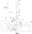
- FIG. 3 shows a wound sheet or web roll 82, that has reached its desired diameter, and which is in contact with a support drum 94.
- a reel spool 84 includes a shaft 86 which rests on support rail 92 which is secured by posts 88, 90. It is understood that each of the two ends of the spool is supported by a support rail.
- the reel spool 84 can also have a bearing housing (not shown) on each end that is in contact with the support rails.
- An RFID tag 80 which is secured to the spool 84, has an assigned identification spool number and/or spool tare weight.
- the identification numbers of the plurality of spools used in the papermaking plant and their associated tare weights can be stored in the database of control system 4 ( FIG. 1 ). In this fashion, once the identification number of a spool is known, its tare weight can be retrieved from the database.
- the RFID tag can be either passive, active or battery assisted passive. Active tags have batteries and transmits signals intermittently. Battery assisted passive tags are activated when it is activated by an RFID reader. Passive tags do not have batteries and use the radio energy transmitted by the reader for its energy source. Passive tags include an integrate circuit that is coupled with a transponder antenna for receiving interrogation signals from a RFID reader antenna and for transmitting a transponder signal. In this example, the tags used are passive. Reading or scanning spool tag 80 reveals this spool's unique identification number which in turn allows retrieval of its tare weigh from the database. Alternatively, the tare weight can be stored into the tag 80 so that reading the tag will reveal the tare weight.
- a lifting device 96 includes a cable 98 with a distal end 100, which is attachable to an overhead or bridge crane (not shown), and a proximal end which is secured to the top end of a strain gauge load cell 104 while a crane hook 106 is connected to its lower end.
- the load cell is operatively connected to a wireless transmitter 108.
- the load cell 104 is capable of sensing the weight of the roll 82 and the transmitter sends wireless signals that includes information representative of the weight.
- a pair of lifting devices each with a weight sensor and associated wireless transmitter are employed to raise the roll 82.
- the two load cells in the pair of lifting devices are calibrated so that their combined readings indicate the weight of the roll.
- the transmitter devices can be configured to operate under any known wireless communication protocols such as, for example, Wi-Fi and Bluetooth. Weight signals from the pair of transmitter devices are received by wireless receiver 40 ( FIG. 1 ).
- the RFID reader 110 in FIG. 3 has an antenna that is capable of transmitting the interrogation signal and receiving the RFID transponder signals from the spool tag 80 that are responsive to the interrogation signal.
- the spool tag transponder signal includes its identification number and/or tare weight.
- the RFID reader 110 is operatively connected to control system 4 ( FIG. 1 ) which processes the transponder signal from the spool RFID tag.
- the control system 4 receives weight signals from the pair of wireless transmitter devices. Based on this information, the computer in the control system calculates the actual gross weight of the sheet by subtracting the tare weight of the reel spool 84 from the weight of the roll 82. The computer also compares the actual gross weight to the estimated gross weight that was derived from the online measurements.
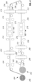
- FIG. 4 illustrates a process for coating a metal web or sheet that is used in fabricating electrodes for lithium-ion electrochemical cells and batteries.
- the electrode coating includes anodic active materials such as graphite and, for making cathodes, the electrode coating includes cathodic active materials such as a lithium metal oxide.
- Electrodes include a current collector metal foil that is coated on both sides of the foil with electrode slurry which can also include carbon black, binder, and solvent.
- a roll 200 is unwound by an unwinder and supplies a continuous metal web or sheet 230 that is coated on a top surface with a layer of electrode slurry by a coater 206.
- the basis weight, thickness, and other characteristics of the metal web or sheet 230 from roll 200 are usually known; scanning beta gauges 204 and 208 are employed to measure, respectively, the basis weight and/or thickness before, and after, the electrode slurry is applied by the coater 206.
- the coater 206 such as a tape casting coater, includes actuators that control a slot die/doctor blade to regulate the amount of slurry that is extruded onto the sheet 230.
- a dryer 210 removes excess solvents and cures the slurry that is on a moving coated sheet 232 to form an electrode layer on the sheet.
- Imaging devices 258 and 278 capture surface images of the coated sheet 232 before and after the dryer 210.
- a scanning beta gauge 212 measures the basis weight and/or thickness of the moving coated sheet 232 exiting the dryer 210 after the calender 254. Thereafter, rolling supports 234, 236 reverse the orientation of a moving sheet 238 so that the uncoated side is on top whereupon a coater 214 applies a layer of electrode slurry on the top uncoated surface of a moving sheet 238.
- the basis weight and/or thickness of a double-side coated sheet 240 are then measured with a scanning beta gauge 16 before entering a dryer 218.
- Imaging devices 270, 272, 274 and 276 are strategically located to capture top and bottom surface images.
- a beta gauge that is housed together with an infrared temperature sensor in a scanning device 224 measures the basis weight and/or thickness and the temperature of the double-coated sheet 242 as the scanning device 224 moves back and forth across the double-coated sheet 242. In particular the basis weight of each electrode layer is measured.
- a rewinder takes up the double-side coated sheet 242 into roll 244 which includes a reel spool 246 that is supported on rails (not shown). Surface defects on the top and bottom coatings are monitored by imaging devices 226, 228.
- the roll 244 is typically transferred to a calendering station whereby the double-coated electrode layer from the roll is unwound and passes through a calender which finishes and smooths the electrode layer.
- Reel spool 246 includes an RFID tag which can transmit an identification number and/or its tare weight. Before undergoing the calendering process, a pair of the lifting devices shown in FIG. 3 are used to obtain the weigh of the roll 244. The gross weight of roll 244 is determined by subtracting the tare weight of the reel spool 246 from the roll weight.
Landscapes
- Physics & Mathematics (AREA)
- General Physics & Mathematics (AREA)
- Engineering & Computer Science (AREA)
- Computer Networks & Wireless Communication (AREA)
- Theoretical Computer Science (AREA)
- Health & Medical Sciences (AREA)
- Toxicology (AREA)
- Mechanical Engineering (AREA)
- Computer Security & Cryptography (AREA)
- Electromagnetism (AREA)
- General Health & Medical Sciences (AREA)
- Artificial Intelligence (AREA)
- Computer Vision & Pattern Recognition (AREA)
- General Engineering & Computer Science (AREA)
- Paper (AREA)
- Arrangements For Transmission Of Measured Signals (AREA)
- Controlling Rewinding, Feeding, Winding, Or Abnormalities Of Webs (AREA)
Abstract
Description
- The present invention generally relates to quality control techniques for fabricating sheet materials and, more particularly, to systems for measuring the actual gross weight of a roll immediately after its production in a sheet making facility. The weight data allows dynamic verification of the accuracy of on-line basis weight measurements so that adjustments to the operating conditions of the sheetmaking process can be made.
- On-line measurements are used to detect properties of sheet materials during manufacture to enable prompt control of the sheetmaking processes and, thus, to assure sheet quality while reducing the quantity of substandard sheet material which is produced.
- In the manufacture of paper on continuous papermaking machines, a web of paper is formed from an aqueous suspension of fibers (stock) on a traveling mesh papermaking fabric and water drains by gravity and suction through the fabric. The web is then transferred to the pressing section where more water is removed by pressure and vacuum. The web next enters the dryer section where steam heated dryers and hot air completes the drying process. The paper machine is, in essence, a water removal system. A typical forming section of a papermaking machine includes an endless traveling papermaking fabric or wire, which travels over a series of water removal elements such as table rolls, foils, vacuum foils, and suction boxes. The stock is carried on the top surface of the papermaking fabric and is de-watered as the stock travels over the successive de-watering elements to form a sheet of paper. Finally, the wet sheet is transferred to the press section of the papermaking machine where enough water is removed to form a sheet of paper.
- It is well known to continuously measure certain properties of the paper material in order to monitor the quality of the finished product. These on-line measurements often include basis weight, moisture content, and sheet caliper, i.e., thickness. The measurements can be used for controlling process variables with the goal of maintaining output quality and minimizing the quantity of product that must be rejected due to disturbances in the manufacturing process. The on-line sheet property measurements are often accomplished by scanning sensors that periodically traverse the sheet material from edge to edge. It is conventional to measure the basis weight and/or caliper of sheet material after it leaves the main dryer section or at the take-up reel with scanning sensors. The basis weight of the sheet material produced is an important property however current production methods only provide online measurement estimates.
- The present invention is based, in part, on the development of a wireless technique of measuring the gross weight of the sheet material that is wound on the finished reel spool which generates real time weight readings to a control system. The actual weight measurements allow for fast dynamic correlations and verifications to the online estimate weight measurements. The operator can then adjust operating parameters of the various actuators and sensors in the papermaking process in response to measurement discrepancies.
- In one aspect, the invention is directed to a sheet production system that includes:
- a sheet of material which moves in a machine direction (MD);
- one or more actuators that are configured to form a liquid-containing sheet of material;
- means for drying the liquid-containing sheet of material to form a sheet of dried material;
- means for calculating the basis weight of the sheet of dried material;
- means for reeling a traveling sheet of dried material that is produced to form a roll of material; and
- means for weighing the roll of material. Preferred devices for weighing the roll include load cells which refers to any type of sensor useful for measuring force, such as, for example, force sensors, force transducers, and the like.
- In another aspect, the invention is directed to a method of operating a sheetmaking system that produces a continuous sheet that travels in the MD which includes:
- (a) forming a sheet of material that contains a liquid;
- (b) determining the basis weight of the sheet of material;
- (c) reeling the traveling sheet of material into a roll;
- (d) calculating the weight of the sheet material in the roll using basis weights determined in step (b) to yield an estimate weight; and
- (e) weighing the roll to determine the actual weight of the sheet of material in the roll.
- In a further aspect, the invention is directed to an apparatus for determining the gross weight of sheet material on a roll that includes:
- a spool that is equipped with a radio frequency identification (RFID) tag to identify its tare weight and/or its spool identification number wherein the spool is configured to wind the sheet of material;
- means for lifting a roll of material that is wound on the spool and comprises a sensor configured to sense a force produced by the roll of material when lifted and transmitting wireless signals that include information representative of the force produced by the roll of material; and
- means for calculating the gross weight of the sheet of material wound on the roll.
- In one embodiment, the apparatus includes a pair of lifting devices each equipped with a load cell which is connected to a Wi-Fi signal transmitter or a Bluetooth signal transmitter.
- While the invention will be illustrated as being implemented in papermaking, it is understood that the invention is applicable in other continuous sheet making processes such as, for example, in the manufacturer of rubber sheets, plastic films, lithium-ion battery electrodes, fabrics and the like.
-
-
FIG. 1 is a schematic illustration of a papermaking system; -
FIG. 2 is a scanning sensor; -
FIG. 3 is a side view of a lift mechanism for weighing a roll; and -
FIG. 4 is a schematic illustration of a lithium-ion battery electrode manufacturing system. -
FIG. 1 illustrates asheetmaking system 10 that includespapermaking machine 2,control system 4 andnetwork 6. Thepapermaking machine 2 produces a continuous sheet ofpaper material 12, which can be more than 10 meters in width, that is collected in take-up reel 14. Thepaper material 12, having a specific width, is produced from a pulp suspension feedstock, comprising of an aqueous mixture of wood fibers and other materials, which undergoes various unit operations that are monitored and controlled by aquality control system 4. Thenetwork 6 facilitates communication between the components ofsystem 10. - The
papermaking machine 2 includes a headbox 8, which distributes an aqueous pulp suspension uniformly across the machine onto a continuous screen orwire 30 that is moving in the machine direction (MD). Headbox 8 includes slice openings through which the pulp suspension is distributed onto screen orwire 30 which comprise a suitable structure such as a mesh for receiving a pulp suspension and allowing water or other materials to drain or leave the pulp suspension. The formation of thepaper sheet 12 is influenced by a plurality oflinear actuators 3 extending in the cross direction across thesheet 12 of paper being formed.Actuators 3 control the sheet's weight in the cross direction (CD). Sensors located downstream from the actuators measure the properties of the sheet. The feedstock is fed from the head box through a gap orelongated orifice 5 onto awire section 30. The orifice or gap is a relatively narrow opening that extends across the width of the machine. Weight profile control in such an arrangement is achieved by locally adjusting the position of the slice lip across the machine with motorizedlinear actuators 3 to vary the dimensions of the gap or orifice immediately adjacent the actuator. As used herein, the "wet end" forming portion ofsheetmaking system 10 comprises headbox 8 andwire 30 and those sections before thewire 30, and the "dry end" comprises the sections that are downstream fromwire 30. -
Sheet 12 then enters apress section 32, which includes multiple press rolls wheresheet 12 travels through the openings (referred to as "nips") between pairs of counter-rotating rolls inpress section 32. In this way, the rolls inpress section 32 compress the pulpmaterial forming sheet 12. This may help to remove more water from the pulp material and to equalize the characteristics of thesheet 12 on both of its sides. Atachometer 38 measures the MD line speed. - As
sheet 12 travels over a series of heated rolls indryer section 34, more water insheet 12 is evaporated. Acalendar 36 processes and finishessheet 12, for example, by smoothing and imparting a final finish, thickness, gloss, or other characteristic tosheet 12. Other materials (such as starch or wax) can also be added tosheet 12 to obtain the desired finish. An array ofinduction heating actuators 24 applies heat along the CD to one or more of the rollers to control the roll diameters and thereby the size of the nips. Once processing bycalendar 36 is complete,sheet 12 is collected ontoreel 14. A Wi-Fi or Bluetooth receiver is positioned in the vicinity ofreel 14. -
Sheetmaking system 10 further includes an array ofsteam actuators 20 that controls the amount of hot steam that is projected along the CD. The hot steam increases the paper surface temperature and allows for easier cross direction removal of water from the paper sheet. Also, to reduce or prevent over drying of the paper sheet,paper material 14 is sprayed with water in the CD. Similarly, an array ofrewet shower actuators 22 controls the amount of water that is applied along the CD. - In order to control the papermaking process, selected properties of
sheet 12 are continuously measured and thepapermaking machine 2 adjusted to ensure sheet quality. Typical physical characteristics of paper that are can be measured include, for example, thickness, basis weight, moisture content, chemical composition such as ash, surface roughness, gloss, caliper, color, and crepe pattern surface features. CD control may be achieved by measuring sheet properties using one ormore scanners sheet 12 and measuring one or more characteristics ofsheet 12. For example,scanner 28 could carry sensors for measuring the dry weight, moisture content, ash content, or any other or additional characteristics ofsheet 12.Scanner 28 includes suitable structures for measuring or detecting one or more characteristics ofsheet 12, such as a set or array of sensors.Scanner 28 is particularly suited for measuring the dry end dry weight and caliper of the paper product at the take-up reel 14. Suitable caliper scanning sensors, are described inU.S. Pat. No. 6,967,726 to King et al. andU.S. Pat. No. 4,678,915 to Dahlquist et al. , which are incorporated herein by reference. - Measurements from
scanners system 4 that adjusts various actuators or operations ofpapermaking machine 2 that affect machine direction and cross direction characteristics ofsheet 12. A machine direction characteristic ofsheet 12 generally refers to an average characteristic ofsheet 12 that varies and is controlled in the machine direction. In this example,control system 4 is capable of controlling the dry weight of the paper sheet by adjusting the supply of pulp to the headbox 8. For example,control system 4 could provide information to a stock flow controller that regulates the flow of stock through valves and to headbox 8.Control system 4 includes any hardware, software, firmware, or combination thereof for controlling the operation of thesheetmaking machine 2 or other machine.Control system 4 includes computer with a processor and memory storing instructions and data used, generated, and collected by the processor. -
FIG. 2 illustrates one particular implementation of the scanning sensor which is located at the dry end just before the take-up reel ofFIG. 1 . In particular, the radiation source and detector are housed in a dualmounting head scanner 58 ofscanner system 50 which can be employed to measure one or more characteristics of the paper that is produced.Upper scanner head 54 moves repeatedly back and forth in the CD across the width of the movingsheet 60, which moves in the MD, so that the characteristics of the entire sheet may be measured.Scanner 58 or gauge is supported by twotransverse beams sheet 60. Thelower scanner head 56 may include a sheet stabilization system such as an air-bearing stabilizer (not shown) to maintain the sheet on a consistent plane as it passes through the measurement window. The movement of the dual scanner heads 54, 56, is synchronized with respect to speed and direction so that they are aligned with each other. The scanners are also equipped with edge detectors (not shown) that measure sheet width. - Depending on the properties being monitored, the scanning sensors can be configured to operate in the transmissive mode or reflective mode. Basis weight scanning sensors are described, for example, in
U.S. Pat. No. 10,935,368 to Tixier U.S. 2015/0022220 to Tixier and Hughes , which are incorporated herein by reference. For instance,scanner head 54 can house a radiation source that directs a beam of radiation into a moving web orsheet 26 andscanner head 56 houses a radiation receiver that detects radiation that is transmitted through the material. As the dual scanner heads advances back and forth along the CD, the sensor measures one or more properties of the web orsheet 60. In the reflective mode, theupper scanner head 54 can house both a radiation source and detector to measure one or more characteristics of the web orsheet 26. - During paper production, the basis weight, caliper, sheet width and machine direction speed of the moving sheet of paper are continuously monitored. The accumulated data allows the weight of the paper that is wound onto a spool of a finished roll to be estimated.
-
FIG. 3 shows a wound sheet orweb roll 82, that has reached its desired diameter, and which is in contact with asupport drum 94. Areel spool 84 includes a shaft 86 which rests onsupport rail 92 which is secured byposts reel spool 84 can also have a bearing housing (not shown) on each end that is in contact with the support rails. AnRFID tag 80, which is secured to thespool 84, has an assigned identification spool number and/or spool tare weight. The identification numbers of the plurality of spools used in the papermaking plant and their associated tare weights can be stored in the database of control system 4 (FIG. 1 ). In this fashion, once the identification number of a spool is known, its tare weight can be retrieved from the database. - The RFID tag can be either passive, active or battery assisted passive. Active tags have batteries and transmits signals intermittently. Battery assisted passive tags are activated when it is activated by an RFID reader. Passive tags do not have batteries and use the radio energy transmitted by the reader for its energy source. Passive tags include an integrate circuit that is coupled with a transponder antenna for receiving interrogation signals from a RFID reader antenna and for transmitting a transponder signal. In this example, the tags used are passive. Reading or
scanning spool tag 80 reveals this spool's unique identification number which in turn allows retrieval of its tare weigh from the database. Alternatively, the tare weight can be stored into thetag 80 so that reading the tag will reveal the tare weight. - A lifting
device 96 includes acable 98 with adistal end 100, which is attachable to an overhead or bridge crane (not shown), and a proximal end which is secured to the top end of a straingauge load cell 104 while acrane hook 106 is connected to its lower end. The load cell is operatively connected to awireless transmitter 108. - The
load cell 104 is capable of sensing the weight of theroll 82 and the transmitter sends wireless signals that includes information representative of the weight. In operation, a pair of lifting devices each with a weight sensor and associated wireless transmitter are employed to raise theroll 82. The two load cells in the pair of lifting devices are calibrated so that their combined readings indicate the weight of the roll. The transmitter devices can be configured to operate under any known wireless communication protocols such as, for example, Wi-Fi and Bluetooth. Weight signals from the pair of transmitter devices are received by wireless receiver 40 (FIG. 1 ). - The
RFID reader 110 inFIG. 3 has an antenna that is capable of transmitting the interrogation signal and receiving the RFID transponder signals from thespool tag 80 that are responsive to the interrogation signal. The spool tag transponder signal includes its identification number and/or tare weight. TheRFID reader 110 is operatively connected to control system 4 (FIG. 1 ) which processes the transponder signal from the spool RFID tag. In addition, thecontrol system 4 receives weight signals from the pair of wireless transmitter devices. Based on this information, the computer in the control system calculates the actual gross weight of the sheet by subtracting the tare weight of thereel spool 84 from the weight of theroll 82. The computer also compares the actual gross weight to the estimated gross weight that was derived from the online measurements. - The present invention can be applied to other sheet making processes that produce liquid containing materials that are wound into a roll such as in the production of lithium-ion electrodes.
FIG. 4 illustrates a process for coating a metal web or sheet that is used in fabricating electrodes for lithium-ion electrochemical cells and batteries. For making anodes, the electrode coating includes anodic active materials such as graphite and, for making cathodes, the electrode coating includes cathodic active materials such as a lithium metal oxide. Electrodes include a current collector metal foil that is coated on both sides of the foil with electrode slurry which can also include carbon black, binder, and solvent. After the electrode slurry is applied on a side of foil, the wet coated foil is heated in a dryer to extract the solvent to leave a solid layer of electrode material which adheres to the metal foil. Copper foil is a preferred anode current collector material and aluminum foil is a preferred cathode current collector material. As shown inFIG. 4 , a roll 200 is unwound by an unwinder and supplies a continuous metal web or sheet 230 that is coated on a top surface with a layer of electrode slurry by acoater 206. The basis weight, thickness, and other characteristics of the metal web or sheet 230 from roll 200 are usually known; scanning beta gauges 204 and 208 are employed to measure, respectively, the basis weight and/or thickness before, and after, the electrode slurry is applied by thecoater 206. - The
coater 206, such as a tape casting coater, includes actuators that control a slot die/doctor blade to regulate the amount of slurry that is extruded onto the sheet 230. Adryer 210 removes excess solvents and cures the slurry that is on a movingcoated sheet 232 to form an electrode layer on the sheet.Imaging devices coated sheet 232 before and after thedryer 210. - A
scanning beta gauge 212 measures the basis weight and/or thickness of the movingcoated sheet 232 exiting thedryer 210 after the calender 254. Thereafter, rollingsupports sheet 238 so that the uncoated side is on top whereupon acoater 214 applies a layer of electrode slurry on the top uncoated surface of a movingsheet 238. The basis weight and/or thickness of a double-sidecoated sheet 240 are then measured with a scanning beta gauge 16 before entering adryer 218.Imaging devices - Further downstream, a beta gauge that is housed together with an infrared temperature sensor in a
scanning device 224 measures the basis weight and/or thickness and the temperature of the double-coated sheet 242 as thescanning device 224 moves back and forth across the double-coated sheet 242. In particular the basis weight of each electrode layer is measured. A rewinder takes up the double-sidecoated sheet 242 intoroll 244 which includes areel spool 246 that is supported on rails (not shown). Surface defects on the top and bottom coatings are monitored by imagingdevices roll 244 is typically transferred to a calendering station whereby the double-coated electrode layer from the roll is unwound and passes through a calender which finishes and smooths the electrode layer. -
Reel spool 246 includes an RFID tag which can transmit an identification number and/or its tare weight. Before undergoing the calendering process, a pair of the lifting devices shown inFIG. 3 are used to obtain the weigh of theroll 244. The gross weight ofroll 244 is determined by subtracting the tare weight of thereel spool 246 from the roll weight. - The foregoing has described the principles, preferred embodiments and modes of operation of the present invention. However, the invention should not be construed as being limited to the particular embodiments discussed. Thus, the above-described embodiments should be regarded as illustrative rather than restrictive, and it should be appreciated that variations may be made in those embodiments by workers skilled in the art without departing from the scope of the present invention as defined by the following claims.
Claims (15)
- A sheet production system that comprises:a sheet of material which moves in a machine direction;one or more actuators that are configured to form a liquid-containing sheet of material;means for drying the liquid-containing sheet of material to form a sheet of dried material;means for calculating the basis weight of the sheet of dried material;means for reeling a traveling sheet of dried material that is produced to form a roll of material; andmeans for weighing the roll of material.
- The system of claim 1 wherein the means for reeling the traveling sheet of dried material comprises a spool onto which the traveling sheet of dried material is wound and the spool has a radio frequency identification tag for identifying the spool and/or the weight of the spool.
- The system of claim 2 comprising a computer that includes a database that contains weight information for a plurality of spools associated with the sheet production system.
- The system of claim 1 wherein the means for weighing of the roll of material is configured to lift the roll of material and comprises a sensor configured to sense a force produced by the roll of material when lifted and to transmit wireless signals that include information representative of the force produced by the roll of material.
- The system of claim 4 wherein the sensor is operatively connected to a Wi-Fi transmitter or Bluetooth transmitter.
- A method of operating a sheet making system that produces a continuous sheet that travels in the machine direction which comprises:(a) forming a sheet of material that contains a liquid;(b) determining the basis weight of the sheet of material;(c) reeling the traveling sheet of material into a roll;(d) calculating the weight of the sheet material in the roll using basis weights determined in step (b) to yield an estimate weight; and(e) weighing the roll to determine the actual weight of the sheet of material in the roll.
- The method of claim 6 wherein in step (c) the traveling sheet is wound on a spool and step (e) comprises lifting the roll of material and weighing the roll of material with a sensor that transmits wireless signals which include information representative of the weight of the roll and thereafter subtracting the weight of the spool from the weight of the roll.
- The method of claim 7 wherein the spool has a radio frequency identification tag that sends signals that identifies the spool and/or the weight of the spool.
- The method of claim 7 comprises establishing a database that contains weight information for a plurality of spools associated with the sheet making system.
- The method of claim 6 comprises comparing the actual weight to the estimate weight and adjusting one or more actuators used in forming the sheet of material that contains a liquid.
- An apparatus for determining the gross weight of sheet material on a roll that comprises:a spool that is equipped with a radio frequency identification (RFID) tag to identify its tare weight and/or its spool identification number wherein the spool is configured to wind the sheet of material;means for lifting a roll of material that is wound on the spool and comprises a sensor configured to sense a force produced by the roll of material when lifted and transmitting wireless signals that include information representative of the force produced by the roll of material; andmeans for calculating the gross weight of the sheet of material wound on the roll.
- The apparatus of claim 11 wherein the sensor is operatively connected to a Wi-Fi transmitter or Bluetooth transmitter.
- The apparatus of claim 11 wherein the sensor comprises a load cell arranged to detect a force generated by the weight of the roll when lifted.
- The apparatus of claim 11 wherein the means for calculating the gross weight comprises a computer which receives the wireless signals and RFID signals from the tag.
- The apparatus of claim 14 wherein the computer includes a database that contains weight information for a plurality of spools associated with a sheet production system.
Applications Claiming Priority (1)
| Application Number | Priority Date | Filing Date | Title |
|---|---|---|---|
| US18/221,156 US20250020502A1 (en) | 2023-07-12 | 2023-07-12 | Roll Weight System for On Machine Dynamic Verification |
Publications (2)
| Publication Number | Publication Date |
|---|---|
| EP4491794A2 true EP4491794A2 (en) | 2025-01-15 |
| EP4491794A3 EP4491794A3 (en) | 2025-07-09 |
Family
ID=91617236
Family Applications (1)
| Application Number | Title | Priority Date | Filing Date |
|---|---|---|---|
| EP24183001.7A Pending EP4491794A3 (en) | 2023-07-12 | 2024-06-19 | Roll weight system for on machine dynamic verification |
Country Status (6)
| Country | Link |
|---|---|
| US (1) | US20250020502A1 (en) |
| EP (1) | EP4491794A3 (en) |
| JP (1) | JP2025013221A (en) |
| KR (1) | KR20250010546A (en) |
| CN (1) | CN119309662A (en) |
| CA (1) | CA3245037A1 (en) |
Citations (4)
| Publication number | Priority date | Publication date | Assignee | Title |
|---|---|---|---|---|
| US4678915A (en) | 1982-05-17 | 1987-07-07 | Measurex Corporation | System and process for measuring and correcting the values of a parameter of a sheet material |
| US6967726B2 (en) | 2003-10-03 | 2005-11-22 | Honeywell International Inc. | Means for in-place automated calibration of optically-based thickness sensor |
| US20150022220A1 (en) | 2013-07-22 | 2015-01-22 | Honeywell Asca Inc. | Multi-frequency Microwave Sensor for Temperature Independent Measurement of Moisture |
| US10935368B2 (en) | 2018-03-14 | 2021-03-02 | Honeywell Limited | Scanning caliper and basis weight sensor for sheet products using terahertz |
Family Cites Families (10)
| Publication number | Priority date | Publication date | Assignee | Title |
|---|---|---|---|---|
| US4879471A (en) * | 1987-03-25 | 1989-11-07 | Measurex Corporation | Rapid-scanning infrared sensor |
| JPH03199924A (en) * | 1989-12-27 | 1991-08-30 | Dai Showa Seishi Kk | Method and apparatus for measuring roll-shaped material |
| US6089498A (en) * | 1998-06-26 | 2000-07-18 | Sticht; Walter | Monitoring means for an end of a thread-like material wound on a supply coil and process for this |
| JP2002370872A (en) * | 2001-06-13 | 2002-12-24 | Mitsubishi Heavy Ind Ltd | Reel spool identification device and papermaking equipment |
| US7459060B2 (en) * | 2005-08-22 | 2008-12-02 | Honeywell Asca Inc. | Reverse bump test for closed-loop identification of CD controller alignment |
| US10501274B2 (en) * | 2017-07-06 | 2019-12-10 | Honeywell International Inc. | Continuous web sheet defect analytics, classification and remediation for enhancing equipment efficiency and throughput |
| IT201800006680A1 (en) * | 2018-06-26 | 2019-12-26 | METHOD FOR PREDICTING THE PRESENCE OF PRODUCT DEFECTS DURING AN INTERMEDIATE PROCESSING PHASE OF A THIN PRODUCT WRAPPED IN COIL | |
| CN108584703B (en) * | 2018-07-18 | 2019-07-02 | 安徽工业大学 | On-line measuring system and measuring method of lifting weight and deflection of main girder of double-girder bridge crane |
| US20220258271A1 (en) * | 2021-02-17 | 2022-08-18 | Illinois Tool Works Inc. | Multiple Position Wire Feed Spool Delivery System |
| EP4313816B1 (en) * | 2021-03-30 | 2025-12-17 | Kimberly-Clark Worldwide, Inc. | System and method for building a roll of material |
-
2023
- 2023-07-12 US US18/221,156 patent/US20250020502A1/en active Pending
-
2024
- 2024-06-11 CN CN202410742629.7A patent/CN119309662A/en active Pending
- 2024-06-19 EP EP24183001.7A patent/EP4491794A3/en active Pending
- 2024-07-01 JP JP2024105933A patent/JP2025013221A/en active Pending
- 2024-07-02 CA CA3245037A patent/CA3245037A1/en active Pending
- 2024-07-05 KR KR1020240088941A patent/KR20250010546A/en active Pending
Patent Citations (5)
| Publication number | Priority date | Publication date | Assignee | Title |
|---|---|---|---|---|
| US4678915A (en) | 1982-05-17 | 1987-07-07 | Measurex Corporation | System and process for measuring and correcting the values of a parameter of a sheet material |
| US4678915B1 (en) | 1982-05-17 | 1996-07-16 | Measurex Corp | System and process for measuring and correcting the values of a parameter of a sheet material |
| US6967726B2 (en) | 2003-10-03 | 2005-11-22 | Honeywell International Inc. | Means for in-place automated calibration of optically-based thickness sensor |
| US20150022220A1 (en) | 2013-07-22 | 2015-01-22 | Honeywell Asca Inc. | Multi-frequency Microwave Sensor for Temperature Independent Measurement of Moisture |
| US10935368B2 (en) | 2018-03-14 | 2021-03-02 | Honeywell Limited | Scanning caliper and basis weight sensor for sheet products using terahertz |
Also Published As
| Publication number | Publication date |
|---|---|
| JP2025013221A (en) | 2025-01-24 |
| EP4491794A3 (en) | 2025-07-09 |
| CN119309662A (en) | 2025-01-14 |
| KR20250010546A (en) | 2025-01-21 |
| US20250020502A1 (en) | 2025-01-16 |
| CA3245037A1 (en) | 2025-06-06 |
Similar Documents
| Publication | Publication Date | Title |
|---|---|---|
| US12597593B2 (en) | Manufacturing method for traceability of battery electrodes with fiducial markers | |
| CA2327792C (en) | Water weight sensor array imbedded in a sheetmaking machine roll | |
| US7780817B2 (en) | Measurement system for improved paper roll runnability | |
| WO1998026282A1 (en) | Electromagnetic field perturbation sensor and methods for measuring water content in sheetmaking systems | |
| US7799171B2 (en) | Reeling method and system as well as an measuring apparatus | |
| US20250020502A1 (en) | Roll Weight System for On Machine Dynamic Verification | |
| EP4481519A1 (en) | Automated interframe alignment monitoring for sheet manufacturing applications | |
| EP1342839B1 (en) | Method and apparatus for measuring the hardness or compactness of a clothing | |
| EP1342843B1 (en) | Method and system for controlling the web formation | |
| EP4313816B1 (en) | System and method for building a roll of material | |
| US20240384469A1 (en) | Mini-Scan for Dynamic Correlation | |
| CN121089637B (en) | Coating equipment and pole piece coating thickness detection method | |
| Parent et al. | A guide to eliminating baggy webs | |
| Linna et al. | Variation of the web tension at the roll change in the printing press | |
| CN121089637A (en) | Coating equipment and pole piece coating thickness detection method | |
| FI117343B (en) | A method and system for preventing vibration | |
| FI121113B (en) | Rolling method and system | |
| JP2003211072A (en) | Coating profile control method |
Legal Events
| Date | Code | Title | Description |
|---|---|---|---|
| PUAI | Public reference made under article 153(3) epc to a published international application that has entered the european phase |
Free format text: ORIGINAL CODE: 0009012 |
|
| STAA | Information on the status of an ep patent application or granted ep patent |
Free format text: STATUS: REQUEST FOR EXAMINATION WAS MADE |
|
| 17P | Request for examination filed |
Effective date: 20240619 |
|
| AK | Designated contracting states |
Kind code of ref document: A2 Designated state(s): AL AT BE BG CH CY CZ DE DK EE ES FI FR GB GR HR HU IE IS IT LI LT LU LV MC ME MK MT NL NO PL PT RO RS SE SI SK SM TR |
|
| PUAL | Search report despatched |
Free format text: ORIGINAL CODE: 0009013 |
|
| AK | Designated contracting states |
Kind code of ref document: A3 Designated state(s): AL AT BE BG CH CY CZ DE DK EE ES FI FR GB GR HR HU IE IS IT LI LT LU LV MC ME MK MT NL NO PL PT RO RS SE SI SK SM TR |
|
| RIC1 | Information provided on ipc code assigned before grant |
Ipc: B65H 20/02 20060101ALI20250530BHEP Ipc: B65H 18/08 20060101ALI20250530BHEP Ipc: B65H 18/00 20060101ALI20250530BHEP Ipc: D21G 9/00 20060101ALI20250530BHEP Ipc: D21F 7/00 20060101AFI20250530BHEP |