EP4491792A1 - Condenser and laundry treatment device - Google Patents
Condenser and laundry treatment device Download PDFInfo
- Publication number
- EP4491792A1 EP4491792A1 EP23773815.8A EP23773815A EP4491792A1 EP 4491792 A1 EP4491792 A1 EP 4491792A1 EP 23773815 A EP23773815 A EP 23773815A EP 4491792 A1 EP4491792 A1 EP 4491792A1
- Authority
- EP
- European Patent Office
- Prior art keywords
- flow guiding
- condenser
- guiding plate
- airflow
- condensate
- Prior art date
- Legal status (The legal status is an assumption and is not a legal conclusion. Google has not performed a legal analysis and makes no representation as to the accuracy of the status listed.)
- Pending
Links
Images






Classifications
-
- D—TEXTILES; PAPER
- D06—TREATMENT OF TEXTILES OR THE LIKE; LAUNDERING; FLEXIBLE MATERIALS NOT OTHERWISE PROVIDED FOR
- D06F—LAUNDERING, DRYING, IRONING, PRESSING OR FOLDING TEXTILE ARTICLES
- D06F58/00—Domestic laundry dryers
- D06F58/20—General details of domestic laundry dryers
- D06F58/24—Condensing arrangements
-
- D—TEXTILES; PAPER
- D06—TREATMENT OF TEXTILES OR THE LIKE; LAUNDERING; FLEXIBLE MATERIALS NOT OTHERWISE PROVIDED FOR
- D06F—LAUNDERING, DRYING, IRONING, PRESSING OR FOLDING TEXTILE ARTICLES
- D06F39/00—Details of washing machines not specific to a single type of machines covered by groups D06F9/00 - D06F27/00
- D06F39/10—Filtering arrangements
-
- D—TEXTILES; PAPER
- D06—TREATMENT OF TEXTILES OR THE LIKE; LAUNDERING; FLEXIBLE MATERIALS NOT OTHERWISE PROVIDED FOR
- D06F—LAUNDERING, DRYING, IRONING, PRESSING OR FOLDING TEXTILE ARTICLES
- D06F58/00—Domestic laundry dryers
- D06F58/20—General details of domestic laundry dryers
- D06F58/22—Lint collecting arrangements
-
- D—TEXTILES; PAPER
- D06—TREATMENT OF TEXTILES OR THE LIKE; LAUNDERING; FLEXIBLE MATERIALS NOT OTHERWISE PROVIDED FOR
- D06F—LAUNDERING, DRYING, IRONING, PRESSING OR FOLDING TEXTILE ARTICLES
- D06F25/00—Washing machines with receptacles, e.g. perforated, having a rotary movement, e.g. oscillatory movement, the receptacle serving both for washing and for centrifugally separating water from the laundry and having further drying means, e.g. using hot air
Definitions
- the application relates to the technical field of laundry washing and care, and in particular to a condensation device and a laundry treatment device.
- drying processes thereof usually require usage of a condenser to reduce humidity of humid and hot airflow.
- Operation principles of the condenser are as follows. After the humid and hot airflow discharged from the drum enters the condenser, it comes into contact with condensate water in the condenser. During contact, vapor in the humid and hot airflow is condensed into water, and the condensed water is mixed into the condensate water and discharged through a water outlet pipe. The humid and hot airflow after condensation becomes relatively dry cold air in turn, and enters the drum again.
- the condenser usually requires a large condensate drop and a large airflow flowing distance. Therefore, the condenser has a large volume and many structural limitations.
- embodiments of the application are desired to provide a condenser and a laundry treatment device with relatively compact structures.
- an embodiment of the application provides a condenser, the condenser comprises a condensation pipe.
- the condensation pipe is provided with an air inlet, an air outlet, a water inlet and a water outlet, an airflow channel extending in a transverse direction is formed between the air inlet and the air outlet, the water inlet is located at an upper side of the airflow channel, the water outlet is located at a lower side of the airflow channel, a condensate flowing path passing through the airflow channel is formed between the water inlet and the water outlet.
- a height of a highest point of the air inlet may be equal to or higher than a height of a lowest point of the air outlet.
- a height of a highest point of the water inlet is equal to or higher than the height of the lowest point of the air outlet.
- the condensation pipe may be provided with a partition wall therein, the airflow channel and a water outlet channel located at the lower side of the airflow channel is separated by the partition wall in the condensation pipe, and the water outlet channel is provided with the water outlet.
- the partition wall is provided thereon with a water-passage opening connecting the airflow channel and the water outlet channel; or, a part of edges of the partition wall is spaced from an inner wall of the condensation pipe to form at the spacing the water-passage opening connecting the airflow channel and the water outlet channel.
- an area where the condensate flowing path passes through the airflow channel may be located downstream of the water-passage opening in an airflow flowing direction, a part of an area at a side of the partition wall facing the airflow channel forms a flow guiding surface, and the flow guiding surface guides the condensate flowing path to extend toward the water-passage opening.
- the airflow channel may be provided with a first extension section and a second extension section.
- the second extension section is communicated with the first extension section and extends toward a side of the first extension section, an end of the first extension section away from the second extension section is provided with the air inlet, an end of the second extension section away from the first extension section is provided with the air outlet, and the condensate flowing path passes through the first extension section.
- the condenser may further comprise a flow guiding assembly arranged in the airflow channel, and the flow guiding assembly is located on the condensate flowing path to guide flow of condensate flowing along the condensate flowing path.
- the flow guiding assembly may comprise a flow guiding plate, the flow guiding plate guides the condensate to flow toward at least one of two opposite sides of the flow guiding plate in an airflow flowing direction.
- the flow guiding plate may be provided with a flow collection groove thereon.
- the flow guiding assembly may comprise multiple flow guiding plates, and the flow guiding plates are arranged at intervals.
- each of the flow guiding plates may be arranged in a layer in a vertical direction.
- a part of multiple flow guiding plates may be arranged in respective layers in the vertical direction, and a part of multiple flow guiding plates are arranged at respective intervals in the transverse direction.
- relative positions of at least some adjacent flow guiding plates in the vertical direction from multiple flow guiding plates may satisfy that along a condensate flowing direction, the flow guiding plate located downstream may receive at least a part of condensate flowing down from the flow guiding plate located upstream.
- An embodiment of the application further provides a laundry treatment device, the laundry treatment device comprises a barrel assembly, the condenser as described above, a filtering device, and an air guiding device.
- the barrel assembly is provided with a laundry treatment cavity, and with an air-in opening and an air-out opening communicating with the laundry treatment cavity respectively.
- the condenser is arranged at top of the barrel assembly.
- the filtering device is connected with the air-out opening and the air inlet.
- the air guiding device is connected with the air outlet and the air-in opening.
- the airflow channel may be arranged in a left-right direction of the barrel assembly.
- the water outlet may be located at a rear side of the barrel assembly in an axial direction.
- the airflow channel extends in the transverse direction
- the water inlet is located at the upper side of the airflow channel
- the water outlet is located at the lower side of the airflow channel
- the condensate flowing path formed between the water inlet and the water outlet passes through the airflow channel from top to bottom
- the condensate flowing along the condensate flowing path flows downward with an action of its own gravity, and exchanges heat with the humid and hot airflow flowing along the airflow channel when it passes through the airflow channel.
- the condenser does not require a large airflow flowing distance in the vertical direction, nor does it require a large condensate drop. That is, the condenser is not affected by the condensate drop and the airflow flowing distance, structures thereof are not only relatively compact, but also are flexible and variable, which may adapt to more functional structures, especially some special filtering devices.
- orientation or position relationships such as “left” and “right” are based on orientation or position relationships shown in FIG. 1
- orientation or position relationships such as “transverse direction”, “up” and “down” are based on orientation or position relationships shown in FIG. 4
- vertical direction is an up-down direction in FIG. 4 .
- the condenser 10 comprises a condensation pipe 11.
- the condensation pipe 11 is provided with an air inlet 11a, an air outlet 11b, a water inlet 11c, and a water outlet 11d therein.
- An airflow channel 11e extending in a transverse direction is formed between the air inlet 11a and the air outlet 11b. That is, the air inlet 11a and the air outlet 11b are located at two opposite sides of the condensation pipe 11 in the transverse direction respectively. Airflow flowing from the air inlet 11a into the condensation pipe 11 may flow along the airflow channel 11e in the transverse direction, and flow out from the air outlet 11b. That is, a path in the airflow channel 11e is an airflow flowing path. It should be noted that the airflow channel 11e described here only needs to extend in the transverse direction, and is not limited to flowing from a specified side to another specified side necessarily.
- the water inlet 11c is located at an upper side of the airflow channel 11e, the water outlet 11d is located at a lower side of the airflow channel 11e. That is, an arrangement height of the water inlet 11c is higher than an arrangement height of the airflow channel 11e, and an arrangement height of the water outlet 11d is lower than the arrangement height of the airflow channel 11e.
- a condensate flowing path passing through the airflow channel 11e is formed between the water inlet 11c and the water outlet 11d.
- the water inlet 11c of the condensation pipe 11 is located at an upper side of the water outlet 11d, the condensate flowing path formed between the water inlet 11c and the water outlet 11d extends from top to bottom, the condensate flowing from the water inlet 11c into the condensation pipe 11 falls from the upper side of the airflow channel 11e with an action of its own gravity, and passes through the airflow channel 11e during falling, and flows out from the water outlet 11d finally.
- compositions of the condensate are not limited, and may be water or other types of liquids.
- the condenser 10 is configured to dehumidify and cool down humid and hot airflow. Specifically, the humid and hot airflow enters the condensation pipe 11 from the air inlet 11a and flows along the airflow channel 11e, and the condensate enters the condensation pipe 11 from the water inlet 11c and flows along the condensate flowing path; when the humid and hot airflow passes through the condensate, the humid and hot airflow exchanges heat with the condensate, the condensate absorbs heat of the humid and hot airflow, vapor in the humid and hot airflow is precipitated from the airflow due to cooling down and is condensed into droplets, the droplets are mixed into the condensate and discharged from the water outlet finally.
- the low-temperature dry airflow is defined relative to the humid and hot airflow, and temperature of the low-temperature dry airflow is lower than temperature of the humid and hot airflow.
- the low temperature in the embodiment of the application may be room temperature.
- the condenser 10 in the embodiment of the application may be used in any appropriate scenario.
- the embodiment of the application is described by taking the condenser 10 applied to a laundry treatment device as an example.
- an embodiment of the application provides a laundry treatment device
- the laundry treatment device comprises a barrel assembly 20, a filtering device 30, an air guiding device 40, and the condenser 10 in any one of the embodiments of the application.
- the condenser 10 is arranged at top of the barrel assembly 20.
- the barrel assembly 20 is provided with a laundry treatment cavity, and an air-in opening and an air-out opening communicated with the laundry treatment cavity.
- the filtering device 30 is communicated with the air-out opening and the air inlet 11a.
- the air guiding device 40 is communicated with the air outlet 11b and the air-in opening. It should be noted that the air guiding device 40 is equipped with a fan and a heater therein.
- the airflow channel 11e of the condenser 10 shown in FIG. 1 is arranged in a left-right direction of the barrel assembly 20. That is, a large part of areas of the airflow channel 11e extends along left and right sides of the barrel assembly 20.
- the airflow channel 11e of the condenser 10 may also be arranged in an axial direction of the barrel assembly 20.
- the water outlet 11d of the condenser 10 shown in FIG. 1 is located at a rear side of the barrel assembly 20 in an axial direction. That is, a part of structures of the condenser 10 may extend to the rear side of the barrel assembly 20 in the axial direction, to facilitate water outlet.
- An airflow circulation channel is formed in the laundry treatment device, and the air guiding device 40 guides a dry hot airflow into the laundry treatment cavity through the air-in opening.
- the dry hot airflow flows through surfaces of wet laundries, exchanges heat and moisture with the wet laundries, absorbs the moisture in the laundries, and turns into a humid and hot airflow.
- lint, impurities or the like produced by the laundries are mixed into the humid and hot airflow.
- the humid and hot airflow carries the lint and impurities, flows out through the air-out opening sequentially, and then enters the filtering device 30 to be filtered.
- a large part of the lint and impurities may be removed from the humid and hot airflow after it is filtered. However, there are still a small number of scraps with small sizes which may enter the condenser 10 from the air inlet 11a along with the humid and hot airflow.
- the humid and hot airflow is condensed and dehumidified by the condensate in the condenser 10, to form a low-temperature dry airflow.
- the low-temperature dry airflow enters the air guiding device 40 from the air outlet 11b, and is heated by the heater in the air guiding device 40, to form a dry hot airflow.
- the hot dry airflow enters the laundry treatment cavity again, and the scraps carried in the humid and hot airflow are mixed along with the condensed water into the condensate, and are discharged through the water outlet 11d. This operates circularly, to achieve continuously and efficiently drying the laundries, filtering and removing the lint.
- a condenser is usually arranged vertically, with a water inlet, a water outlet, an air inlet and an air outlet arranged in the vertical direction.
- the air inlet and the water outlet are arranged at a lower position, and the air outlet and the water inlet are arranged at a high position. That is, condensate entering the condenser from the water inlet flows downward in the vertical direction, while humid and hot airflow entering the condenser from the air inlet flows upward in the vertical direction. In a process of flowing upward in the vertical direction, the humid and hot airflow passes the condensate flowing downward in the vertical direction, to achieve a condensation effect.
- this type of condenser requires a large condensate drop and a large airflow flowing distance. Therefore, the condenser has a large volume, occupies a large installation space, and has many structural limitations, especially when some special filtering devices need to be used, it is difficult to install the special filtering devices on the condenser.
- the airflow channel 11e of the condenser 10 in the embodiment of the application extends in the transverse direction, the water inlet 11c is located at the upper side of the airflow channel 11e, the water outlet 11d is located at the lower side of the airflow channel 11e, the condensate flowing path formed between the water inlet 11c and the water outlet 11d passes through the airflow channel 11e from top to bottom, the condensate flowing along the condensate flowing path flows downward with an action of its own gravity, and exchanges heat with the humid and hot airflow flowing along the airflow channel 11e when it passes through the airflow channel 11e.
- the condenser 10 Since the airflow channel 11e of the condenser 10 extends in the transverse direction, the condenser 10 does not require a large airflow flowing distance in the vertical direction, nor does it require a large condensate drop. That is, the condenser 10 is not affected by the condensate drop and the airflow flowing distance, structures thereof are not only relatively compact, but also are flexible and variable, which may adapt to more functional structures, especially some special filtering devices 30.
- a relative height between the air inlet 11a and the air outlet 11b in the embodiment of the application may be adjusted according to requirements.
- an arrangement height of a highest point of the air inlet 11a may be higher than an arrangement height of a lowest point of the air outlet 11b. That is, an arrangement height of at least a part of areas of the air inlet 11a is higher than the air outlet 11b.
- the air inlet 11a when the air inlet 11a is arranged vertically or obliquely as shown in FIG. 2 and FIG. 3 , the air inlet 11a has an apparent highest point and an apparent lowest point, while when the air inlet 11a is arranged horizontally (that is, in the same mode as arrangement of the air outlet 11b shown in FIG. 2 and FIG. 3 ), the air inlet 11a has only one arrangement height, and the arrangement height is equivalent to the arrangement height of the highest point of the air inlet 11a.
- the air outlet 11b when the air outlet 11b is arranged vertically or obliquely, the air outlet 11b has an apparent highest point and an apparent lowest point, while when the air outlet 11b is arranged horizontally as shown in FIG. 2 and FIG. 3 , the air outlet 11b has only one arrangement height, and the arrangement height is equivalent to the arrangement height of the lowest point of the air outlet 11b.
- the arrangement height of the highest point of the air inlet 11a may be equal to the arrangement height of the lowest point of the air outlet 11b; or, the arrangement height of the highest point of the air inlet 11a may be lower than the arrangement height of the lowest point of the air outlet 11b.
- An arrangement position of the water inlet 11c in the embodiment of the application may be adjusted according to requirements.
- the water inlet 11c may be arranged on a top wall of the condensation pipe 11.
- a water inlet pipe is arranged on the top wall of the condensation pipe 11, and an inlet of the water inlet pipe is the water inlet 11c.
- the water inlet 11c penetrating the top wall may also be formed on the top wall.
- a relative height between the water inlet 11c and the air outlet 11b may also be adjusted according to requirements.
- an arrangement height of a highest point of the water inlet 11c may be higher than the arrangement height of the lowest point of the air outlet 11b. That is, an arrangement height of at least a part of areas of the water inlet 11c is higher than the air outlet 11b.
- definition of the highest point of the water inlet 11c is the same as definition of the highest point of the air inlet 11a.
- Both the water inlet 11c and the air outlet 11b shown in FIG. 2 to FIG. 4 are arranged horizontally.
- the arrangement height of the highest point of the water inlet 11c may be equal to the arrangement height of the lowest point of the air outlet 11b; or, the arrangement height of the highest point of the water inlet 11c may be lower than the arrangement height of the lowest point of the air outlet 11b.
- the condensation pipe 11 is provided with a partition wall 11f therein, and the partition wall 11f separates in the condensation pipe 11 to form the airflow channel 11e and a water outlet channel 11g located at the lower side of the airflow channel 11e.
- the water outlet channel 11g is provided with the water outlet 11d, that is, a part of the condensate flowing path passes through the water outlet channel 11g.
- a part of edges of the partition wall 11f in FIG. 3 is arranged at an interval with an inner wall of the condensation pipe 11, so that a water-passage opening (not shown in the figure) communicated with the airflow channel 11e and the water outlet channel 11g is formed at the interval.
- the water-passage opening may also be directly formed on the partition wall 11f. After the condensate passes through the airflow channel 11e, the condensate flows from the water-passage opening into the water outlet channel 11g, and is discharged from the water outlet 11d.
- the water outlet channel 11g may play a role of collecting the condensate, to discharge the condensate from the water outlet 11d in time.
- an area where the condensate flowing path passes through the airflow channel 11e may be located downstream of the water-passage opening in an airflow flowing direction, which is equivalent to that the humid and hot airflow flows above the water-passage opening and then passes in the condensate.
- a part of areas at a side of the partition wall 11f facing the airflow channel 11e forms a flow guiding surface 11h, and the flow guiding surface 11h guides the condensate flowing path to extend toward the water-passage opening.
- the flow guiding surface 11h in FIG. 4 is a curved surface. In some implementations, the flow guiding surface 11h may also be an oblique plane.
- the condensate passing through the airflow channel 11e falls onto the flow guiding surface 11h, it may flow toward the water-passage opening along the flow guiding surface 11h, which is equivalent to that a flowing direction of the condensate flowing along the flow guiding surface 11h is opposite to the airflow flowing direction, so that the condensate may be prevented from flowing toward the air outlet 11b along with the low-temperature dry airflow formed after condensation as much as possible.
- the airflow channel 11e may also be provided with a first extension section 11e1 and a second extension section 11e2.
- the second extension section 11e2 is communicated with the first extension section 11e1 and extends toward a side of the first extension section 11e1. That is, an included angle is present between the second extension section 11e2 and the first extension section 11e1.
- An end of the first extension section 11e1 away from the second extension section 11e2 is provided with the air inlet 11a
- an end of the second extension section 11e2 away from the first extension section 11e1 is provided with the air outlet 11b, and the condensate flowing path passes through the first extension section 11e1.
- the first extension section 11e1 extends in a length direction of the condensation pipe 11, and the second extension section 11e2 extends in a width direction of the condensation pipe 11.
- the second extension section 11e2 is provided, which is equivalent to saving a length of the condensation pipe 11, so that overall structures of the condenser 10 may be more compact.
- the low-temperature dry airflow formed after condensation may also carry tiny droplets formed by a small amount of condensate. Therefore, the first extension section 11e1 and the second extension section 11e2 are provided, a corner may be formed at a position where the first extension section 11e1 is communicated with the second extension section 11e2.
- the tiny droplets carried in the low-temperature dry airflow may be thrown to a side wall of the airflow channel 11e with an action of centrifugal force, so that the condensate may also be prevented from flowing toward the air outlet 11b along with the airflow as much as possible.
- the condenser 10 further comprises a flow guiding assembly 12, the flow guiding assembly 12 is arranged in the airflow channel 11e and is located on the condensate flowing path.
- the flow guiding assembly 12 may guide flow of the condensate, so that the humid and hot airflow may fully come into contact with the condensate, therefore condensation, filtration and lint removal effects of the condenser 10 may be improved.
- the flow guiding assembly 12 may be formed in multiple structures. Exemplarily, with reference to FIG. 5 to FIG. 11 , the flow guiding assembly 12 comprises a flow guiding plate 121, the flow guiding plate 121 guides the condensate to flow toward at least one of two opposite sides of the flow guiding plate 121 in an airflow flowing direction.
- the flow guiding assembly 12 shown in FIG. 5 to FIG. 11 is provided with multiple flow guiding plates 121, and each of the flow guiding plates 121 is arranged at a respective interval.
- the flow guiding assembly 12 may also be provided with only one flow guiding plate 121.
- Shape of the flow guiding plate 121 shown in FIG. 5 to FIG. 11 is substantially a rectangular shape. It may be understood that the shape of the flow guiding plate 121 is not limited to the rectangular shape. In some embodiments, the shape of the flow guiding plate 121 may also be a round shape, an elliptical shape, a trapezoidal shape, a triangular shape, special-shaped, etc.
- the flow guiding plate 121 may guide the condensate to flow toward two opposite sides of the flow guiding plate 121 in the airflow flowing direction.
- the airflow flowing direction refers to a direction in which the airflow flows along the airflow flowing path. That is, after the condensate flows down from two opposite sides of the flow guiding plate 121 in the airflow flowing direction, water curtains may be formed at two opposite sides of the flow guiding plate 121 in the airflow flowing direction respectively.
- the flow guiding plate 121 may also guide the condensate to flow toward only one of two opposite sides of the flow guiding plate 121 in the airflow flowing direction, which is equivalent to after the condensate flows down from one of two opposite sides of the flow guiding plate 121 in the airflow flowing direction, a water curtain may be formed only at the side where the condensate flows down.
- four flow guiding plates 121 are shown in FIG. 5 to FIG. 7 . In order to facilitate descriptions, the four flow guiding plates 121 shown in FIG. 5 to FIG.
- first flow guiding plate 121a a first flow guiding plate 121a
- second flow guiding plate 121b a third flow guiding plate 121c
- fourth flow guiding plate 121d a fourth flow guiding plate 121d respectively.
- Each of the first flow guiding plate 121a, the second flow guiding plate 121b and the third flow guiding plate 121c may guide the condensate to flow toward two opposite sides of the flow guiding plate 121 in the airflow flowing direction, and the condensate flowing down from each of the first flow guiding plate 121a, the second flow guiding plate 121b and the third flow guiding plate 121c forms water curtains at two opposite sides of each of the first flow guiding plate 121a, the second flow guiding plate 121b and the third flow guiding plate 121c in the airflow flowing direction respectively.
- the fourth flow guiding plate 121d may guide the condensate to flow toward one of two opposite sides of the flow guiding plate 121 in the airflow flowing direction, and the condensate flowing down from the fourth flow guiding plate 121d forms a water curtain only at the side where the condensate flows down.
- the water curtain may increase a contact area between the humid and hot airflow and the condensate, so that the humid and hot airflow may fully exchange heat with the condensate, therefore the condensation effect may be improved.
- the flow guiding plate 121 guides the condensate to flow toward two opposite sides of the flow guiding plate 121 in the airflow flowing direction, the humid and hot airflow may be allowed to pass through at least two water curtains.
- the flow guiding assembly 12 shown in FIG. 5 to FIG. 7 actually indicates that a part of multiple flow guiding plates 121 guide the condensate to flow toward two opposite sides of the flow guiding plate 121 in the airflow flowing direction, another part of the flow guiding plates 121 guide the condensate to flow toward one of two opposite sides of the flow guiding plate 121 in the airflow flowing direction.
- each of the flow guiding plates 121 may guide the condensate to flow toward two opposite sides of the flow guiding plate 121 in the airflow flowing direction, or each of the flow guiding plates 121 may guide the condensate to flow toward one of two opposite sides of the flow guiding plate 121 in the airflow flowing direction.
- the flow guiding plate 121 may be configured to guide the condensate to flow toward two opposite sides of the flow guiding plate 121 in the airflow flowing direction, or may be configured to guide the condensate to flow toward one of two opposite sides of the flow guiding plate 121 in the airflow flowing direction.
- a flow guiding surface of the flow guiding plate 121 may be obliquely arranged downward from a side located downstream in the airflow flowing direction to a side located upstream in the airflow flowing direction. That is, the humid and hot airflow may not only come into contact with the water curtain, but also may come into contact with condensate on the flow guiding surface, so that the contact area between the humid and hot airflow and the condensate may also be increased, to further improve condensation, filtration and lint removal effects.
- the flow guiding surface is not limited to be obliquely arranged downward from the side located downstream in the airflow flowing direction to the side located upstream in the airflow flowing direction.
- the flow guiding surface may also be arranged horizontally.
- the flow guiding plate 121 may also be formed with a flow collection groove 121e thereon, and the flow collection groove 121e may collect the condensate, so that it may not only slow down a flow rate of the condensate, but also may allow a part of the humid and hot airflow flowing along the airflow flowing path to fully come into contact with the condensate in the flow collection groove 121e, therefore condensation, filtration and lint removal effects may also be improved.
- the flow collection groove 121e may be formed in multiple modes.
- the flow guiding surface of the flow guiding plate 121 may define the flow collection groove 121e. That is, the flow collection groove 121e may be configured by using a non-planar flow guiding surface, for example, the flow guiding surface may configure the flow collection groove 121e by bending the flow guiding plate 121.
- the flow guiding surface of the flow guiding plate 121 shown in FIG. 8 is a curved surface bent to be close to a bottom end surface of the flow guiding plate 121.
- the flow guiding surface may further comprise a first oblique surface and a second oblique surface connected to each other, both the first oblique surface and the second oblique surface may be oblique planes; or, one of the first oblique surface and the second oblique surface may be an oblique plane, and another one of the first oblique surface and the second oblique surface may be an oblique curved surface, and the flow collection groove 121e is defined between the first oblique surface and the second oblique surface.
- a part of areas at top of the flow guiding plate 121 may be recessed to form the flow collection groove 121e.
- flow guiding plates 121 are provided thereon with flow collection grooves 121e respectively, and the last flow guiding plate 121 along a condensate flowing direction is not provided with a respective flow collection groove 121e. It may be understood that arrangement positions, number or the like of flow guiding plates 121 without providing flow collection grooves 121e may be adjusted according to requirements. In some embodiments, all the flow guiding plates 121 may be provided with flow collection grooves 121e respectively; or, none of the flow guiding plates 121 may be provided with flow collection grooves 121e respectively.
- a relative position between the flow guiding plate 121 and the water inlet 11c may be determined according to requirements, as long as the condensate flowing from the water inlet 11c into the condensation pipe 11 may flow to the flow guiding plate 121.
- the relative position between the flow guiding plate 121 and the water inlet 11c may be: an axial center line of the water inlet 11c passes through the flow guiding plate 121, that is, an arrangement mode of the first flow guiding plate 121a, the second flow guiding plate 121b and the third flow guiding plate 121c in FIG. 6 .
- the relative position between the flow guiding plate 121 and the water inlet 11c may also be: the flow guiding plate 121 is located at one of two opposite sides of the axial center line of the water inlet 11c in the airflow flowing direction, that is, an arrangement mode of the fourth flow guiding plate 121d in FIG. 6 .
- Each of the flow guiding plates 121 may be arranged in a respective layer in a vertical direction, that is, each of the flow guiding plates 121 may be sequentially arranged at a respective interval in the vertical direction, to form a multi-layer structure.
- relative positions of at least some flow guiding plates 121 adjacent in the vertical direction may satisfy that along a condensate flowing direction, the flow guiding plate 121 located downstream may receive at least a part of condensate flowing down from the flow guiding plate 121 located upstream. That is, relative positions of at least two flow guiding plates 121 adjacent in the vertical direction satisfy that at least a part of condensate flowing down from one of the flow guiding plates 121 may flow to another flow guiding plate 121 located at a lower side of this one flow guiding plate 121 and adjacent thereto.
- the first flow guiding plate 121a and the second flow guiding plate 121b in FIG. 6 and FIG. 7 are arranged to be adjacent in the vertical direction, the first flow guiding plate 121a is located upstream of the second flow guiding plate 121b along the condensate flowing direction, and a horizontal projection of the first flow guiding plate 121a is located within an area of a horizontal projection of the second flow guiding plate 121b.
- the horizontal projection refers to a projection on a horizontal plane perpendicular to the vertical direction.
- the condensate on the first flow guiding plate 121a may flow from two opposite sides of the first flow guiding plate 121a in the airflow flowing direction to the second flow guiding plate 121b respectively, which is equivalent to that all the condensate flowing down from the first flow guiding plate 121a flows to the second flow guiding plate 121b.
- the second flow guiding plate 121b and the third flow guiding plate 121c are arranged to be adjacent in the vertical direction, the second flow guiding plate 121b is located upstream of the third flow guiding plate 121c along the condensate flowing direction, and a horizontal projection of the second flow guiding plate 121b is located within an area of a horizontal projection of the third flow guiding plate 121c, which is equivalent to that all the condensate flowing down from the second flow guiding plate 121b flows to the third flow guiding plate 121c.
- the third flow guiding plate 121c and the fourth flow guiding plate 121d are arranged to be adjacent in the vertical direction, the third flow guiding plate 121c is located upstream of the fourth flow guiding plate 121d along the condensate flowing direction, and a horizontal projection of only one of two opposite sides of the third flow guiding plate 121c in the airflow flowing direction is located within an area of a horizontal projection of the fourth flow guiding plate 121d. Therefore, only a part of the condensate flowing down from the third flow guiding plate 121c flows to the fourth flow guiding plate 121d, another part of the condensate does not pass through the fourth flow guiding plate 121d and flows toward the water outlet 11d directly. In other words, only a part of the condensate flowing down from the third flow guiding plate 121c flows to the fourth flow guiding plate 121d.
- first flow guiding plate 121a, the second flow guiding plate 121b and the third flow guiding plate 121c are not limited to using the arrangement mode shown in FIG. 6 and FIG. 7 .
- two opposite sides of the flow guiding plate 121 in the airflow flowing direction may be referred to as a first side and a second side respectively.
- the first side is located upstream of the second side in the airflow flowing direction.
- the first side may also be located downstream of the second side in the airflow flowing direction, which is equivalent to that positions of the first side and the second side may be interchanged.
- FIG. 9 two opposite sides of the flow guiding plate 121 in the airflow flowing direction may be referred to as a first side and a second side respectively.
- the first side is located upstream of the second side in the airflow flowing direction.
- the first side may also be located downstream of the second side in the airflow flowing direction, which is equivalent to that positions of the first side and the second side may be interchanged.
- a horizontal projection of the first side of the first flow guiding plate 121a is located within an area of a horizontal projection of the second flow guiding plate 121b, and both a horizontal projection of the second side of the first flow guiding plate 121a and a horizontal projection of the second side of the second flow guiding plate 121b are located within an area of a horizontal projection of the third flow guiding plate 121c, which is equivalent to that the condensate flowing down from the first side of the first flow guiding plate 121a flows to the second flow guiding plate 121b, the condensate flowing down from the second side of the first flow guiding plate 121a and the second side of the second flow guiding plate 121b flows to the third flow guiding plate 121c, while the condensate flowing down from the first side of the second flow guiding plate 121b does not flow to the third flow guiding plate 121c. That is, the flow guiding plate 121 located downstream along the condensate flowing direction may receive a part of condensate flowing down
- the flow guiding plate 121 located downstream may receive at least a part of condensate flowing down from the flow guiding plate 121 located upstream and adjacent thereto.
- the flow guiding plate 121 located downstream may receive at least a part of condensate flowing down from the flow guiding plate 121 located upstream and adjacent thereto.
- relative positions among the first flow guiding plate 121a, the second flow guiding plate 121b and the third flow guiding plate 121c may also be: a horizontal projection of the first side of the first flow guiding plate 121a is located within an area of a horizontal projection of the second flow guiding plate 121b, a horizontal projection of the second side of the first flow guiding plate 121a is located within an area of a horizontal projection of the third flow guiding plate 121c, and a horizontal projection of the second side of the second flow guiding plate 121b offsets from a horizontal projection of the first side of the third flow guiding plate 121c.
- the condensate flowing down from the first side of the first flow guiding plate 121a flows to the second flow guiding plate 121b
- the condensate flowing down from the second side of the first flow guiding plate 121a flows to the third flow guiding plate 121c
- the condensate flowing down from the second side of the second flow guiding plate 121b does not flow to the third flow guiding plate 121c, instead, avoids the third flow guiding plate 121c and continues to flow down.
- the second flow guiding plate 121b may receive a part of the condensate flowing down from the first flow guiding plate 121a located upstream and adjacent thereto, while the third flow guiding plate 121c does not receive the condensate flowing down from the second flow guiding plate 121b located upstream and adjacent thereto, which is equivalent to that relative positions of only some flow guiding plates 121 adjacent in the vertical direction from multiple flow guiding plates 121 satisfy: along the condensate flowing direction, the flow guiding plate 121 located downstream may receive at least a part of condensate flowing down from the flow guiding plate 121 located upstream.
- the flow guiding plate 121 located downstream along the condensate flowing direction receives at least a part of condensate flowing down from the flow guiding plate 121 located upstream and adjacent thereto, which may not only form a water curtain between two adjacent flow guiding plates 121, but also may slow down a flow rate of the condensate, therefore condensation, filtration and lint removal effects may be further improved.
- condensation, filtration and lint removal effects of the condenser 10 may be improved greatly.
- the third flow guiding plate 121c in FIG. 10 does not receive the condensate flowing down from the second flow guiding plate 121b located upstream and adjacent thereto, the condensate flowing down from the second side of the second flow guiding plate 121b also forms a water curtain separately. That is, compared with the flow guiding assembly 12 shown in FIG. 6 , the flow guiding assembly 12 shown in FIG. 9 adds a number of water curtains at a lower side of the third flow guiding plate 121c, therefore condensation, filtration and lint removal effects of the condenser 10 may also be improved.
- the flow guiding assembly 12 may also be: some of multiple flow guiding plates 121 are arranged in respective layers in the vertical direction, and some of multiple flow guiding plates 121 are arranged at respective intervals in the transverse direction. That is, the flow guiding assembly 12 shown in FIG. 11 also uses a multi-layer structure, however, compared with the flow guiding assembly 12 shown in FIG. 5 to FIG. 10 , at least two flow guiding plates 121 may be arranged in at least one of layers of the flow guiding assembly 12 shown in FIG.
- flow guiding assembly 12 shown in FIG. 11 may use the flow guiding plate 121 described in any one of the previous embodiments, which are not elaborated here.
- the barrel assembly 20 comprises a drum and a tub.
- the drum is rotatably arranged in the tub, and the condenser 10 as described above is connected to the tub.
- the drum may be a non-porous drum or a porous drum.
- a porous drum it relies on the tub to receive water.
- the drum is a non-porous drum, it relies on the drum itself to receive water. That is, the drum may receive both water and laundries therein. Water in the drum does not enter the tub in washing processes; water is discharged through the tub in water outlet processes.
- the laundry treatment device in the embodiment of the application may be a clothes dryer, an integrated washing and drying machine, or the like, which is not limited here.
- the laundry treatment device may be a drum-type laundry treatment device or a pulsator-type laundry treatment device.
Landscapes
- Engineering & Computer Science (AREA)
- Textile Engineering (AREA)
- Devices For Blowing Cold Air, Devices For Blowing Warm Air, And Means For Preventing Water Condensation In Air Conditioning Units (AREA)
- Detail Structures Of Washing Machines And Dryers (AREA)
Abstract
Description
- This application is filed based on and claims priority to
Chinese patent application No. 202210284855.6 filed on March 22, 2022 - The application relates to the technical field of laundry washing and care, and in particular to a condensation device and a laundry treatment device.
- Taking a drum-type integrated washing and drying machine as an example, drying processes thereof usually require usage of a condenser to reduce humidity of humid and hot airflow. Operation principles of the condenser are as follows. After the humid and hot airflow discharged from the drum enters the condenser, it comes into contact with condensate water in the condenser. During contact, vapor in the humid and hot airflow is condensed into water, and the condensed water is mixed into the condensate water and discharged through a water outlet pipe. The humid and hot airflow after condensation becomes relatively dry cold air in turn, and enters the drum again.
- In the related art, the condenser usually requires a large condensate drop and a large airflow flowing distance. Therefore, the condenser has a large volume and many structural limitations.
- In view of this, embodiments of the application are desired to provide a condenser and a laundry treatment device with relatively compact structures.
- In order to achieve the above purpose, an embodiment of the application provides a condenser, the condenser comprises a condensation pipe.
- The condensation pipe is provided with an air inlet, an air outlet, a water inlet and a water outlet, an airflow channel extending in a transverse direction is formed between the air inlet and the air outlet, the water inlet is located at an upper side of the airflow channel, the water outlet is located at a lower side of the airflow channel, a condensate flowing path passing through the airflow channel is formed between the water inlet and the water outlet.
- In some implementations, a height of a highest point of the air inlet may be equal to or higher than a height of a lowest point of the air outlet.
- A height of a highest point of the water inlet is equal to or higher than the height of the lowest point of the air outlet.
- In some implementations, the condensation pipe may be provided with a partition wall therein, the airflow channel and a water outlet channel located at the lower side of the airflow channel is separated by the partition wall in the condensation pipe, and the water outlet channel is provided with the water outlet.
- The partition wall is provided thereon with a water-passage opening connecting the airflow channel and the water outlet channel; or, a part of edges of the partition wall is spaced from an inner wall of the condensation pipe to form at the spacing the water-passage opening connecting the airflow channel and the water outlet channel.
- In some implementations, an area where the condensate flowing path passes through the airflow channel may be located downstream of the water-passage opening in an airflow flowing direction, a part of an area at a side of the partition wall facing the airflow channel forms a flow guiding surface, and the flow guiding surface guides the condensate flowing path to extend toward the water-passage opening.
- In some implementations, the airflow channel may be provided with a first extension section and a second extension section.
- The second extension section is communicated with the first extension section and extends toward a side of the first extension section, an end of the first extension section away from the second extension section is provided with the air inlet, an end of the second extension section away from the first extension section is provided with the air outlet, and the condensate flowing path passes through the first extension section.
- In some implementations, the condenser may further comprise a flow guiding assembly arranged in the airflow channel, and the flow guiding assembly is located on the condensate flowing path to guide flow of condensate flowing along the condensate flowing path.
- In some implementations, the flow guiding assembly may comprise a flow guiding plate, the flow guiding plate guides the condensate to flow toward at least one of two opposite sides of the flow guiding plate in an airflow flowing direction.
- In some implementations, the flow guiding plate may be provided with a flow collection groove thereon.
- In some implementations, the flow guiding assembly may comprise multiple flow guiding plates, and the flow guiding plates are arranged at intervals.
- In some implementations, each of the flow guiding plates may be arranged in a layer in a vertical direction.
- Or, a part of multiple flow guiding plates may be arranged in respective layers in the vertical direction, and a part of multiple flow guiding plates are arranged at respective intervals in the transverse direction.
- In some implementations, relative positions of at least some adjacent flow guiding plates in the vertical direction from multiple flow guiding plates may satisfy that along a condensate flowing direction, the flow guiding plate located downstream may receive at least a part of condensate flowing down from the flow guiding plate located upstream.
- An embodiment of the application further provides a laundry treatment device, the laundry treatment device comprises a barrel assembly, the condenser as described above, a filtering device, and an air guiding device.
- The barrel assembly is provided with a laundry treatment cavity, and with an air-in opening and an air-out opening communicating with the laundry treatment cavity respectively.
- The condenser is arranged at top of the barrel assembly.
- The filtering device is connected with the air-out opening and the air inlet.
- The air guiding device is connected with the air outlet and the air-in opening.
- In some implementations, the airflow channel may be arranged in a left-right direction of the barrel assembly.
- And/or, the water outlet may be located at a rear side of the barrel assembly in an axial direction.
- In the condenser provided in the embodiment of the application, the airflow channel extends in the transverse direction, the water inlet is located at the upper side of the airflow channel, the water outlet is located at the lower side of the airflow channel, the condensate flowing path formed between the water inlet and the water outlet passes through the airflow channel from top to bottom, the condensate flowing along the condensate flowing path flows downward with an action of its own gravity, and exchanges heat with the humid and hot airflow flowing along the airflow channel when it passes through the airflow channel. The condenser does not require a large airflow flowing distance in the vertical direction, nor does it require a large condensate drop. That is, the condenser is not affected by the condensate drop and the airflow flowing distance, structures thereof are not only relatively compact, but also are flexible and variable, which may adapt to more functional structures, especially some special filtering devices.
-
-
FIG. 1 is a schematic diagram of a part of structures of a laundry treatment device provided in an embodiment of the application. -
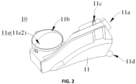
FIG. 2 is a schematic structural diagram of a condenser provided in a first embodiment of the application. -
FIG. 3 is a cross-section view of a part of the condenser shown inFIG. 2 . -
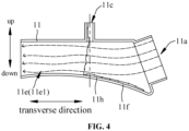
FIG. 4 is a schematic diagram of a part of internal structures of the condenser shown inFIG. 3 , in which arrows with dotted lines indicate an airflow flowing direction, and continuous arrows with solid lines indicate a condensate flowing direction. -
FIG. 5 is a cross-section view of a part of a condenser provided in a second embodiment of the application. -
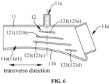
FIG. 6 is a schematic diagram of a part of internal structures of the condenser shown inFIG. 5 . -
FIG. 7 is a schematic diagram of airflow and condensate flowing in the structure shown inFIG. 5 , in which arrows with dotted lines indicate an airflow flowing direction, and continuous arrows with solid lines indicate a condensate flowing direction. -
FIG. 8 is a schematic structural diagram of a condenser provided in a third embodiment of the application. -
FIG. 9 is a schematic structural diagram of a condenser provided in a fourth embodiment of the application, in which continuous arrows with solid lines indicate a condensate flowing direction, and an airflow flowing direction is the same as the airflow flowing direction shown inFIG. 7 . -
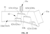
FIG. 10 is a schematic structural diagram of a condenser provided in a fifth embodiment of the application, in which continuous arrows with solid lines indicate a condensate flowing direction, and an airflow flowing direction is the same as the airflow flowing direction shown inFIG. 7 . -
FIG. 11 is a schematic structural diagram of a condenser provided in a sixth embodiment of the application, in which continuous arrows with solid lines indicate a condensate flowing direction, and an airflow flowing direction is the same as the airflow flowing direction shown inFIG. 7 . - It should be noted that embodiments of the application and technical features in the embodiments may be combined with each other without conflict. Detailed descriptions in specific implementations should be understood as an explanation and description of the purpose of the application, and should not be considered as undue limitation of the application.
- In descriptions of the embodiments of the application, orientation or position relationships such as "left" and "right" are based on orientation or position relationships shown in
FIG. 1 , orientation or position relationships such as "transverse direction", "up" and "down" are based on orientation or position relationships shown inFIG. 4 , "vertical direction" is an up-down direction inFIG. 4 . It should be understood that these orientation terms are only intended to facilitate describing the application and simplify descriptions, and are not intended to indicate or imply that the referred device or component must have a specific orientation, or must be configured and operate in a specific orientation, and thus cannot be understood as limitation of the application. - An embodiment of the application provides a
condenser 10. With reference toFIG. 1 to FIG. 4 , thecondenser 10 comprises acondensation pipe 11. Thecondensation pipe 11 is provided with anair inlet 11a, anair outlet 11b, awater inlet 11c, and awater outlet 11d therein. - An
airflow channel 11e extending in a transverse direction is formed between theair inlet 11a and theair outlet 11b. That is, theair inlet 11a and theair outlet 11b are located at two opposite sides of thecondensation pipe 11 in the transverse direction respectively. Airflow flowing from theair inlet 11a into thecondensation pipe 11 may flow along theairflow channel 11e in the transverse direction, and flow out from theair outlet 11b. That is, a path in theairflow channel 11e is an airflow flowing path. It should be noted that theairflow channel 11e described here only needs to extend in the transverse direction, and is not limited to flowing from a specified side to another specified side necessarily. - The
water inlet 11c is located at an upper side of theairflow channel 11e, thewater outlet 11d is located at a lower side of theairflow channel 11e. That is, an arrangement height of thewater inlet 11c is higher than an arrangement height of theairflow channel 11e, and an arrangement height of thewater outlet 11d is lower than the arrangement height of theairflow channel 11e. A condensate flowing path passing through theairflow channel 11e is formed between thewater inlet 11c and thewater outlet 11d. That is, thewater inlet 11c of thecondensation pipe 11 is located at an upper side of thewater outlet 11d, the condensate flowing path formed between thewater inlet 11c and thewater outlet 11d extends from top to bottom, the condensate flowing from thewater inlet 11c into thecondensation pipe 11 falls from the upper side of theairflow channel 11e with an action of its own gravity, and passes through theairflow channel 11e during falling, and flows out from thewater outlet 11d finally. - Specific compositions of the condensate are not limited, and may be water or other types of liquids.
- The
condenser 10 is configured to dehumidify and cool down humid and hot airflow. Specifically, the humid and hot airflow enters thecondensation pipe 11 from theair inlet 11a and flows along theairflow channel 11e, and the condensate enters thecondensation pipe 11 from thewater inlet 11c and flows along the condensate flowing path; when the humid and hot airflow passes through the condensate, the humid and hot airflow exchanges heat with the condensate, the condensate absorbs heat of the humid and hot airflow, vapor in the humid and hot airflow is precipitated from the airflow due to cooling down and is condensed into droplets, the droplets are mixed into the condensate and discharged from the water outlet finally. In this way, an effect of dehumidifying and cooling down the humid and hot airflow is achieved, so that a gas discharged from theair outlet 11b is a relatively low-temperature dry airflow after cooling down and dehumidification. It should be noted that the low-temperature dry airflow is defined relative to the humid and hot airflow, and temperature of the low-temperature dry airflow is lower than temperature of the humid and hot airflow. The low temperature in the embodiment of the application may be room temperature. - The
condenser 10 in the embodiment of the application may be used in any appropriate scenario. Exemplarily, the embodiment of the application is described by taking thecondenser 10 applied to a laundry treatment device as an example. - Exemplarily, with reference to
FIG. 1 , an embodiment of the application provides a laundry treatment device, the laundry treatment device comprises abarrel assembly 20, afiltering device 30, anair guiding device 40, and thecondenser 10 in any one of the embodiments of the application. Thecondenser 10 is arranged at top of thebarrel assembly 20. Thebarrel assembly 20 is provided with a laundry treatment cavity, and an air-in opening and an air-out opening communicated with the laundry treatment cavity. Thefiltering device 30 is communicated with the air-out opening and theair inlet 11a. Theair guiding device 40 is communicated with theair outlet 11b and the air-in opening. It should be noted that theair guiding device 40 is equipped with a fan and a heater therein. - Specifically, the
airflow channel 11e of thecondenser 10 shown inFIG. 1 is arranged in a left-right direction of thebarrel assembly 20. That is, a large part of areas of theairflow channel 11e extends along left and right sides of thebarrel assembly 20. In some implementations, theairflow channel 11e of thecondenser 10 may also be arranged in an axial direction of thebarrel assembly 20. - The
water outlet 11d of thecondenser 10 shown inFIG. 1 is located at a rear side of thebarrel assembly 20 in an axial direction. That is, a part of structures of thecondenser 10 may extend to the rear side of thebarrel assembly 20 in the axial direction, to facilitate water outlet. - An airflow circulation channel is formed in the laundry treatment device, and the
air guiding device 40 guides a dry hot airflow into the laundry treatment cavity through the air-in opening. In the laundry treatment cavity, the dry hot airflow flows through surfaces of wet laundries, exchanges heat and moisture with the wet laundries, absorbs the moisture in the laundries, and turns into a humid and hot airflow. In a process of drying the laundries, lint, impurities or the like produced by the laundries are mixed into the humid and hot airflow. The humid and hot airflow carries the lint and impurities, flows out through the air-out opening sequentially, and then enters thefiltering device 30 to be filtered. A large part of the lint and impurities may be removed from the humid and hot airflow after it is filtered. However, there are still a small number of scraps with small sizes which may enter thecondenser 10 from theair inlet 11a along with the humid and hot airflow. The humid and hot airflow is condensed and dehumidified by the condensate in thecondenser 10, to form a low-temperature dry airflow. The low-temperature dry airflow enters theair guiding device 40 from theair outlet 11b, and is heated by the heater in theair guiding device 40, to form a dry hot airflow. The hot dry airflow enters the laundry treatment cavity again, and the scraps carried in the humid and hot airflow are mixed along with the condensed water into the condensate, and are discharged through thewater outlet 11d. This operates circularly, to achieve continuously and efficiently drying the laundries, filtering and removing the lint. - In the related art, a condenser is usually arranged vertically, with a water inlet, a water outlet, an air inlet and an air outlet arranged in the vertical direction. The air inlet and the water outlet are arranged at a lower position, and the air outlet and the water inlet are arranged at a high position. That is, condensate entering the condenser from the water inlet flows downward in the vertical direction, while humid and hot airflow entering the condenser from the air inlet flows upward in the vertical direction. In a process of flowing upward in the vertical direction, the humid and hot airflow passes the condensate flowing downward in the vertical direction, to achieve a condensation effect. However, this type of condenser requires a large condensate drop and a large airflow flowing distance. Therefore, the condenser has a large volume, occupies a large installation space, and has many structural limitations, especially when some special filtering devices need to be used, it is difficult to install the special filtering devices on the condenser.
- Instead, the
airflow channel 11e of thecondenser 10 in the embodiment of the application extends in the transverse direction, thewater inlet 11c is located at the upper side of theairflow channel 11e, thewater outlet 11d is located at the lower side of theairflow channel 11e, the condensate flowing path formed between thewater inlet 11c and thewater outlet 11d passes through theairflow channel 11e from top to bottom, the condensate flowing along the condensate flowing path flows downward with an action of its own gravity, and exchanges heat with the humid and hot airflow flowing along theairflow channel 11e when it passes through theairflow channel 11e. Since theairflow channel 11e of thecondenser 10 extends in the transverse direction, thecondenser 10 does not require a large airflow flowing distance in the vertical direction, nor does it require a large condensate drop. That is, thecondenser 10 is not affected by the condensate drop and the airflow flowing distance, structures thereof are not only relatively compact, but also are flexible and variable, which may adapt to more functional structures, especially somespecial filtering devices 30. - A relative height between the
air inlet 11a and theair outlet 11b in the embodiment of the application may be adjusted according to requirements. For example, with reference toFIG. 2 andFIG. 3 , an arrangement height of a highest point of theair inlet 11a may be higher than an arrangement height of a lowest point of theair outlet 11b. That is, an arrangement height of at least a part of areas of theair inlet 11a is higher than theair outlet 11b. An arrangement height of only a part of areas of theair inlet 11a shown inFIG. 2 andFIG. 3 is higher than theair outlet 11b, which is equivalent to that a height difference between theair inlet 11a and theair outlet 11b is small, this is beneficial to reduce a height size of thecondensation pipe 11 and save an installation space of thecondensation pipe 11 in a height direction. It should be noted that when theair inlet 11a is arranged vertically or obliquely as shown inFIG. 2 andFIG. 3 , theair inlet 11a has an apparent highest point and an apparent lowest point, while when theair inlet 11a is arranged horizontally (that is, in the same mode as arrangement of theair outlet 11b shown inFIG. 2 andFIG. 3 ), theair inlet 11a has only one arrangement height, and the arrangement height is equivalent to the arrangement height of the highest point of theair inlet 11a. Similarly, when theair outlet 11b is arranged vertically or obliquely, theair outlet 11b has an apparent highest point and an apparent lowest point, while when theair outlet 11b is arranged horizontally as shown inFIG. 2 andFIG. 3 , theair outlet 11b has only one arrangement height, and the arrangement height is equivalent to the arrangement height of the lowest point of theair outlet 11b. - In some embodiments, the arrangement height of the highest point of the
air inlet 11a may be equal to the arrangement height of the lowest point of theair outlet 11b; or, the arrangement height of the highest point of theair inlet 11a may be lower than the arrangement height of the lowest point of theair outlet 11b. - An arrangement position of the
water inlet 11c in the embodiment of the application may be adjusted according to requirements. Preferably, with reference toFIG. 2 to FIG. 4 , thewater inlet 11c may be arranged on a top wall of thecondensation pipe 11. InFIG. 2 to FIG. 4 , a water inlet pipe is arranged on the top wall of thecondensation pipe 11, and an inlet of the water inlet pipe is thewater inlet 11c. In some embodiments, thewater inlet 11c penetrating the top wall may also be formed on the top wall. - A relative height between the
water inlet 11c and theair outlet 11b may also be adjusted according to requirements. For example, with reference toFIG. 2 to FIG. 4 , an arrangement height of a highest point of thewater inlet 11c may be higher than the arrangement height of the lowest point of theair outlet 11b. That is, an arrangement height of at least a part of areas of thewater inlet 11c is higher than theair outlet 11b. It should be noted that definition of the highest point of thewater inlet 11c is the same as definition of the highest point of theair inlet 11a. Both thewater inlet 11c and theair outlet 11b shown inFIG. 2 to FIG. 4 are arranged horizontally. Although an arrangement height of thewhole water inlet 11c is higher than theair outlet 11b, a height difference between thewater inlet 11c and theair outlet 11b is also relatively small. Therefore, it is also beneficial to reduce the height size of thecondensation pipe 11 and save the installation space of thecondensation pipe 11 in the height direction. - In some embodiments, the arrangement height of the highest point of the
water inlet 11c may be equal to the arrangement height of the lowest point of theair outlet 11b; or, the arrangement height of the highest point of thewater inlet 11c may be lower than the arrangement height of the lowest point of theair outlet 11b. - In an embodiment, with reference to
FIG. 3 , thecondensation pipe 11 is provided with apartition wall 11f therein, and thepartition wall 11f separates in thecondensation pipe 11 to form theairflow channel 11e and awater outlet channel 11g located at the lower side of theairflow channel 11e. Thewater outlet channel 11g is provided with thewater outlet 11d, that is, a part of the condensate flowing path passes through thewater outlet channel 11g. A part of edges of thepartition wall 11f inFIG. 3 is arranged at an interval with an inner wall of thecondensation pipe 11, so that a water-passage opening (not shown in the figure) communicated with theairflow channel 11e and thewater outlet channel 11g is formed at the interval. In some embodiments, the water-passage opening may also be directly formed on thepartition wall 11f. After the condensate passes through theairflow channel 11e, the condensate flows from the water-passage opening into thewater outlet channel 11g, and is discharged from thewater outlet 11d. Thewater outlet channel 11g may play a role of collecting the condensate, to discharge the condensate from thewater outlet 11d in time. - Furthermore, with reference to
FIG. 4 , an area where the condensate flowing path passes through theairflow channel 11e may be located downstream of the water-passage opening in an airflow flowing direction, which is equivalent to that the humid and hot airflow flows above the water-passage opening and then passes in the condensate. A part of areas at a side of thepartition wall 11f facing theairflow channel 11e forms aflow guiding surface 11h, and theflow guiding surface 11h guides the condensate flowing path to extend toward the water-passage opening. Theflow guiding surface 11h inFIG. 4 is a curved surface. In some implementations, theflow guiding surface 11h may also be an oblique plane. After the condensate passing through theairflow channel 11e falls onto theflow guiding surface 11h, it may flow toward the water-passage opening along theflow guiding surface 11h, which is equivalent to that a flowing direction of the condensate flowing along theflow guiding surface 11h is opposite to the airflow flowing direction, so that the condensate may be prevented from flowing toward theair outlet 11b along with the low-temperature dry airflow formed after condensation as much as possible. - In an embodiment, with reference to
FIG. 2 andFIG. 3 , theairflow channel 11e may also be provided with a first extension section 11e1 and a second extension section 11e2. The second extension section 11e2 is communicated with the first extension section 11e1 and extends toward a side of the first extension section 11e1. That is, an included angle is present between the second extension section 11e2 and the first extension section 11e1. An end of the first extension section 11e1 away from the second extension section 11e2 is provided with theair inlet 11a, an end of the second extension section 11e2 away from the first extension section 11e1 is provided with theair outlet 11b, and the condensate flowing path passes through the first extension section 11e1. - Specifically, in order to facilitate descriptions, it may be considered that the first extension section 11e1 extends in a length direction of the
condensation pipe 11, and the second extension section 11e2 extends in a width direction of thecondensation pipe 11. The second extension section 11e2 is provided, which is equivalent to saving a length of thecondensation pipe 11, so that overall structures of thecondenser 10 may be more compact. Furthermore, the low-temperature dry airflow formed after condensation may also carry tiny droplets formed by a small amount of condensate. Therefore, the first extension section 11e1 and the second extension section 11e2 are provided, a corner may be formed at a position where the first extension section 11e1 is communicated with the second extension section 11e2. When the low-temperature dry airflow flows through the position where the first extension section 11e1 is communicated with the second extension section 11e2, the tiny droplets carried in the low-temperature dry airflow may be thrown to a side wall of theairflow channel 11e with an action of centrifugal force, so that the condensate may also be prevented from flowing toward theair outlet 11b along with the airflow as much as possible. - In an embodiment, with reference to
FIG. 5 to FIG. 11 , thecondenser 10 further comprises aflow guiding assembly 12, theflow guiding assembly 12 is arranged in theairflow channel 11e and is located on the condensate flowing path. When the condensate flows through theflow guiding assembly 12, theflow guiding assembly 12 may guide flow of the condensate, so that the humid and hot airflow may fully come into contact with the condensate, therefore condensation, filtration and lint removal effects of thecondenser 10 may be improved. - The
flow guiding assembly 12 may be formed in multiple structures. Exemplarily, with reference toFIG. 5 to FIG. 11 , theflow guiding assembly 12 comprises aflow guiding plate 121, theflow guiding plate 121 guides the condensate to flow toward at least one of two opposite sides of theflow guiding plate 121 in an airflow flowing direction. - Specifically, the
flow guiding assembly 12 shown inFIG. 5 to FIG. 11 is provided with multipleflow guiding plates 121, and each of theflow guiding plates 121 is arranged at a respective interval. In some embodiments, theflow guiding assembly 12 may also be provided with only oneflow guiding plate 121. Shape of theflow guiding plate 121 shown inFIG. 5 to FIG. 11 is substantially a rectangular shape. It may be understood that the shape of theflow guiding plate 121 is not limited to the rectangular shape. In some embodiments, the shape of theflow guiding plate 121 may also be a round shape, an elliptical shape, a trapezoidal shape, a triangular shape, special-shaped, etc. Theflow guiding plate 121 may guide the condensate to flow toward two opposite sides of theflow guiding plate 121 in the airflow flowing direction. It should be noted that the airflow flowing direction refers to a direction in which the airflow flows along the airflow flowing path. That is, after the condensate flows down from two opposite sides of theflow guiding plate 121 in the airflow flowing direction, water curtains may be formed at two opposite sides of theflow guiding plate 121 in the airflow flowing direction respectively. Theflow guiding plate 121 may also guide the condensate to flow toward only one of two opposite sides of theflow guiding plate 121 in the airflow flowing direction, which is equivalent to after the condensate flows down from one of two opposite sides of theflow guiding plate 121 in the airflow flowing direction, a water curtain may be formed only at the side where the condensate flows down. For example, with continuous reference toFIG. 5 to FIG. 7 , fourflow guiding plates 121 are shown inFIG. 5 to FIG. 7 . In order to facilitate descriptions, the fourflow guiding plates 121 shown inFIG. 5 to FIG. 7 are referred to as a firstflow guiding plate 121a, a secondflow guiding plate 121b, a thirdflow guiding plate 121c, and a fourthflow guiding plate 121d respectively. Each of the firstflow guiding plate 121a, the secondflow guiding plate 121b and the thirdflow guiding plate 121c may guide the condensate to flow toward two opposite sides of theflow guiding plate 121 in the airflow flowing direction, and the condensate flowing down from each of the firstflow guiding plate 121a, the secondflow guiding plate 121b and the thirdflow guiding plate 121c forms water curtains at two opposite sides of each of the firstflow guiding plate 121a, the secondflow guiding plate 121b and the thirdflow guiding plate 121c in the airflow flowing direction respectively. Furthermore, the fourthflow guiding plate 121d may guide the condensate to flow toward one of two opposite sides of theflow guiding plate 121 in the airflow flowing direction, and the condensate flowing down from the fourthflow guiding plate 121d forms a water curtain only at the side where the condensate flows down. The water curtain may increase a contact area between the humid and hot airflow and the condensate, so that the humid and hot airflow may fully exchange heat with the condensate, therefore the condensation effect may be improved. Furthermore, when theflow guiding plate 121 guides the condensate to flow toward two opposite sides of theflow guiding plate 121 in the airflow flowing direction, the humid and hot airflow may be allowed to pass through at least two water curtains. That is, compared with theflow guiding plate 121 guiding the condensate to flow toward one of two opposite sides of theflow guiding plate 121 in the airflow flowing direction, when theflow guiding plate 121 guides the condensate to flow toward two opposite sides of theflow guiding plate 121 in the airflow flowing direction, a number of water curtains may be increased, so that the humid and hot airflow may come into contact with the water curtains more fully, therefore condensation, filtration and lint removal effects may be further improved. - It should be noted that the
flow guiding assembly 12 shown inFIG. 5 to FIG. 7 actually indicates that a part of multipleflow guiding plates 121 guide the condensate to flow toward two opposite sides of theflow guiding plate 121 in the airflow flowing direction, another part of theflow guiding plates 121 guide the condensate to flow toward one of two opposite sides of theflow guiding plate 121 in the airflow flowing direction. It may be understood that in some implementations, when theflow guiding assembly 12 is provided with multipleflow guiding plates 121, each of theflow guiding plates 121 may guide the condensate to flow toward two opposite sides of theflow guiding plate 121 in the airflow flowing direction, or each of theflow guiding plates 121 may guide the condensate to flow toward one of two opposite sides of theflow guiding plate 121 in the airflow flowing direction. When theflow guiding assembly 12 is provided with only oneflow guiding plate 121, theflow guiding plate 121 may be configured to guide the condensate to flow toward two opposite sides of theflow guiding plate 121 in the airflow flowing direction, or may be configured to guide the condensate to flow toward one of two opposite sides of theflow guiding plate 121 in the airflow flowing direction. - With reference to
FIG. 6 andFIG. 7 , a flow guiding surface of theflow guiding plate 121 may be obliquely arranged downward from a side located downstream in the airflow flowing direction to a side located upstream in the airflow flowing direction. That is, the humid and hot airflow may not only come into contact with the water curtain, but also may come into contact with condensate on the flow guiding surface, so that the contact area between the humid and hot airflow and the condensate may also be increased, to further improve condensation, filtration and lint removal effects. - It may be understood that the flow guiding surface is not limited to be obliquely arranged downward from the side located downstream in the airflow flowing direction to the side located upstream in the airflow flowing direction. For example, in some embodiments, the flow guiding surface may also be arranged horizontally.
- In an embodiment, with reference to
FIG. 8 , theflow guiding plate 121 may also be formed with aflow collection groove 121e thereon, and theflow collection groove 121e may collect the condensate, so that it may not only slow down a flow rate of the condensate, but also may allow a part of the humid and hot airflow flowing along the airflow flowing path to fully come into contact with the condensate in theflow collection groove 121e, therefore condensation, filtration and lint removal effects may also be improved. - The
flow collection groove 121e may be formed in multiple modes. Exemplarily, with reference toFIG. 8 , the flow guiding surface of theflow guiding plate 121 may define theflow collection groove 121e. That is, theflow collection groove 121e may be configured by using a non-planar flow guiding surface, for example, the flow guiding surface may configure theflow collection groove 121e by bending theflow guiding plate 121. Specifically, the flow guiding surface of theflow guiding plate 121 shown inFIG. 8 is a curved surface bent to be close to a bottom end surface of theflow guiding plate 121. In some embodiments, the flow guiding surface may further comprise a first oblique surface and a second oblique surface connected to each other, both the first oblique surface and the second oblique surface may be oblique planes; or, one of the first oblique surface and the second oblique surface may be an oblique plane, and another one of the first oblique surface and the second oblique surface may be an oblique curved surface, and theflow collection groove 121e is defined between the first oblique surface and the second oblique surface. - In some embodiments, a part of areas at top of the
flow guiding plate 121 may be recessed to form theflow collection groove 121e. - In the
flow guiding assembly 12 shown inFIG. 8 , threeflow guiding plates 121 are provided thereon withflow collection grooves 121e respectively, and the lastflow guiding plate 121 along a condensate flowing direction is not provided with a respectiveflow collection groove 121e. It may be understood that arrangement positions, number or the like offlow guiding plates 121 without providingflow collection grooves 121e may be adjusted according to requirements. In some embodiments, all theflow guiding plates 121 may be provided withflow collection grooves 121e respectively; or, none of theflow guiding plates 121 may be provided withflow collection grooves 121e respectively. - A relative position between the
flow guiding plate 121 and thewater inlet 11c may be determined according to requirements, as long as the condensate flowing from thewater inlet 11c into thecondensation pipe 11 may flow to theflow guiding plate 121. Exemplarily, with reference toFIG. 6 , the relative position between theflow guiding plate 121 and thewater inlet 11c may be: an axial center line of thewater inlet 11c passes through theflow guiding plate 121, that is, an arrangement mode of the firstflow guiding plate 121a, the secondflow guiding plate 121b and the thirdflow guiding plate 121c inFIG. 6 . The relative position between theflow guiding plate 121 and thewater inlet 11c may also be: theflow guiding plate 121 is located at one of two opposite sides of the axial center line of thewater inlet 11c in the airflow flowing direction, that is, an arrangement mode of the fourthflow guiding plate 121d inFIG. 6 . - Multiple
flow guiding plates 121 may be arranged at respective intervals in thecondensation pipe 11 in multiple modes. Exemplarily, with reference toFIG. 5 to FIG. 7 , each of theflow guiding plates 121 may be arranged in a respective layer in a vertical direction, that is, each of theflow guiding plates 121 may be sequentially arranged at a respective interval in the vertical direction, to form a multi-layer structure. - Further, with reference to
FIG. 6 to FIG. 11 , in case of theflow guiding plate 121 with the multi-layer structure, relative positions of at least someflow guiding plates 121 adjacent in the vertical direction may satisfy that along a condensate flowing direction, theflow guiding plate 121 located downstream may receive at least a part of condensate flowing down from theflow guiding plate 121 located upstream. That is, relative positions of at least twoflow guiding plates 121 adjacent in the vertical direction satisfy that at least a part of condensate flowing down from one of theflow guiding plates 121 may flow to anotherflow guiding plate 121 located at a lower side of this oneflow guiding plate 121 and adjacent thereto. - Specifically, taking the first
flow guiding plate 121a and the secondflow guiding plate 121b inFIG. 6 andFIG. 7 as an example, the firstflow guiding plate 121a and the secondflow guiding plate 121b are arranged to be adjacent in the vertical direction, the firstflow guiding plate 121a is located upstream of the secondflow guiding plate 121b along the condensate flowing direction, and a horizontal projection of the firstflow guiding plate 121a is located within an area of a horizontal projection of the secondflow guiding plate 121b. It should be noted that the horizontal projection refers to a projection on a horizontal plane perpendicular to the vertical direction. That is, the condensate on the firstflow guiding plate 121a may flow from two opposite sides of the firstflow guiding plate 121a in the airflow flowing direction to the secondflow guiding plate 121b respectively, which is equivalent to that all the condensate flowing down from the firstflow guiding plate 121a flows to the secondflow guiding plate 121b. Similarly, the secondflow guiding plate 121b and the thirdflow guiding plate 121c are arranged to be adjacent in the vertical direction, the secondflow guiding plate 121b is located upstream of the thirdflow guiding plate 121c along the condensate flowing direction, and a horizontal projection of the secondflow guiding plate 121b is located within an area of a horizontal projection of the thirdflow guiding plate 121c, which is equivalent to that all the condensate flowing down from the secondflow guiding plate 121b flows to the thirdflow guiding plate 121c. With continuous reference toFIG. 6 andFIG. 7 , the thirdflow guiding plate 121c and the fourthflow guiding plate 121d are arranged to be adjacent in the vertical direction, the thirdflow guiding plate 121c is located upstream of the fourthflow guiding plate 121d along the condensate flowing direction, and a horizontal projection of only one of two opposite sides of the thirdflow guiding plate 121c in the airflow flowing direction is located within an area of a horizontal projection of the fourthflow guiding plate 121d. Therefore, only a part of the condensate flowing down from the thirdflow guiding plate 121c flows to the fourthflow guiding plate 121d, another part of the condensate does not pass through the fourthflow guiding plate 121d and flows toward thewater outlet 11d directly. In other words, only a part of the condensate flowing down from the thirdflow guiding plate 121c flows to the fourthflow guiding plate 121d. - It should be noted that the first
flow guiding plate 121a, the secondflow guiding plate 121b and the thirdflow guiding plate 121c are not limited to using the arrangement mode shown inFIG. 6 andFIG. 7 . For example, in another embodiment, with reference toFIG. 9 , in order to facilitate descriptions, two opposite sides of theflow guiding plate 121 in the airflow flowing direction may be referred to as a first side and a second side respectively. InFIG. 9 , the first side is located upstream of the second side in the airflow flowing direction. In some embodiments, the first side may also be located downstream of the second side in the airflow flowing direction, which is equivalent to that positions of the first side and the second side may be interchanged. InFIG. 9 , a horizontal projection of the first side of the firstflow guiding plate 121a is located within an area of a horizontal projection of the secondflow guiding plate 121b, and both a horizontal projection of the second side of the firstflow guiding plate 121a and a horizontal projection of the second side of the secondflow guiding plate 121b are located within an area of a horizontal projection of the thirdflow guiding plate 121c, which is equivalent to that the condensate flowing down from the first side of the firstflow guiding plate 121a flows to the secondflow guiding plate 121b, the condensate flowing down from the second side of the firstflow guiding plate 121a and the second side of the secondflow guiding plate 121b flows to the thirdflow guiding plate 121c, while the condensate flowing down from the first side of the secondflow guiding plate 121b does not flow to the thirdflow guiding plate 121c. That is, theflow guiding plate 121 located downstream along the condensate flowing direction may receive a part of condensate flowing down from theflow guiding plate 121 located upstream and adjacent thereto. - In the
flow guiding assembly 12 shown inFIG. 6 andFIG. 9 , theflow guiding plate 121 located downstream may receive at least a part of condensate flowing down from theflow guiding plate 121 located upstream and adjacent thereto. In another embodiment, with reference toFIG. 10 , relative positions among the firstflow guiding plate 121a, the secondflow guiding plate 121b and the thirdflow guiding plate 121c may also be: a horizontal projection of the first side of the firstflow guiding plate 121a is located within an area of a horizontal projection of the secondflow guiding plate 121b, a horizontal projection of the second side of the firstflow guiding plate 121a is located within an area of a horizontal projection of the thirdflow guiding plate 121c, and a horizontal projection of the second side of the secondflow guiding plate 121b offsets from a horizontal projection of the first side of the thirdflow guiding plate 121c. That is, the condensate flowing down from the first side of the firstflow guiding plate 121a flows to the secondflow guiding plate 121b, the condensate flowing down from the second side of the firstflow guiding plate 121a flows to the thirdflow guiding plate 121c, while the condensate flowing down from the second side of the secondflow guiding plate 121b does not flow to the thirdflow guiding plate 121c, instead, avoids the thirdflow guiding plate 121c and continues to flow down. That is, the secondflow guiding plate 121b may receive a part of the condensate flowing down from the firstflow guiding plate 121a located upstream and adjacent thereto, while the thirdflow guiding plate 121c does not receive the condensate flowing down from the secondflow guiding plate 121b located upstream and adjacent thereto, which is equivalent to that relative positions of only someflow guiding plates 121 adjacent in the vertical direction from multipleflow guiding plates 121 satisfy: along the condensate flowing direction, theflow guiding plate 121 located downstream may receive at least a part of condensate flowing down from theflow guiding plate 121 located upstream. - The
flow guiding plate 121 located downstream along the condensate flowing direction receives at least a part of condensate flowing down from theflow guiding plate 121 located upstream and adjacent thereto, which may not only form a water curtain between two adjacentflow guiding plates 121, but also may slow down a flow rate of the condensate, therefore condensation, filtration and lint removal effects may be further improved. Especially when at least someflow guiding plates 121 from multipleflow guiding plates 121 may also guide the condensate to flow toward two opposite sides of theflow guiding plates 121 in the airflow flowing direction, condensation, filtration and lint removal effects of thecondenser 10 may be improved greatly. - Furthermore, with reference to
FIG. 10 , although the thirdflow guiding plate 121c inFIG. 10 does not receive the condensate flowing down from the secondflow guiding plate 121b located upstream and adjacent thereto, the condensate flowing down from the second side of the secondflow guiding plate 121b also forms a water curtain separately. That is, compared with theflow guiding assembly 12 shown inFIG. 6 , theflow guiding assembly 12 shown inFIG. 9 adds a number of water curtains at a lower side of the thirdflow guiding plate 121c, therefore condensation, filtration and lint removal effects of thecondenser 10 may also be improved. - In the multi-layer structure used by the
flow guiding assembly 12 shown inFIG. 5 to FIG. 10 , only oneflow guiding plate 121 is arranged in each layer. In another embodiment, with reference toFIG. 11 , theflow guiding assembly 12 may also be: some of multipleflow guiding plates 121 are arranged in respective layers in the vertical direction, and some of multipleflow guiding plates 121 are arranged at respective intervals in the transverse direction. That is, theflow guiding assembly 12 shown inFIG. 11 also uses a multi-layer structure, however, compared with theflow guiding assembly 12 shown inFIG. 5 to FIG. 10 , at least twoflow guiding plates 121 may be arranged in at least one of layers of theflow guiding assembly 12 shown inFIG. 11 , and at least twoflow guiding plates 121 in the same layer are arranged at respective intervals in the transverse direction. It should be noted that theflow guiding assembly 12 shown inFIG. 11 may use theflow guiding plate 121 described in any one of the previous embodiments, which are not elaborated here. - In an embodiment, the
barrel assembly 20 comprises a drum and a tub. The drum is rotatably arranged in the tub, and thecondenser 10 as described above is connected to the tub. - The drum may be a non-porous drum or a porous drum. When the drum is a porous drum, it relies on the tub to receive water. When the drum is a non-porous drum, it relies on the drum itself to receive water. That is, the drum may receive both water and laundries therein. Water in the drum does not enter the tub in washing processes; water is discharged through the tub in water outlet processes.
- It should be noted that the laundry treatment device in the embodiment of the application may be a clothes dryer, an integrated washing and drying machine, or the like, which is not limited here. The laundry treatment device may be a drum-type laundry treatment device or a pulsator-type laundry treatment device.
- Various embodiments/implementations provided in the application may be combined with each other without conflict.
- The above descriptions are only preferred embodiments of the application, and are not intended to limit the application. The application may have various modifications and variations for those skilled in the art. Any modification, equivalent replacement, improvement, or the like made within the spirit and principle of the application are comprised in the scope of protection of the application.
Claims (13)
- A condenser, comprising:
a condensation pipe (11), provided with an air inlet (11a), an air outlet (11b), a water inlet (11c) and a water outlet (11d), an airflow channel (11e) extending in a transverse direction being formed between the air inlet (11a) and the air outlet (11b), the water inlet (11c) being located at an upper side of the airflow channel (11e), the water outlet (11d) being located at a lower side of the airflow channel (11e), a condensate flowing path passing through the airflow channel (11e) being formed between the water inlet (11c) and the water outlet (11d). - The condenser of claim 1, wherein a height of a highest point of the air inlet (11a) is equal to or higher than a height of a lowest point of the air outlet (11b),
a height of a highest point of the water inlet (11c) is equal to or higher than the height of the lowest point of the air outlet (11b). - The condenser of claim 1 or 2, wherein the condensation pipe (11) is provided with a partition wall (11f) therein, the airflow channel (11e) and a water outlet channel (11g) located at the lower side of the airflow channel (11e) is separated by the partition wall (11f) in the condensation pipe (11), and the water outlet channel (11g) is provided with the water outlet (11d),
the partition wall (11f) is provided thereon with a water-passage opening connecting the airflow channel (11e) and the water outlet channel (11g); or, a part of edges of the partition wall (11f) is spaced from an inner wall of the condensation pipe (11) to form at the spacing the water-passage opening connecting the airflow channel (11e) and the water outlet channel (11g). - The condenser of claim 3, wherein an area where the condensate flowing path passes through the airflow channel (11e) is located downstream of the water-passage opening in an airflow flowing direction, a part of an area at a side of the partition wall (11f) facing the airflow channel (11e) forms a flow guiding surface (11h), and the flow guiding surface (11h) guides the condensate flowing path to extend toward the water-passage opening.
- The condenser of claim 1 or 2, wherein the airflow channel (11e) is provided with a first extension section (11e1) and a second extension section (11e2),
the second extension section (11e2) is communicated with the first extension section (11e1) and extends toward a side of the first extension section (11e1), an end of the first extension section (11e1) away from the second extension section (11e2) is provided with the air inlet (11a), an end of the second extension section (11e2) away from the first extension section (11e1) is provided with the air outlet (11b), and the condensate flowing path passes through the first extension section (11e1). - The condenser of claim 1 or 2, further comprising a flow guiding assembly (12) arranged in the airflow channel (11e), and the flow guiding assembly (12) being located on the condensate flowing path to guide flow of condensate flowing along the condensate flowing path.
- The condenser of claim 6, wherein the flow guiding assembly (12) comprises: a flow guiding plate (121), guiding the condensate to flow toward at least one of two opposite sides of the flow guiding plate (121) in an airflow flowing direction.
- The condenser of claim 6, wherein the flow guiding plate (121) is provided with a flow collection groove (121e) thereon.
- The condenser of claim 6, wherein the flow guiding assembly (12) comprises a plurality of flow guiding plates (121), and the flow guiding plates (121) are arranged at intervals.
- The condenser of claim 9, wherein each of the flow guiding plates (121) is arranged in a layer in a vertical direction; or
a part of the plurality of flow guiding plates (121) are arranged in respective layers in the vertical direction, and a part of the plurality of flow guiding plates (121) are arranged at respective intervals in the transverse direction. - The condenser of claim 10, wherein relative positions of at least some adjacent flow guiding plates (121) in the vertical direction from the plurality of flow guiding plates (121) satisfy that along a condensate flowing direction, the flow guiding plate (121) located downstream is able to receive at least a part of condensate flowing down from the flow guiding plate (121) located upstream.
- A laundry treatment device, comprising:a barrel assembly (20), provided with a laundry treatment cavity, and with an air-in opening and an air-out opening communicating with the laundry treatment cavity respectively;a condenser (10) of any one of claims 1 to 11, arranged at a top of the barrel assembly (20);a filtering device (30), connecting the air-out opening and an air inlet (11a); andan air guiding device (40), connecting the air outlet (11b) and an air-in opening.
- The laundry treatment device of claim 12, wherein an airflow channel (11e) is arranged in a direction extending from a left side to a right side of the barrel assembly (20); and/or
a water outlet (11d) is located at a rear side of the barrel assembly (20) in an axial direction.
Applications Claiming Priority (2)
| Application Number | Priority Date | Filing Date | Title |
|---|---|---|---|
| CN202210284855.6A CN114657740B (en) | 2022-03-22 | 2022-03-22 | A condenser and clothing treatment equipment |
| PCT/CN2023/082609 WO2023179568A1 (en) | 2022-03-22 | 2023-03-20 | Condenser and laundry treatment device |
Publications (2)
| Publication Number | Publication Date |
|---|---|
| EP4491792A1 true EP4491792A1 (en) | 2025-01-15 |
| EP4491792A4 EP4491792A4 (en) | 2025-06-25 |
Family
ID=82030480
Family Applications (1)
| Application Number | Title | Priority Date | Filing Date |
|---|---|---|---|
| EP23773815.8A Pending EP4491792A4 (en) | 2022-03-22 | 2023-03-20 | Condenser and laundry treatment device |
Country Status (3)
| Country | Link |
|---|---|
| EP (1) | EP4491792A4 (en) |
| CN (1) | CN114657740B (en) |
| WO (1) | WO2023179568A1 (en) |
Families Citing this family (4)
| Publication number | Priority date | Publication date | Assignee | Title |
|---|---|---|---|---|
| CN114657740B (en) * | 2022-03-22 | 2023-12-01 | 无锡小天鹅电器有限公司 | A condenser and clothing treatment equipment |
| CN114703643B (en) * | 2022-03-22 | 2023-11-28 | 无锡小天鹅电器有限公司 | Condensing assembly and clothes treatment equipment |
| CN114737374A (en) * | 2022-03-22 | 2022-07-12 | 无锡小天鹅电器有限公司 | Condensing device and clothes treatment equipment |
| CN120231224A (en) * | 2023-12-28 | 2025-07-01 | 合肥美的洗衣机有限公司 | Condensers, drying systems and clothing processing equipment |
Family Cites Families (14)
| Publication number | Priority date | Publication date | Assignee | Title |
|---|---|---|---|---|
| DE2214618C3 (en) * | 1971-09-17 | 1981-07-23 | Bosch-Siemens Hausgeräte GmbH, 7000 Stuttgart | Clothes dryer |
| DE2148127C3 (en) * | 1971-09-17 | 1982-05-06 | Bosch-Siemens Hausgeräte GmbH, 7000 Stuttgart | Clothes dryer |
| US3866333A (en) * | 1971-09-17 | 1975-02-18 | Siemens Elektrogeraete Gmbh | Dehumidifier for air utilized in laundry drying |
| DE2931824C2 (en) * | 1979-08-06 | 1982-04-22 | Bosch-Siemens Hausgeräte GmbH, 7000 Stuttgart | Household clothes dryer |
| CN110344225A (en) * | 2015-04-29 | 2019-10-18 | 博西华电器(江苏)有限公司 | Dryer |
| CN106192325B (en) * | 2015-04-29 | 2020-06-12 | 博西华电器(江苏)有限公司 | Electric clothes dryer |
| CN204803583U (en) * | 2015-05-06 | 2015-11-25 | 博西华电器(江苏)有限公司 | Clothe nursing machine |
| CN207259818U (en) * | 2017-08-14 | 2018-04-20 | 苏州三星电子有限公司 | A kind of roller washing machine condenser and drying unit |
| KR102655369B1 (en) * | 2018-12-27 | 2024-04-08 | 삼성전자주식회사 | Laundry treating apparatus |
| CN112647263B (en) * | 2019-10-12 | 2025-03-18 | 佛山市云米电器科技有限公司 | Condenser, drying device and clothing care device for clothing care |
| CN212152849U (en) * | 2020-02-11 | 2020-12-15 | 青岛海尔滚筒洗衣机有限公司 | Clothes treatment equipment and deposition condenser thereof |
| CN114657740B (en) * | 2022-03-22 | 2023-12-01 | 无锡小天鹅电器有限公司 | A condenser and clothing treatment equipment |
| CN114737374A (en) * | 2022-03-22 | 2022-07-12 | 无锡小天鹅电器有限公司 | Condensing device and clothes treatment equipment |
| CN114703643B (en) * | 2022-03-22 | 2023-11-28 | 无锡小天鹅电器有限公司 | Condensing assembly and clothes treatment equipment |
-
2022
- 2022-03-22 CN CN202210284855.6A patent/CN114657740B/en active Active
-
2023
- 2023-03-20 EP EP23773815.8A patent/EP4491792A4/en active Pending
- 2023-03-20 WO PCT/CN2023/082609 patent/WO2023179568A1/en not_active Ceased
Also Published As
| Publication number | Publication date |
|---|---|
| CN114657740A (en) | 2022-06-24 |
| EP4491792A4 (en) | 2025-06-25 |
| CN114657740B (en) | 2023-12-01 |
| WO2023179568A1 (en) | 2023-09-28 |
Similar Documents
| Publication | Publication Date | Title |
|---|---|---|
| CN114657740B (en) | A condenser and clothing treatment equipment | |
| CN106852673B (en) | Heat pump type dish washing machine | |
| CN114703643B (en) | Condensing assembly and clothes treatment equipment | |
| WO2023179564A1 (en) | Condensing device and clothes treating apparatus | |
| CN105937168A (en) | Clothes drying machine or washing and drying integrated machine | |
| EP3252225A1 (en) | Base of heat pump system and heat pump system for drier or washer-drier | |
| CN107447471B (en) | Base of heat pump system and heat pump system for clothes dryer or washing and drying integrated machine | |
| EP4296423B1 (en) | A condenser for a washing-drying integrated machine and washing-drying integrated machine | |
| CN205775467U (en) | The pedestal of heat pump and for dryer or the heat pump of washing-drying integral machine | |
| CN220767471U (en) | Base device and clothes treatment equipment | |
| CN106676859A (en) | Heat exchanger cleaning nozzle, heat pump dryer cleaning device and heat pump clothes dryer | |
| CN223481535U (en) | Condenser and clothes treatment equipment | |
| EP4467711A1 (en) | Condensation channel for drying apparatus, and drying apparatus | |
| JP7301835B2 (en) | Dehumidification drying unit and washer/dryer | |
| CN115704173A (en) | Condenser and clothes treatment equipment with same | |
| CN115821554B (en) | Drying equipment | |
| CN217127825U (en) | Condensing equipment and clothing treatment facility | |
| CN223292823U (en) | Base device and clothing processing equipment | |
| CN223134818U (en) | Base device and clothing processing equipment | |
| CN223163651U (en) | Base device and clothes treatment equipment | |
| CN223458569U (en) | Condenser and clothes treatment equipment | |
| CN112726158B (en) | Condenser and clothes treatment equipment | |
| CN223468597U (en) | Clothes treatment device | |
| CN119711129B (en) | Base and clothes treatment equipment | |
| CN118621548A (en) | Two-device assembly and clothes processing device |
Legal Events
| Date | Code | Title | Description |
|---|---|---|---|
| STAA | Information on the status of an ep patent application or granted ep patent |
Free format text: STATUS: THE INTERNATIONAL PUBLICATION HAS BEEN MADE |
|
| PUAI | Public reference made under article 153(3) epc to a published international application that has entered the european phase |
Free format text: ORIGINAL CODE: 0009012 |
|
| STAA | Information on the status of an ep patent application or granted ep patent |
Free format text: STATUS: REQUEST FOR EXAMINATION WAS MADE |
|
| 17P | Request for examination filed |
Effective date: 20241010 |
|
| AK | Designated contracting states |
Kind code of ref document: A1 Designated state(s): AL AT BE BG CH CY CZ DE DK EE ES FI FR GB GR HR HU IE IS IT LI LT LU LV MC ME MK MT NL NO PL PT RO RS SE SI SK SM TR |
|
| A4 | Supplementary search report drawn up and despatched |
Effective date: 20250527 |
|
| DAV | Request for validation of the european patent (deleted) | ||
| DAX | Request for extension of the european patent (deleted) | ||
| RIC1 | Information provided on ipc code assigned before grant |
Ipc: D06F 25/00 20060101ALN20250521BHEP Ipc: D06F 58/24 20060101AFI20250521BHEP |