EP4491790A1 - Dispenser assembly, detergent box and clothing treatment machine - Google Patents
Dispenser assembly, detergent box and clothing treatment machine Download PDFInfo
- Publication number
- EP4491790A1 EP4491790A1 EP22934626.7A EP22934626A EP4491790A1 EP 4491790 A1 EP4491790 A1 EP 4491790A1 EP 22934626 A EP22934626 A EP 22934626A EP 4491790 A1 EP4491790 A1 EP 4491790A1
- Authority
- EP
- European Patent Office
- Prior art keywords
- water
- water treatment
- treatment device
- opening
- dispenser
- Prior art date
- Legal status (The legal status is an assumption and is not a legal conclusion. Google has not performed a legal analysis and makes no representation as to the accuracy of the status listed.)
- Pending
Links
Images




Classifications
-
- D—TEXTILES; PAPER
- D06—TREATMENT OF TEXTILES OR THE LIKE; LAUNDERING; FLEXIBLE MATERIALS NOT OTHERWISE PROVIDED FOR
- D06F—LAUNDERING, DRYING, IRONING, PRESSING OR FOLDING TEXTILE ARTICLES
- D06F39/00—Details of washing machines not specific to a single type of machines covered by groups D06F9/00 - D06F27/00
- D06F39/007—Arrangements of water softeners
-
- D—TEXTILES; PAPER
- D06—TREATMENT OF TEXTILES OR THE LIKE; LAUNDERING; FLEXIBLE MATERIALS NOT OTHERWISE PROVIDED FOR
- D06F—LAUNDERING, DRYING, IRONING, PRESSING OR FOLDING TEXTILE ARTICLES
- D06F39/00—Details of washing machines not specific to a single type of machines covered by groups D06F9/00 - D06F27/00
-
- D—TEXTILES; PAPER
- D06—TREATMENT OF TEXTILES OR THE LIKE; LAUNDERING; FLEXIBLE MATERIALS NOT OTHERWISE PROVIDED FOR
- D06F—LAUNDERING, DRYING, IRONING, PRESSING OR FOLDING TEXTILE ARTICLES
- D06F39/00—Details of washing machines not specific to a single type of machines covered by groups D06F9/00 - D06F27/00
- D06F39/02—Devices for adding soap or other washing agents
-
- D—TEXTILES; PAPER
- D06—TREATMENT OF TEXTILES OR THE LIKE; LAUNDERING; FLEXIBLE MATERIALS NOT OTHERWISE PROVIDED FOR
- D06F—LAUNDERING, DRYING, IRONING, PRESSING OR FOLDING TEXTILE ARTICLES
- D06F39/00—Details of washing machines not specific to a single type of machines covered by groups D06F9/00 - D06F27/00
- D06F39/06—Arrangements for preventing or destroying scum
-
- D—TEXTILES; PAPER
- D06—TREATMENT OF TEXTILES OR THE LIKE; LAUNDERING; FLEXIBLE MATERIALS NOT OTHERWISE PROVIDED FOR
- D06F—LAUNDERING, DRYING, IRONING, PRESSING OR FOLDING TEXTILE ARTICLES
- D06F39/00—Details of washing machines not specific to a single type of machines covered by groups D06F9/00 - D06F27/00
- D06F39/08—Liquid supply or discharge arrangements
-
- D—TEXTILES; PAPER
- D06—TREATMENT OF TEXTILES OR THE LIKE; LAUNDERING; FLEXIBLE MATERIALS NOT OTHERWISE PROVIDED FOR
- D06F—LAUNDERING, DRYING, IRONING, PRESSING OR FOLDING TEXTILE ARTICLES
- D06F39/00—Details of washing machines not specific to a single type of machines covered by groups D06F9/00 - D06F27/00
- D06F39/10—Filtering arrangements
Definitions
- the application relates to the technical field of clothing treatment, and in particular to a dispenser assembly, a detergent box and a clothing treatment machine.
- a water treatment module is arranged inside a clothing treatment machine, and is configured to perform scale inhibition and/or sterilization or other treatments on tap water, and then send the treated water into a washing drum.
- the water treatment module is arranged inside the clothing treatment machine, as usage time increases, water treatment effects become worse and worse, while a user cannot replace the water treatment module.
- the application is desired to provide a dispenser assembly, a detergent box and a clothing treatment machine which facilitate replacement of a water treatment device.
- An aspect of the application provides a dispenser assembly, the dispenser assembly comprises a dispenser and a water treatment device.
- the dispenser is formed with a replacement opening, a placement groove and a liquid discharge opening, both the replacement opening and the liquid discharge opening are communicated with the placement groove.
- the water treatment device is detachably arranged in the placement groove, and is formed with a water inlet, a water outlet, and a reagent cavity receiving a water treatment agent, both the water inlet and the water outlet are communicated with the reagent cavity, and the water outlet is communicated with the placement groove.
- the dispenser assembly may comprise elastic bodies, the elastic bodies are arranged on at least one side surface of the placement groove and abut against the water treatment device tightly.
- an end of the elastic body may be connected to the dispenser, another end of the elastic body may be a free end extending into the placement groove, and the free end is formed with a protrusion abutting against the water treatment device.
- a part of a side surface of the water treatment device facing the elastic bodies may be recessed to form a groove, at least a part of the protrusion is located in the groove, and the protrusion abuts against a groove wall surface of the groove.
- the replacement opening may be formed in an upper side surface of the dispenser, the liquid discharge opening is formed in a rear side surface of the dispenser, the water inlet is formed in an upper side surface of the water treatment device, the water outlet is formed in a lower side surface of the water treatment device, and the elastic bodies are arranged in a front side surface and/or a rear side surface of the placement groove.
- convex ribs may be formed on a left side surface and/or a right side surface of the placement groove, and may abut against the water treatment device.
- limiting ribs may be formed on a bottom side surface of the placement groove, and may abut against the water treatment device.
- the dispenser may comprise a base and a bracket.
- the base is formed with an open slot, the open slot is provided with an upper opening, and the liquid discharge opening is formed in a rear side surface of the open slot.
- the bracket is arranged at the upper opening of the open slot to define the placement groove, and is formed with the replacement opening, the elastic bodies extend from the replacement opening into the placement groove, two elastic bodies of the elastic bodies are arranged at an interval in a front-rear direction, and the water treatment device is clamped between the two elastic bodies.
- the bracket may be detachably connected to the base, and the bracket and the elastic bodies may be in an integrally formed structure.
- the water treatment device may comprise a housing and a holding shell, the housing is formed with the water inlet, the water outlet and a water-passage cavity, both the water inlet and the water outlet are communicated with the water-passage cavity, the holding shell is arranged in the water-passage cavity and is formed with the reagent cavity and multiple filter holes, and the multiple filter holes are communicated with the water-passage cavity and the reagent cavity.
- the detergent box comprises a box body and the dispenser assembly as described in any one of the above paragraphs.
- the box body is formed with a water injection channel, a liquid discharge channel and an opening groove.
- the dispenser is able to draw out from the opening groove or push into the opening groove through an opening of the opening groove, the water injection channel is able to inject water into the water inlet, and the liquid discharge channel is communicated with the liquid discharge opening.
- the application further provides a clothing treatment machine, the clothing treatment machine comprises a washing drum and the detergent box as described above.
- the washing drum is formed with a washing cavity.
- the liquid discharge channel is communicated with the washing cavity.
- water may enter the reagent cavity through the water inlet, treated water obtained after it is treated by the water treatment agent enters the placement groove through the water outlet, and the treated water in the placement groove is discharged out of the dispenser through the liquid discharge opening.
- the dispenser dispenses clothing treatment reagents such as detergent or the like
- the dispenser is an accessory of the detergent box, and an installation position is provided for the water treatment device by using the dispenser, so that manufacturing cost is low, and the user may easily replace and/or maintain the water treatment device.
- the water treatment device may be taken out from the placement groove or put into the placement groove through the replacement opening, that is, the water treatment device is replaced by using the replacement opening. The user may replace water treatment devices with different functions according to requirements, which is easy to operate and provides a good user experience.
- orientation or position relationships such as “up”, “down”, “top”, “bottom”, “front”, “rear”, “left” and “right” are based on orientation or position relationships shown in FIG. 2 and FIG. 5 . It should be understood that these orientation terms are only intended to facilitate describing the application and simplify descriptions, and are not intended to indicate or imply that the referred device or component must have a specific orientation, or must be configured and operate in a specific orientation, and thus cannot be understood as limitation of the application. The application will be further described in detail below with reference to the drawings and specific embodiments.
- an embodiment of the application provides a dispenser assembly, the dispenser assembly includes a dispenser 10 and a water treatment device 20.
- the dispenser 10 is formed with a replacement opening 10a, a placement groove 10b and a liquid discharge opening 10c, both the replacement opening 10a and the liquid discharge opening 10c are communicated with the placement groove 10b.
- the water treatment device 20 is detachably arranged in the placement groove 10b, and is formed with a water inlet 20a, a water outlet 20b, and a reagent cavity 20c configured to receive a water treatment agent, both the water inlet 20a and the water outlet 20b are communicated with the reagent cavity 20c, and the water outlet 20b is communicated with the placement groove 10b.
- water may enter the reagent cavity 20c through the water inlet 20a, treated water obtained after it is treated by the water treatment agent enters the placement groove 10b through the water outlet 20b, and the treated water in the placement groove 10b is discharged out of the dispenser 10 through the liquid discharge opening 10c.
- the dispenser 10 is configured to dispense clothing treatment reagents such as detergent or the like, the dispenser 10 is an accessory of a detergent box, and an installation position is provided for the water treatment device 20 by using the dispenser 10, so that manufacturing cost is low, and the user may easily replace and/or maintain the water treatment device 20.
- the water treatment device 20 may be taken out from the placement groove 10b or put into the placement groove 10b through the replacement opening 10a, that is, the water treatment device 20 is replaced by using the replacement opening 10a.
- the user may replace water treatment devices 20 with different functions according to requirements, which is easy to operate and provides a good user experience.
- the water treatment agent refers to a reagent which may change compositions of water. Types of the water treatment agent are not limited. Exemplarily, the water treatment agent includes, but is not limited to a scale inhibitor, a bactericide, and/or an aromatherapy agent, etc.
- the scale inhibitor refers to a reagent which may disperse, interfere or prevent generation of insoluble inorganic salt. Hardness of the water is reduced by the scale inhibitor, to improve washing effects.
- the scale inhibitor may be a solid substance, and may be slowly dissolved and released when it is exposed to water.
- the scale inhibitor is in a shape of granules. Modes of reducing hardness of the water by the scale inhibitor are not limited. Mechanisms of reducing hardness of the water by the scale inhibitor include, but are not limited to chelation and solubilization, agglomeration and dispersion, electrostatic repulsion, or crystal distortion, etc.
- the bactericide refers to a reagent which may inhibit growth of bacteria or eliminate bacteria.
- the bactericide includes, but is not limited to a silver ion bactericide, etc.
- the aromatherapy agent refers to a reagent which may release an aromatic substance.
- fragrance may be added to clothes.
- the dispenser 10 is used in a detergent box of a clothing treatment machine.
- the detergent box provided in an embodiment of the application includes a box body 40 and the dispenser assembly in any one of the embodiments of the application.
- the box body 40 is formed with a water injection channel 40a, a liquid discharge channel 40b and an opening groove 40c.
- the dispenser 10 is configured to draw out from the opening groove 40c or push into the opening groove 40c through an opening of the opening groove 40c, the water injection channel 40a is configured to inject water into the water inlet 20a, and the liquid discharge channel 40b is communicated with the liquid discharge opening 10c.
- the dispenser 10 is movably arranged in the box body 40, so that when it needs to replace and/or maintain the water treatment device 20, the dispenser 10 is drawn out of the opening groove 40c through the opening of the opening groove 40c, and thus the water treatment device 20 may be taken out through the replacement opening 10a. After replacement and/or maintenance is completed, the dispenser 10 is pushed into the opening groove 40c, and both the dispenser 10 and the water treatment device 20 are hidden in the box body 40.
- the water injection channel 40a may inject water into the water inlet 20a, so that the water enters the reagent cavity 20c and comes into contact with the water treatment agent, and the treated water enters the liquid discharge channel 40b through the liquid discharge opening 10c.
- the water treatment device 20 includes a housing 21 and a holding shell 22, the housing 21 is formed with the water inlet 20a, the water outlet 20b and a water-passage cavity 21a, both the water inlet 20a and the water outlet 20b are communicated with the water-passage cavity 21a, the holding shell 22 is arranged in the water-passage cavity 21a and is formed with the reagent cavity 20c and multiple filter holes 22a, and the filter holes 22a are communicated with the water-passage cavity 21a and the reagent cavity 20c.
- the filter holes 22a are configured to implement circulation of water between the water-passage cavity 21a and the reagent cavity 20c.
- the water in the water-passage cavity 21a enter the reagent cavity 20c through the filter holes 22a, to come into contact with the water treatment agent, and the treated water flows out of the reagent cavity 20c through the filter holes 22a, to be discharged into the opening groove 40c through the water outlet 20b.
- the water treatment agent is constrained by the holding shell 22, to prevent the water treatment agent from entering the water-passage cavity 21a.
- the water-passage cavity 21a provides a certain buffer space for the water, which increases time for the water to come into contact with the water treatment agent, so that the water may fully react with the water treatment agent.
- the water treatment agent may be a solid substance, and may be slowly dissolved and released when it is exposed to water.
- the water treatment agent is in a shape of granules, and the water treatment agent has a volume greater than size of the filter hole 22a, to prevent the water treatment agent from going out of the holding shell 22 through the filter holes 22a.
- the water treatment agent is constrained in the holding shell 22, and does not block the water inlet 20a and/or the water outlet 20b substantially, thereby keeping water passage unblocked.
- the holding shell 22 is detachably connected to the housing 21. In this way, the holding shell 22 is prevented from moving arbitrarily in the housing 21.
- an end in a length direction of the holding shell 22 is plugged into the housing 21, and an end in the length direction of the holding shell 22 is snap-fitted with the housing 21.
- it not only facilitates positioning and assembly of the holding shell 22 and the housing 21, but also it may enhance structural strength of the holding shell 22, to prevent the holding shell 22 from bending and deforming with an impact of water flow.
- Shapes of the holding shell 22 are not limited. Exemplarily, with reference to FIG. 6 and FIG. 7 , the shape of the holding shell 22 is substantially a cylindrical shape.
- Shapes of the housing 21 are not limited. Exemplarily, with reference to FIG. 6 , the shape of the housing 21 is substantially a hexahedral shape.
- the housing 21 includes a shell 211 and two end covers 212.
- the shell 211 is provided with openings at two ends in a length direction thereof.
- the two end covers 212 detachably cover the openings at two ends in the length direction of the shell 211 respectively, to define the water-passage cavity 21a together.
- Both the water inlet 20a and the water outlet 20b are formed on the shell 211. In this way, it facilitates quickly assembling the holding shell 22 into the housing 21, and it may also easily disassemble the holding shell 22. The user may also replace the holding shell 22 while reuse the housing 21, so that cost is low.
- one of the end covers 212 is snap-fitted with the shell 211, and another one of the end covers 212 is threadedly connected to the shell 211. In this way, it facilitates assembling the end covers 212 and the shell 21 more stably.
- the housing 21 is formed with overflow openings communicated with the water-passage cavity 21a.
- one of the end covers 212 is formed with the overflow openings.
- the overflow openings improve water outlet capacity of the housing 21, speed up water discharge, and prevent the water in the water-passage cavity 21a from flowing back to the water inlet 20a to a certain extent.
- the holding shell 22 includes a filter shell 221 and two fixation sleeves 222.
- the filter shell 221 is provided with openings at two ends in a length direction thereof.
- the two fixation sleeves 222 detachably cover the openings at two ends in the length direction of the filter shell 221 respectively, to define the reagent cavity 20c together.
- the filter holes 22a are formed in a circumferential surface of the filter shell 221.
- the dispenser assembly includes elastic bodies 30, the elastic bodies 30 are arranged on at least one side surface of the placement groove 10b and abut against the water treatment device 20 tightly.
- the elastic bodies 30 abut against the housing 21 tightly.
- Elastic force of the elastic bodies 30 press against the water treatment device 20, and elastic deformation force of the elastic bodies 30 may increase friction force between the elastic bodies 30 and the water treatment device 20. In this way, it is difficult for the water treatment device 20 to go out of the placement groove 10b through the replacement opening 10a.
- the elastic bodies 30 are not limited. Exemplarily, in an embodiment, with reference to FIG. 3 , the elastic bodies 30 are substantially in a structure of sheets.
- the elastic bodies 30 have simple structures, are easy to manufacture, and have low cost.
- the elastic bodies 30 are arranged on two opposite side surfaces of the placement groove 10b, and two opposite side surfaces of the water treatment device 20 abut against two elastic bodies 30 respectively.
- the two elastic bodies 30 are located at two sides in a length direction of the housing 21 respectively, and abut against two side surfaces in the length direction of the housing 21 respectively.
- the water treatment device 20 is clamped between the two elastic bodies 30, and has good stability. When it needs to disassemble the water treatment device 20, the user may grip the water treatment device 20 toward a side of one of the elastic bodies 30 with his/her hands, and push another one of the elastic bodies 30 to spread in a direction away from the water treatment device 20, to quickly take out the water treatment device 20.
- an end of the elastic body 30 is connected to the dispenser 10, another end of the elastic body 30 is a free end extending into the placement groove 10b, and the free end is formed with a respective protrusion 31 abutting against the water treatment device 20.
- protrusions 31 are formed on side surfaces of respective free ends facing the housing 21 and abut against the housing 21. In this way, on one hand, the protrusions 31 may effectively come into contact with the water treatment device 20, and reduce scratches between the water treatment device 20 and the elastic bodies 30.
- Shapes of the protrusions 31 are not limited. Exemplarily, with reference to FIG. 2 , the protrusions 31 are substantially in a shape of strips. In this way, there are moderate contact areas between the protrusions 31 and the housing 21, so that both assembly stability and disassembly convenience are taken into account.
- a part of a side surface of the water treatment device 20 facing the elastic bodies 30 is recessed to form a groove 20d, at least a part of the respective protrusion 31 is located in the groove 20d, and the respective protrusion 31 abuts against a groove wall surface of the groove 20d.
- a part of a side surface of the housing 21 facing the elastic bodies 30 is recessed to form the groove 20d.
- the groove 20d may provide a hand-gripping position for the user, and the user's fingers come into contact with the groove wall surface of the groove 20d, to apply force to grip and move the water treatment device 20, and prevent the fingers from slipping off in a process of applying the force.
- the groove wall surface of the groove 20d abuts against protrusions 31, to play a role of bearing the water treatment device 20, and prevent the water treatment device 20 from slipping off in case that it is touched by mistake.
- the replacement opening 10a is formed in an upper side surface of the dispenser 10
- the liquid discharge opening 10c is formed in a rear side surface of the dispenser 10
- the water inlet 20a is formed in an upper side surface of the water treatment device 20
- the water outlet 20b is formed in a lower side surface of the water treatment device 20
- the elastic bodies 30 are arranged in a front side surface and/or a rear side surface of the placement groove 10b.
- the water inlet 20a is formed in an upper side surface of the housing 21, and the water outlet 20b is formed in a lower side surface of the housing 21.
- Water flowing through the water treatment device 20 flows in from top and flows out from bottom, resistance thereof is small, which not only facilitates circulation of the water, but also drains the water in the water treatment device 20 such as the housing 21 as much as possible, to avoid residual water.
- the user may take or place the water treatment device 20 from top through the replacement opening 10a, which reduces the user's bending degree or hand raising height, and makes operations more comfortable.
- the elastic bodies 30 are arranged on the front side surface of the placement groove 10b. In some other embodiments, the elastic bodies 30 are arranged on the rear side surface of the placement groove 10b. In some other embodiments, with reference to FIG. 3 , the elastic bodies 30 are arranged on both the front side surface and the rear side surface of the placement groove 10b.
- the opening of the opening groove 40c is formed in a front side surface of the box body 40.
- the user may draw out the dispenser 10 from front, and then take the water treatment device 20 from top, which are convenient for operations.
- up refers to a direction facing the ceiling
- down refers to a direction opposite to “up”
- front refers to a direction facing the user
- rear refers to a direction opposite to “front”.
- multiple spray holes 40a' are formed in a lower side surface of the water injection channel 40a, and are located above the water inlet 20a. Taking a plane perpendicular to an up-down direction as a projection surface, projections of multiple spray holes 40a' are in a range of projection of the water inlet 20a. On one hand, the spray holes 40a' penetrate the lower side surface of the water injection channel 40a, and are configured to spray the water from the water injection channel 40a into the water inlet 20a.
- the spray holes 40a' may have small diameters to disperse water flow, and the water flow is sprayed into the water inlet 20a through multiple spray holes 40a' in a shower-like manner, which increases a contact area between the water flow and the water treatment agent.
- the water inlet 20a has a large size, and area of the water inlet 20a is greater than a sum of areas of multiple spray holes 40a', which facilitates the water inlet 20a to receive water from the spray holes 40a'.
- convex ribs 10b' are formed on a left side surface and/or a right side surface of the placement groove 10b, and abut against the water treatment device 20.
- the convex ribs 10b' may be formed on the left side surface of the placement groove 10b.
- the convex ribs 10b' may be formed on the right side surface of the placement groove 10b.
- the convex ribs 10b' may be formed on the left side surface and the right side surface of the placement groove 10b.
- the convex ribs 10b' abut against the housing 21.
- the convex ribs 10b' may effectively come into contact with the water treatment device 20 such as the housing 21, which may not only prevent the water treatment device 20 from offsetting in the placement groove 10b, to play a role of positioning and limiting, but also may reduce scratches between the water treatment device 20 and side surfaces of the placement groove 10b, to facilitate assembly and disassembly of the water treatment device 20.
- Shapes of the convex ribs 10b' are not limited. With reference to FIG. 1 , the convex ribs 10b' may be in point-shaped structures with small sizes.
- limiting ribs 10b" are formed on a bottom side surface of the placement groove 10b, and abut against the water treatment device 20.
- the limiting ribs 10b" abut against a bottom surface of the housing 21.
- a certain supportive force is provided by the limiting ribs 10b" to the water treatment device 20.
- the water flow from the water outlet 20b may quickly flow to the liquid discharge opening 10c through the interval space.
- top is consistent with an upper direction
- bottom is consistent with a lower direction
- limiting ribs 10b" there may be one or multiple limiting ribs 10b" in number. Shapes of the limiting ribs 10b" are not limited. Exemplarily, with reference to FIG. 2 , the limiting ribs 10b" include, but are not limited to strip-shaped or point-shaped structures, etc.
- the dispenser 10 is formed with a detergent groove 10d communicated with the liquid discharge channel 40b, and the detergent groove 10d is provided with an opening at an upper side thereof.
- the user may draw out the dispenser 10 from the opening groove 40c, and add detergent into the detergent groove 10d through the opening at the upper side thereof.
- the detergent may enter a washing cavity of a washing drum through the liquid discharge channel 40b, to wash clothes.
- the dispenser 10 is formed with a softener groove 10e communicated with the liquid discharge channel 40b, and the softener groove 10e is provided with an opening at an upper side thereof.
- the user may draw out the dispenser 10 from the opening groove 40c, and add softener into the softener groove 10e through the opening at the upper side thereof.
- the softener may enter the washing cavity through the liquid discharge channel 40b, to brighten and soften clothes.
- the dispenser 10 is formed with a siphon channel communicated with the softener groove 10e and the liquid discharge channel 40b.
- the softener is sent into the liquid discharge channel 40b through siphon effects of the siphon channel.
- a communication opening is formed in the rear side surface of the dispenser 10, and is communicated with the detergent groove 10d and the liquid discharge channel 40b. In this way, the detergent enters the liquid discharge channel 40b through the communication opening.
- the placement groove 10b and the softener groove 10e may be arranged at an interval in a front-rear direction. In this way, volumes of both the placement groove 10b and the softener groove 10e may be large without increasing size of the dispenser 10.
- the dispenser 10 includes a base 11 and a bracket 12.
- the base 11 is formed with an open slot
- the open slot is provided with an upper opening
- the liquid discharge opening 10c is formed in a rear side surface of the open slot.
- the bracket 12 is arranged at the upper opening of the open slot to define the placement groove 10b, and is formed with the replacement opening 10a
- the elastic bodies 30 extend from the replacement opening 10a into the placement groove 10b
- two elastic bodies of the elastic bodies 30 are arranged at an interval in a front-rear direction
- the water treatment device 20 is clamped between the two elastic bodies 30. In this way, the water treatment device 20 is tightly clamped between the two elastic bodies 30 and has good stability.
- the water treatment device 20 When it needs to assemble the water treatment device 20, the water treatment device 20 is pressed downward at the replacement opening 10a until the water treatment device 20 is clamped between the two elastic bodies 30, so that assembly of the water treatment device 20 is achieved quickly.
- the user may grip the water treatment device 20 toward a side of one of the elastic bodies 30 with his/her hands, and push another one of the elastic bodies 30 to spread in a direction away from the water treatment device 20.
- the user may grip a front side surface of the water treatment device 20 with his/her hands, and push the elastic bodies 30 located at the rear to spread backward, to quickly take out the water treatment device 20.
- the bracket 12 is detachably connected to the base 11, and the bracket 12 and the elastic bodies 30 are in an integrally formed structure.
- the base 11 and the bracket 12 may be structures independent of each other. That is, the base 11 and the bracket 12 may be manufactured separately and individually. In this way, design and production difficulty of the bracket 12 and the base 11 may be reduced, to improve production efficiency.
- the bracket 12 and the elastic bodies 30 are in an integrally formed structure, which may reduce assembly operations between the bracket 12 and the elastic bodies 30, and may also enhance structural strength of the bracket 12 and the elastic bodies 30.
- Detachable connection between the bracket 12 and the base 11 includes, but is not limited to snap connection, screw connection or bolt connection, etc.
- the bracket 12 is formed with a clamping platform 121 and a clamping column 122 provided with a bump 1221
- the base 11 is formed with a clamping hole 111 and a flange 112.
- the clamping column 122 may penetrate into the clamping hole 111 in a recoverable deformation manner, so that the bump 1221 moves from being above the clamping hole 122 to being below the clamping hole 122 and abuts against a lower surface of the clamping hole 122.
- the clamping platform 121 may move from being above the flange 112 to being below the flange 112 in a recoverable deformation manner, so that the clamping platform 121 abuts against a lower surface of the flange 112.
- an operator may press the bracket 12 downward, the bracket 12 is subject to a downward pressing force, the clamping column 122 may penetrate into the clamping hole 111 in a recoverable deformation manner, the clamping platform 121 may move from being above the flange 112 to being below the flange 112 in a recoverable deformation manner, the bump 1221 abuts against the lower surface of the clamping hole 111, and the clamping platform 121 abuts against the lower surface of the flange 112, to achieve snap connection between the bracket 12 and the base 11.
- the bracket 12 is arranged at the upper opening of the open slot. That is, the clamping column 122 may be elastically deformed, so that the bump 1221 avoids the clamping hole 111, and the bump 1221 may move from being above the clamping hole 111 to being below the clamping hole 111.
- the clamping platform 121 is provided with a portion which may be elastically deformed, so that it may move from being above the flange 112 to being below the flange 112.
- convex ribs 10b' are formed on a right side surface of the bracket 12
- convex ribs 10b' are formed on a lift side surface of the open slot
- limiting ribs 10b" are formed on a bottom side surface of the open slot.
- the base 11 is formed with the softener groove 10e
- the bracket 12 is formed with the siphon channel. Liquid in the softener groove 10e may be discharged into the liquid discharge channel 40b with siphon effects of the siphon channel.
- the placement groove 10b and the detergent groove 10d may be arranged at an interval in a left-right direction. In this way, volumes of both the placement groove 10b and the detergent groove 10d may be large without increasing size of the dispenser 10 in the up-down direction.
- the up-down direction, the front-rear direction and the left-right direction are perpendicular to each other and form a three-dimensional vertical coordinate system together.
- the detergent groove 10d is separated from the placement groove 10b, and the box body 40 is formed with a water supply channel communicated with the detergent groove 10d. After water from the water supply channel enters the detergent groove 10d, the water flushes the detergent into the liquid discharge channel 40b.
- the water supply channel and the water injection channel 40a may be separately controlled respectively for water entry, to implement multiple liquid entry modes and enrich functions of the clothing treatment machine.
- the water supply channel may be controlled to implement water entry separately, so that the detergent may be separately sent into the washing cavity.
- the water injection channel 40a may be controlled to implement water entry separately, so that the treated water may be separately sent into the washing cavity.
- the water injection channel 40a and the water supply channel may be controlled to implement water entry synchronously, so that the treated water and detergent may be premixed in the liquid discharge channel 40b and then sent into the washing cavity.
- the opening groove 40c may also be communicated with the detergent groove 10d. In this way, the water flow in the opening groove 40c is used to flush the detergent in the detergent groove 10d into the liquid discharge channel 40b.
- a clothing treatment machine provided in an embodiment of the application includes a washing drum and the detergent box in any one of the embodiments of the application.
- the washing drum is formed with a washing cavity.
- the liquid discharge channel 40b is communicated with the washing cavity.
- the water treatment device 20 provides treated water for the washing cavity, and clothes are washed through the treated water, to improve clothing treatment effects.
- a clothing treatment agent may be a scale inhibitor, hardness of water is reduced by the scale inhibitor, to form softened water, to prevent clothes from turning yellow and becoming stiff.
- the water injection channel 40a may be connected to a water inlet valve of the clothing treatment machine, and the water inlet valve is connected to a tap water pipe.
- the tap water enters the water treatment device 20 through the water injection channel 40a, to react with the water treatment agent, and then the treated water is discharged into the washing cavity through the liquid discharge channel 40b.
- the washing drum is rotatable. In this way, movement of the clothes and water flow may be driven by rotation of the washing drum, to wash the clothes. For example, cleaning, rinsing, dehydration or the like of the clothes may be implemented by rotation of the washing drum.
- the clothing treatment machine may include a tub sleeved out of the washing drum. Through holes may be formed in a circumferential surface of the washing drum.
- the tub may be configured to hold water, and the water in the tub may enter the washing drum or flow out of the washing drum through the through holes.
- the tub may be kept fixed, which facilitates arrangement of the water inlet valve, the box body 40 or other structures on the tub, to reduce assembly difficulty.
- a rotation axis of the washing drum may be in a horizontal direction.
- the clothing treatment machine may be a drum-type clothing treatment machine.
- an axis of the tub and the rotation axis of the washing drum are in the horizontal direction, and both the washing drum and the tub are opened toward their front sides. In this way, the user may put clothes into the washing cavity or take clothes out of the washing cavity through openings at the front sides of the washing drum and the tub.
- the clothing treatment machine includes a casing, and both the washing drum and the box body 40 are arranged in the casing.
- the casing is formed with a drawing-pulling opening, and the opening of the opening groove 40c faces the drawing-pulling opening.
- the dispenser 10 may be drawn out of the casing or pushed into the casing through the drawing-pulling opening.
- the dispenser 10 is drawn out of the casing from the drawing-pulling opening, so that the user may add detergent into the dispenser 10 or replace the water treatment device 20.
- the dispenser 10 is pushed into the casing.
- the casing may prevent the user or other objects from touching the dispenser 10 and the water treatment device 20 by mistake, which has high safety and good aesthetics.
- the drawing-pulling opening may be formed at an upper left corner or upper right corner of a front side surface of the casing. In this way, the drawing-pulling opening faces the user and is at a high height, and the user may draw and pull the dispenser 10 with his/her hands by bending down slightly or without bending down, to assemble and disassemble the water treatment device 20, which facilitates operations.
- the clothing treatment machine may also be provided with a drying function, that is, the clothing treatment machine may also be provided with a drying air duct communicated with the washing cavity.
- the drying air duct may supply airflow into the washing cavity, to dry clothes in the washing cavity.
Landscapes
- Engineering & Computer Science (AREA)
- Textile Engineering (AREA)
- Detail Structures Of Washing Machines And Dryers (AREA)
Abstract
Description
- This application is filed based on and claims priority to
Chinese patent application No. 202210337065.X filed on March 31, 2022 - The application relates to the technical field of clothing treatment, and in particular to a dispenser assembly, a detergent box and a clothing treatment machine.
- In the related art, a water treatment module is arranged inside a clothing treatment machine, and is configured to perform scale inhibition and/or sterilization or other treatments on tap water, and then send the treated water into a washing drum. However, since the water treatment module is arranged inside the clothing treatment machine, as usage time increases, water treatment effects become worse and worse, while a user cannot replace the water treatment module.
- The application is desired to provide a dispenser assembly, a detergent box and a clothing treatment machine which facilitate replacement of a water treatment device.
- An aspect of the application provides a dispenser assembly, the dispenser assembly comprises a dispenser and a water treatment device.
- The dispenser is formed with a replacement opening, a placement groove and a liquid discharge opening, both the replacement opening and the liquid discharge opening are communicated with the placement groove.
- The water treatment device is detachably arranged in the placement groove, and is formed with a water inlet, a water outlet, and a reagent cavity receiving a water treatment agent, both the water inlet and the water outlet are communicated with the reagent cavity, and the water outlet is communicated with the placement groove.
- In some embodiments, the dispenser assembly may comprise elastic bodies, the elastic bodies are arranged on at least one side surface of the placement groove and abut against the water treatment device tightly.
- In some embodiments, an end of the elastic body may be connected to the dispenser, another end of the elastic body may be a free end extending into the placement groove, and the free end is formed with a protrusion abutting against the water treatment device.
- In some embodiments, a part of a side surface of the water treatment device facing the elastic bodies may be recessed to form a groove, at least a part of the protrusion is located in the groove, and the protrusion abuts against a groove wall surface of the groove.
- In some embodiments, the replacement opening may be formed in an upper side surface of the dispenser, the liquid discharge opening is formed in a rear side surface of the dispenser, the water inlet is formed in an upper side surface of the water treatment device, the water outlet is formed in a lower side surface of the water treatment device, and the elastic bodies are arranged in a front side surface and/or a rear side surface of the placement groove.
- In some embodiments, convex ribs may be formed on a left side surface and/or a right side surface of the placement groove, and may abut against the water treatment device.
- In some embodiments, limiting ribs may be formed on a bottom side surface of the placement groove, and may abut against the water treatment device.
- In some embodiments, the dispenser may comprise a base and a bracket.
- The base is formed with an open slot, the open slot is provided with an upper opening, and the liquid discharge opening is formed in a rear side surface of the open slot.
- The bracket is arranged at the upper opening of the open slot to define the placement groove, and is formed with the replacement opening, the elastic bodies extend from the replacement opening into the placement groove, two elastic bodies of the elastic bodies are arranged at an interval in a front-rear direction, and the water treatment device is clamped between the two elastic bodies.
- In some embodiments, the bracket may be detachably connected to the base, and the bracket and the elastic bodies may be in an integrally formed structure.
- In some embodiments, the water treatment device may comprise a housing and a holding shell, the housing is formed with the water inlet, the water outlet and a water-passage cavity, both the water inlet and the water outlet are communicated with the water-passage cavity, the holding shell is arranged in the water-passage cavity and is formed with the reagent cavity and multiple filter holes, and the multiple filter holes are communicated with the water-passage cavity and the reagent cavity.
- Another aspect of the application provides a detergent box, the detergent box comprises a box body and the dispenser assembly as described in any one of the above paragraphs.
- The box body is formed with a water injection channel, a liquid discharge channel and an opening groove.
- The dispenser is able to draw out from the opening groove or push into the opening groove through an opening of the opening groove, the water injection channel is able to inject water into the water inlet, and the liquid discharge channel is communicated with the liquid discharge opening.
- The application further provides a clothing treatment machine, the clothing treatment machine comprises a washing drum and the detergent box as described above.
- The washing drum is formed with a washing cavity.
- The liquid discharge channel is communicated with the washing cavity.
- In the dispenser assembly provided in the embodiments of the application, water may enter the reagent cavity through the water inlet, treated water obtained after it is treated by the water treatment agent enters the placement groove through the water outlet, and the treated water in the placement groove is discharged out of the dispenser through the liquid discharge opening. On one hand, the dispenser dispenses clothing treatment reagents such as detergent or the like, the dispenser is an accessory of the detergent box, and an installation position is provided for the water treatment device by using the dispenser, so that manufacturing cost is low, and the user may easily replace and/or maintain the water treatment device. On the other hand, the water treatment device may be taken out from the placement groove or put into the placement groove through the replacement opening, that is, the water treatment device is replaced by using the replacement opening. The user may replace water treatment devices with different functions according to requirements, which is easy to operate and provides a good user experience.
-
-
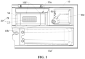
FIG. 1 is a schematic structural diagram of a dispenser assembly provided in an embodiment of the application. -
FIG. 2 is a schematic structural diagram of a dispenser provided in an embodiment of the application. -
FIG. 3 is a schematic cross-section view of the structure shown inFIG. 2 . -
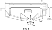
FIG. 4 is a schematic structural diagram of a detergent box provided in an embodiment of the application. -
FIG. 5 is a schematic cross-section view of the structure shown inFIG. 4 . -
FIG. 6 is a schematic structural diagram of a water treatment device provided in an embodiment of the application. -
FIG. 7 is a schematic exploded view of the structure shown inFIG. 6 . -
FIG. 8 is a schematic structural diagram of a bracket and elastic bodies provided in an embodiment of the application. - It should be noted that embodiments of the application and technical features in the embodiments may be combined with each other without conflict. Detailed descriptions in specific implementations should be understood as an explanation and description of the purpose of the application, and should not be considered as undue limitation of the application.
- In the embodiments of the application, orientation or position relationships such as "up", "down", "top", "bottom", "front", "rear", "left" and "right" are based on orientation or position relationships shown in
FIG. 2 andFIG. 5 . It should be understood that these orientation terms are only intended to facilitate describing the application and simplify descriptions, and are not intended to indicate or imply that the referred device or component must have a specific orientation, or must be configured and operate in a specific orientation, and thus cannot be understood as limitation of the application. The application will be further described in detail below with reference to the drawings and specific embodiments. - With reference to
FIG. 1 to FIG. 7 , an embodiment of the application provides a dispenser assembly, the dispenser assembly includes adispenser 10 and awater treatment device 20. Thedispenser 10 is formed with areplacement opening 10a, aplacement groove 10b and a liquid discharge opening 10c, both the replacement opening 10a and the liquid discharge opening 10c are communicated with theplacement groove 10b. Thewater treatment device 20 is detachably arranged in theplacement groove 10b, and is formed with awater inlet 20a, awater outlet 20b, and areagent cavity 20c configured to receive a water treatment agent, both the water inlet 20a and thewater outlet 20b are communicated with thereagent cavity 20c, and thewater outlet 20b is communicated with theplacement groove 10b. - In the dispenser assembly provided in the embodiment of the application, water may enter the
reagent cavity 20c through thewater inlet 20a, treated water obtained after it is treated by the water treatment agent enters theplacement groove 10b through thewater outlet 20b, and the treated water in theplacement groove 10b is discharged out of thedispenser 10 through the liquid discharge opening 10c. On one hand, thedispenser 10 is configured to dispense clothing treatment reagents such as detergent or the like, thedispenser 10 is an accessory of a detergent box, and an installation position is provided for thewater treatment device 20 by using thedispenser 10, so that manufacturing cost is low, and the user may easily replace and/or maintain thewater treatment device 20. On the other hand, thewater treatment device 20 may be taken out from theplacement groove 10b or put into theplacement groove 10b through the replacement opening 10a, that is, thewater treatment device 20 is replaced by using thereplacement opening 10a. The user may replacewater treatment devices 20 with different functions according to requirements, which is easy to operate and provides a good user experience. - The water treatment agent refers to a reagent which may change compositions of water. Types of the water treatment agent are not limited. Exemplarily, the water treatment agent includes, but is not limited to a scale inhibitor, a bactericide, and/or an aromatherapy agent, etc.
- Exemplarily, the scale inhibitor refers to a reagent which may disperse, interfere or prevent generation of insoluble inorganic salt. Hardness of the water is reduced by the scale inhibitor, to improve washing effects. The scale inhibitor may be a solid substance, and may be slowly dissolved and released when it is exposed to water. For example, the scale inhibitor is in a shape of granules. Modes of reducing hardness of the water by the scale inhibitor are not limited. Mechanisms of reducing hardness of the water by the scale inhibitor include, but are not limited to chelation and solubilization, agglomeration and dispersion, electrostatic repulsion, or crystal distortion, etc.
- Exemplarily, the bactericide refers to a reagent which may inhibit growth of bacteria or eliminate bacteria. The bactericide includes, but is not limited to a silver ion bactericide, etc.
- Exemplarily, the aromatherapy agent refers to a reagent which may release an aromatic substance. In this way, fragrance may be added to clothes.
- The
dispenser 10 is used in a detergent box of a clothing treatment machine. With reference toFIG. 4 to FIG. 7 , the detergent box provided in an embodiment of the application includes abox body 40 and the dispenser assembly in any one of the embodiments of the application. Thebox body 40 is formed with awater injection channel 40a, aliquid discharge channel 40b and anopening groove 40c. Thedispenser 10 is configured to draw out from theopening groove 40c or push into theopening groove 40c through an opening of theopening groove 40c, thewater injection channel 40a is configured to inject water into thewater inlet 20a, and theliquid discharge channel 40b is communicated with theliquid discharge opening 10c. - In the detergent box provided in the embodiment of the application, the
dispenser 10 is movably arranged in thebox body 40, so that when it needs to replace and/or maintain thewater treatment device 20, thedispenser 10 is drawn out of theopening groove 40c through the opening of theopening groove 40c, and thus thewater treatment device 20 may be taken out through thereplacement opening 10a. After replacement and/or maintenance is completed, thedispenser 10 is pushed into theopening groove 40c, and both thedispenser 10 and thewater treatment device 20 are hidden in thebox body 40. In a state where both thewater treatment device 20 and thedispenser 10 are located in theopening groove 40c, thewater injection channel 40a may inject water into thewater inlet 20a, so that the water enters thereagent cavity 20c and comes into contact with the water treatment agent, and the treated water enters theliquid discharge channel 40b through theliquid discharge opening 10c. - In an embodiment, with reference to
FIG. 5 to FIG. 7 , thewater treatment device 20 includes ahousing 21 and a holdingshell 22, thehousing 21 is formed with thewater inlet 20a, thewater outlet 20b and a water-passage cavity 21a, both thewater inlet 20a and thewater outlet 20b are communicated with the water-passage cavity 21a, the holdingshell 22 is arranged in the water-passage cavity 21a and is formed with thereagent cavity 20c andmultiple filter holes 22a, and thefilter holes 22a are communicated with the water-passage cavity 21a and thereagent cavity 20c. The filter holes 22a are configured to implement circulation of water between the water-passage cavity 21a and thereagent cavity 20c. The water in the water-passage cavity 21a enter thereagent cavity 20c through thefilter holes 22a, to come into contact with the water treatment agent, and the treated water flows out of thereagent cavity 20c through thefilter holes 22a, to be discharged into theopening groove 40c through thewater outlet 20b. The water treatment agent is constrained by the holdingshell 22, to prevent the water treatment agent from entering the water-passage cavity 21a. The water-passage cavity 21a provides a certain buffer space for the water, which increases time for the water to come into contact with the water treatment agent, so that the water may fully react with the water treatment agent. - The water treatment agent may be a solid substance, and may be slowly dissolved and released when it is exposed to water. For example, the water treatment agent is in a shape of granules, and the water treatment agent has a volume greater than size of the
filter hole 22a, to prevent the water treatment agent from going out of the holdingshell 22 through thefilter holes 22a. The water treatment agent is constrained in the holdingshell 22, and does not block thewater inlet 20a and/or thewater outlet 20b substantially, thereby keeping water passage unblocked. - In an embodiment, the holding
shell 22 is detachably connected to thehousing 21. In this way, the holdingshell 22 is prevented from moving arbitrarily in thehousing 21. - Exemplarily, in an embodiment, an end in a length direction of the holding
shell 22 is plugged into thehousing 21, and an end in the length direction of the holdingshell 22 is snap-fitted with thehousing 21. In this way, it not only facilitates positioning and assembly of the holdingshell 22 and thehousing 21, but also it may enhance structural strength of the holdingshell 22, to prevent the holdingshell 22 from bending and deforming with an impact of water flow. - Shapes of the holding
shell 22 are not limited. Exemplarily, with reference toFIG. 6 and FIG. 7 , the shape of the holdingshell 22 is substantially a cylindrical shape. - Shapes of the
housing 21 are not limited. Exemplarily, with reference toFIG. 6 , the shape of thehousing 21 is substantially a hexahedral shape. - Specific structures of the
housing 21 are not limited. Exemplarily, with reference toFIG. 6 and FIG. 7 , thehousing 21 includes ashell 211 and two end covers 212. Theshell 211 is provided with openings at two ends in a length direction thereof. The twoend covers 212 detachably cover the openings at two ends in the length direction of theshell 211 respectively, to define the water-passage cavity 21a together. Both thewater inlet 20a and thewater outlet 20b are formed on theshell 211. In this way, it facilitates quickly assembling the holdingshell 22 into thehousing 21, and it may also easily disassemble the holdingshell 22. The user may also replace the holdingshell 22 while reuse thehousing 21, so that cost is low. - Exemplarily, in an embodiment, with reference to
FIG. 7 , one of the end covers 212 is snap-fitted with theshell 211, and another one of the end covers 212 is threadedly connected to theshell 211. In this way, it facilitates assembling the end covers 212 and theshell 21 more stably. - In an embodiment, the
housing 21 is formed with overflow openings communicated with the water-passage cavity 21a. Exemplarily, one of the end covers 212 is formed with the overflow openings. The overflow openings improve water outlet capacity of thehousing 21, speed up water discharge, and prevent the water in the water-passage cavity 21a from flowing back to thewater inlet 20a to a certain extent. - Specific structures of the holding
shell 22 are not limited. Exemplarily, in an embodiment, with reference toFIG. 6 and FIG. 7 , the holdingshell 22 includes afilter shell 221 and twofixation sleeves 222. Thefilter shell 221 is provided with openings at two ends in a length direction thereof. The twofixation sleeves 222 detachably cover the openings at two ends in the length direction of thefilter shell 221 respectively, to define thereagent cavity 20c together. The filter holes 22a are formed in a circumferential surface of thefilter shell 221. In this way, it not only facilitates quickly dispensing the water treatment agent into the holdingshell 22, but also it may enhance structural strength of thefilter shell 221 through thefixation sleeves 222, to prevent the water flow from impacting thefilter shell 221 and making thefilter shell 221 bent and deformed. - In an embodiment, with reference to
FIG. 1 andFIG. 2 , the dispenser assembly includeselastic bodies 30, theelastic bodies 30 are arranged on at least one side surface of theplacement groove 10b and abut against thewater treatment device 20 tightly. For example, theelastic bodies 30 abut against thehousing 21 tightly. Elastic force of theelastic bodies 30 press against thewater treatment device 20, and elastic deformation force of theelastic bodies 30 may increase friction force between theelastic bodies 30 and thewater treatment device 20. In this way, it is difficult for thewater treatment device 20 to go out of theplacement groove 10b through thereplacement opening 10a. - Specific structures of the
elastic bodies 30 are not limited. Exemplarily, in an embodiment, with reference toFIG. 3 , theelastic bodies 30 are substantially in a structure of sheets. Theelastic bodies 30 have simple structures, are easy to manufacture, and have low cost. - In an embodiment, with reference to
FIG. 1 andFIG. 2 , theelastic bodies 30 are arranged on two opposite side surfaces of theplacement groove 10b, and two opposite side surfaces of thewater treatment device 20 abut against twoelastic bodies 30 respectively. Exemplarily, the twoelastic bodies 30 are located at two sides in a length direction of thehousing 21 respectively, and abut against two side surfaces in the length direction of thehousing 21 respectively. Thewater treatment device 20 is clamped between the twoelastic bodies 30, and has good stability. When it needs to disassemble thewater treatment device 20, the user may grip thewater treatment device 20 toward a side of one of theelastic bodies 30 with his/her hands, and push another one of theelastic bodies 30 to spread in a direction away from thewater treatment device 20, to quickly take out thewater treatment device 20. - In an embodiment, with reference to
FIG. 1 ,FIG. 3 andFIG. 5 , an end of theelastic body 30 is connected to thedispenser 10, another end of theelastic body 30 is a free end extending into theplacement groove 10b, and the free end is formed with arespective protrusion 31 abutting against thewater treatment device 20. Exemplarily,protrusions 31 are formed on side surfaces of respective free ends facing thehousing 21 and abut against thehousing 21. In this way, on one hand, theprotrusions 31 may effectively come into contact with thewater treatment device 20, and reduce scratches between thewater treatment device 20 and theelastic bodies 30. On the other hand, there are gaps between theelastic bodies 30 and thewater treatment device 20, so that the user's fingers may extend into the gaps to come into contact with a side surface of thewater treatment device 20 facing theelastic bodies 30, thereby applying force to thewater treatment device 20 to disassemble thewater treatment device 20. - Shapes of the
protrusions 31 are not limited. Exemplarily, with reference toFIG. 2 , theprotrusions 31 are substantially in a shape of strips. In this way, there are moderate contact areas between theprotrusions 31 and thehousing 21, so that both assembly stability and disassembly convenience are taken into account. - In an embodiment, with reference to
FIG. 5 andFIG. 6 , a part of a side surface of thewater treatment device 20 facing theelastic bodies 30 is recessed to form agroove 20d, at least a part of therespective protrusion 31 is located in thegroove 20d, and therespective protrusion 31 abuts against a groove wall surface of thegroove 20d. Exemplarily, a part of a side surface of thehousing 21 facing theelastic bodies 30 is recessed to form thegroove 20d. On one hand, thegroove 20d may provide a hand-gripping position for the user, and the user's fingers come into contact with the groove wall surface of thegroove 20d, to apply force to grip and move thewater treatment device 20, and prevent the fingers from slipping off in a process of applying the force. On the other hand, the groove wall surface of thegroove 20d abuts againstprotrusions 31, to play a role of bearing thewater treatment device 20, and prevent thewater treatment device 20 from slipping off in case that it is touched by mistake. - In an embodiment, with reference to
FIG. 2 ,FIG. 3 ,FIG. 6 and FIG. 7 , thereplacement opening 10a is formed in an upper side surface of thedispenser 10, theliquid discharge opening 10c is formed in a rear side surface of thedispenser 10, thewater inlet 20a is formed in an upper side surface of thewater treatment device 20, thewater outlet 20b is formed in a lower side surface of thewater treatment device 20, and theelastic bodies 30 are arranged in a front side surface and/or a rear side surface of theplacement groove 10b. Exemplarily, thewater inlet 20a is formed in an upper side surface of thehousing 21, and thewater outlet 20b is formed in a lower side surface of thehousing 21. Water flowing through thewater treatment device 20 flows in from top and flows out from bottom, resistance thereof is small, which not only facilitates circulation of the water, but also drains the water in thewater treatment device 20 such as thehousing 21 as much as possible, to avoid residual water. The user may take or place thewater treatment device 20 from top through thereplacement opening 10a, which reduces the user's bending degree or hand raising height, and makes operations more comfortable. - Exemplarily, in some embodiments, the
elastic bodies 30 are arranged on the front side surface of theplacement groove 10b. In some other embodiments, theelastic bodies 30 are arranged on the rear side surface of theplacement groove 10b. In some other embodiments, with reference toFIG. 3 , theelastic bodies 30 are arranged on both the front side surface and the rear side surface of theplacement groove 10b. - Exemplarily, in an embodiment, with reference to
FIG. 5 , in a state where thewater treatment device 20 is assembled in theplacement groove 10b, lower surfaces ofprotrusions 31 abut against the groove wall surface of thegroove 20d. In this way, it needs to apply a large upward acting force to thewater treatment device 20, so that theprotrusions 31 go out of thegroove 20d to disassemble thewater treatment device 20, and thewater treatment device 20 may be assembled in thedispenser 10 more stably. - Exemplarily, in an embodiment, with reference to
FIG. 5 , the opening of theopening groove 40c is formed in a front side surface of thebox body 40. In this way, the user may draw out thedispenser 10 from front, and then take thewater treatment device 20 from top, which are convenient for operations. - It should be noted that "up" refers to a direction facing the ceiling, and "down" refers to a direction opposite to "up"; "front" refers to a direction facing the user, and "rear" refers to a direction opposite to "front".
- Exemplarily, in an embodiment, with reference to
FIG. 5 ,multiple spray holes 40a' are formed in a lower side surface of thewater injection channel 40a, and are located above thewater inlet 20a. Taking a plane perpendicular to an up-down direction as a projection surface, projections ofmultiple spray holes 40a' are in a range of projection of thewater inlet 20a. On one hand, thespray holes 40a' penetrate the lower side surface of thewater injection channel 40a, and are configured to spray the water from thewater injection channel 40a into thewater inlet 20a. The spray holes 40a' may have small diameters to disperse water flow, and the water flow is sprayed into thewater inlet 20a throughmultiple spray holes 40a' in a shower-like manner, which increases a contact area between the water flow and the water treatment agent. On the other hand, thewater inlet 20a has a large size, and area of thewater inlet 20a is greater than a sum of areas ofmultiple spray holes 40a', which facilitates thewater inlet 20a to receive water from thespray holes 40a'. - In an embodiment, with reference to
FIG. 1 ,convex ribs 10b' are formed on a left side surface and/or a right side surface of theplacement groove 10b, and abut against thewater treatment device 20. For example, theconvex ribs 10b' may be formed on the left side surface of theplacement groove 10b. For another example, theconvex ribs 10b' may be formed on the right side surface of theplacement groove 10b. For another example, with reference toFIG. 2 , theconvex ribs 10b' may be formed on the left side surface and the right side surface of theplacement groove 10b. Exemplarily, theconvex ribs 10b' abut against thehousing 21. In this way, theconvex ribs 10b' may effectively come into contact with thewater treatment device 20 such as thehousing 21, which may not only prevent thewater treatment device 20 from offsetting in theplacement groove 10b, to play a role of positioning and limiting, but also may reduce scratches between thewater treatment device 20 and side surfaces of theplacement groove 10b, to facilitate assembly and disassembly of thewater treatment device 20. - There may be one or multiple
convex ribs 10b' in number. "multiple" includes two and more than two. - Shapes of the
convex ribs 10b' are not limited. With reference toFIG. 1 , theconvex ribs 10b' may be in point-shaped structures with small sizes. - In an embodiment, with reference to
FIG. 2 andFIG. 5 , limitingribs 10b" are formed on a bottom side surface of theplacement groove 10b, and abut against thewater treatment device 20. Exemplarily, the limitingribs 10b" abut against a bottom surface of thehousing 21. In this way, a certain supportive force is provided by the limitingribs 10b" to thewater treatment device 20. There is an interval space between a bottom surface of thewater treatment device 20 such as the bottom surface of thehousing 21 and the bottom side surface of theplacement groove 10b, to prevent the bottom surface of thewater treatment device 20 such as the bottom surface of thehousing 21 from fitting the bottom side surface of theplacement groove 10b. The water flow from thewater outlet 20b may quickly flow to the liquid discharge opening 10c through the interval space. - It should be noted that "top" is consistent with an upper direction, and "bottom" is consistent with a lower direction.
- There may be one or multiple limiting
ribs 10b" in number. Shapes of the limitingribs 10b" are not limited. Exemplarily, with reference toFIG. 2 , the limitingribs 10b" include, but are not limited to strip-shaped or point-shaped structures, etc. - In an embodiment, with reference to
FIG. 2 andFIG. 5 , thedispenser 10 is formed with adetergent groove 10d communicated with theliquid discharge channel 40b, and thedetergent groove 10d is provided with an opening at an upper side thereof. The user may draw out thedispenser 10 from theopening groove 40c, and add detergent into thedetergent groove 10d through the opening at the upper side thereof. The detergent may enter a washing cavity of a washing drum through theliquid discharge channel 40b, to wash clothes. - In an embodiment, with reference to
FIG. 5 , thedispenser 10 is formed with asoftener groove 10e communicated with theliquid discharge channel 40b, and thesoftener groove 10e is provided with an opening at an upper side thereof. The user may draw out thedispenser 10 from theopening groove 40c, and add softener into thesoftener groove 10e through the opening at the upper side thereof. The softener may enter the washing cavity through theliquid discharge channel 40b, to brighten and soften clothes. - In an embodiment, the
dispenser 10 is formed with a siphon channel communicated with thesoftener groove 10e and theliquid discharge channel 40b. The softener is sent into theliquid discharge channel 40b through siphon effects of the siphon channel. - In an embodiment, a communication opening is formed in the rear side surface of the
dispenser 10, and is communicated with thedetergent groove 10d and theliquid discharge channel 40b. In this way, the detergent enters theliquid discharge channel 40b through the communication opening. - In an embodiment, with reference to
FIG. 2 , theplacement groove 10b and thesoftener groove 10e may be arranged at an interval in a front-rear direction. In this way, volumes of both theplacement groove 10b and thesoftener groove 10e may be large without increasing size of thedispenser 10. - In an embodiment, with reference to
FIG. 3 andFIG. 8 , thedispenser 10 includes abase 11 and abracket 12. Thebase 11 is formed with an open slot, the open slot is provided with an upper opening, and theliquid discharge opening 10c is formed in a rear side surface of the open slot. Thebracket 12 is arranged at the upper opening of the open slot to define theplacement groove 10b, and is formed with thereplacement opening 10a, theelastic bodies 30 extend from the replacement opening 10a into theplacement groove 10b, two elastic bodies of theelastic bodies 30 are arranged at an interval in a front-rear direction, and thewater treatment device 20 is clamped between the twoelastic bodies 30. In this way, thewater treatment device 20 is tightly clamped between the twoelastic bodies 30 and has good stability. When it needs to assemble thewater treatment device 20, thewater treatment device 20 is pressed downward at thereplacement opening 10a until thewater treatment device 20 is clamped between the twoelastic bodies 30, so that assembly of thewater treatment device 20 is achieved quickly. When it needs to disassemble thewater treatment device 20, the user may grip thewater treatment device 20 toward a side of one of theelastic bodies 30 with his/her hands, and push another one of theelastic bodies 30 to spread in a direction away from thewater treatment device 20. For example, the user may grip a front side surface of thewater treatment device 20 with his/her hands, and push theelastic bodies 30 located at the rear to spread backward, to quickly take out thewater treatment device 20. - In an embodiment, with reference to
FIG. 3 andFIG. 8 , thebracket 12 is detachably connected to thebase 11, and thebracket 12 and theelastic bodies 30 are in an integrally formed structure. Thebase 11 and thebracket 12 may be structures independent of each other. That is, thebase 11 and thebracket 12 may be manufactured separately and individually. In this way, design and production difficulty of thebracket 12 and the base 11 may be reduced, to improve production efficiency. Thebracket 12 and theelastic bodies 30 are in an integrally formed structure, which may reduce assembly operations between thebracket 12 and theelastic bodies 30, and may also enhance structural strength of thebracket 12 and theelastic bodies 30. - Detachable connection between the
bracket 12 and thebase 11 includes, but is not limited to snap connection, screw connection or bolt connection, etc. - Exemplarily, in an embodiment, with reference to
FIG. 3 andFIG. 8 , thebracket 12 is formed with aclamping platform 121 and aclamping column 122 provided with abump 1221, and thebase 11 is formed with a clamping hole 111 and aflange 112. Theclamping column 122 may penetrate into the clamping hole 111 in a recoverable deformation manner, so that thebump 1221 moves from being above theclamping hole 122 to being below theclamping hole 122 and abuts against a lower surface of theclamping hole 122. Theclamping platform 121 may move from being above theflange 112 to being below theflange 112 in a recoverable deformation manner, so that theclamping platform 121 abuts against a lower surface of theflange 112. During assembly, an operator may press thebracket 12 downward, thebracket 12 is subject to a downward pressing force, theclamping column 122 may penetrate into the clamping hole 111 in a recoverable deformation manner, theclamping platform 121 may move from being above theflange 112 to being below theflange 112 in a recoverable deformation manner, thebump 1221 abuts against the lower surface of the clamping hole 111, and theclamping platform 121 abuts against the lower surface of theflange 112, to achieve snap connection between thebracket 12 and thebase 11. In this way, thebracket 12 is arranged at the upper opening of the open slot. That is, theclamping column 122 may be elastically deformed, so that thebump 1221 avoids the clamping hole 111, and thebump 1221 may move from being above the clamping hole 111 to being below the clamping hole 111. Theclamping platform 121 is provided with a portion which may be elastically deformed, so that it may move from being above theflange 112 to being below theflange 112. - In an embodiment, with reference to
FIG. 3 andFIG. 8 ,convex ribs 10b' are formed on a right side surface of thebracket 12,convex ribs 10b' are formed on a lift side surface of the open slot, and limitingribs 10b" are formed on a bottom side surface of the open slot. - In an embodiment, with reference to
FIG. 3 andFIG. 8 , thebase 11 is formed with thesoftener groove 10e, and thebracket 12 is formed with the siphon channel. Liquid in thesoftener groove 10e may be discharged into theliquid discharge channel 40b with siphon effects of the siphon channel. - In an embodiment, with reference to
FIG. 2 , theplacement groove 10b and thedetergent groove 10d may be arranged at an interval in a left-right direction. In this way, volumes of both theplacement groove 10b and thedetergent groove 10d may be large without increasing size of thedispenser 10 in the up-down direction. - It should be noted that the up-down direction, the front-rear direction and the left-right direction are perpendicular to each other and form a three-dimensional vertical coordinate system together.
- In an embodiment, the
detergent groove 10d is separated from theplacement groove 10b, and thebox body 40 is formed with a water supply channel communicated with thedetergent groove 10d. After water from the water supply channel enters thedetergent groove 10d, the water flushes the detergent into theliquid discharge channel 40b. - The water supply channel and the
water injection channel 40a may be separately controlled respectively for water entry, to implement multiple liquid entry modes and enrich functions of the clothing treatment machine. Exemplarily, in some embodiments, the water supply channel may be controlled to implement water entry separately, so that the detergent may be separately sent into the washing cavity. In some other embodiments, thewater injection channel 40a may be controlled to implement water entry separately, so that the treated water may be separately sent into the washing cavity. In some other embodiments, thewater injection channel 40a and the water supply channel may be controlled to implement water entry synchronously, so that the treated water and detergent may be premixed in theliquid discharge channel 40b and then sent into the washing cavity. - In some embodiments, the
opening groove 40c may also be communicated with thedetergent groove 10d. In this way, the water flow in theopening groove 40c is used to flush the detergent in thedetergent groove 10d into theliquid discharge channel 40b. - A clothing treatment machine provided in an embodiment of the application includes a washing drum and the detergent box in any one of the embodiments of the application. The washing drum is formed with a washing cavity. The
liquid discharge channel 40b is communicated with the washing cavity. - In the clothing treatment machine provided in the embodiment of the application, the
water treatment device 20 provides treated water for the washing cavity, and clothes are washed through the treated water, to improve clothing treatment effects. For example, a clothing treatment agent may be a scale inhibitor, hardness of water is reduced by the scale inhibitor, to form softened water, to prevent clothes from turning yellow and becoming stiff. - In an embodiment, the
water injection channel 40a may be connected to a water inlet valve of the clothing treatment machine, and the water inlet valve is connected to a tap water pipe. In this way, the tap water enters thewater treatment device 20 through thewater injection channel 40a, to react with the water treatment agent, and then the treated water is discharged into the washing cavity through theliquid discharge channel 40b. - In an embodiment, the washing drum is rotatable. In this way, movement of the clothes and water flow may be driven by rotation of the washing drum, to wash the clothes. For example, cleaning, rinsing, dehydration or the like of the clothes may be implemented by rotation of the washing drum.
- In an embodiment, the clothing treatment machine may include a tub sleeved out of the washing drum. Through holes may be formed in a circumferential surface of the washing drum. The tub may be configured to hold water, and the water in the tub may enter the washing drum or flow out of the washing drum through the through holes. The tub may be kept fixed, which facilitates arrangement of the water inlet valve, the
box body 40 or other structures on the tub, to reduce assembly difficulty. - In an embodiment, a rotation axis of the washing drum may be in a horizontal direction. In other words, the clothing treatment machine may be a drum-type clothing treatment machine. Exemplarily, an axis of the tub and the rotation axis of the washing drum are in the horizontal direction, and both the washing drum and the tub are opened toward their front sides. In this way, the user may put clothes into the washing cavity or take clothes out of the washing cavity through openings at the front sides of the washing drum and the tub.
- In an embodiment, the clothing treatment machine includes a casing, and both the washing drum and the
box body 40 are arranged in the casing. The casing is formed with a drawing-pulling opening, and the opening of theopening groove 40c faces the drawing-pulling opening. Thedispenser 10 may be drawn out of the casing or pushed into the casing through the drawing-pulling opening. Thedispenser 10 is drawn out of the casing from the drawing-pulling opening, so that the user may add detergent into thedispenser 10 or replace thewater treatment device 20. After processing is completed, thedispenser 10 is pushed into the casing. The casing may prevent the user or other objects from touching thedispenser 10 and thewater treatment device 20 by mistake, which has high safety and good aesthetics. - In an embodiment, the drawing-pulling opening may be formed at an upper left corner or upper right corner of a front side surface of the casing. In this way, the drawing-pulling opening faces the user and is at a high height, and the user may draw and pull the
dispenser 10 with his/her hands by bending down slightly or without bending down, to assemble and disassemble thewater treatment device 20, which facilitates operations. - In an embodiment, the clothing treatment machine may also be provided with a drying function, that is, the clothing treatment machine may also be provided with a drying air duct communicated with the washing cavity. The drying air duct may supply airflow into the washing cavity, to dry clothes in the washing cavity.
- The above descriptions are only specific implementations of the application, however, the scope of protection of the application is not limited thereto. Variation or replacement easily conceived by any technician familiar with this technical field within the technical scope disclosed in the application, should fall within the scope of protection of the application. Therefore, the scope of protection of the application should be subject to the scope of protection of the claims.
Claims (12)
- A dispenser assembly, comprising:a dispenser, formed with a replacement opening, a placement groove and a liquid discharge opening, both the replacement opening and the liquid discharge opening communicated with the placement groove; anda water treatment device, detachably arranged in the placement groove, and formed with a water inlet, a water outlet, and a reagent cavity receiving a water treatment agent, both the water inlet and the water outlet communicated with the reagent cavity, and the water outlet communicated with the placement groove.
- The dispenser assembly of claim 1, comprising: elastic bodies, arranged on at least one side surface of the placement groove and abutting against the water treatment device tightly.
- The dispenser assembly of claim 2, wherein an end of the elastic body is connected to the dispenser, another end of the elastic body is a free end extending into the placement groove, and the free end is formed with a protrusion abutting against the water treatment device.
- The dispenser assembly of claim 3, wherein a part of a side surface of the water treatment device facing the elastic bodies is recessed to form a groove, at least a part of the protrusion is located in the groove, and the protrusion abuts against a groove wall surface of the groove.
- The dispenser assembly of claim 2, wherein the replacement opening is formed in an upper side surface of the dispenser, the liquid discharge opening is formed in a rear side surface of the dispenser, the water inlet is formed in an upper side surface of the water treatment device, the water outlet is formed in a lower side surface of the water treatment device, and the elastic bodies are arranged in a front side surface and/or a rear side surface of the placement groove.
- The dispenser assembly of claim 5, wherein convex ribs are formed on a left side surface and/or a right side surface of the placement groove, and abut against the water treatment device.
- The dispenser assembly of claim 5, wherein limiting ribs are formed on a bottom side surface of the placement groove, and abut against the water treatment device.
- The dispenser assembly of claim 2, wherein the dispenser comprises:a base, formed with an open slot, the open slot provided with an upper opening, and the liquid discharge opening formed in a rear side surface of the open slot; anda bracket, arranged at the upper opening of the open slot to define the placement groove, and formed with the replacement opening, the elastic bodies extending from the replacement opening into the placement groove, two elastic bodies of the elastic bodies arranged at an interval in a front-rear direction, and the water treatment device clamped between the two elastic bodies.
- The dispenser assembly of claim 8, wherein the bracket is detachably connected to the base, and the bracket and the elastic bodies are in an integrally formed structure.
- The dispenser assembly of any one of claims 1 to 9, wherein the water treatment device comprises a housing and a holding shell, the housing is formed with the water inlet, the water outlet and a water-passage cavity, both the water inlet and the water outlet are communicated with the water-passage cavity, the holding shell is arranged in the water-passage cavity and is formed with the reagent cavity and a plurality of filter holes, and the plurality of filter holes are communicated with the water-passage cavity and the reagent cavity.
- A detergent box, comprising:a box body, formed with a water injection channel, a liquid discharge channel and an opening groove; anda dispenser assembly of any one of claims 1 to 10, a dispenser being able to draw out from the opening groove or push into the opening groove through an opening of the opening groove, the water injection channel being able to inject water into a water inlet, and the liquid discharge channel communicated with a liquid discharge opening.
- A clothing treatment machine, comprising:a washing drum, formed with a washing cavity; anda detergent box of claim 11, a liquid discharge channel communicated with the washing cavity.
Applications Claiming Priority (2)
| Application Number | Priority Date | Filing Date | Title |
|---|---|---|---|
| CN202210337065.XA CN114703634B (en) | 2022-03-31 | 2022-03-31 | Distribution box assembly, detergent box and clothes treating machine |
| PCT/CN2022/108636 WO2023184805A1 (en) | 2022-03-31 | 2022-07-28 | Dispenser assembly, detergent box and clothing treatment machine |
Publications (2)
| Publication Number | Publication Date |
|---|---|
| EP4491790A1 true EP4491790A1 (en) | 2025-01-15 |
| EP4491790A4 EP4491790A4 (en) | 2025-05-07 |
Family
ID=82170637
Family Applications (1)
| Application Number | Title | Priority Date | Filing Date |
|---|---|---|---|
| EP22934626.7A Pending EP4491790A4 (en) | 2022-03-31 | 2022-07-28 | Dispenser assembly, detergent box and clothing treatment machine |
Country Status (4)
| Country | Link |
|---|---|
| EP (1) | EP4491790A4 (en) |
| JP (1) | JP2025510802A (en) |
| CN (1) | CN114703634B (en) |
| WO (1) | WO2023184805A1 (en) |
Families Citing this family (3)
| Publication number | Priority date | Publication date | Assignee | Title |
|---|---|---|---|---|
| WO2023184695A1 (en) * | 2022-03-31 | 2023-10-05 | 合肥美的洗衣机有限公司 | Detergent box assembly and washing apparatus |
| CN114703634B (en) * | 2022-03-31 | 2023-11-24 | 无锡小天鹅电器有限公司 | Distribution box assembly, detergent box and clothes treating machine |
| WO2023184694A1 (en) * | 2022-03-31 | 2023-10-05 | 合肥美的洗衣机有限公司 | Scale prevention module, dispenser, and washing machine |
Family Cites Families (23)
| Publication number | Priority date | Publication date | Assignee | Title |
|---|---|---|---|---|
| DE3715832A1 (en) * | 1987-05-12 | 1988-11-24 | Bosch Siemens Hausgeraete | DETERGENT DISCHARGE TRAY WITH AUXILIARY DEVICE FOR LIQUID DETERGENT |
| JP3757457B2 (en) * | 1996-02-27 | 2006-03-22 | 松下電器産業株式会社 | Washing machine |
| KR19990076567A (en) * | 1998-03-04 | 1999-10-15 | 윤종용 | Washing machines with devices for magnetizing water supplied to detergent containers |
| JP2002331196A (en) * | 2001-05-09 | 2002-11-19 | Toshiba Corp | Washing machine |
| KR101203552B1 (en) * | 2005-06-29 | 2012-11-21 | 엘지전자 주식회사 | Detergent applying apparatus of cleaning device |
| DE102008004258B4 (en) * | 2007-03-26 | 2018-06-28 | BSH Hausgeräte GmbH | Household washing machine with a Einspüleinrichtung |
| US8397328B2 (en) * | 2008-07-01 | 2013-03-19 | Whirlpool Corporation | Apparatus and method for controlling concentration of wash aid in wash liquid |
| EP2679716A1 (en) * | 2012-06-29 | 2014-01-01 | Electrolux Home Products Corporation N.V. | Laundry washing machine |
| CN105624990B (en) * | 2014-10-30 | 2020-02-14 | 青岛海尔智能技术研发有限公司 | Filter equipment and washing machine |
| CN204849390U (en) * | 2015-06-24 | 2015-12-09 | 松下家电研究开发(杭州)有限公司 | Washing machine's detergent box and washing machine |
| CN108570827A (en) * | 2017-03-14 | 2018-09-25 | 青岛海尔滚筒洗衣机有限公司 | A kind of detergent box and washing machine of washing machine |
| WO2018192460A1 (en) * | 2017-04-17 | 2018-10-25 | 青岛海尔滚筒洗衣机有限公司 | Automatic dispensing system for washing, and washing machine |
| CN109385842B (en) * | 2017-08-11 | 2022-04-26 | 青岛海尔洗衣机有限公司 | Washing machine |
| EP3473764B1 (en) * | 2017-10-18 | 2020-08-12 | Electrolux Laundry Systems Sweden AB | Washing machine detergent dispenser |
| CN208701357U (en) * | 2018-07-05 | 2019-04-05 | 青岛海尔滚筒洗衣机有限公司 | Clothes treatment device |
| CN110685128B (en) * | 2018-07-05 | 2024-06-25 | 无锡小天鹅电器有限公司 | Base assembly and clothes treatment device with same |
| CN109944027B (en) * | 2019-02-28 | 2022-02-01 | 无锡小天鹅电器有限公司 | Clothes treating apparatus |
| JP7498600B2 (en) * | 2020-06-17 | 2024-06-12 | 東芝ライフスタイル株式会社 | Clothes Processing Equipment |
| CN214736785U (en) * | 2020-12-24 | 2021-11-16 | 云米互联科技(广东)有限公司 | A scale inhibitory structure for a detergent box, a detergent box, and a washing machine |
| CN112726137B (en) * | 2020-12-24 | 2023-04-14 | 云米互联科技(广东)有限公司 | Detergent box cover with built-in scale inhibitor, detergent box, washing machine |
| JP2021065732A (en) * | 2021-02-02 | 2021-04-30 | アイリスオーヤマ株式会社 | Washing machine |
| CN215758108U (en) * | 2021-04-29 | 2022-02-08 | 青岛海高设计制造有限公司 | Detergent Box and Washing Machine |
| CN114703634B (en) * | 2022-03-31 | 2023-11-24 | 无锡小天鹅电器有限公司 | Distribution box assembly, detergent box and clothes treating machine |
-
2022
- 2022-03-31 CN CN202210337065.XA patent/CN114703634B/en active Active
- 2022-07-28 WO PCT/CN2022/108636 patent/WO2023184805A1/en not_active Ceased
- 2022-07-28 JP JP2024556541A patent/JP2025510802A/en active Pending
- 2022-07-28 EP EP22934626.7A patent/EP4491790A4/en active Pending
Also Published As
| Publication number | Publication date |
|---|---|
| JP2025510802A (en) | 2025-04-15 |
| CN114703634A (en) | 2022-07-05 |
| WO2023184805A1 (en) | 2023-10-05 |
| CN114703634B (en) | 2023-11-24 |
| EP4491790A4 (en) | 2025-05-07 |
Similar Documents
| Publication | Publication Date | Title |
|---|---|---|
| CN114703634B (en) | Distribution box assembly, detergent box and clothes treating machine | |
| CN102965884B (en) | front load washing machine | |
| CN108729135B (en) | A washing machine automatic delivery system and washing machine | |
| CN108729132B (en) | A washing machine automatic delivery system and washing machine | |
| EP4491789A1 (en) | Detergent box assembly and washing apparatus | |
| CN217127799U (en) | Lotion box subassembly and washing equipment | |
| US20120103028A1 (en) | Washing machine and detergent case thereof | |
| CN109944027B (en) | Clothes treating apparatus | |
| US7426932B2 (en) | Spray fill device and method for using the same | |
| KR20070040612A (en) | Detergent box in washing machine | |
| CN107893315A (en) | Feeding box and washing machine | |
| CN109881443B (en) | Clothes treating apparatus | |
| JP7838109B2 (en) | Input device and garment processing device | |
| CN116837603B (en) | Dispensing device and clothing processing equipment | |
| JP7704381B2 (en) | Dispenser box, detergent dispenser, washing machine unit, washing machine unit set | |
| CN112760941A (en) | Feeding device and clothes treatment equipment | |
| JP7329732B2 (en) | Auxiliary unit and washing machine | |
| CN109944026B (en) | Clothes treating apparatus | |
| CN212611508U (en) | Clothes treating agent feeding device and clothes treating equipment | |
| US20190226253A1 (en) | Garment processing device | |
| KR101034194B1 (en) | Washing machine with detergent supply | |
| KR101144792B1 (en) | Detergent box of washer | |
| CN116837600A (en) | Throwing device and clothes treatment equipment | |
| CN215856831U (en) | Workstation subassembly and laundry equipment | |
| CN111691136B (en) | Clothes treating apparatus |
Legal Events
| Date | Code | Title | Description |
|---|---|---|---|
| STAA | Information on the status of an ep patent application or granted ep patent |
Free format text: STATUS: THE INTERNATIONAL PUBLICATION HAS BEEN MADE |
|
| PUAI | Public reference made under article 153(3) epc to a published international application that has entered the european phase |
Free format text: ORIGINAL CODE: 0009012 |
|
| STAA | Information on the status of an ep patent application or granted ep patent |
Free format text: STATUS: REQUEST FOR EXAMINATION WAS MADE |
|
| 17P | Request for examination filed |
Effective date: 20241010 |
|
| AK | Designated contracting states |
Kind code of ref document: A1 Designated state(s): AL AT BE BG CH CY CZ DE DK EE ES FI FR GB GR HR HU IE IS IT LI LT LU LV MC MK MT NL NO PL PT RO RS SE SI SK SM TR |
|
| A4 | Supplementary search report drawn up and despatched |
Effective date: 20250408 |
|
| RIC1 | Information provided on ipc code assigned before grant |
Ipc: D06F 39/06 20060101ALI20250402BHEP Ipc: D06F 39/02 20060101AFI20250402BHEP |
|
| DAV | Request for validation of the european patent (deleted) | ||
| DAX | Request for extension of the european patent (deleted) |