EP4491757A1 - Thermal spraying device and thermal spraying control method - Google Patents
Thermal spraying device and thermal spraying control method Download PDFInfo
- Publication number
- EP4491757A1 EP4491757A1 EP23766622.7A EP23766622A EP4491757A1 EP 4491757 A1 EP4491757 A1 EP 4491757A1 EP 23766622 A EP23766622 A EP 23766622A EP 4491757 A1 EP4491757 A1 EP 4491757A1
- Authority
- EP
- European Patent Office
- Prior art keywords
- thermal spraying
- temperature
- machine
- controller
- humidity
- Prior art date
- Legal status (The legal status is an assumption and is not a legal conclusion. Google has not performed a legal analysis and makes no representation as to the accuracy of the status listed.)
- Pending
Links
Images


Classifications
-
- C—CHEMISTRY; METALLURGY
- C23—COATING METALLIC MATERIAL; COATING MATERIAL WITH METALLIC MATERIAL; CHEMICAL SURFACE TREATMENT; DIFFUSION TREATMENT OF METALLIC MATERIAL; COATING BY VACUUM EVAPORATION, BY SPUTTERING, BY ION IMPLANTATION OR BY CHEMICAL VAPOUR DEPOSITION, IN GENERAL; INHIBITING CORROSION OF METALLIC MATERIAL OR INCRUSTATION IN GENERAL
- C23C—COATING METALLIC MATERIAL; COATING MATERIAL WITH METALLIC MATERIAL; SURFACE TREATMENT OF METALLIC MATERIAL BY DIFFUSION INTO THE SURFACE, BY CHEMICAL CONVERSION OR SUBSTITUTION; COATING BY VACUUM EVAPORATION, BY SPUTTERING, BY ION IMPLANTATION OR BY CHEMICAL VAPOUR DEPOSITION, IN GENERAL
- C23C4/00—Coating by spraying the coating material in the molten state, e.g. by flame, plasma or electric discharge
- C23C4/18—After-treatment
-
- B—PERFORMING OPERATIONS; TRANSPORTING
- B05—SPRAYING OR ATOMISING IN GENERAL; APPLYING FLUENT MATERIALS TO SURFACES, IN GENERAL
- B05B—SPRAYING APPARATUS; ATOMISING APPARATUS; NOZZLES
- B05B12/00—Arrangements for controlling delivery; Arrangements for controlling the spray area
- B05B12/08—Arrangements for controlling delivery; Arrangements for controlling the spray area responsive to condition of liquid or other fluent material to be discharged, of ambient medium or of target ; responsive to condition of spray devices or of supply means, e.g. pipes, pumps or their drive means
- B05B12/084—Arrangements for controlling delivery; Arrangements for controlling the spray area responsive to condition of liquid or other fluent material to be discharged, of ambient medium or of target ; responsive to condition of spray devices or of supply means, e.g. pipes, pumps or their drive means responsive to condition of liquid or other fluent material already sprayed on the target, e.g. coating thickness, weight or pattern
-
- B—PERFORMING OPERATIONS; TRANSPORTING
- B05—SPRAYING OR ATOMISING IN GENERAL; APPLYING FLUENT MATERIALS TO SURFACES, IN GENERAL
- B05B—SPRAYING APPARATUS; ATOMISING APPARATUS; NOZZLES
- B05B12/00—Arrangements for controlling delivery; Arrangements for controlling the spray area
- B05B12/08—Arrangements for controlling delivery; Arrangements for controlling the spray area responsive to condition of liquid or other fluent material to be discharged, of ambient medium or of target ; responsive to condition of spray devices or of supply means, e.g. pipes, pumps or their drive means
- B05B12/12—Arrangements for controlling delivery; Arrangements for controlling the spray area responsive to condition of liquid or other fluent material to be discharged, of ambient medium or of target ; responsive to condition of spray devices or of supply means, e.g. pipes, pumps or their drive means responsive to conditions of ambient medium or target, e.g. humidity, temperature position or movement of the target relative to the spray apparatus
-
- B—PERFORMING OPERATIONS; TRANSPORTING
- B05—SPRAYING OR ATOMISING IN GENERAL; APPLYING FLUENT MATERIALS TO SURFACES, IN GENERAL
- B05B—SPRAYING APPARATUS; ATOMISING APPARATUS; NOZZLES
- B05B13/00—Machines or plants for applying liquids or other fluent materials to surfaces of objects or other work by spraying, not covered by groups B05B1/00 - B05B11/00
- B05B13/02—Means for supporting work; Arrangement or mounting of spray heads; Adaptation or arrangement of means for feeding work
- B05B13/0221—Means for supporting work; Arrangement or mounting of spray heads; Adaptation or arrangement of means for feeding work characterised by the means for moving or conveying the objects or other work, e.g. conveyor belts
- B05B13/0228—Means for supporting work; Arrangement or mounting of spray heads; Adaptation or arrangement of means for feeding work characterised by the means for moving or conveying the objects or other work, e.g. conveyor belts the movement of the objects being rotative
-
- B—PERFORMING OPERATIONS; TRANSPORTING
- B05—SPRAYING OR ATOMISING IN GENERAL; APPLYING FLUENT MATERIALS TO SURFACES, IN GENERAL
- B05B—SPRAYING APPARATUS; ATOMISING APPARATUS; NOZZLES
- B05B13/00—Machines or plants for applying liquids or other fluent materials to surfaces of objects or other work by spraying, not covered by groups B05B1/00 - B05B11/00
- B05B13/02—Means for supporting work; Arrangement or mounting of spray heads; Adaptation or arrangement of means for feeding work
- B05B13/04—Means for supporting work; Arrangement or mounting of spray heads; Adaptation or arrangement of means for feeding work the spray heads being moved during spraying operation
- B05B13/0431—Means for supporting work; Arrangement or mounting of spray heads; Adaptation or arrangement of means for feeding work the spray heads being moved during spraying operation with spray heads moved by robots or articulated arms, e.g. for applying liquid or other fluent material to three-dimensional [3D] surfaces
-
- B—PERFORMING OPERATIONS; TRANSPORTING
- B05—SPRAYING OR ATOMISING IN GENERAL; APPLYING FLUENT MATERIALS TO SURFACES, IN GENERAL
- B05B—SPRAYING APPARATUS; ATOMISING APPARATUS; NOZZLES
- B05B16/00—Spray booths
- B05B16/40—Construction elements specially adapted therefor, e.g. floors, walls or ceilings
-
- B—PERFORMING OPERATIONS; TRANSPORTING
- B05—SPRAYING OR ATOMISING IN GENERAL; APPLYING FLUENT MATERIALS TO SURFACES, IN GENERAL
- B05D—PROCESSES FOR APPLYING FLUENT MATERIALS TO SURFACES, IN GENERAL
- B05D3/00—Pretreatment of surfaces to which liquids or other fluent materials are to be applied; After-treatment of applied coatings, e.g. intermediate treating of an applied coating preparatory to subsequent applications of liquids or other fluent materials
- B05D3/08—Pretreatment of surfaces to which liquids or other fluent materials are to be applied; After-treatment of applied coatings, e.g. intermediate treating of an applied coating preparatory to subsequent applications of liquids or other fluent materials by flames
-
- C—CHEMISTRY; METALLURGY
- C23—COATING METALLIC MATERIAL; COATING MATERIAL WITH METALLIC MATERIAL; CHEMICAL SURFACE TREATMENT; DIFFUSION TREATMENT OF METALLIC MATERIAL; COATING BY VACUUM EVAPORATION, BY SPUTTERING, BY ION IMPLANTATION OR BY CHEMICAL VAPOUR DEPOSITION, IN GENERAL; INHIBITING CORROSION OF METALLIC MATERIAL OR INCRUSTATION IN GENERAL
- C23C—COATING METALLIC MATERIAL; COATING MATERIAL WITH METALLIC MATERIAL; SURFACE TREATMENT OF METALLIC MATERIAL BY DIFFUSION INTO THE SURFACE, BY CHEMICAL CONVERSION OR SUBSTITUTION; COATING BY VACUUM EVAPORATION, BY SPUTTERING, BY ION IMPLANTATION OR BY CHEMICAL VAPOUR DEPOSITION, IN GENERAL
- C23C4/00—Coating by spraying the coating material in the molten state, e.g. by flame, plasma or electric discharge
- C23C4/12—Coating by spraying the coating material in the molten state, e.g. by flame, plasma or electric discharge characterised by the method of spraying
-
- C—CHEMISTRY; METALLURGY
- C23—COATING METALLIC MATERIAL; COATING MATERIAL WITH METALLIC MATERIAL; CHEMICAL SURFACE TREATMENT; DIFFUSION TREATMENT OF METALLIC MATERIAL; COATING BY VACUUM EVAPORATION, BY SPUTTERING, BY ION IMPLANTATION OR BY CHEMICAL VAPOUR DEPOSITION, IN GENERAL; INHIBITING CORROSION OF METALLIC MATERIAL OR INCRUSTATION IN GENERAL
- C23C—COATING METALLIC MATERIAL; COATING MATERIAL WITH METALLIC MATERIAL; SURFACE TREATMENT OF METALLIC MATERIAL BY DIFFUSION INTO THE SURFACE, BY CHEMICAL CONVERSION OR SUBSTITUTION; COATING BY VACUUM EVAPORATION, BY SPUTTERING, BY ION IMPLANTATION OR BY CHEMICAL VAPOUR DEPOSITION, IN GENERAL
- C23C4/00—Coating by spraying the coating material in the molten state, e.g. by flame, plasma or electric discharge
- C23C4/12—Coating by spraying the coating material in the molten state, e.g. by flame, plasma or electric discharge characterised by the method of spraying
- C23C4/123—Spraying molten metal
-
- C—CHEMISTRY; METALLURGY
- C23—COATING METALLIC MATERIAL; COATING MATERIAL WITH METALLIC MATERIAL; CHEMICAL SURFACE TREATMENT; DIFFUSION TREATMENT OF METALLIC MATERIAL; COATING BY VACUUM EVAPORATION, BY SPUTTERING, BY ION IMPLANTATION OR BY CHEMICAL VAPOUR DEPOSITION, IN GENERAL; INHIBITING CORROSION OF METALLIC MATERIAL OR INCRUSTATION IN GENERAL
- C23C—COATING METALLIC MATERIAL; COATING MATERIAL WITH METALLIC MATERIAL; SURFACE TREATMENT OF METALLIC MATERIAL BY DIFFUSION INTO THE SURFACE, BY CHEMICAL CONVERSION OR SUBSTITUTION; COATING BY VACUUM EVAPORATION, BY SPUTTERING, BY ION IMPLANTATION OR BY CHEMICAL VAPOUR DEPOSITION, IN GENERAL
- C23C4/00—Coating by spraying the coating material in the molten state, e.g. by flame, plasma or electric discharge
- C23C4/12—Coating by spraying the coating material in the molten state, e.g. by flame, plasma or electric discharge characterised by the method of spraying
- C23C4/134—Plasma spraying
-
- B—PERFORMING OPERATIONS; TRANSPORTING
- B05—SPRAYING OR ATOMISING IN GENERAL; APPLYING FLUENT MATERIALS TO SURFACES, IN GENERAL
- B05B—SPRAYING APPARATUS; ATOMISING APPARATUS; NOZZLES
- B05B14/00—Arrangements for collecting, re-using or eliminating excess spraying material
- B05B14/40—Arrangements for collecting, re-using or eliminating excess spraying material for use in spray booths
-
- B—PERFORMING OPERATIONS; TRANSPORTING
- B05—SPRAYING OR ATOMISING IN GENERAL; APPLYING FLUENT MATERIALS TO SURFACES, IN GENERAL
- B05B—SPRAYING APPARATUS; ATOMISING APPARATUS; NOZZLES
- B05B7/00—Spraying apparatus for discharge of liquids or other fluent materials from two or more sources, e.g. of liquid and air, of powder and gas
- B05B7/16—Spraying apparatus for discharge of liquids or other fluent materials from two or more sources, e.g. of liquid and air, of powder and gas incorporating means for heating or cooling the material to be sprayed
- B05B7/20—Spraying apparatus for discharge of liquids or other fluent materials from two or more sources, e.g. of liquid and air, of powder and gas incorporating means for heating or cooling the material to be sprayed by flame or combustion
-
- B—PERFORMING OPERATIONS; TRANSPORTING
- B05—SPRAYING OR ATOMISING IN GENERAL; APPLYING FLUENT MATERIALS TO SURFACES, IN GENERAL
- B05B—SPRAYING APPARATUS; ATOMISING APPARATUS; NOZZLES
- B05B7/00—Spraying apparatus for discharge of liquids or other fluent materials from two or more sources, e.g. of liquid and air, of powder and gas
- B05B7/16—Spraying apparatus for discharge of liquids or other fluent materials from two or more sources, e.g. of liquid and air, of powder and gas incorporating means for heating or cooling the material to be sprayed
- B05B7/22—Spraying apparatus for discharge of liquids or other fluent materials from two or more sources, e.g. of liquid and air, of powder and gas incorporating means for heating or cooling the material to be sprayed electrically, magnetically or electromagnetically, e.g. by arc
- B05B7/222—Spraying apparatus for discharge of liquids or other fluent materials from two or more sources, e.g. of liquid and air, of powder and gas incorporating means for heating or cooling the material to be sprayed electrically, magnetically or electromagnetically, e.g. by arc using an arc
-
- B—PERFORMING OPERATIONS; TRANSPORTING
- B05—SPRAYING OR ATOMISING IN GENERAL; APPLYING FLUENT MATERIALS TO SURFACES, IN GENERAL
- B05D—PROCESSES FOR APPLYING FLUENT MATERIALS TO SURFACES, IN GENERAL
- B05D1/00—Processes for applying liquids or other fluent materials
- B05D1/02—Processes for applying liquids or other fluent materials performed by spraying
- B05D1/08—Flame spraying
Definitions
- An embodiment of the present disclosure relates to a thermal spraying device and a thermal spraying control method.
- a thermal spraying device in which a film forming material such as a metal or a ceramic is heated to be melted or brought into a state close to melting (semi-melting), and the film forming material that is melted or brought into the semi-melting state is sprayed onto a base material, thereby forming a film of the film forming material on the base material.
- Patent Document 1 Japanese Examined Utility Model Application Publication No. H5-29092
- a thermal spraying device including a thermal spraying torch that sprays a film forming material onto a base material
- peripheral devices including a robot that moves the thermal spraying torch, a rotary machine that fixes and rotates the base material, an air feeding device that controls temperature and humidity in a thermal spraying booth, one or more sensors including a thermo-hygrometer that detects temperature and humidity in the thermal spraying booth, an oxygen concentration meter that detects oxygen concentration, a radiation thermometer that detects temperature of a product, a cooling device that cools the product, a dust collecting device that collects dust generated in the thermal spraying booth, and the like are operated.
- the thermal spraying device and its peripheral devices had to be manually operated at the site by workers engaged in thermal spraying operation. Therefore, there is a problem that the thermal spraying operation becomes complicated and the operation efficiency is lowered. There was also a problem in the safety of workers at the site.
- An object of an embodiment of the present disclosure is to provide a thermal spraying device and a thermal spraying control method capable of reducing the complexity of a thermal spraying operation and improving the safety of the operation.
- a thermal spraying device includes a thermal spraying machine including a thermal spraying torch spraying a material onto a base material, one or more peripheral devices used with the thermal spraying machine, and a centralized control board enabling centralized operation of the thermal spraying machine and the one or more peripheral devices.
- a thermal spraying control method is a thermal spraying method performed by a thermal spraying machine, one or more peripheral devices used with the thermal spraying machine, and a centralized control board, the thermal spraying control method including collectively controlling the thermal spraying machine and the one or more peripheral devices using the centralized control board.
- thermo spraying device and a thermal spraying control method capable of reducing the complexity of a thermal spraying operation and improving the safety of the operation.
- a member or region is referred to as being "above (or below)" another member or region, this includes not only the case where it is directly above (or directly below) the other member or region, unless otherwise limited, but also the case where it is above (or below) the other member or region, that is, the case where another component is included between the other member or region.
- thermal spraying device 10 according to an embodiment of the present disclosure will be described with reference to the drawings.
- FIG. 1 is a diagram for explaining a configuration of the thermal spraying device 10 according to an embodiment of the present disclosure.
- the thermal spraying device 10 includes a centralized control board 101, a thermal spraying machine 103, and peripheral devices.
- the peripheral devices include a mover 105, a cooling gas feed machine 109, a rotary machine 113 including a workpiece (base material) 111, a first sensor 115, and a second sensor 117.
- the peripheral devices may include a temperature and humidity adjustment machine 121 and a dust collector 123.
- the thermal spraying machine 103 includes a thermal spraying torch 102, a thermal spraying control machine 106, a raw material feeder 107, and a gas feed machine 108.
- the thermal spraying machine 103 the mover 105, the cooling gas feed machine 109, the rotary machine 113, the first sensor 115, and the second sensor 117 are provided in a thermal spraying booth 119 in which a thermal spraying process is performed.
- the temperature and humidity adjustment machine 121 has an air duct 122 that connects into the thermal spraying booth 119.
- the dust collector 123 has an exhaust duct 124 connecting into the thermal spraying booth 119.
- the thermal spraying device 10 includes a safety door 125 that allows a worker W to enter and exit the inside and outside of the thermal spraying booth 119.
- the centralized control board 101 is installed outside the thermal spraying booth 119.
- the centralized control board 101 enables the respective components of the thermal spraying device 10 to be operated collectively. That is, the centralized control board 101 collectively controls operations of the thermal spraying machine 103, the mover 105, the cooling gas feed machine 109, the rotary machine 113, the first sensor 115, the second sensor 117, the temperature and humidity adjustment machine 121, and the dust collector 123.
- the centralized control board 101 receives an input operation by the worker W, controls the operation of each component of the thermal spraying device 10, and executes the thermal spraying process in the thermal spraying booth 119.
- the centralized control board 101 may control opening and closing of the safety door 125.
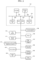
- FIG. 2 is a block diagram for explaining an example of a configuration of the centralized control board 101 according to the present embodiment.
- the centralized control board 101 may include a controller 201, a storage unit 203, an operation unit 205, a communication unit 207, and a display unit 209.
- the controller 201, the storage unit 203, the operation unit 205, the communication unit 207, and the display unit 209 are connected to each other by a bus 211.
- the controller 201 includes an arithmetic processor such as a CPU.
- the controller 201 executes a control program stored in the storage unit 203 by the CPU to control the operation of the thermal spraying device 10 to realize the thermal spraying process by the thermal spraying device 10.
- the controller 201 centrally controls the operations of the thermal spraying machine 103, the mover 105, the cooling gas feed machine 109, the rotary machine 113, the first sensor 115, the second sensor 117, the temperature and humidity adjustment machine 121, and the dust collector 123 constituting the thermal spraying device 10.
- the storage unit 203 is a storage device such as a ROM, a RAM or a hard disk.
- the storage unit 203 stores a control program for realizing the thermal spraying process by the thermal spraying device 10.
- the control program may be provided in a state of being stored in a computer-readable recording medium such as a magnetic recording medium, an optical recording medium, a magnetooptical recording medium, or a semiconductor memory.
- the centralized control board 101 may be provided with a device for reading a recording medium.
- the storage unit 203 may store settings of the thermal spraying machine 103, the mover 105, the cooling gas feed machine 109, the rotary machine 113, the first sensor 115, the second sensor 117, the temperature and humidity adjustment machine 121, and the dust collector 123, which constitute the thermal spraying device 10.
- the control program and the setting of each configuration of the thermal spraying device 10 may be downloaded via a network such as the Internet.
- the operation unit 205 is a device such as an operation panel, an operation button, and a touch panel, and outputs a signal corresponding to the input operation to the controller 201.
- the worker W engaged in the thermal spraying operation controls the operation of the thermal spraying device 10 via the operation unit 205.
- the worker W can instruct the start and stop of the thermal spraying process performed by the thermal spraying device 10 via the operation unit 205. Further, the worker W can appropriately change the settings of the thermal spraying machine 103, the mover 105, the cooling gas feed machine 109, the rotary machine 113, the first sensor 115, the second sensor 117, the temperature and humidity adjustment machine 121, the dust collector 123, and the like, which constitute the thermal spraying device 10 via the operation unit 205.
- the communication unit 207 performs communication with the respective components of the thermal spraying device 10, that is, the thermal spraying machine 103, the mover 105, the cooling gas feed machine 109, the rotary machine 113, the first sensor 115, the second sensor 117, the temperature and humidity adjustment machine 121, and the dust collector 123, based on the control of the controller 201.
- the communication may be wired communication or wireless communication.
- the function of the storage unit 203 may be realized by an external device that can communicate with the communication unit 207.
- the display unit 209 is a display device such as a liquid crystal display or an organic EL display. On the display unit 209, a screen based on the control by the controller 201 is displayed to the worker W based on the control by the controller 201. For example, the display unit 209 may display setting states and operating states of the thermal spraying machine 103, the mover 105, the cooling gas feed machine 109, the rotary machine 113, the first sensor 115, the second sensor 117, the temperature and humidity adjustment machine 121, and the dust collector 123, and detection results of the first sensor 115 and the second sensor 117.
- the thermal spraying machine 103 includes the spraying torch 102 coupled to the mover 105 described below.
- the thermal spraying torch 102 injects a thermal spray material supplied from the raw material feeder 107 and gas supplied from the gas feed machine 108 through the thermal spraying control machine 106.
- the thermal spraying by the thermal spraying machine 103 may be gas thermal spraying including flame spraying and high-speed flame spraying, and may be electric thermal spraying including arc spraying and plasma spraying.
- the thermal spraying torch 102 melts or semi-melts the thermal spray material by gas or electricity (arc or plasma) to generate thermal spray particles.
- the thermal spraying torch 102 accelerates the generated thermal spray particles by gas such as compressed air, and sprays the generated thermal spray particles onto the workpiece 111 of the rotary machine 113 to form a coating film of the thermal spray particles on a surface of the workpiece 111.
- the mover 105 moves the thermal spraying torch 102 based on the control of the controller 201.
- the mover 105 may be, for example, an industrial robot. Specifically, the mover 105 may be a six-axis or seven-axis vertical articulated robot.
- the mover 105 controls movements of the thermal spraying torch 102 in the front, rear, up, down, left, and right directions, an angle of the thermal spraying torch 102 relative to the surface of the workpiece 111 of the rotary machine 113, and the like, based on the control of the controller 201.
- the mover 105 may move the thermal spraying torch 102 so that the thermal spraying torch 102 approaches the workpiece 111 of the rotary machine 113, and tilt the thermal spraying torch 102 at a predetermined angle relative to the surface of the workpiece 111. Also, when the thermal spraying process is completed, the mover 105 may move the thermal spraying torch 102 away from the rotary machine 113.
- the thermal spraying control machine 106 adjusts a supply amount of the thermal spray material supplied from the raw material feeder 107 to the thermal spraying torch 102 based on the control by the controller 201 of the centralized control board 101. Similarly, the thermal spraying control machine 106 adjusts a supply amount of working gas supplied from the gas supplier 108 based on the control by the controller 201 of the centralized control board 101, and supplies the working gas to the thermal spraying torch 102. In an embodiment, the supply amount of thermal spray material supplied from the raw material feeder 107 to the thermal spraying torch 102 may be adjusted directly by the controller 201 of the centralized control board 101. Similarly, in an embodiment, the supply amount of the working gas supplied from the gas feed machine 108 may be adjusted directly by the controller 201 of the centralized control board 101. In such a case, the thermal spraying control machine 106 may be omitted.
- the raw material feeder 107 supplies the thermal spray material to the thermal spraying torch 102 at a predetermined flow rate based on the control of the thermal spraying control machine 106.
- the thermal spray material may be metal, ceramic, polymer, a composite material such as cermet, or the like.
- the raw material feeder 107 is installed in the thermal spraying booth 119, at least a part of the raw material feeder 107 may be provided outside the thermal spraying booth 119.
- the supply amount of the thermal spray material supplied from the raw material feeder 107 to the thermal spraying torch 102 may be directly controlled by the controller 201 of the centralized control board 101.
- the gas feed machine 108 supplies the working gas to the thermal spraying torch 102 through the thermal spraying control machine 106 at a predetermined flow rate based on the control of the thermal spraying control machine 106.
- the working gas may be a mixed gas including oxygen (O 2 ) and acetylene.
- the working gas may be a gas such as argon (Ar), helium (He), nitrogen (N 2 ), or hydrogen (H 2 ).
- a supply amount of the working gas supplied from the gas feed machine 108 may be directly controlled by the controller 201 of the centralized control board 101.
- the cooling gas feed machine 109 supplies the cooling gas to the workpiece 111 of the rotary machine 113 at a predetermined flow rate based on the control of the controller 201.
- the cooling gas may be a nitrogen (N 2 ) gas or an argon (Ar) gas.
- the cooling gas supplied from the cooling gas feed machine 109 cools a thermal sprayed film formed on the surface of the workpiece 111.
- the rotary machine 113 includes the workpiece 111.
- the rotary machine 113 rotates the workpiece 111 at a predetermined speed based on the control of the controller 201.
- the rotary machine 113 can also rotate the workpiece 111 at a predetermined angle based on the control of the controller 201.
- the thermal sprayed film is formed on the surface of the workpiece 111 by the thermal spray material sprayed from the thermal sprayed torch 102.
- the first sensor 115 measures surface temperature of the workpiece 111 based on the control of the controller 201.
- the first sensor 115 may be, for example, a radiation temperature sensor.
- the first sensor 115 transmits the measured surface temperature of the base material to the controller 201.
- the controller 201 controls the cooling gas feed machine 109 to supply the cooling gas to the surface of the workpiece 111 so that the temperature of the surface of the workpiece 111 is lowered to a predetermined temperature based on the surface temperature of the workpiece 111 acquired from the first sensor 115.
- the second sensor 117 measures temperature and humidity in the thermal spraying booth 119 based on the control of the controller 201.
- the second sensor 117 may be a temperature and humidity sensor.
- the second sensor 117 transmits the measured temperature and humidity in the thermal spraying booth 119 to the controller 201.
- the controller 201 controls the temperature and humidity adjustment machine 121 in order to keep the inside of the thermal spraying booth 119 at a predetermined temperature and humidity based on the temperature and humidity in the thermal spraying booth 119 acquired from the second sensor 117.
- the temperature and humidity adjustment machine 121 adjusts the temperature and humidity in the thermal spraying booth 119 based on the control of the controller 201.
- the dust collector 123 collects dust generated in the thermal spraying booth 119 based on the control of the controller 201.
- the dust collector 123 discharges the collected dust to the outside of the thermal spraying booth 119 through the exhaust duct 124.
- the dust is, for example, a thermal spray material that has not contributed to film formation.
- the dust may also be a thermal spray material that is melted during thermal spraying and re-solidified by subsequent cooling.
- the safety door 125 allows the worker W to enter and exit the thermal spraying booth 119.
- An interlock of the safety door 125 is controlled by the controller 201.
- the centralized control board 101 collectively controls the respective components of the thermal spraying device 10 described above.
- the thermal spraying device 10 may include a power supply device that supplies power to each component of the thermal spraying device 10.
- the centralized control board 101 can control driving of the power supply device.
- the thermal spray device 10 may include a compressor that blows air into the thermal spraying booth 119.
- the compressor blows air into the thermal spraying booth 119 so that dust generated in the thermal spraying booth 119 can be efficiently collected by the dust collector 123.
- the centralized control board 101 can control driving of the compressor and an amount of air supplied thereof.
- the thermal spraying device 10 may include an oxygen concentration sensor that detects oxygen concentration in the thermal spraying booth 119.
- the operation of each component of the thermal spraying device 10 is collectively controlled by the centralized control board 101. Accordingly, the complexity of the thermal spraying operation can be reduced, and the safety of the operation can be improved. In addition, it is possible to stabilize the quality of the film of the thermal spray material formed on the base material and to improve the reliability of a product.
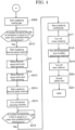
- FIG. 3 and FIG. 4 are flow diagrams showing an example of a thermal spraying process performed by the thermal spraying device 10 according to the present embodiment.
- the worker W engaged in the thermal spraying operation instructs the start of the thermal spraying process by the thermal spraying device 10 via the operation unit 205 of the centralized control board 101.
- the controller 201 of the centralized control board 101 locks the safety door 125 (S301) so that no one can enter the thermal spraying booth 119 during the thermal spraying process.
- the controller 201 checks whether the safety door 125 is locked (S302), and in the case where the safety door 125 is not normally locked (S302; No), returns to step S301.
- the controller 201 may notify the worker W that a problem has occurred in the safety door 125 via the display unit 209.
- the controller 201 confirms the operation of the mover 105 (S303). In the case where the operation of the mover 105 is not normal, (S303; No), the worker W confirms the setting of the mover 105 via the operating unit 205 and changes the setting to a desired setting (S304).
- the controller 201 drives the dust collector 123. (S305). Thereafter, the controller 201 drives the temperature and humidity adjustment machine 121 (S306).
- the controller 201 maintains the temperature and humidity in the thermal spraying booth 119 at a predetermined temperature and a predetermined humidity by the temperature and humidity adjustment machine 121 based on the temperature and humidity in the thermal spraying booth 119 measured by the second sensor 117.
- the controller 201 drives the thermal spraying machine 103 (S307). At this time, the supply of the working gas is also started from the gas feed machine 108 via the thermal spraying control machine 106. Next, the controller 201 drives the rotary machine 113 (S308). When the rotary machine 113 is driven, the workpiece 111 starts rotating at a predetermined speed or at a predetermined angle and a predetermined speed.
- the controller 201 then starts supplying the cooling gas from the cooling gas feed machine 109 to the workpiece 111 (S309).
- the controller 201 acquires the temperature of the surface of the workpiece 111, that is, the surface on which the coating film is formed by the thermal spray material, measured by the first sensor 115, and determines whether or not the temperature of the surface of the base material is equal to or lower than a predetermined temperature (S310). In the case where the surface of the workpiece 111 exceeds the predetermined temperature (S310; No), the controller 201 repeats step S310 until the temperature of the surface of the workpiece 111 becomes equal to or lower than the predetermined temperature.
- the controller 201 starts supplying the thermal spray material from the raw material feeder 107 to the thermal spraying torch 102 via the thermal spraying control machine 106 (S311).
- the thermal spraying torch 102 is moved to a predetermined position by the mover 105, and the thermal spray material is sprayed onto the workpiece 111 to start thermal spraying (S312).
- the predetermined position is a position where the thermal spraying torch 102 is close to the workpiece 111 of the rotary machine 113.
- the controller 201 may tilt the thermal spraying torch 102 at a predetermined angle relative to the surface of the workpiece 111 by the mover 105.
- a coating film with a predetermined film thickness of the thermal spray material is formed on the surface of the workpiece 111 by the thermal spraying.
- the controller 201 stops the thermal spraying by moving the thermal spraying torch 102 away from the workpiece 111 of the rotary machine 113 using the mover 105 (S313).
- the controller 201 stops the supply of the thermal spray material from the raw material feeder 107 to the thermal spraying torch 102 via the thermal spraying control machine 106 (S314). Next, the controller 201 stops the driving of the thermal spraying machine 103 (S315). At this time, the supply of the working gas from the gas feed machine 108 via the thermal spraying control machine 106 is also stopped.
- the controller 201 acquires the temperature of the surface of the workpiece 111, that is, the surface of the coating film made of the thermal spray material, measured by the first sensor 115, and determines whether or not the temperature of the surface of the coating film is equal to or lower than a predetermined temperature (S316). In the case where the surface of the coating film exceeds the predetermined temperature (S316; No), the controller 201 repeats step S316 until the temperature of the surface of the coating film becomes equal to or lower than the predetermined temperature.
- the controller 201 stops the supply of the cooling gas from the cooling gas feed machine 109 to the workpiece 111 (S317).
- controller 201 stops the driving of the rotary machine 113 (S318).
- the controller 201 stops the driving of the temperature and humidity adjustment machine 121 (S319), and stops the driving of the dust collector 123 (S320).
- the driving stop of the temperature and humidity adjustment machine 121 (S319) and the driving stop of the dust collector 123 (S320) may be performed in a different order or at the same time.
- controller 201 unlocks the safety door 125 (S321) and ends the thermal spraying process by the thermal spraying device 10.
- the thermal spraying process performed by the thermal spraying device 10 is collectively controlled by the centralized control board 101. Accordingly, the complexity of the thermal spraying operation can be reduced, and the safety of the operation can be improved. In addition, it is possible to stabilize the quality of the film of the thermal spray material formed on the base material and to improve the reliability of the product.
- thermal spraying device 101: centralized control board
- 102 thermal spraying torch
- 103 thermal spraying machine
- 107 raw material feeder
- 108 gas feed machine
- 109 cooling gas feed machine
- 111 workpiece
- 113 rotary machine
- 115 first sensor
- 117 second sensor
- 119 thermal spraying booth
- 121 temperature and humidity adjustment machine
- 123 dust collector
- 125 safety door
- 203 storage unit
- 207 communication unit
- 209 display unit
Landscapes
- Chemical & Material Sciences (AREA)
- Engineering & Computer Science (AREA)
- Plasma & Fusion (AREA)
- Physics & Mathematics (AREA)
- Materials Engineering (AREA)
- Chemical Kinetics & Catalysis (AREA)
- Mechanical Engineering (AREA)
- Metallurgy (AREA)
- Organic Chemistry (AREA)
- Combustion & Propulsion (AREA)
- Robotics (AREA)
- Coating By Spraying Or Casting (AREA)
- Spray Control Apparatus (AREA)
- Nozzles (AREA)
- Application Of Or Painting With Fluid Materials (AREA)
Abstract
Description
- An embodiment of the present disclosure relates to a thermal spraying device and a thermal spraying control method.
- A thermal spraying device is known in which a film forming material such as a metal or a ceramic is heated to be melted or brought into a state close to melting (semi-melting), and the film forming material that is melted or brought into the semi-melting state is sprayed onto a base material, thereby forming a film of the film forming material on the base material.
- Patent Document 1:
Japanese Examined Utility Model Application Publication No. H5-29092 - In a thermal spraying process, in addition to a thermal spraying device including a thermal spraying torch that sprays a film forming material onto a base material, peripheral devices including a robot that moves the thermal spraying torch, a rotary machine that fixes and rotates the base material, an air feeding device that controls temperature and humidity in a thermal spraying booth, one or more sensors including a thermo-hygrometer that detects temperature and humidity in the thermal spraying booth, an oxygen concentration meter that detects oxygen concentration, a radiation thermometer that detects temperature of a product, a cooling device that cools the product, a dust collecting device that collects dust generated in the thermal spraying booth, and the like are operated.
- The thermal spraying device and its peripheral devices had to be manually operated at the site by workers engaged in thermal spraying operation. Therefore, there is a problem that the thermal spraying operation becomes complicated and the operation efficiency is lowered. There was also a problem in the safety of workers at the site.
- An object of an embodiment of the present disclosure is to provide a thermal spraying device and a thermal spraying control method capable of reducing the complexity of a thermal spraying operation and improving the safety of the operation.
- A thermal spraying device according to an embodiment of the present disclosure includes a thermal spraying machine including a thermal spraying torch spraying a material onto a base material, one or more peripheral devices used with the thermal spraying machine, and a centralized control board enabling centralized operation of the thermal spraying machine and the one or more peripheral devices.
- A thermal spraying control method according to an embodiment of the present disclosure is a thermal spraying method performed by a thermal spraying machine, one or more peripheral devices used with the thermal spraying machine, and a centralized control board, the thermal spraying control method including collectively controlling the thermal spraying machine and the one or more peripheral devices using the centralized control board.
- According to an embodiment of the present disclosure, it is possible to provide a thermal spraying device and a thermal spraying control method capable of reducing the complexity of a thermal spraying operation and improving the safety of the operation.
-
-
FIG. 1 is a diagram for explaining a configuration of a thermal spraying device according to an embodiment of the present disclosure. -
FIG. 2 is a block diagram for explaining an example of a configuration of a centralized control board according to an embodiment. -
FIG. 3 is a flow diagram showing an example of a thermal spraying process performed by a thermal spraying device according to an embodiment. -
FIG. 4 is a flow diagram showing an example of a thermal spraying process performed by a thermal spraying device according to an embodiment. - Hereinafter, embodiments of the present disclosure will be described with reference to the drawings and the like. However, the present invention can be implemented in many different aspects, and should not be construed as being limited to the description of the embodiments exemplified below. In order to make the description clearer, the drawings may be schematically represented with respect to the width, thickness, shape, and the like of each part as compared with the actual embodiment, but are merely examples, and do not limit the interpretation of the present disclosure. In addition, in the present specification and the drawings, the same or similar elements as those already described with respect to the drawings already described are denoted by the same reference signs (or numbers are followed by a, b, A, B, and the like), and detailed description thereof may be omitted as appropriate. Furthermore, the letters "first" and "second" with respect to the respective elements are convenient signs used to distinguish the respective elements, and do not have any further meaning unless otherwise specified.
- In the drawings, although the widths, thicknesses, shapes, and the like of the respective portions may be schematically represented in comparison with the actual embodiments for clarity of explanation, the drawings are merely examples, and do not limit the interpretation of the present invention. In addition, in the present specification and the drawings, elements having the same functions as those described with respect to the drawings already described are denoted by the same reference signs, and redundant description thereof may be omitted.
- As used herein, in the case where a member or region is referred to as being "above (or below)" another member or region, this includes not only the case where it is directly above (or directly below) the other member or region, unless otherwise limited, but also the case where it is above (or below) the other member or region, that is, the case where another component is included between the other member or region.
- Also, in the present specification, expressions "α includes A, B, or C," "α includes any of A, B, or C," "α includes one selected from a group consisting of A, B, and C," and the like does not exclude cases where α includes a plurality of combinations of A to C unless otherwise specified. Furthermore, these expressions do not exclude the case where α includes other elements.
- Hereinafter, a
thermal spraying device 10 according to an embodiment of the present disclosure will be described with reference to the drawings. -
FIG. 1 is a diagram for explaining a configuration of thethermal spraying device 10 according to an embodiment of the present disclosure. Thethermal spraying device 10 includes a centralizedcontrol board 101, athermal spraying machine 103, and peripheral devices. The peripheral devices include amover 105, a coolinggas feed machine 109, arotary machine 113 including a workpiece (base material) 111, afirst sensor 115, and asecond sensor 117. The peripheral devices may include a temperature andhumidity adjustment machine 121 and adust collector 123. In the present embodiment, thethermal spraying machine 103 includes athermal spraying torch 102, a thermalspraying control machine 106, araw material feeder 107, and agas feed machine 108. - In the present embodiment, at least a part of the
thermal spraying machine 103, themover 105, the coolinggas feed machine 109, therotary machine 113, thefirst sensor 115, and thesecond sensor 117 are provided in athermal spraying booth 119 in which a thermal spraying process is performed. The temperature andhumidity adjustment machine 121 has anair duct 122 that connects into thethermal spraying booth 119. Thedust collector 123 has anexhaust duct 124 connecting into thethermal spraying booth 119. Further, thethermal spraying device 10 includes asafety door 125 that allows a worker W to enter and exit the inside and outside of thethermal spraying booth 119. - The
centralized control board 101 is installed outside thethermal spraying booth 119. Thecentralized control board 101 enables the respective components of thethermal spraying device 10 to be operated collectively. That is, thecentralized control board 101 collectively controls operations of thethermal spraying machine 103, themover 105, the coolinggas feed machine 109, therotary machine 113, thefirst sensor 115, thesecond sensor 117, the temperature andhumidity adjustment machine 121, and thedust collector 123. The centralizedcontrol board 101 receives an input operation by the worker W, controls the operation of each component of thethermal spraying device 10, and executes the thermal spraying process in thethermal spraying booth 119. Thecentralized control board 101 may control opening and closing of thesafety door 125. -
FIG. 2 is a block diagram for explaining an example of a configuration of thecentralized control board 101 according to the present embodiment. Thecentralized control board 101 may include acontroller 201, astorage unit 203, anoperation unit 205, acommunication unit 207, and adisplay unit 209. Thecontroller 201, thestorage unit 203, theoperation unit 205, thecommunication unit 207, and thedisplay unit 209 are connected to each other by abus 211. - The
controller 201 includes an arithmetic processor such as a CPU. Thecontroller 201 executes a control program stored in thestorage unit 203 by the CPU to control the operation of thethermal spraying device 10 to realize the thermal spraying process by thethermal spraying device 10. In other words, thecontroller 201 centrally controls the operations of thethermal spraying machine 103, themover 105, the coolinggas feed machine 109, therotary machine 113, thefirst sensor 115, thesecond sensor 117, the temperature andhumidity adjustment machine 121, and thedust collector 123 constituting thethermal spraying device 10. - The
storage unit 203 is a storage device such as a ROM, a RAM or a hard disk. Thestorage unit 203 stores a control program for realizing the thermal spraying process by thethermal spraying device 10. The control program may be provided in a state of being stored in a computer-readable recording medium such as a magnetic recording medium, an optical recording medium, a magnetooptical recording medium, or a semiconductor memory. In this case, thecentralized control board 101 may be provided with a device for reading a recording medium. Further, thestorage unit 203 may store settings of thethermal spraying machine 103, themover 105, the coolinggas feed machine 109, therotary machine 113, thefirst sensor 115, thesecond sensor 117, the temperature andhumidity adjustment machine 121, and thedust collector 123, which constitute thethermal spraying device 10. The control program and the setting of each configuration of thethermal spraying device 10 may be downloaded via a network such as the Internet. - The
operation unit 205 is a device such as an operation panel, an operation button, and a touch panel, and outputs a signal corresponding to the input operation to thecontroller 201. The worker W engaged in the thermal spraying operation controls the operation of thethermal spraying device 10 via theoperation unit 205. The worker W can instruct the start and stop of the thermal spraying process performed by thethermal spraying device 10 via theoperation unit 205. Further, the worker W can appropriately change the settings of thethermal spraying machine 103, themover 105, the coolinggas feed machine 109, therotary machine 113, thefirst sensor 115, thesecond sensor 117, the temperature andhumidity adjustment machine 121, thedust collector 123, and the like, which constitute thethermal spraying device 10 via theoperation unit 205. - The
communication unit 207 performs communication with the respective components of thethermal spraying device 10, that is, thethermal spraying machine 103, themover 105, the coolinggas feed machine 109, therotary machine 113, thefirst sensor 115, thesecond sensor 117, the temperature andhumidity adjustment machine 121, and thedust collector 123, based on the control of thecontroller 201. The communication may be wired communication or wireless communication. In addition, the function of thestorage unit 203 may be realized by an external device that can communicate with thecommunication unit 207. - The
display unit 209 is a display device such as a liquid crystal display or an organic EL display. On thedisplay unit 209, a screen based on the control by thecontroller 201 is displayed to the worker W based on the control by thecontroller 201. For example, thedisplay unit 209 may display setting states and operating states of thethermal spraying machine 103, themover 105, the coolinggas feed machine 109, therotary machine 113, thefirst sensor 115, thesecond sensor 117, the temperature andhumidity adjustment machine 121, and thedust collector 123, and detection results of thefirst sensor 115 and thesecond sensor 117. - Returning to the description of the
thermal spraying device 10 with reference toFIG. 1 . Thethermal spraying machine 103 includes thespraying torch 102 coupled to themover 105 described below. Thethermal spraying torch 102 injects a thermal spray material supplied from theraw material feeder 107 and gas supplied from thegas feed machine 108 through the thermalspraying control machine 106. The thermal spraying by thethermal spraying machine 103 may be gas thermal spraying including flame spraying and high-speed flame spraying, and may be electric thermal spraying including arc spraying and plasma spraying. Thethermal spraying torch 102 melts or semi-melts the thermal spray material by gas or electricity (arc or plasma) to generate thermal spray particles. Thethermal spraying torch 102 accelerates the generated thermal spray particles by gas such as compressed air, and sprays the generated thermal spray particles onto theworkpiece 111 of therotary machine 113 to form a coating film of the thermal spray particles on a surface of theworkpiece 111. - The
mover 105 moves thethermal spraying torch 102 based on the control of thecontroller 201. Themover 105 may be, for example, an industrial robot. Specifically, themover 105 may be a six-axis or seven-axis vertical articulated robot. Themover 105 controls movements of thethermal spraying torch 102 in the front, rear, up, down, left, and right directions, an angle of thethermal spraying torch 102 relative to the surface of theworkpiece 111 of therotary machine 113, and the like, based on the control of thecontroller 201. For example, when the thermal spraying process by thethermal spraying machine 103 is started, themover 105 may move thethermal spraying torch 102 so that thethermal spraying torch 102 approaches theworkpiece 111 of therotary machine 113, and tilt thethermal spraying torch 102 at a predetermined angle relative to the surface of theworkpiece 111. Also, when the thermal spraying process is completed, themover 105 may move thethermal spraying torch 102 away from therotary machine 113. - The thermal
spraying control machine 106 adjusts a supply amount of the thermal spray material supplied from theraw material feeder 107 to thethermal spraying torch 102 based on the control by thecontroller 201 of thecentralized control board 101. Similarly, the thermalspraying control machine 106 adjusts a supply amount of working gas supplied from thegas supplier 108 based on the control by thecontroller 201 of thecentralized control board 101, and supplies the working gas to thethermal spraying torch 102. In an embodiment, the supply amount of thermal spray material supplied from theraw material feeder 107 to thethermal spraying torch 102 may be adjusted directly by thecontroller 201 of thecentralized control board 101. Similarly, in an embodiment, the supply amount of the working gas supplied from thegas feed machine 108 may be adjusted directly by thecontroller 201 of thecentralized control board 101. In such a case, the thermalspraying control machine 106 may be omitted. - The
raw material feeder 107 supplies the thermal spray material to thethermal spraying torch 102 at a predetermined flow rate based on the control of the thermalspraying control machine 106. The thermal spray material may be metal, ceramic, polymer, a composite material such as cermet, or the like. In the present embodiment, although theraw material feeder 107 is installed in thethermal spraying booth 119, at least a part of theraw material feeder 107 may be provided outside thethermal spraying booth 119. The supply amount of the thermal spray material supplied from theraw material feeder 107 to thethermal spraying torch 102 may be directly controlled by thecontroller 201 of thecentralized control board 101. - The
gas feed machine 108 supplies the working gas to thethermal spraying torch 102 through the thermalspraying control machine 106 at a predetermined flow rate based on the control of the thermalspraying control machine 106. In the case where the thermal spraying by thethermal spraying machine 103 is gas spraying, the working gas may be a mixed gas including oxygen (O2) and acetylene. Further, in the case where the thermal spraying by thethermal spraying machine 103 is electric thermal spraying, the working gas may be a gas such as argon (Ar), helium (He), nitrogen (N2), or hydrogen (H2). A supply amount of the working gas supplied from thegas feed machine 108 may be directly controlled by thecontroller 201 of thecentralized control board 101. - The cooling
gas feed machine 109 supplies the cooling gas to theworkpiece 111 of therotary machine 113 at a predetermined flow rate based on the control of thecontroller 201. The cooling gas may be a nitrogen (N2) gas or an argon (Ar) gas. The cooling gas supplied from the coolinggas feed machine 109 cools a thermal sprayed film formed on the surface of theworkpiece 111. - The
rotary machine 113 includes theworkpiece 111. Therotary machine 113 rotates theworkpiece 111 at a predetermined speed based on the control of thecontroller 201. Therotary machine 113 can also rotate theworkpiece 111 at a predetermined angle based on the control of thecontroller 201. The thermal sprayed film is formed on the surface of theworkpiece 111 by the thermal spray material sprayed from the thermal sprayedtorch 102. - The
first sensor 115 measures surface temperature of theworkpiece 111 based on the control of thecontroller 201. Thefirst sensor 115 may be, for example, a radiation temperature sensor. Thefirst sensor 115 transmits the measured surface temperature of the base material to thecontroller 201. Thecontroller 201 controls the coolinggas feed machine 109 to supply the cooling gas to the surface of theworkpiece 111 so that the temperature of the surface of theworkpiece 111 is lowered to a predetermined temperature based on the surface temperature of theworkpiece 111 acquired from thefirst sensor 115. - The
second sensor 117 measures temperature and humidity in thethermal spraying booth 119 based on the control of thecontroller 201. Thesecond sensor 117 may be a temperature and humidity sensor. Thesecond sensor 117 transmits the measured temperature and humidity in thethermal spraying booth 119 to thecontroller 201. Thecontroller 201 controls the temperature andhumidity adjustment machine 121 in order to keep the inside of thethermal spraying booth 119 at a predetermined temperature and humidity based on the temperature and humidity in thethermal spraying booth 119 acquired from thesecond sensor 117. - The temperature and
humidity adjustment machine 121 adjusts the temperature and humidity in thethermal spraying booth 119 based on the control of thecontroller 201. - The
dust collector 123 collects dust generated in thethermal spraying booth 119 based on the control of thecontroller 201. Thedust collector 123 discharges the collected dust to the outside of thethermal spraying booth 119 through theexhaust duct 124. The dust is, for example, a thermal spray material that has not contributed to film formation. The dust may also be a thermal spray material that is melted during thermal spraying and re-solidified by subsequent cooling. - The
safety door 125 allows the worker W to enter and exit thethermal spraying booth 119. An interlock of thesafety door 125 is controlled by thecontroller 201. - The
centralized control board 101 collectively controls the respective components of thethermal spraying device 10 described above. Although not shown, thethermal spraying device 10 may include a power supply device that supplies power to each component of thethermal spraying device 10. In this case, thecentralized control board 101 can control driving of the power supply device. - Although not shown, the
thermal spray device 10 may include a compressor that blows air into thethermal spraying booth 119. The compressor blows air into thethermal spraying booth 119 so that dust generated in thethermal spraying booth 119 can be efficiently collected by thedust collector 123. In this case, thecentralized control board 101 can control driving of the compressor and an amount of air supplied thereof. - Although not shown, the
thermal spraying device 10 may include an oxygen concentration sensor that detects oxygen concentration in thethermal spraying booth 119. - As described above, in the present embodiment, the operation of each component of the
thermal spraying device 10 is collectively controlled by thecentralized control board 101. Accordingly, the complexity of the thermal spraying operation can be reduced, and the safety of the operation can be improved. In addition, it is possible to stabilize the quality of the film of the thermal spray material formed on the base material and to improve the reliability of a product. - A flow of a thermal spraying process performed by the
thermal spraying device 10 according to the present embodiment will be described.FIG. 3 andFIG. 4 are flow diagrams showing an example of a thermal spraying process performed by thethermal spraying device 10 according to the present embodiment. - The worker W engaged in the thermal spraying operation instructs the start of the thermal spraying process by the
thermal spraying device 10 via theoperation unit 205 of thecentralized control board 101. When the thermal spraying process is started, thecontroller 201 of thecentralized control board 101 locks the safety door 125 (S301) so that no one can enter thethermal spraying booth 119 during the thermal spraying process. Thecontroller 201 checks whether thesafety door 125 is locked (S302), and in the case where thesafety door 125 is not normally locked (S302; No), returns to step S301. Further, although not shown, in the case where a state in which thesafety door 125 is not normally locked continues despite an instruction to start the thermal spraying process, thecontroller 201 may notify the worker W that a problem has occurred in thesafety door 125 via thedisplay unit 209. - In the case where the
safety door 125 is normally locked (S302; Yes), thecontroller 201 confirms the operation of the mover 105 (S303). In the case where the operation of themover 105 is not normal, (S303; No), the worker W confirms the setting of themover 105 via theoperating unit 205 and changes the setting to a desired setting (S304). - In the case where the setting of the
mover 105 is normal, that is, in the case where the setting of themover 105 is a desired setting (S303; Yes), thecontroller 201 drives thedust collector 123. (S305). Thereafter, thecontroller 201 drives the temperature and humidity adjustment machine 121 (S306). Thecontroller 201 maintains the temperature and humidity in thethermal spraying booth 119 at a predetermined temperature and a predetermined humidity by the temperature andhumidity adjustment machine 121 based on the temperature and humidity in thethermal spraying booth 119 measured by thesecond sensor 117. - Subsequently, the
controller 201 drives the thermal spraying machine 103 (S307). At this time, the supply of the working gas is also started from thegas feed machine 108 via the thermalspraying control machine 106. Next, thecontroller 201 drives the rotary machine 113 (S308). When therotary machine 113 is driven, theworkpiece 111 starts rotating at a predetermined speed or at a predetermined angle and a predetermined speed. - In addition, the respective processes from the driving of the dust collector 123 (S305) to the driving of the rotary machine 113 (S308) may be performed in a different order or simultaneously.
- The
controller 201 then starts supplying the cooling gas from the coolinggas feed machine 109 to the workpiece 111 (S309). - The
controller 201 acquires the temperature of the surface of theworkpiece 111, that is, the surface on which the coating film is formed by the thermal spray material, measured by thefirst sensor 115, and determines whether or not the temperature of the surface of the base material is equal to or lower than a predetermined temperature (S310). In the case where the surface of theworkpiece 111 exceeds the predetermined temperature (S310; No), thecontroller 201 repeats step S310 until the temperature of the surface of theworkpiece 111 becomes equal to or lower than the predetermined temperature. - In the case where the surface of the base material (workpiece 111) is at or below a predetermined temperature (S310; Yes), the
controller 201 starts supplying the thermal spray material from theraw material feeder 107 to thethermal spraying torch 102 via the thermal spraying control machine 106 (S311). Next, thethermal spraying torch 102 is moved to a predetermined position by themover 105, and the thermal spray material is sprayed onto theworkpiece 111 to start thermal spraying (S312). Here, the predetermined position is a position where thethermal spraying torch 102 is close to theworkpiece 111 of therotary machine 113. In addition, thecontroller 201 may tilt thethermal spraying torch 102 at a predetermined angle relative to the surface of theworkpiece 111 by themover 105. A coating film with a predetermined film thickness of the thermal spray material is formed on the surface of theworkpiece 111 by the thermal spraying. - When the coating film is formed on the surface of the base material with the predetermined film thickness, the
controller 201 stops the thermal spraying by moving thethermal spraying torch 102 away from theworkpiece 111 of therotary machine 113 using the mover 105 (S313). - The
controller 201 stops the supply of the thermal spray material from theraw material feeder 107 to thethermal spraying torch 102 via the thermal spraying control machine 106 (S314). Next, thecontroller 201 stops the driving of the thermal spraying machine 103 (S315). At this time, the supply of the working gas from thegas feed machine 108 via the thermalspraying control machine 106 is also stopped. - The
controller 201 acquires the temperature of the surface of theworkpiece 111, that is, the surface of the coating film made of the thermal spray material, measured by thefirst sensor 115, and determines whether or not the temperature of the surface of the coating film is equal to or lower than a predetermined temperature (S316). In the case where the surface of the coating film exceeds the predetermined temperature (S316; No), thecontroller 201 repeats step S316 until the temperature of the surface of the coating film becomes equal to or lower than the predetermined temperature. - When the temperature of the surface of the coating film becomes equal to or lower than the predetermined temperature (S316; Yes), the
controller 201 stops the supply of the cooling gas from the coolinggas feed machine 109 to the workpiece 111 (S317). - Thereafter, the
controller 201 stops the driving of the rotary machine 113 (S318). - Thereafter, the
controller 201 stops the driving of the temperature and humidity adjustment machine 121 (S319), and stops the driving of the dust collector 123 (S320). The driving stop of the temperature and humidity adjustment machine 121 (S319) and the driving stop of the dust collector 123 (S320) may be performed in a different order or at the same time. - Finally, the
controller 201 unlocks the safety door 125 (S321) and ends the thermal spraying process by thethermal spraying device 10. - As described above, the thermal spraying process performed by the
thermal spraying device 10 is collectively controlled by thecentralized control board 101. Accordingly, the complexity of the thermal spraying operation can be reduced, and the safety of the operation can be improved. In addition, it is possible to stabilize the quality of the film of the thermal spray material formed on the base material and to improve the reliability of the product. - Based on the embodiments of the present disclosure described above, additions, deletions, or design changes made by a person skilled in the art are also included in a scope of the present invention as long as the present invention is provided.
- In addition, it is to be understood that the present invention provides other operational effects that are different from operational effects provided by aspects of the embodiments described above, and those that are obvious from descriptions of the present specification or those that can be easily predicted by a person skilled in the art.
- 10: thermal spraying device, 101: centralized control board, 102: thermal spraying torch, 103: thermal spraying machine, 105: mover, 107: raw material feeder, 108: gas feed machine, 109: cooling gas feed machine, 111: workpiece, 113: rotary machine, 115: first sensor, 117: second sensor, 119: thermal spraying booth, 121: temperature and humidity adjustment machine, 123: dust collector, 125: safety door, 201: controller, 203: storage unit, 205: operation unit, 207: communication unit, 209: display unit
Claims (9)
- A thermal spraying device comprising:a thermal spraying machine including a thermal spraying torch thermally spraying a material onto a base material;one or more peripheral devices used with the thermal spraying machine; anda centralized control board enabling centralized operation of the thermal spraying machine and the one or more peripheral devices.
- The thermal spraying device according to claim 1, wherein the oner or more peripheral devices include at least one selected from a group including a mover moving the thermal spraying torch, a raw material feeder supplying the material, a rotary machine fixing and rotating the base material, a temperature and humidity adjustment machine controlling temperature and humidity in a thermal spraying booth, a temperature and humidity sensor detecting temperature and humidity in the thermal spraying booth, an oxygen concentration sensor detecting oxygen concentration in the thermal spraying booth, a radiation temperature sensor detecting temperature on the base material, a cooling gas feed machine cooling the base material, and a dust collector collecting dust generated in the thermal spraying booth.
- The thermal spraying device according to claim 1 or 2, wherein the centralized control board includes a controller that collectively controls the thermal spraying machine and the one or more peripheral devices.
- The thermal spraying device according to claim 3, wherein the controller controls the temperature and humidity adjustment machine based on a detection result of the temperature and humidity sensor.
- The thermal spraying device according to claim 3 or 4, wherein the controller controls the cooling gas feed machine based on a result of the radiation temperature sensor.
- A thermal spraying control method performed by a thermal spraying machine, one or more peripheral devices used with the thermal spraying machine, and a centralized control board, the thermal spraying control method comprising:
collectively controlling the thermal spraying machine and the one or more peripheral devices using the centralized control board. - The thermal spraying control method according to claim 6, wherein the one or more peripheral devices include at least one selected from a group including a mover moving the thermal spraying torch, a raw material feeder supplying the material, a rotary machine fixing and rotating the base material, a temperature and humidity adjustment machine controlling temperature and humidity in a thermal spraying booth, a temperature and humidity sensor detecting temperature and humidity in the thermal spraying booth, an oxygen concentration sensor detecting oxygen concentration in the thermal spraying booth, a radiation temperature sensor detecting temperature on the base material, a cooling gas feed machine cooling the base material and a dust collector collecting dust generated in the thermal spraying booth.
- The thermal spraying control method according to claim 7, wherein the centralized control board includes a controller that collectively controls the thermal spraying machine and the one or more peripheral devices, the thermal spraying control method comprising:when the centralized control board receives an instruction to start a thermal spraying operation, maintaining temperature and humidity in the thermal spraying booth at a predetermined temperature and a predetermined humidity by the controller, based on a detection result of the temperature and humidity sensor;determining whether a surface temperature of the base material is below a predetermined temperature by the controller, based on a detection result of the radiation temperature sensor; andin the case where a result of the determination is that the surface temperature of the base material is below the predetermined temperature, driving the thermal spraying machine by the controller to form a coating including the material on the surface of the base material.
- The thermal spraying control method according to claim 8, further comprising, after the coating is formed, supplying cooling gas to the coating by controlling the cooling gas supply machine, by the controller, until a surface temperature of the coating formed on the base material is below a predetermined temperature based on the detection result of the radiation temperature sensor.
Applications Claiming Priority (2)
| Application Number | Priority Date | Filing Date | Title |
|---|---|---|---|
| JP2022036190A JP7841908B2 (en) | 2022-03-09 | 2022-03-09 | Thermal spraying apparatus and thermal spraying control method |
| PCT/JP2023/007043 WO2023171444A1 (en) | 2022-03-09 | 2023-02-27 | Thermal spraying device and thermal spraying control method |
Publications (2)
| Publication Number | Publication Date |
|---|---|
| EP4491757A1 true EP4491757A1 (en) | 2025-01-15 |
| EP4491757A4 EP4491757A4 (en) | 2026-03-04 |
Family
ID=87935158
Family Applications (1)
| Application Number | Title | Priority Date | Filing Date |
|---|---|---|---|
| EP23766622.7A Pending EP4491757A4 (en) | 2022-03-09 | 2023-02-27 | Thermal spraying device and thermal spraying control method |
Country Status (7)
| Country | Link |
|---|---|
| US (1) | US20240425964A1 (en) |
| EP (1) | EP4491757A4 (en) |
| JP (2) | JP7841908B2 (en) |
| KR (1) | KR20240157055A (en) |
| CN (1) | CN118871606A (en) |
| TW (1) | TWI858591B (en) |
| WO (1) | WO2023171444A1 (en) |
Family Cites Families (14)
| Publication number | Priority date | Publication date | Assignee | Title |
|---|---|---|---|---|
| JPH02305951A (en) * | 1989-05-19 | 1990-12-19 | Komatsu Ltd | Cooling method and equipment after reduced pressure spraying |
| JPH0529092A (en) | 1991-07-18 | 1993-02-05 | Hitachi Medical Corp | X-ray high voltage device |
| JPH0529092U (en) | 1991-08-29 | 1993-04-16 | ヤン チヤン アツキ ジエジヨ ジユシグヘサ | Electronic musical instrument keyboard |
| DE10025161A1 (en) * | 2000-05-23 | 2001-11-29 | Joma Chemicals As Limingen | Material and method for producing a corrosion- and wear-resistant layer by thermal peaking |
| US6648053B2 (en) * | 2001-04-18 | 2003-11-18 | Ford Motor Company | Method and apparatus for controlling a spray form process based on sensed surface temperatures |
| FR2836621B1 (en) * | 2002-02-28 | 2004-04-16 | Snecma Services | THERMAL PROJECTION INSTRUMENT |
| US8210120B2 (en) * | 2003-01-10 | 2012-07-03 | Microsemi Corporation | Systems and methods for building tamper resistant coatings |
| JP2006257459A (en) * | 2005-03-15 | 2006-09-28 | Fuji Heavy Ind Ltd | Thermal spraying method and thermal spraying equipment |
| US7189335B1 (en) * | 2005-08-31 | 2007-03-13 | Honeywell International Inc. | Conformal coverings for electronic devices |
| US20130298828A1 (en) * | 2012-05-09 | 2013-11-14 | Murray N. Underhill | Thermal spray apparatus |
| DE102013111179A1 (en) * | 2013-10-09 | 2015-04-09 | Pilz Gmbh. & Co. Kg | Modular control device with load monitoring |
| JP6741410B2 (en) * | 2015-09-25 | 2020-08-19 | 株式会社フジミインコーポレーテッド | Spraying slurry, sprayed coating and method for forming sprayed coating |
| US10829845B2 (en) * | 2017-01-06 | 2020-11-10 | General Electric Company | Selective thermal coating of cooling holes with air flow |
| WO2020031697A1 (en) * | 2018-08-06 | 2020-02-13 | 東京エレクトロン株式会社 | Thermal spray system, thermal spray method and method for producing lithium secondary battery |
-
2022
- 2022-03-09 JP JP2022036190A patent/JP7841908B2/en active Active
-
2023
- 2023-02-27 WO PCT/JP2023/007043 patent/WO2023171444A1/en not_active Ceased
- 2023-02-27 CN CN202380025707.5A patent/CN118871606A/en active Pending
- 2023-02-27 KR KR1020247032251A patent/KR20240157055A/en active Pending
- 2023-02-27 EP EP23766622.7A patent/EP4491757A4/en active Pending
- 2023-03-08 TW TW112108406A patent/TWI858591B/en active
-
2024
- 2024-09-06 US US18/826,386 patent/US20240425964A1/en active Pending
-
2025
- 2025-11-19 JP JP2025199110A patent/JP2026020283A/en active Pending
Also Published As
| Publication number | Publication date |
|---|---|
| JP7841908B2 (en) | 2026-04-07 |
| JP2023131433A (en) | 2023-09-22 |
| CN118871606A (en) | 2024-10-29 |
| EP4491757A4 (en) | 2026-03-04 |
| WO2023171444A1 (en) | 2023-09-14 |
| TWI858591B (en) | 2024-10-11 |
| JP2026020283A (en) | 2026-02-06 |
| US20240425964A1 (en) | 2024-12-26 |
| KR20240157055A (en) | 2024-10-31 |
| TW202336247A (en) | 2023-09-16 |
Similar Documents
| Publication | Publication Date | Title |
|---|---|---|
| CN107931781B (en) | Double metallic composite material electric arc increasing material manufacturing device and its manufacturing method | |
| CA1298882C (en) | Automatic working method and automatic working machine | |
| US20060108960A1 (en) | Robot controller and robot system | |
| TW201023998A (en) | Automation concept for a metallurgical plant or rolling mill | |
| JPS60502193A (en) | Laser machining system | |
| JP2000271888A (en) | Robot controller | |
| US20240425964A1 (en) | Thermal spraying equipment and thermal spraying control method | |
| JP5507194B2 (en) | Plasma cutting method and plasma cutting apparatus | |
| US20230010975A1 (en) | Robot system | |
| WO2022230143A1 (en) | Device for setting safety parameters, teaching device and method | |
| US8436272B2 (en) | Systems and methods to position web processing equipment | |
| Piazza et al. | EAF process optimization through a modular automation system and an adaptive control strategy | |
| CN212526455U (en) | Self-adaptive single-side welding double-side forming plasma welding system based on laser vision | |
| Ertveldt et al. | The effect of weave in directed energy deposition of thin walled geometries | |
| JP2023131433A5 (en) | ||
| CN219266110U (en) | Detection equipment and system for fixed electric furnace lining | |
| RU202295U1 (en) | Device for laser multilayer cladding of powder materials | |
| JP2021077074A (en) | Numerical control device and method for controlling numerical control device | |
| EP3943256A1 (en) | Robot system | |
| JP7735900B2 (en) | Control device, machine tool, control method, and computer program | |
| CN118168337A (en) | A supersonic gas-solid cyclone injection smelting system and method | |
| JPH0494883A (en) | Robot processing control method | |
| JPH02152724A (en) | Wire electro-discharge machining unit | |
| JPH04128906A (en) | Laser beam device | |
| JPH10315169A (en) | Manipulator controller |
Legal Events
| Date | Code | Title | Description |
|---|---|---|---|
| STAA | Information on the status of an ep patent application or granted ep patent |
Free format text: STATUS: THE INTERNATIONAL PUBLICATION HAS BEEN MADE |
|
| PUAI | Public reference made under article 153(3) epc to a published international application that has entered the european phase |
Free format text: ORIGINAL CODE: 0009012 |
|
| STAA | Information on the status of an ep patent application or granted ep patent |
Free format text: STATUS: REQUEST FOR EXAMINATION WAS MADE |
|
| 17P | Request for examination filed |
Effective date: 20240918 |
|
| AK | Designated contracting states |
Kind code of ref document: A1 Designated state(s): AL AT BE BG CH CY CZ DE DK EE ES FI FR GB GR HR HU IE IS IT LI LT LU LV MC ME MK MT NL NO PL PT RO RS SE SI SK SM TR |
|
| DAV | Request for validation of the european patent (deleted) | ||
| DAX | Request for extension of the european patent (deleted) | ||
| A4 | Supplementary search report drawn up and despatched |
Effective date: 20260203 |
|
| RIC1 | Information provided on ipc code assigned before grant |
Ipc: C23C 4/00 20160101AFI20260128BHEP Ipc: B05B 7/16 20060101ALI20260128BHEP Ipc: B05B 12/12 20060101ALI20260128BHEP Ipc: B05D 1/08 20060101ALI20260128BHEP Ipc: B05D 3/00 20060101ALI20260128BHEP |