EP4491590A1 - Method for manufacturing quartz member, and silica powder thermal spray coating method - Google Patents
Method for manufacturing quartz member, and silica powder thermal spray coating method Download PDFInfo
- Publication number
- EP4491590A1 EP4491590A1 EP23766927.0A EP23766927A EP4491590A1 EP 4491590 A1 EP4491590 A1 EP 4491590A1 EP 23766927 A EP23766927 A EP 23766927A EP 4491590 A1 EP4491590 A1 EP 4491590A1
- Authority
- EP
- European Patent Office
- Prior art keywords
- burner
- silica powder
- quartz
- manufacturing
- oxygen gas
- Prior art date
- Legal status (The legal status is an assumption and is not a legal conclusion. Google has not performed a legal analysis and makes no representation as to the accuracy of the status listed.)
- Pending
Links
Images
Classifications
-
- C—CHEMISTRY; METALLURGY
- C03—GLASS; MINERAL OR SLAG WOOL
- C03B—MANUFACTURE, SHAPING, OR SUPPLEMENTARY PROCESSES
- C03B20/00—Processes specially adapted for the production of quartz or fused silica articles, not otherwise provided for
-
- C—CHEMISTRY; METALLURGY
- C09—DYES; PAINTS; POLISHES; NATURAL RESINS; ADHESIVES; COMPOSITIONS NOT OTHERWISE PROVIDED FOR; APPLICATIONS OF MATERIALS NOT OTHERWISE PROVIDED FOR
- C09D—COATING COMPOSITIONS, e.g. PAINTS, VARNISHES OR LACQUERS; FILLING PASTES; CHEMICAL PAINT OR INK REMOVERS; INKS; CORRECTING FLUIDS; WOODSTAINS; PASTES OR SOLIDS FOR COLOURING OR PRINTING; USE OF MATERIALS THEREFOR
- C09D1/00—Coating compositions, e.g. paints, varnishes or lacquers, based on inorganic substances
-
- C—CHEMISTRY; METALLURGY
- C01—INORGANIC CHEMISTRY
- C01B—NON-METALLIC ELEMENTS; COMPOUNDS THEREOF; METALLOIDS OR COMPOUNDS THEREOF NOT COVERED BY SUBCLASS C01C
- C01B33/00—Silicon; Compounds thereof
- C01B33/113—Silicon oxides; Hydrates thereof
- C01B33/12—Silica; Hydrates thereof, e.g. lepidoic silicic acid
-
- C—CHEMISTRY; METALLURGY
- C03—GLASS; MINERAL OR SLAG WOOL
- C03B—MANUFACTURE, SHAPING, OR SUPPLEMENTARY PROCESSES
- C03B19/00—Other methods of shaping glass
- C03B19/01—Other methods of shaping glass by progressive fusion or sintering of powdered glass onto a shaping substrate, i.e. accretion, e.g. plasma oxidation deposition
-
- C—CHEMISTRY; METALLURGY
- C03—GLASS; MINERAL OR SLAG WOOL
- C03C—CHEMICAL COMPOSITION OF GLASSES, GLAZES OR VITREOUS ENAMELS; SURFACE TREATMENT OF GLASS; SURFACE TREATMENT OF FIBRES OR FILAMENTS MADE FROM GLASS, MINERALS OR SLAGS; JOINING GLASS TO GLASS OR OTHER MATERIALS
- C03C17/00—Surface treatment of glass, not in the form of fibres or filaments, by coating
- C03C17/02—Surface treatment of glass, not in the form of fibres or filaments, by coating with glass
-
- C—CHEMISTRY; METALLURGY
- C03—GLASS; MINERAL OR SLAG WOOL
- C03C—CHEMICAL COMPOSITION OF GLASSES, GLAZES OR VITREOUS ENAMELS; SURFACE TREATMENT OF GLASS; SURFACE TREATMENT OF FIBRES OR FILAMENTS MADE FROM GLASS, MINERALS OR SLAGS; JOINING GLASS TO GLASS OR OTHER MATERIALS
- C03C3/00—Glass compositions
- C03C3/04—Glass compositions containing silica
- C03C3/06—Glass compositions containing silica with more than 90% silica by weight, e.g. quartz
-
- C—CHEMISTRY; METALLURGY
- C23—COATING METALLIC MATERIAL; COATING MATERIAL WITH METALLIC MATERIAL; CHEMICAL SURFACE TREATMENT; DIFFUSION TREATMENT OF METALLIC MATERIAL; COATING BY VACUUM EVAPORATION, BY SPUTTERING, BY ION IMPLANTATION OR BY CHEMICAL VAPOUR DEPOSITION, IN GENERAL; INHIBITING CORROSION OF METALLIC MATERIAL OR INCRUSTATION IN GENERAL
- C23C—COATING METALLIC MATERIAL; COATING MATERIAL WITH METALLIC MATERIAL; SURFACE TREATMENT OF METALLIC MATERIAL BY DIFFUSION INTO THE SURFACE, BY CHEMICAL CONVERSION OR SUBSTITUTION; COATING BY VACUUM EVAPORATION, BY SPUTTERING, BY ION IMPLANTATION OR BY CHEMICAL VAPOUR DEPOSITION, IN GENERAL
- C23C4/00—Coating by spraying the coating material in the molten state, e.g. by flame, plasma or electric discharge
- C23C4/04—Coating by spraying the coating material in the molten state, e.g. by flame, plasma or electric discharge characterised by the coating material
- C23C4/10—Oxides, borides, carbides, nitrides or silicides; Mixtures thereof
- C23C4/11—Oxides
-
- C—CHEMISTRY; METALLURGY
- C23—COATING METALLIC MATERIAL; COATING MATERIAL WITH METALLIC MATERIAL; CHEMICAL SURFACE TREATMENT; DIFFUSION TREATMENT OF METALLIC MATERIAL; COATING BY VACUUM EVAPORATION, BY SPUTTERING, BY ION IMPLANTATION OR BY CHEMICAL VAPOUR DEPOSITION, IN GENERAL; INHIBITING CORROSION OF METALLIC MATERIAL OR INCRUSTATION IN GENERAL
- C23C—COATING METALLIC MATERIAL; COATING MATERIAL WITH METALLIC MATERIAL; SURFACE TREATMENT OF METALLIC MATERIAL BY DIFFUSION INTO THE SURFACE, BY CHEMICAL CONVERSION OR SUBSTITUTION; COATING BY VACUUM EVAPORATION, BY SPUTTERING, BY ION IMPLANTATION OR BY CHEMICAL VAPOUR DEPOSITION, IN GENERAL
- C23C4/00—Coating by spraying the coating material in the molten state, e.g. by flame, plasma or electric discharge
- C23C4/12—Coating by spraying the coating material in the molten state, e.g. by flame, plasma or electric discharge characterised by the method of spraying
- C23C4/129—Flame spraying
-
- F—MECHANICAL ENGINEERING; LIGHTING; HEATING; WEAPONS; BLASTING
- F23—COMBUSTION APPARATUS; COMBUSTION PROCESSES
- F23D—BURNERS
- F23D14/00—Burners for combustion of a gas, e.g. of a gas stored under pressure as a liquid
- F23D14/20—Non-premix gas burners, i.e. in which gaseous fuel is mixed with combustion air on arrival at the combustion zone
- F23D14/22—Non-premix gas burners, i.e. in which gaseous fuel is mixed with combustion air on arrival at the combustion zone with separate air and gas feed ducts, e.g. with ducts running parallel or crossing each other
-
- C—CHEMISTRY; METALLURGY
- C01—INORGANIC CHEMISTRY
- C01P—INDEXING SCHEME RELATING TO STRUCTURAL AND PHYSICAL ASPECTS OF SOLID INORGANIC COMPOUNDS
- C01P2006/00—Physical properties of inorganic compounds
- C01P2006/80—Compositional purity
-
- C—CHEMISTRY; METALLURGY
- C03—GLASS; MINERAL OR SLAG WOOL
- C03C—CHEMICAL COMPOSITION OF GLASSES, GLAZES OR VITREOUS ENAMELS; SURFACE TREATMENT OF GLASS; SURFACE TREATMENT OF FIBRES OR FILAMENTS MADE FROM GLASS, MINERALS OR SLAGS; JOINING GLASS TO GLASS OR OTHER MATERIALS
- C03C2203/00—Production processes
- C03C2203/10—Melting processes
-
- H—ELECTRICITY
- H10—SEMICONDUCTOR DEVICES; ELECTRIC SOLID-STATE DEVICES NOT OTHERWISE PROVIDED FOR
- H10P—GENERIC PROCESSES OR APPARATUS FOR THE MANUFACTURE OR TREATMENT OF DEVICES COVERED BY CLASS H10
- H10P72/00—Handling or holding of wafers, substrates or devices during manufacture or treatment thereof
- H10P72/70—Handling or holding of wafers, substrates or devices during manufacture or treatment thereof for supporting or gripping
- H10P72/76—Handling or holding of wafers, substrates or devices during manufacture or treatment thereof for supporting or gripping using mechanical means, e.g. clamps or pinches
- H10P72/7604—Handling or holding of wafers, substrates or devices during manufacture or treatment thereof for supporting or gripping using mechanical means, e.g. clamps or pinches the wafers being placed on a susceptor, stage or support
- H10P72/7616—Handling or holding of wafers, substrates or devices during manufacture or treatment thereof for supporting or gripping using mechanical means, e.g. clamps or pinches the wafers being placed on a susceptor, stage or support characterised by a coating, a hardness or a material
Definitions
- the present invention relates to a manufacturing method of a quartz member, and a method for forming a quartz glass coating on a target member.
- Quartz members obtained by spray coating quartz glass are used as machines, devices, containers, or the like used in semiconductor manufacturing processes.
- Patent Literature 1 describes a method of depositing a coating on a quartz member using a quartz oxyhydrogen burner.
- Patent Literature 2 describes a method for forming a quartz glass sprayed film on a side surface of a substrate using a plasma spray method.
- An object of the present invention is to provide a method for manufacturing a quartz member having a dense coating film without bubbles, a method for spray coating silica powder that can perform quartz coating at an arbitrary processing angle on a substrate having an arbitrary shape, and further a burner for the method.
- the inventors conducted extensive research to solve the above problem based on an understanding of the physicochemical phenomenology that acts on raw material particles up to the melting and film-forming stage, and discovered that the above problem can be solved by forming a coating using an oxyhydrogen burner made of quartz, and supplying silica powder as a raw material with a carrier gas at an arbitrary feed rate, thus arriving at the present invention. That is, the present invention is as follows.
- the present invention also includes the following aspects.
- the present invention increases the freedom of choice of the shape of the member to be coated, and the coating process can be performed from an arbitary angle.
- a quartz member having a dense coating film without bubbles can be manufactured.
- a coating film that is high in purity, smooth, and without bubbles can be formed.
- the method for manufacturing a quartz member of the present invention includes a step of spraying a carrier gas containing silica powder onto a surface of a target member through a burner, wherein the step is performed in an oxyhydrogen flame atmosphere, and the temperature of the target member surface is 1401°C or higher and 2000°C or lower.
- the method for manufacturing a quartz member of the present invention includes a step of thermally spraying silica powder onto a target member surface.
- the temperature at which the silica powder is sprayed onto the target member surface is preferably 1401°C or higher, more preferably 1500°C or higher, even more preferably 1600°C or higher, even more preferably 1700°C or higher, and most preferably 1750°C or higher, from the viewpoint of melting and sintering the silica powder on the target member surface. Also, from the viewpoint of sintering the silica powder without vaporizing it, it is preferably 2000°C or lower, more preferably 1950°C or lower, even more preferably 1900°C or lower, and even more preferably 1850°C or lower.
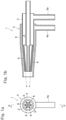
- FIG. 1 shows a burner 1, which is an example of a burner according to an embodiment of the present invention, wherein FIG. 1a is a front view and FIG. 1b is a cross-sectional view along the line B-B in FIG. 1a .
- the burner used in the present invention has a supply pipe for silica powder, which is the raw material.
- the method for supplying silica powder is not particularly limited, but it is preferable to use a silica powder feed device, which will be described later.
- the burner used in the present invention has a supply tube for the gas to be burned.
- the gas to be burned is not particularly limited, but from the viewpoints of flammability and safety, hydrogen and oxygen are preferable.
- the burner used in the present invention preferably has a cross-section with a multi-layer structure from the viewpoints of stable supply of raw materials and gases and safety.
- the number of structures in the multi-layer structure is not particularly limited, but when oxygen gas, hydrogen gas, and silica powder are supplied, it is preferable to have three or more structures, as in the burner 1 shown in FIG. 1 .
- the burner has a supply tube configuration in which the silica powder supply tube, the oxygen gas supply tube, and the hydrogen gas supply tube are arranged in this order in the radial direction from the center of the cross section of the burner. Furthermore, it is preferable that the burner has a structure in which part of the hydrogen gas is introduced into the gaps between the oxygen gas nozzles.
- the burner has a tapered portion from a body to a tip thereof, and that the tapered portion has oxygen gas nozzles arranged on a concentric circle.
- the tapered portion may be configured so that a single circular nozzle covers the nozzles on the center side.
- the number of oxygen gas nozzles arranged on a concentric circle is preferably four or more, more preferably five or more, and even more preferably six or more.
- the burner 1, which is an example of a burner used in the present invention, has a body 5.
- the body 5 has a three or more multiple tube structure in which a supply tube 2 of the silica powder as the raw material, an oxygen gas supply tube 3, and a hydrogen gas supply tube 4 are arranged in this order in the radial direction from the center of the body.
- the rear ends of the oxygen gas supply tube 3 and the hydrogen gas supply tube 4 are closed with a closing member (not shown) respectively.
- the oxygen gas supply tube 3 and the hydrogen gas supply tube 4 are provided with gas introduction portions 3a and 4a.
- the burner 1 has a tapered section T that becomes narrower toward the tip from the body 5 to the tip thereof.
- the burner has oxygen gas nozzles 6 arranged at equal circumferential positions on a concentric circle in the tapered section T. Part of the hydrogen gas is introduced into the gaps between the oxygen gas nozzles 6. The tip side of the oxygen gas supply tube 3 is communicated only with the oxygen gas nozzles 6. Six oxygen gas nozzles 6 are shown, but this is not limited to this.
- the burner used in the present invention preferably has a convergence point for the blowing flows of raw silica powder, oxygen gas, and hydrogen gas in front of the burner, from the viewpoint of forming a dense coating film.
- the burner 1, which is an example of a burner used in the present invention, has a convergence point in front of it for the blowing flows of raw silica powder, oxygen gas, and hydrogen gas.
- the axial direction of each oxygen gas nozzle 6 is directed toward the convergence point.
- the material of the burner used in the manufacturing method of the present invention is not particularly limited, but it is preferable that the burner is made of quartz from the viewpoint of heat resistance.
- the silica powder as the raw material has high purity (e.g., over 5N), since this increases the purity of a film to be formed.
- silica powder with a purity of 5N or less, such as natural quartz powder may be used.
- the particle size of silica powder as the raw material is usually 20-400 ⁇ m, preferably 40-200 ⁇ m, and more preferably 50-80 ⁇ m.
- the target member on which the coating is to be formed is preferably a quartz jig, examples of which include an etching ring in a plasma etching apparatus, a quartz plate, a rectangular cleaning tank, and a furnace tube used in an apparatus for forming an oxide coating on a semiconductor wafer.
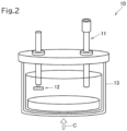
- a silica powder feeding device 10 has a hopper 13 for storing silica powder as the raw material, and a suction line 11 made of a quartz tube for sucking up the silica powder in the hopper 13.
- the silica powder as the raw material is sucked up into the suction line 11 together with the carrier gas by the negative pressure generated by the ejection of oxygen gas and hydrogen gas from the burner 1.
- a quartz scraper 12 is provided as a member for smoothing the top surface of the silica powder stored in the hopper 13.
- the tube and scraper are made of quartz.
- the carrier gas is introduced into the hopper 13 from near the center of the bottom of the hopper 13, as shown by an arrow C. Nitrogen gas, oxygen gas, air, or the like is used as the carrier gas.
- the manufacturing method of the quartz member of the present invention includes a step of thermally spraying silica powder onto a surface of a target member.
- the tip of the burner 1 is positioned toward the target member, and the distance from the tip of the burner 1 to the target member is adjusted.
- the surface temperature of the target member when spraying the silica powder onto the surface of the target member is preferably 1401°C or higher, more preferably 1500°C or higher, even more preferably 1600°C or higher, even more preferably 1700°C or higher, and most preferably 1750°C or higher, from the viewpoint of melting and sintering the silica powder on the surface of the target member.
- the temperature is preferably 2000°C or less, more preferably 1950°C or less, even more preferably 1900°C or less, and even more preferably 1850°C or less.
- the above temperature is measured by measuring the surface temperature of the target material while the burner is flaming without supplying the silica powder as the raw material.
- silica powder as the raw material is supplied. Then, a step of coating the surface of the target material is performed by moving the burner or by moving the target material while keeping the distance from the tip of the burner to the target material constant.
- the coating does not need to be formed on the entire surface of the target material, and only a part of the target material may be coated with the coating.
- Silica powder as the raw material does not need to be always supplied. After a predetermined coating thickness is obtained, a flattening process of the coating surface may be performed by heating the coating surface with only the oxyhydrogen flame.
- a flat quartz plate with a diameter of 150 mm and a thickness of 30 mm was used as the target material.
- the quartz plate was fixed on a horizontal turntable.
- the burner 1 in Fig. 1 was fixed facing downwards with the tip of the burner 150 mm away from the target material.
- the spraying location on the target material was located 60 mm away from the center of rotation of the turntable.
- Silica powder with an average particle size of 200 ⁇ m (metallic impurity amount 0.1 ppm or less, 4N) was supplied at 6 g/min with a carrier gas flow rate of 2 L/min, and the silica powder was melted and coated with an oxyhydrogen flame under conditions of a hydrogen gas flow rate of 80 L/min and an oxygen gas flow rate of 30 L/min so that the temperature of the target material surface was 1700°C. Nitrogen gas was used as the carrier gas.
- the target material was sprayed while rotating at 1 rpm to form a ring-shaped build-up coating. Then the center of rotation of the target material was shifted by 8 mm and another ring-shaped build-up coating was formed in the same way so that the ring-shaped build-up coatings overlapped partially. After that, the powder supply was stopped, and additional heating was performed for one turn of the target with an oxyhydrogen flame. This resulted in the formation of a transparent and smooth coating surface.
- a quartz member having a columnar shape with a diameter of 100 mm and a length of 300 mm was placed on a horizontal turntable with the axis of the columnar member in the vertical direction. This turntable was also movable in the up and down directions.
- the burner 1 shown in Fig. 1 was placed facing the circumferential surface of the target member.
- the burner 1 was installed such that the spray direction thereof faces downward at an angle of 30° relative to the horizontal.
- the tip of the burner was placed 150 mm away from the circumferential surface of the target member.
- the target member was rotated around its axis at 1 rpm.
- Silica powder as the raw material with an average particle size of 80 ⁇ m (metal impurity amount 0.1 ppm or less, 4N) was supplied at a supply rate of 0.6 g/min using a carrier gas of 1.6 L/min to coat the circumferential surface of the target member so that the temperature of the surface of the target member was 1700°C. Furthermore, the position of the quartz burner was changed in the height direction by 8 mm every time the target member turned once, and the coating was continued to be formed in the same way, thereby forming a coating on the circumferential surface of the target member. In this case, a flat coating surface was formed even without additional heat from an oxyhydrogen flame.
Landscapes
- Chemical & Material Sciences (AREA)
- Engineering & Computer Science (AREA)
- Organic Chemistry (AREA)
- Materials Engineering (AREA)
- Chemical Kinetics & Catalysis (AREA)
- Mechanical Engineering (AREA)
- Physics & Mathematics (AREA)
- Life Sciences & Earth Sciences (AREA)
- Plasma & Fusion (AREA)
- Metallurgy (AREA)
- General Chemical & Material Sciences (AREA)
- Geochemistry & Mineralogy (AREA)
- Inorganic Chemistry (AREA)
- Combustion & Propulsion (AREA)
- General Engineering & Computer Science (AREA)
- Wood Science & Technology (AREA)
- Manufacturing & Machinery (AREA)
- Glass Melting And Manufacturing (AREA)
- Silicon Compounds (AREA)
Abstract
Description
- The present invention relates to a manufacturing method of a quartz member, and a method for forming a quartz glass coating on a target member.
- Quartz members obtained by spray coating quartz glass are used as machines, devices, containers, or the like used in semiconductor manufacturing processes.
- As a method for coating quartz glass on a surface of a substrate, Patent Literature 1 describes a method of depositing a coating on a quartz member using a quartz oxyhydrogen burner.
- However, in the method of Patent Literature 1, silica powder is mixed with oxygen gas by the so-called Bernoulli method, and since the powder is made to fall and accumulate on the substrate by using gravity, the coating target portion is limited to the upward surface of the substrate.
-
Patent Literature 2 describes a method for forming a quartz glass sprayed film on a side surface of a substrate using a plasma spray method. - However, in this plasma spraying method, since heated and melted particles are sprayed onto the substrate at high speed, the particles become flat and solidify after impact. For this reason, it is not suitable for obtaining a dense coating film without bubbles.
-
- Patent Literature 1:
JP H7-126025 A - Patent Literature 2:
JP 2004-142996 A - An object of the present invention is to provide a method for manufacturing a quartz member having a dense coating film without bubbles, a method for spray coating silica powder that can perform quartz coating at an arbitrary processing angle on a substrate having an arbitrary shape, and further a burner for the method.
- The inventors conducted extensive research to solve the above problem based on an understanding of the physicochemical phenomenology that acts on raw material particles up to the melting and film-forming stage, and discovered that the above problem can be solved by forming a coating using an oxyhydrogen burner made of quartz, and supplying silica powder as a raw material with a carrier gas at an arbitrary feed rate, thus arriving at the present invention. That is, the present invention is as follows.
- [1] A method for manufacturing a quartz member, comprising a step of spraying a carrier gas containing silica powder onto a surface of a target member through a burner,
wherein the step is performed in an oxyhydrogen flame atmosphere, and the temperature of the target member surface is 1401°C or higher and 2000°C or lower. - [2] The method for manufacturing a quartz member according to [1], wherein the burner has a multi-layer structure.
- [3] The method for manufacturing a quartz member according to [2], wherein the multi-layer structure is a triple or more multi-layer structure.
- [4] The method for manufacturing a quartz member according to [1], wherein the burner has supply tubes for silica powder, oxygen gas, and hydrogen gas.
- [5] The method for manufacturing a quartz member according to [4], wherein the supply tubes of the burner are arranged such that the supply tube for silica powder, the supply tube for oxygen gas, and the supply tube for hydrogen gas are positioned in this order in the radial direction from the center of the burner.
- [6] The method for manufacturing a quartz member according to [4], wherein the burner has a convergence point for the blowing flows of silica powder, oxygen gas, and hydrogen gas in front of the burner.
- [7] The method for manufacturing a quartz member according to [1], wherein the burner has a tapered section tapered from the body to the tip of the burner, and the burner is provided with oxygen gas nozzles arranged in the tapered section on a concentric circle.
- [8] The method for manufacturing a quartz member according to [7], wherein a plurality of oxygen gas nozzles are arranged on a concentric circle in the tapered section.
- [9] The method for manufacturing a quartz member according to [8], wherein the burner is structured so that part of hydrogen gas flows into gaps between the oxygen gas nozzles.
- [10] The method for manufacturing a quartz member according to [1], wherein the burner is a quartz burner.
- [11] The method for manufacturing a quartz member according to [1], wherein the supply amount of silica powder is set to a set value selected from the range of 0.1 to 6 g/min per burner, and the amount of variation from the set value is ±3% or less with respect to the set value.
- [12] The method for manufacturing a quartz member according to [1], wherein an amount of metal impurities in the silica powder is 0.1 ppm or less.
- [13] The method for manufacturing a quartz member according to [1], further comprising a step of supplying the silica powder stored in a hopper to the burner through a suction line made of a tube, and a step of smoothing the surface of the silica powder in the hopper with a smoothing member.
- [14] The method for manufacturing a quartz member according to [1], wherein the quartz member is a quartz jig.
- [15] A method for spray coating a silica powder, comprising spraying a carrier gas containing silica powder onto a surface of a target member under an oxyhydrogen flame atmosphere through a burner having a multi-layer structure, wherein the burner is a quartz burner with a multi-layer structure of three or more layers; and, the silica powder is sprayed with the carrier gas while being melted under the oxyhydrogen flame atmosphere onto the surface of the target member to from a coating.
- [16] The method for spray coating a silica powder according to [15], wherein the multi-layer structure is a multi-layer structure of three or more layers.
- [17] The method for spray coating a silica powder according to [15] or [16],
- wherein the burner has a body including therein a silica powder supply tube, an oxygen gas supply tube, and a hydrogen gas supply tube in the radial direction from the center,
- the burner has a tapered section from the body to the tip of the burner,
- the tapered section is provided with a plurality of oxygen gas nozzles arranged in multiple concentric circles,
- the burner has a structure in which part of the hydrogen gas flows into gaps between the oxygen gas nozzles, and
- the burner has a convergence point of the blown flows of the silica powder, oxygen gas, and hydrogen gas located in front of the burner.
- [18] The method for spray coating silica powder according to any one of [15] to [17], wherein the supply amount of silica powder is set to a set value selected from the range of 0.1 to 6 g/min per quartz burner, and the amount of variation from the set value is ±3% or less with respect to the set value.
- [19] The method for spray coating silica powder according to any one of [15] to [18], wherein the amount of metal impurities in the silica powder is 0.1 ppm or less.
- [20] The method for spray coating silica powder according to any one of [15] to [19], wherein the silica powder stored in a hopper is supplied to the burner through a suction line made of a tube, and the surface of the silica powder stored in the hopper is smoothed with a smoothing member.
- [21] The method for spray coating silica powder according to any one of [15] to [20], wherein the target member is a quartz jig used in a semiconductor manufacturing apparatus.
- The present invention also includes the following aspects.
- [1A] A method for spray coating silica powder, in which silica powder is pushed out by a carrier gas through a quartz burner having a three or more multi-layer structure, the silica powder is melted in an oxyhydrogen flame atmosphere, and sprayed onto a surface of a target material to form a coating.
- [2A] The method for spray coating silica powder according to [1A], in which the burner has a body including a silica powder supply tube, an oxygen gas supply tube, and a hydrogen gas supply tube arranged in this order from the center in the radial direction thereof, and the burner has a tapered section that tapers from the body to a tip of the burner,
- the burner has oxygen gas nozzles arranged in multiple concentric circles in the tapered section,
- the burner is structured so that part of the hydrogen gas is introduced into the gaps between the oxygen gas nozzles, and
- the burner has a convergence point for the blown flows of silica powder, oxygen gas, and hydrogen gas in front of the burner.
- [3A] The method for spray coating silica powder according to [1A] or [2A], in which the supply amount of silica powder is set to a set value selected from the range of 0.1 to 6 g/min per quartz burner, and the amount of variation from the set value is within ±3% with respect to the set value.
- [4A] The method for spray coating silica powder according to any one of [1A] to [3A], in which the amount of metal impurities in the silica powder is 0.1 ppm or less.
- [5A] The method for spray coating silica powder according to any one of [1A] to [4A], in which the silica powder stored in a hopper is supplied to the burner through a suction line made of a quartz tube, and the surface of the silica powder stored in the hopper is smoothed with a quartz smoothing member.
- [6A] The method for spray coating silica powder according to any one of [1A] to [5A], in which the target member is a quartz jig used in a semiconductor manufacturing apparatus.
- The present invention increases the freedom of choice of the shape of the member to be coated, and the coating process can be performed from an arbitary angle. In addition, according to one embodiment of the present invention, a quartz member having a dense coating film without bubbles can be manufactured. According to one embodiment of the present invention, a coating film that is high in purity, smooth, and without bubbles can be formed.
-
- [
Fig. 1] Fig. 1a is a front view of a burner according to an embodiment, andFig. 1b is a cross-sectional view along the line B-B. - [
Fig. 2 ] A perspective view showing a hopper in a seethrough state. - The following describes in detail the embodiment of the present invention, but the present invention is not limited to the following embodiment, and can be carried out in various modifications within the scope of its gist.
- The method for manufacturing a quartz member of the present invention includes a step of spraying a carrier gas containing silica powder onto a surface of a target member through a burner, wherein the step is performed in an oxyhydrogen flame atmosphere, and the temperature of the target member surface is 1401°C or higher and 2000°C or lower.
- The method for manufacturing a quartz member of the present invention includes a step of thermally spraying silica powder onto a target member surface.
- The temperature at which the silica powder is sprayed onto the target member surface is preferably 1401°C or higher, more preferably 1500°C or higher, even more preferably 1600°C or higher, even more preferably 1700°C or higher, and most preferably 1750°C or higher, from the viewpoint of melting and sintering the silica powder on the target member surface. Also, from the viewpoint of sintering the silica powder without vaporizing it, it is preferably 2000°C or lower, more preferably 1950°C or lower, even more preferably 1900°C or lower, and even more preferably 1850°C or lower.
-
FIG. 1 shows a burner 1, which is an example of a burner according to an embodiment of the present invention, whereinFIG. 1a is a front view andFIG. 1b is a cross-sectional view along the line B-B inFIG. 1a . - The burner used in the present invention has a supply pipe for silica powder, which is the raw material.
- The method for supplying silica powder is not particularly limited, but it is preferable to use a silica powder feed device, which will be described later.
- The burner used in the present invention has a supply tube for the gas to be burned.
- The gas to be burned is not particularly limited, but from the viewpoints of flammability and safety, hydrogen and oxygen are preferable.
- The burner used in the present invention preferably has a cross-section with a multi-layer structure from the viewpoints of stable supply of raw materials and gases and safety.
- The number of structures in the multi-layer structure is not particularly limited, but when oxygen gas, hydrogen gas, and silica powder are supplied, it is preferable to have three or more structures, as in the burner 1 shown in
FIG. 1 . - Furthermore, from the viewpoint of a stable supply of silica powder, it is preferable that the burner has a supply tube configuration in which the silica powder supply tube, the oxygen gas supply tube, and the hydrogen gas supply tube are arranged in this order in the radial direction from the center of the cross section of the burner. Furthermore, it is preferable that the burner has a structure in which part of the hydrogen gas is introduced into the gaps between the oxygen gas nozzles.
- Furthermore, from the viewpoint of forming a dense coating film, it is preferable that the burner has a tapered portion from a body to a tip thereof, and that the tapered portion has oxygen gas nozzles arranged on a concentric circle. However, it may be configured so that a single circular nozzle covers the nozzles on the center side.
- Furthermore, from the viewpoint of introducing hydrogen gas into the gaps of the gas nozzles, the number of oxygen gas nozzles arranged on a concentric circle is preferably four or more, more preferably five or more, and even more preferably six or more.
- As shown in
FIG. 1 , the burner 1, which is an example of a burner used in the present invention, has abody 5. Thebody 5 has a three or more multiple tube structure in which asupply tube 2 of the silica powder as the raw material, an oxygengas supply tube 3, and a hydrogengas supply tube 4 are arranged in this order in the radial direction from the center of the body. The rear ends of the oxygengas supply tube 3 and the hydrogengas supply tube 4 are closed with a closing member (not shown) respectively. The oxygengas supply tube 3 and the hydrogengas supply tube 4 are provided withgas introduction portions 3a and 4a. - The burner 1 has a tapered section T that becomes narrower toward the tip from the
body 5 to the tip thereof. - The burner has
oxygen gas nozzles 6 arranged at equal circumferential positions on a concentric circle in the tapered section T. Part of the hydrogen gas is introduced into the gaps between theoxygen gas nozzles 6. The tip side of the oxygengas supply tube 3 is communicated only with theoxygen gas nozzles 6. Sixoxygen gas nozzles 6 are shown, but this is not limited to this. - The burner used in the present invention preferably has a convergence point for the blowing flows of raw silica powder, oxygen gas, and hydrogen gas in front of the burner, from the viewpoint of forming a dense coating film.
- The burner 1, which is an example of a burner used in the present invention, has a convergence point in front of it for the blowing flows of raw silica powder, oxygen gas, and hydrogen gas. The axial direction of each
oxygen gas nozzle 6 is directed toward the convergence point. - The silica powder as the raw material blown out from the central silica
powder supply pipe 2 together with the carrier gas is guided by the surrounding combustion flames of the oxygen and hydrogen gas and efficiently gathers near the convergence point. The silica powder melts by receiving the heat required for melting, and is sprayed onto a surface of a target material to form a quartz coating. - The material of the burner used in the manufacturing method of the present invention is not particularly limited, but it is preferable that the burner is made of quartz from the viewpoint of heat resistance.
- It is preferable that the silica powder as the raw material has high purity (e.g., over 5N), since this increases the purity of a film to be formed. However, depending on the application, silica powder with a purity of 5N or less, such as natural quartz powder, may be used.
- The particle size of silica powder as the raw material is usually 20-400 µm, preferably 40-200 µm, and more preferably 50-80 µm.
- When the particle size of the silica powder as the raw material is 20 µm or more, the silica powder is less likely to vaporize when it is thermally sprayed from the nozzle and is less likely to become fumed silica, whereby increasing the film formation yield. When the particle size is 400 µm or less, the silica powder is more likely to be guided by the oxyhydrogen combustion flame, and a film is formed on the target surface without variation or scatter.
- The target member on which the coating is to be formed is preferably a quartz jig, examples of which include an etching ring in a plasma etching apparatus, a quartz plate, a rectangular cleaning tank, and a furnace tube used in an apparatus for forming an oxide coating on a semiconductor wafer.
- It is preferable that the target material has a linear expansion coefficient close to that of silica in order to prevent stress from occurring due to differences in linear expansion after film formation. Specifically, it is preferable that the average linear expansion coefficient of the coating surface is 0.5 to 0.6 x 10⁻⁶ [K-1]. When a primary layer having an average linear expansion coefficient close to the above average linear expansion coefficient is formed on the surface of the target material on which a coating is to be coated, the material of the target material itself may be other than quartz.
- As shown in
FIG. 2 , a silicapowder feeding device 10 has ahopper 13 for storing silica powder as the raw material, and asuction line 11 made of a quartz tube for sucking up the silica powder in thehopper 13. The silica powder as the raw material is sucked up into thesuction line 11 together with the carrier gas by the negative pressure generated by the ejection of oxygen gas and hydrogen gas from the burner 1. Aquartz scraper 12 is provided as a member for smoothing the top surface of the silica powder stored in thehopper 13. - In this case, it is preferable that the tube and scraper are made of quartz.
- The carrier gas is introduced into the
hopper 13 from near the center of the bottom of thehopper 13, as shown by an arrow C. Nitrogen gas, oxygen gas, air, or the like is used as the carrier gas. - The manufacturing method of the quartz member of the present invention includes a step of thermally spraying silica powder onto a surface of a target member. When performing coating the target member, the tip of the burner 1 is positioned toward the target member, and the distance from the tip of the burner 1 to the target member is adjusted.
- The surface temperature of the target member when spraying the silica powder onto the surface of the target member is preferably 1401°C or higher, more preferably 1500°C or higher, even more preferably 1600°C or higher, even more preferably 1700°C or higher, and most preferably 1750°C or higher, from the viewpoint of melting and sintering the silica powder on the surface of the target member. From the viewpoint of sintering the silica powder without vaporizing it, the temperature is preferably 2000°C or less, more preferably 1950°C or less, even more preferably 1900°C or less, and even more preferably 1850°C or less. The above temperature is measured by measuring the surface temperature of the target material while the burner is flaming without supplying the silica powder as the raw material.
- Thereafter, while maintaining the burner 1 in a flaming state, silica powder as the raw material is supplied. Then, a step of coating the surface of the target material is performed by moving the burner or by moving the target material while keeping the distance from the tip of the burner to the target material constant. The coating does not need to be formed on the entire surface of the target material, and only a part of the target material may be coated with the coating.
- Silica powder as the raw material does not need to be always supplied. After a predetermined coating thickness is obtained, a flattening process of the coating surface may be performed by heating the coating surface with only the oxyhydrogen flame.
- A flat quartz plate with a diameter of 150 mm and a thickness of 30 mm was used as the target material. The quartz plate was fixed on a horizontal turntable.
- The burner 1 in
Fig. 1 was fixed facing downwards with the tip of the burner 150 mm away from the target material. The spraying location on the target material was located 60 mm away from the center of rotation of the turntable. - Silica powder with an average particle size of 200 µm (metallic impurity amount 0.1 ppm or less, 4N) was supplied at 6 g/min with a carrier gas flow rate of 2 L/min, and the silica powder was melted and coated with an oxyhydrogen flame under conditions of a hydrogen gas flow rate of 80 L/min and an oxygen gas flow rate of 30 L/min so that the temperature of the target material surface was 1700°C. Nitrogen gas was used as the carrier gas.
- The target material was sprayed while rotating at 1 rpm to form a ring-shaped build-up coating. Then the center of rotation of the target material was shifted by 8 mm and another ring-shaped build-up coating was formed in the same way so that the ring-shaped build-up coatings overlapped partially. After that, the powder supply was stopped, and additional heating was performed for one turn of the target with an oxyhydrogen flame. This resulted in the formation of a transparent and smooth coating surface.
- As a target member, a quartz member having a columnar shape with a diameter of 100 mm and a length of 300 mm was placed on a horizontal turntable with the axis of the columnar member in the vertical direction. This turntable was also movable in the up and down directions.
- The burner 1 shown in
Fig. 1 was placed facing the circumferential surface of the target member. The burner 1 was installed such that the spray direction thereof faces downward at an angle of 30° relative to the horizontal. The tip of the burner was placed 150 mm away from the circumferential surface of the target member. The target member was rotated around its axis at 1 rpm. - Silica powder as the raw material with an average particle size of 80 µm (metal impurity amount 0.1 ppm or less, 4N) was supplied at a supply rate of 0.6 g/min using a carrier gas of 1.6 L/min to coat the circumferential surface of the target member so that the temperature of the surface of the target member was 1700°C. Furthermore, the position of the quartz burner was changed in the height direction by 8 mm every time the target member turned once, and the coating was continued to be formed in the same way, thereby forming a coating on the circumferential surface of the target member. In this case, a flat coating surface was formed even without additional heat from an oxyhydrogen flame.
- Although the present invention has been described in detail using specific embodiments, it will be apparent to those skilled in the art that various modifications are possible without departing from the spirit and scope of the present invention.
- This application is based on
Japanese Patent Application No. 2022-038271 filed on March 11, 2022 -
- 1
- Burner
- 2
- Silica powder supply tube
- 3
- Oxygen gas supply tube
- 4
- Hydrogen gas supply tube
- 5
- Body
- 6
- Oxygen gas nozzle
- 10
- Silica powder feed device
- 11
- Suction line
- 12
- Scraper
- 13
- Hopper
Claims (21)
- A method for manufacturing a quartz member, comprising a step of spraying a carrier gas containing silica powder onto a surface of a target member through a burner,
wherein the step is performed in an oxyhydrogen flame atmosphere, and the temperature of the target member surface is 1401°C or higher and 2000°C or lower. - The method for manufacturing a quartz member according to claim 1, wherein the burner has a multi-layer structure.
- The method for manufacturing a quartz member according to claim 2, wherein the multi-layer structure is a triple or more multi-layer structure.
- The method for manufacturing a quartz member according to claim 1, wherein the burner has supply tubes for silica powder, oxygen gas, and hydrogen gas.
- The method for manufacturing a quartz member according to claim 4, wherein the supply tubes of the burner are arranged such that the supply tube for silica powder, the supply tube for oxygen gas, and the supply tube for hydrogen gas are positioned in this order in the radial direction from the center of the burner.
- The method for manufacturing a quartz member according to claim 4, wherein the burner has a convergence point for the blowing flows of silica powder, oxygen gas, and hydrogen gas in front of the burner.
- The method for manufacturing a quartz member according to claim 1, wherein the burner has a tapered section tapered from the body to the tip of the burner, and the burner is provided with oxygen gas nozzles arranged in the tapered section on a concentric circle.
- The method for manufacturing a quartz member according to claim 7, wherein a plurality of oxygen gas nozzles are arranged on a concentric circle in the tapered section.
- The method for manufacturing a quartz member according to claim 8, wherein the burner is structured so that part of hydrogen gas flows into gaps between the oxygen gas nozzles.
- The method for manufacturing a quartz member according to claim 1, wherein the burner is a quartz burner.
- The method for manufacturing a quartz member according to claim 1, wherein the supply amount of silica powder is set to a set value selected from the range of 0.1 to 6 g/min per burner, and the amount of variation from the set value is ±3% or less with respect to the set value.
- The method for manufacturing a quartz member according to claim 1, wherein an amount of metal impurities in the silica powder is 0.1 ppm or less.
- The method for manufacturing a quartz member according to claim 1, further comprising a step of supplying the silica powder stored in a hopper to the burner through a suction line made of a tube, and a step of smoothing the surface of the silica powder in the hopper with a smoothing member.
- The method for manufacturing a quartz member according to claim 1, wherein the quartz member is a quartz jig.
- A method for spray coating a silica powder, comprising spraying a carrier gas containing silica powder onto a surface of a target member under an oxyhydrogen flame atmosphere through a burner having a multi-layer structure, wherein the burner is a quartz burner with a multi-layer structure of three or more layers; and, the silica powder is sprayed with the carrier gas while being melted under the oxyhydrogen flame atmosphere onto the surface of the target member to form a coating.
- The method for spray coating a silica powder according to claim 15, wherein the multi-layer structure is a multi-layer structure of three or more layers.
- The method for spray coating a silica powder according to claim 15 or 16,wherein the burner has a body including therein a silica powder supply tube, an oxygen gas supply tube, and a hydrogen gas supply tube in the radial direction from the center,the burner has a tapered section from the body to the tip of the burner,the tapered section is provided with a plurality of oxygen gas nozzles arranged in multiple concentric circles,the burner has a structure in which part of the hydrogen gas flows into gaps between the oxygen gas nozzles, andthe burner has a convergence point of the blown flows of the silica powder, oxygen gas, and hydrogen gas located in front of the burner.
- The method for spray coating silica powder according to any one of claims 15 to 17, wherein the supply amount of silica powder is set to a set value selected from the range of 0.1 to 6 g/min per quartz burner, and the amount of variation from the set value is ±3% or less with respect to the set value.
- The method for spray coating silica powder according to any one of claims 15 to 18, wherein the amount of metal impurities in the silica powder is 0.1 ppm or less.
- The method for spray coating silica powder according to any one of claims 15 to 19, wherein the silica powder stored in a hopper is supplied to the burner through a suction line made of a tube, and the surface of the silica powder stored in the hopper is smoothed with a smoothing member.
- The method for spray coating silica powder according to any one of claims 15 to 20, wherein the target member is a quartz jig used in a semiconductor manufacturing apparatus.
Applications Claiming Priority (2)
| Application Number | Priority Date | Filing Date | Title |
|---|---|---|---|
| JP2022038271 | 2022-03-11 | ||
| PCT/JP2023/009067 WO2023171751A1 (en) | 2022-03-11 | 2023-03-09 | Method for manufacturing quartz member, and silica powder thermal spray coating method |
Publications (2)
| Publication Number | Publication Date |
|---|---|
| EP4491590A1 true EP4491590A1 (en) | 2025-01-15 |
| EP4491590A4 EP4491590A4 (en) | 2025-06-18 |
Family
ID=87935383
Family Applications (1)
| Application Number | Title | Priority Date | Filing Date |
|---|---|---|---|
| EP23766927.0A Pending EP4491590A4 (en) | 2022-03-11 | 2023-03-09 | METHOD FOR MANUFACTURING QUARTZ ELEMENT AND METHOD FOR THERMAL SPRAY COATING WITH SILICA POWDER |
Country Status (7)
| Country | Link |
|---|---|
| US (1) | US20250066614A1 (en) |
| EP (1) | EP4491590A4 (en) |
| JP (1) | JPWO2023171751A1 (en) |
| KR (1) | KR20240164886A (en) |
| CN (1) | CN118843607A (en) |
| TW (1) | TW202348569A (en) |
| WO (1) | WO2023171751A1 (en) |
Family Cites Families (14)
| Publication number | Priority date | Publication date | Assignee | Title |
|---|---|---|---|---|
| JP3114835B2 (en) | 1993-10-27 | 2000-12-04 | 信越石英株式会社 | Quartz glass article and method for producing the same |
| JP3543537B2 (en) * | 1996-05-09 | 2004-07-14 | 住友電気工業株式会社 | Method for synthesizing glass fine particles and focus burner therefor |
| US5749385A (en) * | 1996-11-26 | 1998-05-12 | Steris Corporation | Method and apparatus for loosely retaining instruments in a washing system rack assembly |
| JP2001342026A (en) * | 2000-05-30 | 2001-12-11 | Tosoh Quartz Corp | Method and apparatus for manufacturing quartz glass |
| JP4407111B2 (en) | 2002-10-24 | 2010-02-03 | 東ソー株式会社 | Quartz glass sprayed parts and manufacturing method thereof |
| JP4220809B2 (en) * | 2003-03-11 | 2009-02-04 | 株式会社フジクラ | Burner for synthesizing glass fine particles and method for producing porous preform for optical fiber |
| US20060081004A1 (en) * | 2003-03-19 | 2006-04-20 | Sumitomo Electric Industries, Ltd. | Method for producing glass material |
| JPWO2004092082A1 (en) * | 2003-04-11 | 2006-07-06 | 株式会社ニコン | Method for producing SiO2-TiO2 glass, SiO2-TiO2 glass and exposure apparatus |
| US7365037B2 (en) * | 2004-09-30 | 2008-04-29 | Shin-Etsu Quartz Products Co., Ltd. | Quartz glass having excellent resistance against plasma corrosion and method for producing the same |
| JP2007261875A (en) * | 2006-03-28 | 2007-10-11 | Tosoh Quartz Corp | Quartz glass member with a roughened layer on the surface |
| JP2008056533A (en) * | 2006-08-31 | 2008-03-13 | Shinetsu Quartz Prod Co Ltd | Quartz glass and method for producing the same |
| JP2012017240A (en) * | 2010-12-24 | 2012-01-26 | Covalent Materials Corp | Method for manufacturing silica glass crucible for pulling silicon single crystal |
| KR20150120717A (en) * | 2014-04-18 | 2015-10-28 | (주) 디에스테크노 | Quartz glass ingot and the manufacturing method thereof |
| JP7424247B2 (en) | 2020-08-26 | 2024-01-30 | 住友電装株式会社 | connector |
-
2023
- 2023-03-09 KR KR1020247029713A patent/KR20240164886A/en active Pending
- 2023-03-09 WO PCT/JP2023/009067 patent/WO2023171751A1/en not_active Ceased
- 2023-03-09 EP EP23766927.0A patent/EP4491590A4/en active Pending
- 2023-03-09 JP JP2024506398A patent/JPWO2023171751A1/ja active Pending
- 2023-03-09 CN CN202380024661.5A patent/CN118843607A/en active Pending
- 2023-03-10 TW TW112108952A patent/TW202348569A/en unknown
-
2024
- 2024-09-10 US US18/829,394 patent/US20250066614A1/en active Pending
Also Published As
| Publication number | Publication date |
|---|---|
| TW202348569A (en) | 2023-12-16 |
| CN118843607A (en) | 2024-10-25 |
| EP4491590A4 (en) | 2025-06-18 |
| US20250066614A1 (en) | 2025-02-27 |
| JPWO2023171751A1 (en) | 2023-09-14 |
| KR20240164886A (en) | 2024-11-21 |
| WO2023171751A1 (en) | 2023-09-14 |
Similar Documents
| Publication | Publication Date | Title |
|---|---|---|
| US6581415B2 (en) | Method of producing shaped bodies of semiconductor materials | |
| EP0884407A1 (en) | Method and apparatus for producing thin films using colliding currents of process gas and inert gas | |
| JP6647202B2 (en) | Deposition arrangement, deposition device, and method of operation thereof | |
| JP2023092226A (en) | quartz glass crucible | |
| CN101065510A (en) | Process chamber component with layered coating and method | |
| EP1772437A2 (en) | Method and apparatus for manufacturing quartz glass ingot | |
| TW202123358A (en) | Near netshape additive manufacturing using low temperature plasma jets | |
| US20250066614A1 (en) | Manufacturing method of quartz member, and method for spray coating silica powder | |
| TWI810659B (en) | Gasification system, substrate processing apparatus, and manufacturing method of semiconductor device | |
| US6143073A (en) | Methods and apparatus for minimizing white point defects in quartz glass crucibles | |
| JP2928210B1 (en) | Semiconductor substrate impurity diffusion treatment method and semiconductor manufacturing apparatus | |
| TW202211990A (en) | Substrate treatment device, gas supply assembly, nozzle, substrate treatment method, and manufacturing method for semiconductor device | |
| US20250003049A1 (en) | Manufacturing method of quartz member, method for forming silica coating, and method for smoothing surface of quartz member | |
| KR101986306B1 (en) | Vacuum suspension plasma spray aparattus and vacuum suspension plasma spray method | |
| JP2023107149A (en) | IAD deposition system | |
| US20260022445A1 (en) | Method for producing quartz member, device for coating quartz member, and method for regenerating quartz member | |
| EP3696148B1 (en) | Fabrication method for porous glass base material for optical fiber | |
| CN117178075A (en) | Method for fabricating semiconductor wafers containing vapor phase epitaxial layers in a deposition chamber | |
| KR20190001931A (en) | Cleaning nozzle lid body, heat treatment apparatus and cleaning method of lid body for heat treatment apparatus | |
| US11981595B2 (en) | Burner for producing glass fine particle deposited body, and device and method for producing glass fine particle deposited body | |
| KR20230172892A (en) | Method of Coating Using Yittrium Powder and Coating Film Produced by the Method | |
| JP2018521227A (en) | Coating equipment | |
| WO2022224725A1 (en) | Burner, device for producing glass microparticle deposit, and method for producing glass microparticle deposit | |
| JPWO2023171751A5 (en) | ||
| CN118545893A (en) | System for preparing large-size quartz glass base material |
Legal Events
| Date | Code | Title | Description |
|---|---|---|---|
| STAA | Information on the status of an ep patent application or granted ep patent |
Free format text: STATUS: THE INTERNATIONAL PUBLICATION HAS BEEN MADE |
|
| PUAI | Public reference made under article 153(3) epc to a published international application that has entered the european phase |
Free format text: ORIGINAL CODE: 0009012 |
|
| STAA | Information on the status of an ep patent application or granted ep patent |
Free format text: STATUS: REQUEST FOR EXAMINATION WAS MADE |
|
| 17P | Request for examination filed |
Effective date: 20240910 |
|
| AK | Designated contracting states |
Kind code of ref document: A1 Designated state(s): AL AT BE BG CH CY CZ DE DK EE ES FI FR GB GR HR HU IE IS IT LI LT LU LV MC ME MK MT NL NO PL PT RO RS SE SI SK SM TR |
|
| A4 | Supplementary search report drawn up and despatched |
Effective date: 20250514 |
|
| DAV | Request for validation of the european patent (deleted) | ||
| DAX | Request for extension of the european patent (deleted) | ||
| RIC1 | Information provided on ipc code assigned before grant |
Ipc: F23D 14/22 20060101ALI20250509BHEP Ipc: C23C 4/129 20160101ALI20250509BHEP Ipc: C03C 17/02 20060101ALI20250509BHEP Ipc: C03C 3/06 20060101ALI20250509BHEP Ipc: C03B 20/00 20060101AFI20250509BHEP |