EP4491572A2 - Analyterfassungsvorrichtung - Google Patents
Analyterfassungsvorrichtung Download PDFInfo
- Publication number
- EP4491572A2 EP4491572A2 EP24215315.3A EP24215315A EP4491572A2 EP 4491572 A2 EP4491572 A2 EP 4491572A2 EP 24215315 A EP24215315 A EP 24215315A EP 4491572 A2 EP4491572 A2 EP 4491572A2
- Authority
- EP
- European Patent Office
- Prior art keywords
- analytes
- carbon
- sensor
- group
- sensing device
- Prior art date
- Legal status (The legal status is an assumption and is not a legal conclusion. Google has not performed a legal analysis and makes no representation as to the accuracy of the status listed.)
- Pending
Links
Images


Classifications
-
- C—CHEMISTRY; METALLURGY
- C01—INORGANIC CHEMISTRY
- C01B—NON-METALLIC ELEMENTS; COMPOUNDS THEREOF; METALLOIDS OR COMPOUNDS THEREOF NOT COVERED BY SUBCLASS C01C
- C01B32/00—Carbon; Compounds thereof
- C01B32/15—Nano-sized carbon materials
- C01B32/182—Graphene
- C01B32/194—After-treatment
-
- C—CHEMISTRY; METALLURGY
- C01—INORGANIC CHEMISTRY
- C01B—NON-METALLIC ELEMENTS; COMPOUNDS THEREOF; METALLOIDS OR COMPOUNDS THEREOF NOT COVERED BY SUBCLASS C01C
- C01B32/00—Carbon; Compounds thereof
- C01B32/15—Nano-sized carbon materials
- C01B32/18—Nanoonions; Nanoscrolls; Nanohorns; Nanocones; Nanowalls
-
- G—PHYSICS
- G01—MEASURING; TESTING
- G01N—INVESTIGATING OR ANALYSING MATERIALS BY DETERMINING THEIR CHEMICAL OR PHYSICAL PROPERTIES
- G01N27/00—Investigating or analysing materials by the use of electric, electrochemical, or magnetic means
- G01N27/02—Investigating or analysing materials by the use of electric, electrochemical, or magnetic means by investigating impedance
- G01N27/04—Investigating or analysing materials by the use of electric, electrochemical, or magnetic means by investigating impedance by investigating resistance
- G01N27/12—Investigating or analysing materials by the use of electric, electrochemical, or magnetic means by investigating impedance by investigating resistance of a solid body in dependence upon absorption of a fluid; of a solid body in dependence upon reaction with a fluid, for detecting components in the fluid
- G01N27/125—Composition of the body, e.g. the composition of its sensitive layer
- G01N27/127—Composition of the body, e.g. the composition of its sensitive layer comprising nanoparticles
-
- G—PHYSICS
- G01—MEASURING; TESTING
- G01N—INVESTIGATING OR ANALYSING MATERIALS BY DETERMINING THEIR CHEMICAL OR PHYSICAL PROPERTIES
- G01N33/00—Investigating or analysing materials by specific methods not covered by groups G01N1/00 - G01N31/00
- G01N33/0004—Gaseous mixtures, e.g. polluted air
- G01N33/0009—General constructional details of gas analysers, e.g. portable test equipment
- G01N33/0027—General constructional details of gas analysers, e.g. portable test equipment concerning the detector
- G01N33/0031—General constructional details of gas analysers, e.g. portable test equipment concerning the detector comprising two or more sensors, e.g. a sensor array
-
- B—PERFORMING OPERATIONS; TRANSPORTING
- B01—PHYSICAL OR CHEMICAL PROCESSES OR APPARATUS IN GENERAL
- B01L—CHEMICAL OR PHYSICAL LABORATORY APPARATUS FOR GENERAL USE
- B01L2300/00—Additional constructional details
- B01L2300/06—Auxiliary integrated devices, integrated components
- B01L2300/0627—Sensor or part of a sensor is integrated
- B01L2300/0636—Integrated biosensor, microarrays
-
- B—PERFORMING OPERATIONS; TRANSPORTING
- B01—PHYSICAL OR CHEMICAL PROCESSES OR APPARATUS IN GENERAL
- B01L—CHEMICAL OR PHYSICAL LABORATORY APPARATUS FOR GENERAL USE
- B01L2300/00—Additional constructional details
- B01L2300/06—Auxiliary integrated devices, integrated components
- B01L2300/0627—Sensor or part of a sensor is integrated
- B01L2300/0645—Electrodes
-
- B—PERFORMING OPERATIONS; TRANSPORTING
- B01—PHYSICAL OR CHEMICAL PROCESSES OR APPARATUS IN GENERAL
- B01L—CHEMICAL OR PHYSICAL LABORATORY APPARATUS FOR GENERAL USE
- B01L2300/00—Additional constructional details
- B01L2300/12—Specific details about materials
-
- G—PHYSICS
- G01—MEASURING; TESTING
- G01N—INVESTIGATING OR ANALYSING MATERIALS BY DETERMINING THEIR CHEMICAL OR PHYSICAL PROPERTIES
- G01N27/00—Investigating or analysing materials by the use of electric, electrochemical, or magnetic means
- G01N27/02—Investigating or analysing materials by the use of electric, electrochemical, or magnetic means by investigating impedance
- G01N27/026—Dielectric impedance spectroscopy
Definitions
- This disclosure relates generally to detecting analytes, and, more particularly, to increasing the accuracy of analyte sensing devices.
- Chemical sensors operate by generating a signal in response to the presence of a particular chemical.
- Conventional analyte sensors typically require relatively high power energy sources to detect relatively low concentrations of analytes (such as less than 1 part per-billion (ppb)), which has made widespread adoption of such sensors impractical. Further improvements of chemical and vapor sensors are desirable.
- the sensing device may include a substrate and a sensor array.
- the sensor array may be arranged on the substrate, and may include a plurality of carbon-based sensors.
- a first carbon-based sensor disposed between a first pair of electrodes may be configured to detect a presence of each analyte of a first group of analytes
- a second carbon-based sensor disposed between a second pair of electrodes may be configured to detect a presence of each analyte of a second group of analytes, where the second group of analytes is a subset of the first group of analytes.
- the first group of analytes may include at least twice as many different analytes as the second group of analytes.
- the first carbon-based sensor may be configured to generate a first output signal in response to detecting the presence of one or more analytes of the first group of analytes
- the second carbon-based sensor may be configured to generate a second output signal in response to confirming the presence of the one or more analytes detected by the first carbon-based sensor.
- the first and second output signals may be currents based at least in part on an alternating current applied to the first and second carbon-based sensors.
- a ratio of the current of the first output signal and the alternating current may be indicative of a concentration of at least one of the detected analytes
- a ratio of the current of the second output signal and the alternating current may be indicative of a concentration of at least one of the confirmed analytes
- the first and second output signals may be indicative of the impedances of the first and second carbon-based sensors, respectively.
- the first output signal may indicate a change in impedance of the first carbon-based sensor caused by exposure to one or more analytes of the first group of analytes
- the second output signal may indicate a change in impedance of the second carbon-based sensor caused by exposure to one or more analytes of the second group of analytes.
- the first and second output signals may indicate frequency responses of the first and second carbon-based sensors, respectively.
- the frequency response of the first carbon-based sensor may be indicative of the presence or absence of each analyte of the first group of analytes
- the frequency response of the second carbon-based sensor may be indicative of the presence or absence of each analyte of the second group of analytes.
- the frequency responses may be based on electrochemical impedance spectroscopy (EIS) sensing or resonant impedance spectroscopy (RIS) sensing.
- the first carbon-based sensor may be functionalized with a first material configured to react with each analyte of the first group of analytes
- the second carbon-based sensor may be functionalized with a second material configured to react only with the analytes of the second group of analytes.
- the first material may be cobalt-decorated carbon nano-onions (CNOs) configured to detect a presence of one or more of triacetone triperoxide (TATP), toluene, ammonia, or hydrogen sulfide (H 2 S)
- the second material may be iron-decorated three-dimensional (3D) graphene-inclusive structures configured to confirm the presence of toluene.
- the substrate may be paper, a flexible polymer, or other suitable material.
- the substrate and the sensor array may be integrated within a label configured to be removably printed onto a surface of a package or container.
- each of the carbon-based sensors may be printed on the substrate using a different carbon-based ink, and the pairs of electrodes may be printed on the substrate using an ohmic-based ink.
- the first and second carbon-based sensors may be stacked on one another. In other instances, the first and second carbon-based sensor may be disposed next to one another.
- each of the carbon-based sensors may include a plurality of different graphene allotropes.
- the different graphene allotropes of a respective carbon-based sensor may include one or more microporous pathways or mesoporous pathways.
- Each of the carbon-based sensors may include a polymer configured to bind the plurality of different graphene allotropes to one another.
- the polymer may include humectants configured reduce a susceptibility of a respective carbon-based sensor to humidity.
- the sensing device may include a substrate, one or more electrodes, and a sensor array.
- the sensor array may be disposed on the substrate, and may include a plurality of carbon-based sensors coupled to the one or more electrodes.
- the carbon-based sensors may be configured to react with unique groups of analytes in response to an electromagnetic signal received from an external device.
- the carbon-based sensors may be configured to resonate at different frequencies in response to the electromagnetic signal.
- Each of the one or more electrodes may be configured to provide an output signal indicating whether a corresponding carbon-based sensor detected one or more analytes in a respective group of the unique groups of analytes.
- each output signal may indicate an impedance or reactance of the corresponding carbon-based sensor.
- a first frequency response of the first carbon-based sensor to the electromagnetic signal may be indicative of the presence or absence of the analytes of the first group of analytes within the package or container
- a second frequency response of the second carbon-based sensor to the electromagnetic signal may be indicative of the presence or absence of the analytes of the second group of analytes within the package or container.
- the first frequency response may be based at least in part on exposure of the first carbon-based sensor to the electromagnetic signal for a first period of time
- the second frequency response may be based at least in part on exposure of the second carbon-based sensor to the electromagnetic signal for a second period of time that is longer than the first period of time.
- the second period of time is at least twice as long as the first period of time.
- the first and second frequency responses may be based on resonant impedance spectroscopy (RIS) sensing.
- RIS resonant impedance spectroscopy
- a first carbon-based sensor may be functionalized with a first material configured to detect the presence of each analyte of a first group of analytes
- a second carbon-based sensor may be functionalized with a second material configured to detect the presence of each analyte of a second group of analytes.
- the second group of analytes may be a subset of the first group of analytes, and the second material may be different than the first material.
- the first group of analytes may include at least twice as many different analytes as the second group of analytes.
- the first material may be cobalt-decorated carbon nano-onions (CNOs) configured to detect the presence of one or more of triacetone triperoxide (TATP), toluene, ammonia, or hydrogen sulfide (H 2 S), and the second material may be iron-decorated three-dimensional (3D) graphene-inclusive structures configured to confirm the presence of toluene.
- CNOs carbon nano-onions
- TATP triacetone triperoxide
- H 2 S hydrogen sulfide
- a third carbon-based sensor may be functionalized with a third material configured to detect the presence of each analyte of a third group of analytes, where the third group of analytes may be another subset of the first group of analytes, and the third material may be different than the first and second materials.
- At least two of the carbon-based sensors may be juxtaposed in a planar arrangement on the substrate.
- the carbon-based sensors may be stacked on top of one another in a vertical arrangement.
- the carbon-based sensors may form a permittivity gradient.
- a single electrode may be configured to provide an output signal indicating whether the stacked carbon-based sensors detected one or more analytes. The single electrode may also be configured to provide the output signal to the external device.
- the substrate may be paper, a flexible polymer, or other suitable material.
- the substrate and the sensor array may be integrated within a label that can be removably printed on a surface of the package or container.
- each of the carbon-based sensors may be printed on the substrate using a different carbon-based ink, and the one or more electrodes may be printed on the substrate using an ohmic-based ink.
- each of the carbon-based sensors may include a plurality of different graphene allotropes.
- the different graphene allotropes of a respective carbon-based sensor may include one or more microporous pathways or mesoporous pathways.
- Each of the carbon-based sensors may include a polymer configured to bind the plurality of different graphene allotropes to one another.
- the polymer may include humectants configured reduce a susceptibility of a respective carbon-based sensor to humidity.
- the sensing device may include a substrate and a plurality of carbon-based sensors disposed on the substrate. Each of the carbon-based sensors may be coupled between a corresponding pair of electrodes.
- the 3D graphene-based sensing materials of a first carbon-based sensor may be functionalized with a first material configured to detect a presence of each analyte of a first group of analytes
- the 3D graphene-based sensing materials of a second carbon-based sensor may be functionalized with a second material configured to detect a presence of each analyte of a second group of analytes.
- the second group of analytes is a subset of the first group of analytes, and the group of analytes may include at least twice as many different analytes as the second group of analytes.
- the first and second carbon-based sensors may be stacked on top of one another. In other instances, the first and second carbon-based sensors may be disposed next to one another. In some implementations, the carbon-based sensors may be carbon-based inks printed on the substrate. In some instances, the first carbon-based sensor may be a first carbon-based ink, and the second carbon-based sensor may be a second carbon-based ink different than the first carbon-based ink.
- the first carbon-based sensor may be configured to generate a first output signal in response to detecting the presence of one or more analytes of the first group of analytes
- the second carbon-based sensor may be configured to generate a second output signal in response to confirming the presence of the one or more analytes detected by the first carbon-based sensor.
- the sensing device may include an input terminal to receive an alternating current
- the first and second output signals may be currents based at least in part on the alternating current.
- a first difference between the alternating current and the first output signal may be indicative of the presence or absence of one or more analytes of the first group of analytes
- a second difference between the alternating current and the second output signal may be indicative of the presence or absence of one or more analytes of the second group of analytes
- the first output signal may indicate a change in impedance of the first carbon-based sensor caused by exposure to one or more analytes of the first group of analytes
- the second output signal may indicate a change in impedance of the second carbon-based sensor caused by exposure to one or more analytes of the second group of analytes.
- a relatively small impedance change of a respective carbon-based sensor may indicate an absence of a corresponding group of analytes
- a relatively large impedance change of the respective carbon-based sensor may indicate a presence of the corresponding group of analytes.
- the sensing device may include an antenna configured to receive an electromagnetic signal from an external device
- the first and second output signals may be frequency responses of the 3D graphene-based sensing materials of the first and second carbon-based sensors, respectively, to the electromagnetic signal.
- the frequency response of the 3D graphene-based sensing materials of the first carbon-based sensor may be indicative of the presence or absence of one or more analytes of the first group of analytes
- the frequency response of the 3D graphene-based sensing materials of the second carbon-based sensor may be indicative of the presence or absence of one or more analytes of the second group of analytes.
- the frequency responses may be based on resonant impedance spectroscopy (RIS) sensing.
- RIS resonant impedance spectroscopy
- At least one of the output signals may indicate an operating mode of the battery pack.
- the at least one output signal may indicate a normal mode based on an absence of the analytes of the first group of analytes, may indicate a maintenance mode based on the presence of one or more analytes of the first group of analytes not exceeding a threshold level, or may indicate an emergency mode based on the presence of one or more analytes of the first group of analytes exceeding a threshold level.
- the first output signal may be indicative of a concentration level of one or more analytes of the first group of analytes
- the second output signal may be indicative of a concentration level of one or more analytes of the second group of analytes
- the analytes of the first and second groups of analytes may include one or more volatile organic compounds (VOCs).
- the one or more volatile organic compounds (VOCs) include any one or more of carbon dioxide (CO 2 ), carbon monoxide (CO), nitrogen dioxide (NO 2 ), one or more hydrocarbons including methane (CH 4 ), ethylene (C 2 H 4 ), ethane (C 2 H 6 ), or propane (C 3 H 8 ), one or more acids including hydrochloric acid (HCl) or hydrofluoric acid (HF), one or more fluorinated hydrocarbons including phosphorus oxyfluoride, hydrogen cyanide (HCN), one or more aromatics including benzene (C 6 H 6 ), toluene (C 7 H 8 ), ethanol (C 2 H 5 OH), hydrogen, carbonate based electrolytes including ethylene carbonate (C 3 H 4 O 3 ), dimethyl carbonate (C 3 H 6 O 3 ), propylene carbonate (C 4 H 3 O 3
- each of the 3D graphene-based sensing materials may be configured to adsorb the VOCs.
- each of the carbon-based sensors may include a plurality of different graphene allotropes.
- the plurality of different graphene allotropes of a respective carbon-based sensor may include one or more microporous pathways or mesoporous pathways.
- the container may include a surface defining a volume of the container and a label printed on the container.
- the label may include a substrate, a plurality of carbon-based sensors printed on the substrate, and one or more electrodes printed on the substrate.
- the carbon-based sensors may be collectively configured to detect a presence of one or more analytes within the container.
- each of the carbon-based sensors may be configured to react with a unique group of analytes in response to an electromagnetic signal received from an external device.
- the one or more electrodes may be coupled to at least some of the carbon-based sensors, and may be configured to provide one or more output signals indicating the presence or absence of the one or more analytes within the container.
- a first electrode coupled to the first carbon-based sensor may be configured to indicate the presence of one or more analytes of the first group of analytes
- a second electrode coupled to the second carbon-based sensor may be configured to confirm the presence of the analytes detected by the first carbon-based sensor.
- the carbon-based sensors may be configured to resonate at different frequencies in response to the electromagnetic signal.
- a first carbon-based sensor may be functionalized with a first material configured to detect the presence of each analyte of a first group of analytes
- a second carbon-based sensor may be functionalized with a second material configured to detect the presence of each analyte of a second group of analytes, where the second group of analytes may be a subset of the first group of analytes.
- the first group of analytes may include at least twice as many different analytes as the second group of analytes.
- the second material may be different than the first material.
- the first material may be cobalt-decorated carbon nano-onions
- CNOs configured to detect the presence of one or more of triacetone triperoxide (TATP), toluene, ammonia, or hydrogen sulfide (H 2 S), and the second material may be iron-decorated three-dimensional (3D) graphene-inclusive structures configured to confirm the presence of toluene.
- a third carbon-based sensor may be functionalized with a third material configured to detect the presence of each analyte of a third group of analytes, where the third group of analytes is another subset of the first group of analytes, and the third material is different than the first and second materials.
- each output signal may indicate a frequency response of a corresponding carbon-based sensor to the electromagnetic signal.
- a first frequency response of the first carbon-based sensor to the electromagnetic signal may be indicative of the presence or absence of the analytes of the first group of analytes within the container
- a second frequency response of the second carbon-based sensor to the electromagnetic signal may be indicative of the presence or absence of the analytes of the second group of analytes within the container.
- the first frequency response may be based at least in part on exposure of the first carbon-based sensor to the electromagnetic signal for a first period of time
- the second frequency response may be based at least in part on exposure of the second carbon-based sensor to the electromagnetic signal for a second period of time that is longer than the first period of time.
- the second period of time is at least twice as long as the first period of time.
- the first and second frequency responses may be based on resonant impedance spectroscopy (RIS) sensing.
- RIS resonant impedance spectroscopy
- an antenna may be printed on the substrate and configured to drive a current through the carbon-based sensors in response to the electromagnetic signal.
- each output signal may indicate an impedance or reactance of a corresponding carbon-based sensor to the current.
- the impedance or reactance of the carbon-based sensors may be indicative of the presence or absence of the one or more analytes within the container.
- the impedance or reactance of the first carbon-based sensor may be indicative of the presence or absence of an analyte of the first group of analytes
- the impedance or reactance of the second carbon-based sensor may be indicative of the presence or absence of an analyte of the second group of analytes.
- at least two of the carbon-based sensors are juxtaposed in a planar arrangement on the substrate.
- the carbon-based sensors are stacked on top of one another.
- the carbon-based sensors may form a permittivity gradient.
- each of the carbon-based sensing materials may include a plurality of different graphene allotropes.
- the different graphene allotropes of a respective carbon-based sensor may include one or more microporous pathways or mesoporous pathways.
- Each of the carbon-based sensors may include a polymer configured to bind the plurality of different graphene allotropes to one another.
- the polymer may include humectants configured reduce a susceptibility of a respective carbon-based sensor to humidity.
- Batteries typically include a plurality of electrochemical cells that can be used to power a wide variety of devices including, for example, mobile phones, laptops, and electric vehicles (EVs), factories, and buildings.
- batteries When batteries are exposed to harsh environmental conditions or become damaged, toxic chemicals and vapors within the electrochemical cells may leak from the battery's casing and pose serious health and safety risks. When released from a battery, these toxic chemicals and vapors can cause respiratory problems, allergic reactions, and may even explode.
- the chemicals typically used in the cells of Lithium-ion batteries may be particularly dangerous due to their high reactivities and susceptibility to explosion when inadvertently released from the battery casing.
- a sensing device may include a plurality of carbon-based sensors configured to the presence of a variety of different analytes.
- the carbon-based sensors may include different types of three-dimensional (3D) graphene-based sensing materials configured to react with different analytes or different groups of analytes.
- the sensing materials of different sensors may be functionalized with different materials, for example, to increase the sensitivity of each sensor to one or more corresponding analytes.
- changes in the impedances of the sensors may be used to determine a presence of one or more analytes in a vicinity of the sensing device.
- changes in current flow through the sensors may be used to determine the presence of the one or more analytes in the vicinity of the sensing device.
- frequency responses of the sensors may be used to determine the presence of the one or more analytes in the vicinity of the sensing device.
- the frequency responses of the sensors may be compared with one or more reference frequency responses corresponding to the one or more analytes to identify which analytes are present in the environment. In this way, the sensor systems disclosed herein can accurately detect the presence of a variety of different analytes in a given environment.
- a first sensor may be configured to detect the presence of a relatively large number of different analytes, and one or more second sensors may be configured to confirm the presence of one or more analytes detected by the first sensor.
- the first sensor may be configured to react with each analyte of a first group of analytes, and the one or more second sensors may be configured to react with corresponding second groups of analytes that are unique subsets of the first group of analytes.
- the first sensor may be exposed to the surrounding environment for a relatively short period of time to provide an initial coarse indication of whether the analytes of the first group of analytes are present
- each of the second sensors may be exposed to the surrounding environment for a relatively long period of time to provide a fine indication of whether any of the analytes of the corresponding second group of analytes are present.
- the first sensor may be able to detect a greater number of analytes than any of the second sensors
- configuring each of the second sensors to detect only one or two different analytes may increase the sensitivity of the second sensors to their respective "target" analytes, thereby increasing the accuracy with which the sensing device is able to detect the presence of various analytes.
- the number of false positive indications decreases, which in turn increases overall accuracy of the sensing device.
- the sensing devices disclosed herein can not only detect the presence of a variety of analytes and other harmful chemicals and gases, but can also reduce the occurrence of false positives.
- a first sensor to quickly detect a presence of one or more analytes of a group of analytes and using one or more second sensors to confirm the presence of analytes detected by the first sensor
- aspects of the present disclosure can reduce the number of false positives indicated by the sensing device. This is in contrast to conventional analyte sensors that may not only be insensitive to differences between different analytes of a group of analytes and/or that do not employ a multi-tiered analyte detection system.
- FIG. 1 shows an example sensing device 100 configured to detect analytes, according to some implementations.
- the sensing device 100 may include an array 110 of carbon-based sensors 120 disposed on a substrate 130.
- each of the carbon-based sensors 120 may include a carbon-based sensing material 125 disposed between a corresponding pair of electrodes 121-122, for example, as depicted in Figure 1 .
- the carbon-based sensors 120 may be coupled to only one electrode.
- the carbon-based sensors 120, as well as their respective carbon-based sensing materials 125 may be formed from any suitable materials that react to, or that can be configured to react to, a variety of different analytes.
- Reactions between the carbon-based sensors 120 and various analytes may be used to detect a presence of a particular analyte or a particular group of analytes.
- the reactions may cause changes in current flow through one or more carbon-based sensors 120, may cause changes in the impedances or reactance of one or more carbon-based sensors 120, may produce unique or different frequency responses in one or more carbon-based sensors 120, or any combination thereof.
- a plurality of different analytes 151-155 are in the presence of the sensing device 100. Although only five analytes 151-155 are shown in Figure 1 , the sensing device 100 can detect a greater number of different analytes.
- the analytes 151-155 can include any vapor phase and/or fluidic composition including one or more volatile organic compounds (VOCs) such as (but not limited to) carbon dioxide (CO 2 ), carbon monoxide (CO), nitrogen dioxide (NO 2 ), one or more hydrocarbons including methane (CH 4 ), ethylene (C 2 H 4 ), ethane (C 2 H 6 ), or propane (C 3 H 8 ), one or more acids including hydrochloric acid (HCl) or hydrofluoric acid (HF), one or more fluorinated hydrocarbons including phosphorus oxyfluoride, hydrogen cyanide (HCN), one or more aromatics including benzene (C 6 H 6 ), toluene (C 7 H 8 ), ethanol (C 2 H 5 OH), hydrogen, or one or more reduced sulfur compounds including thiols having a form of R-SH.
- VOCs volatile organic compounds
- the carbon-based sensors 120 may include carbon particulates or 3D graphene structures that react with (or that can be configured to react with) analytes associated with batteries, for example, to determine whether a particular battery is leaking analytes that may be harmful or dangerous.
- the carbon-based sensors 120 may include carbon particulates or 3D graphene structures that react with (or that can be configured to react with) a group of analytes deemed to be harmful or dangerous, either individually or in combination with each other.
- the carbon-based sensors 120 may be configured to produce detectable reactions when exposed to acetone and hydrogen peroxide to detect a presence of acetone peroxide (which is highly explosive).
- one or more of the carbon-based sensors 120 may be configured to detect a presence of triacetone triperoxide (TATP) or tri-cyclic acetone peroxide (TCAP), which are trimers for acetone peroxide.
- TATP triacetone triperoxide
- TCAP tri-cyclic acetone peroxide
- each of the sensors 120 may be configured to react with a unique group of analytes.
- the sensors 120 may be functionalized with different materials configured to detect different analytes or different groups of analytes.
- a first sensor of the sensor array 110 may be functionalized with a first material configured to detect a presence of a first group of analytes
- one or more second sensors of the sensor array 110 may be functionalized with second materials configured to detect a presence of one or more corresponding second groups of analytes, where the second materials are different than each other and are different than the first material, and the second groups of analytes are unique subsets of the first group of analytes.
- the first sensor may be configured to detect each of the five analytes 151-155, while each of the second sensors may be configured to detect only one of the five analytes 151-155.
- the first sensor may sense the environment for a relatively short period of time to provide a coarse detection of any of the analytes 151-155, and each of the second sensors may sense the environment for a relatively long period of time to confirm the presence of a respective one of the five analytes 151-155.
- the one or more second sensors 120 may be used to verify the detection of various analytes by the first sensor 120, thereby reducing or even eliminating false positives.
- the sensors 120 may be configured to react with overlapping groups of analytes. In some other implementations, the sensors 120 may be configured to react with the same or similar groups of analytes.
- the substrate 130 may be any suitable material.
- the substrate may be paper or a flexible polymer.
- the substrate 130 may be a rigid or semi-rigid material such as, for example, a printed circuit board.
- FIG 2 is an illustration 200 depicting the sensing device 100 of Figure 1 coupled to a receptor 180, according to some implementations.
- the receptor 180 can be any suitable device, component, or mechanism capable or collecting, guiding, or steering analytes 151-155 present in a surrounding environment towards the sensing device 100.
- the receptor 180 includes an inlet 182 and a plurality of outlets 184.
- the inlet 182 may be configured to receive or attract the analytes 151-155 into the receptor 180, and the outlets 184 may be configured to steer the analytes 151-155 towards one or more exposed surfaces of the sensing device 100.
- each of the outlets 184 of the receptor 180 may be aligned with a corresponding sensor 120, for example, so that analytes 151-155 entering the receptor 180 can be released and exposed to each of the sensors 120 of the array 110.
- the receptor 180 may concentrate the analytes 151-155 on or near corresponding sensing materials 125 of the array 110, thereby increasing the likelihood of detection by the sensing device 100.
- a portion of the shipping package e.g., a foldable flap may be used as the receptor 180.
- FIG 3 is an illustration 300 depicting the sensing device 100 of Figure 1 configured to detect a presence of analytes within or near a battery pack 310, according to some implementations.
- the battery pack 310 is shown to include a plurality of battery cells 320 arranged as a planar array on a substrate 312.
- One or more sensing devices 100 may be positioned near or coupled to a corresponding number of the battery cells 320 of the battery pack 310.
- a subset of the battery cells 320 may be associated with the sensing devices 100 such that the number of sensing devices 100 is less than the number of battery cells 320, for example, as depicted in the example of Figure 3 .
- each of the battery cells 320 may be associated with or coupled to a corresponding sensing device 100.
- the sensors 120 of a respective sensing device 100 may be stacked on top of one another (such as in a vertical arrangement). In other instances, the sensors 120 of the respective sensing device 100 may be disposed next to one another (such as in a planar arrangement).
- the sensing devices 100 may be configured to detect a presence of analytes 340 leaked from one or more of the battery cells 320 of the battery pack 310 in a manner similar to that described above with reference to Figure 1 .
- each of the sensors 120 may be coupled between a corresponding pair of electrodes 121-122 and may include a plurality of 3D graphene-based sensing materials 125 configured to detect a presence of certain analytes (such as the analytes 151-155 of Figure 1 ).
- the sensing materials 125 within different sensors 120 may be configured to detect the presence of different analytes or different groups of analytes.
- the sensing materials 125 of a first sensor 120 1 may be functionalized with a first material configured to detect a presence of each analyte of a first group of analytes
- the sensing materials 125 of a second sensor 120 2 may be functionalized with a second material configured to detect a presence of each analyte of a second group of analytes, where the second group of analytes is a subset of the first group of analytes.
- the sensing materials 125 within different sensors 120 may be configured to detect the presence of the same analytes or the same group of analytes.
- each of the sensors 120 within a respective sensing device 100 may be configured to provide an output signal in response to detecting the presence of one or more analytes.
- the output signal may be a current generated in response to an alternating current provided to the respective sensor 120.
- a difference between the alternating current and the output signal may be indicative of the presence or absence of the one or more analytes of the first group of analytes.
- the output signal may indicate a change in impedance of the corresponding sensor 120 caused by exposure to the one or more analytes.
- a relatively small impedance change of the sensor 120 may indicate an absence of the one or more analytes
- a relatively large impedance change of the sensor 120 may indicate a presence of the one or more analytes.
- one or more of the sensing devices 100 may include an antenna (not shown for simplicity) configured to receive an electromagnetic signal from an external device, and the output signals may be frequency responses of the sensing materials 125 to the electromagnetic signal.
- the frequency response of the sensing materials 125 of the first sensor 120 1 may be indicative of the presence or absence of the first group of analytes
- the frequency response of the sensing materials 125 of the second sensor 120 2 may be indicative of the presence or absence of the second group of analytes.
- the frequency responses may be based on resonant impedance spectroscopy (RIS) sensing.
- RIS resonant impedance spectroscopy
- the output signals generated by each sensing device 100 may indicate an operating mode of a corresponding battery cell 320 of the battery pack 310.
- the output signals may indicate a normal mode for the corresponding battery cell 320 based on an absence of analytes, may indicate a maintenance mode for the corresponding battery cell 320 based on the presence of analytes not exceeding a threshold level, or may indicate an emergency mode for the corresponding battery cell 320 based on the presence of analytes exceeding the threshold level.
- the output signals may also indicate a concentration level of each analyte detected by the sensing device 100.
- FIG 4 is an illustration 400 depicting the sensing device 100 of Figure 1 configured to detect analytes in a shipping package 410, according to some implementations.
- the shipping package 410 is shown to include a surface 412 defining a volume within which one or more items (not shown for simplicity) can be contained.
- the defined volume of the shipping package 410 also includes a plurality of analytes 414 which can be, for example, one or more of the analytes 151-155 of Figure 1 .
- the sensing device 100 may be a label 430 that is printed onto the surface 412 of the shipping package 410.
- the label 430 may include a substrate 432, a plurality of carbon-based sensors 434 printed on the substrate, and one or more electrodes 436 printed on the substrate.
- the sensors 434 which may be examples of the carbon-based sensors 120 of Figure 1 , may be collectively configured to detect a presence of the analytes 414 within the shipping package 410.
- each of the sensors 434 may be configured to react with a unique group of analytes in response to an electromagnetic signal 442 received from an external device 440.
- a first sensor 434 1 may be configured to detect the presence of a first group of analytes
- a second sensor 434 2 may be configured to detect the presence of a second group of analytes that is a first subset of the first group of analytes.
- a third sensor 434 3 may be configured to detect the presence of a third group of analytes that is a second subset of the first group of analytes.
- the first sensor 434 1 may be functionalized with a first material configured to react with the first group of analytes
- the second sensor 434 2 may be functionalized with a second material configured to react with the second group of analytes
- the third sensor 434 3 may be functionalized with a third material configured to react with the third group of analytes.
- the second sensor 434 2 may be used to confirm detection of the first subset of analytes by the first sensor 434 1
- the third sensor 434 3 may be used to confirm detection of the second subset of analytes by the first sensor 434 1
- one or more groups of sensors 434 may be configured to react with overlapping groups of analytes in response to the electromagnetic signal 442.
- the electrodes 436 may be coupled to the sensors 434.
- each sensor 434 may be coupled between a corresponding pair of electrodes 436.
- the first electrode 436 of each electrode pair may be configured to receive the electromagnetic signal 442, and the second electrode 436 of each electrode pair may be configured to provide an output signal indicating whether the corresponding sensor 434 detected the presence of analytes.
- each output signal may indicate a frequency response of a corresponding sensor 434 to the electromagnetic signal 442.
- the frequency response of the first sensor 434 1 may indicate the presence (or absence) of the first group of analytes within the shipping package 410
- the frequency response of the second sensor 434 2 may confirm the presence (or absence) of the second group of analytes
- the frequency response of the third sensor 434 3 may confirm the presence (or absence) of the third group of analytes.
- the first sensor 434 1 may be exposed to the electromagnetic signal 442 for a relatively short period of time to provide a coarse indication of whether the analytes of the first group of analytes are present, and the second and third sensors 434 2 and 434 3 may be exposed to the electromagnetic signal 442 for a relatively long period of time to confirm indications of the presence of the second and third respective groups of analytes by the first sensor 434 1 .
- the sensors 434 1 -434 3 can collectively reduce the number of false positives indicated by the sensing device 100.
- an antenna (not shown for simplicity) may be printed on the substrate 432 and configured to drive an alternating current through the sensors 434 in response to the electromagnetic signal 442.
- the sensors 434 may be functionalized with different materials that can have different electrical and/or chemical characteristics, the resulting sensor output currents may indicate the presence (or absence) of different analytes.
- each output signal may indicate an impedance or reactance of a corresponding sensor 434 to the alternating current.
- the impedance or reactance of each sensor 434 can be measured and compared with a reference impedance or reactance to determine whether one or more analytes associated with the sensor 434 are present in the shipping package 410.
- the reference impedances or reactance may be determined by driving the alternating current through the sensors 434 in the absence of all analytes, and measuring the impedances or reactance of the output signals from the sensors 434.
- the sensors 434 may be juxtaposed in a planar arrangement on the substrate 432. In other instances, the sensors 434 may be stacked on top of one another in a vertical arrangement. In some implementations, the sensors 434 may form a permittivity gradient.
- the analyte sensing devices disclosed herein can be integrated into a product or package, such as on a cardboard box, or food package.
- the analyte sensing devices disclosed herein can be placed adjacent to a product or package and can detect analytes on or within the product or package.
- the analyte sensing device can be integrated into or placed adjacent to a scale that is used to weigh shipping containers, and the analyte sensing device can be used to detect analytes on or within any shipping package being weighed by the scale.
- the analyte sensing device can be integrated into or placed adjacent to a component of a vehicle that is used to transport shipping containers, such as within a mail truck, and the analyte sensing device can be used to detect analytes on or within any shipping package being transported by the vehicle.
- the analyte sensing device can be integrated into a conveyor belt or mounted onto a portion of a mechanical conveyance device.
- the analyte sensing device can be integrated into handling equipment, such as a robot arm, or handling apparel, such as gloves, etc., and the analyte sensing device can be used to detect analytes on or within any shipping package being conveyed or handled.
- a fan or a suction device such as a vacuum pump, may be used to direct environmental gasses (which may include one or more analytes) towards the analyte sensing device and/or into an enclosure containing the analyte sensing device.
- environmental gasses which may include one or more analytes
- the analyte sensing device can be placed into an enclosure, and a fan or vacuum pump can draw the surrounding environmental gasses into the enclosure such that any analytes present in the environmental gasses are exposed to the analyte sensing device.
- the analyte sensing device may be placed adjacent to a set of objects, such as shipping packages, mousepads, or other products, and can monitor for the presence of one or more analytes.
- Figure 5 is an illustration 500 depicting example reactions between one or more analytes and the sensor 120 of Figure 1 , according to some implementations.
- the sensor 120 may include 3D graphene-based sensing materials 125 disposed on the substrate 130, and the sensing materials 125 may be functionalized with a material 126 configured to detect the presence of analytes 151-152.
- the sensing materials 125 may include a plurality of different graphene allotropes having one or more microporous pathways or mesoporous pathways.
- a polymer may bind the plurality of different graphene allotropes to one another.
- the polymer may include humectants configured reduce the susceptibility of the carbon-based sensors to humidity.
- analytes 151-152 may take a variety of paths to penetrate and react with the sensing material 125.
- inset 510 depicts the analytes 151-152 being adsorbed by the functionalized material 126 and/or various exposed surfaces of the sensing material 125.
- Inset 520 depicts a carbon particulate 522 from which the sensing material 125 may be formed.
- a reactive chemistry additive such as a salt dissolved in a carrier solvent
- the reactive chemistry additives may be incorporated into the particulate carbon 522 to increase the sensitivity of the sensor 120 to one or more specific analytes.
- FIG. 6 is a block diagram of an analyte detection system 600, according to some implementations.
- the analyte detection system 600 is shown to include an input circuit 610, a sensor array 620, a measurement circuit 630, and a controller 640.
- the input circuit 610 is coupled to the controller 640 and the sensor array 620, and may provide an interface through which currents, voltages, and electromagnetic signals can be applied to the sensor array 620.
- the sensor array 620 which may be one example of the sensor array 110 of Figure 1 , is shown to include eight carbon-based sensors 120 1 -120 8 coupled between respective pairs of electrodes 121 1 and 122 1 through 121s and 122s.
- each of the first electrodes 121 1 -121 8 may be coupled to a corresponding terminal of the input circuit 610, and each of the second electrodes 122 1 -122 8 may be coupled to a corresponding terminal of the measurement circuit 630. In other instances, each terminal of the input circuit 610 may be coupled to a corresponding group of the sensors 120 1 -120 8 .
- the controller 640 may generate an excitation signal or field from which current levels, voltage levels, impedances, and/or frequency responses of the carbon-based sensors 120 1 -120 n can be measured or determined by the measurement circuit 630.
- the controller 640 may be a current source configured to drive either a direct current or an alternating current through each of the sensors 120 1 -120 8 .
- the controller 640 may be a voltage source that can apply various voltages across the sensors 120 1 -120 8 via corresponding pairs of electrodes 121 and 122.
- the controller 640 can adjust the sensitivity of a respective sensor 120 to a particular analyte by changing the voltage applied across the respective sensor 120.
- the controller 640 can increase the sensitivity of the respective sensor 120 by decreasing the applied voltage, and can decrease the sensitivity of the respective sensor 120 by increasing the applied voltage.
- an antenna (not shown for simplicity) coupled to the sensor array 620 can receive one or more electromagnetic signals from an external device.
- the first electrodes 121 1 -121 8 may be configured to receive the electromagnetic signals.
- the sensors 120 1 -120 8 may include respective sensing materials 125 1 -125 8 that can be functionalized with different materials configured to react with and/or detect different analytes or different groups of analytes.
- the sensors 120 1 -120 8 may include cobalt in particulate form, and the sensing materials 125 1 -125 8 may include carbon nano-onions (CNOs).
- CNOs carbon nano-onions
- active sites on exposed surfaces of the CNOs may, in some aspects, be functionalized (such as through surface modification) with solid-phase cobalt (Co(s)) (such as Co particles) and/or cobalt oxide (Co 2 O 3 ), which reacts with available carbon on exposed surfaces of the CNOs.
- the chemical reactions associated with using cobalt oxide to detect the presence of hydrogen peroxide may be expressed as: 2 Co 3 + 2 + Pc + H 2 O 2 ⁇ 2 Co 2 + + Pc + 2 H + + O 2 2 Co 2 + + Pc ⁇ 2 Co 3 + 2 + Pc + 2 e ⁇ H 2 O 2 ⁇ 2H + +O 2 +2e - (overall reaction) (Eq. 3)
- cobalt-based functionalization may be used to detect TATP according to the following chemical reaction: TATP + H + ⁇ 3(CH 3 ) 2 CO + 3H 2 O 2 (Eq. 4)
- the presence of TATP may be detected based on the following steps or operations:
- Cobalt decorated CNOs may provide the most selective and sensitive response to triacetone triperoxide (TATP) relative to other types of 3D graphene-based sensing materials.
- TATP triacetone triperoxide
- the exact chemical reactivity and/or interactions between an analyte and exposed carbon surfaces of the materials 125 1 -125 8 may depend on the type of analyte and the structure or organization of the corresponding materials 125 1 -125 8 .
- certain analytes such as hydrogen peroxide (H 2 O 2 ) and TATP, may be detected by one or more oxidation-reduction (“redox") type chemical reactions with metals decorated onto exposed carbon surface of the sensing materials 125 1 -125 8 .
- redox oxidation-reduction
- some of the sensing materials 125 1 -125 8 may be prepared or created to include free amines, which may react with electronic deficient nitroaromatic analytes, such as TNT and DNT.
- the measurement circuit 630 may measure the output signals provided by the sensors 120 1 -120 8 to determine whether certain analytes are present in the surrounding environment. For example, when the sensor array 120 is pinged with an electromagnetic signal (e.g., received from an external device such as the device 440 of Figure 4 ), the measurement circuit can measure the frequency responses of the sensors 120 1 -120 8 , and compare the measured frequency responses with one or more reference frequency responses. If the measured frequency response of a sensor 120 matches a particular reference frequency response, then the measurement circuit 630 may indicate a presence of analytes associated with the particular reference frequency response. Conversely, if the measured frequency response of the sensor 120 does not match any of the reference frequency responses, then the measurement circuit 630 may indicate an absence of analytes associated with the particular reference frequency response.
- an electromagnetic signal e.g., received from an external device such as the device 440 of Figure 4
- the measurement circuit 630 can measure the frequency responses of the sensors 120 1 -120 8 , and compare the measured frequency responses with one or more reference frequency responses
- application of an alternating current to the sensor array 120 may cause one or more electrical and/or chemical characteristics of the sensors 120 1 -120s to change (e.g., to increase or decrease).
- the measurement circuit 630 can detect the resultant changes in the electrical and/or chemical characteristics of the sensors 120 1 -120 8 , and can determine whether certain analytes are present based on the changes.
- the measurement circuit 630 can measure the output currents of sensors 120 1 -120 8 caused by the alternating current, and can compare the measured output currents with one or more reference currents to determine whether certain analytes are present.
- the measurement circuit 630 may indicate the presence of analytes associated with the particular reference current. Conversely, if the measured output current of the sensor 120 does not match any of the reference currents, then the measurement circuit 630 may indicate an absence of analytes associated with the particular reference current.
- the measurement circuit 630 can measure the impedances or reactance of the sensors 120 1 -120 8 to the alternating current, and can compare the measured impedances or reactance with one or more reference impedances or reactance to determine whether certain analytes are present. Specifically, if the measured impedance or reactance of a sensor 120 matches a reference impedances or reactance, then the measurement circuit 630 may indicate the presence of analytes associated with the reference impedances or reactance. Conversely, if the measured impedance or reactance of the sensor 120 does not match any of the reference impedances or reactance, then the measurement circuit 630 may indicate an absence of analytes associated with the reference impedances or reactance.
- Figure 7A shows another sensor array 700A, according to some implementations.
- the sensor array 700A includes a plurality of sensors 701-704 disposed in a planar arrangement, with each of the sensors 701-704 including a different carbon-based sensing material.
- the sensors 701-704 may be examples of the sensors 120 of Figures 1-3 and Figures 5-6 .
- the sensors 701-704 may be examples of the sensors 434 of Figure 4 .
- the example 700A of Figure 7A shows four sensors 701-704 arranged in a 2-row by 2-column array, in other implementations, the other numbers of sensors can be disposed in other suitable arrangements.
- the sensors 701-704 may include routing channels between individual deposits of the carbon-based sensing materials. These routing channels may provide routes through which electrons can flow through the sensors 701-704. The resulting currents through the sensors 701-704 can be measured through ohmic contact with the respective electrode pairs E1-E4. For example, a measurement M 1 of the first sensor 701 can be taken via electrode pair E1, a measurement M 2 of the second sensor 702 can be taken via electrode pair E2, a measurement M 3 of the third sensor 703 can be taken via electrode pair E3, and a measurement M 4 of the fourth carbon-based sensor 704 can be taken via electrode pair E4.
- each of the sensors 701-704 can be configured to react with and/or to detect a corresponding analyte or group of analytes.
- the first sensor 701 can be configured to react with or detect a first group of analytes in a coarse-grained manner
- the second sensor 702 can be configured to react with or detect a subset of the first group of analytes in a fine-grained manner.
- the sensors 701-704 can be printed onto a substrate using different carbon-based inks. Ohmic contact points can be used to capture the measurements M 1 -M 4 , either concurrently or sequentially.
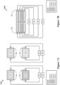
- FIG. 7B shows another sensor array 700B, according to some implementations.
- the sensor array 700B includes a plurality of carbon-based sensors 701-704 stacked on top of one another in a vertical or stacked arrangement.
- the sensors 701-704 may be examples of the sensors 120 of Figures 1-3 and Figures 5-6 .
- the sensors 701-704 may be examples of the sensors 434 of Figure 4 .
- the sensors 701-704 (and their respective sensing materials) can be sequentially deposited upon one another to form the stacked array.
- separators (not shown for simplicity) can be provided between the sensors 701-704.
- the sensors 701-704 may be functionalized with different materials and/or may include different types of carbon-based sensing materials that can be printed in successive layers onto a substrate or label.
- analyte sensors As the demand for low-cost analyte sensors continues to increase, it is increasingly important to reduce or even eliminate the need for electronic components in analyte sensors. For example, the high cost of electronic components typically found in conventional analyte sensors render their widespread deployment in shipping containers, packages, and envelopes impractical. As such, some implementations of the subject matter disclosed herein may provide a cost-effective solution to the long-standing problem of monitoring large numbers of shipping containers, packages, and envelopes for the presence of harmful chemicals and gases such as, for example, the various analytes described herein.
- Figure 7C is an illustration 700C depicting an ink-jet or bubble-jet print head 720 printing various sensing devices disclosed herein onto the surface of a shipping container, package, or envelope, according to some implementations. Specifically, the illustration 700C depicts a process by which multiple layers of different carbon-based sensing materials 711-714 can be printed onto a substrate 710.
- the print head 720 can print a first layer 711 of carbon-based sensing materials onto the substrate 710 using a first carbon-based ink 721, can print a second layer 712 of carbon-based sensing materials onto the substrate 710 using a second carbon-based ink 722, can print a third layer 713 of carbon-based sensing materials onto the substrate 710 using a third carbon-based ink 723, and can print a fourth layer 714 of carbon-based sensing materials onto the substrate 710 using a fourth carbon-based ink 724.
- the carbon-based inks 721-724 may be different from one another, for example, such that the resulting sensing material layers 711-714 are configured to react with and/or detect different analytes or different group of analytes.
- the print head 720 can also print electrodes E1-E4 for the different sensing material layers 711-714, respectively, using an ohmic-based ink 725.
- Ohmic contacts can be printed onto the substrate 710 and/or portions of the sensing material layers 711-714 using multiple passes of the multi-jet print head 720.
- the sensing device may include vias through which the resulting electrodes E1-E4 can be accessed. In other implementations, other suitable mechanisms can be used to provide ohmic contacts for the electrodes E1-E4.
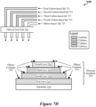
- Figure 7D is an illustration 700D depicting the print head 720 printing various sensing devices disclosed herein onto the surface of a shipping container, package, or envelope, according to other implementations.
- the illustration 700D depicts a process by which multiple layers of different carbon-based sensing materials 711-714 can be printed onto a substrate 710 in a pyramid arrangement.
- the illustration 700D also depicts ohmic contacts 705 printed on the sensing material layers 711-714 using an ohmic-based ink 725.
- the different sizes and different exposed surface areas of the sensing material layers 711-714 may cause the respective sensors to have different electrical and/or chemical characteristics, which in turn may configured the respective sensors to react with and/or detect different types of analytes.
- Table 1 Components Tuning Sensitivity Calibration Different carbon types and/or different carbon decorations Select carbon functionalization materials to detect selected analytes Surface area of carbon-based sensor Response of the selected carbon functionalization materials to the selected analytes Physical dimensions of the sensing material Select size and/or aspect ratio of exposed portion of sensor Surface area of carbon-based sensor Sensitivity is based on physical dimensions and characteristics of carbon-based sensor Adjacency or proximity to other carbon-based sensing materials Select distance between sensors to reduce overlapping response signals Select distance between sensors to reduce overlapping response signals Calibrate based on test sample over a range conditions Different permittivity of the different materials Tune permittivity based on sensor material/functionaliza tion Select distance between sensors to reduce Calibrate based on test sample over a range conditions overlapping response signals
- the permittivity of carbon-based sensing materials described herein can be modified by exposing the materials to ultraviolet (UV) radiation.
- FIG. 7E is an illustration 700E depicting UV radiation emitted towards the sensor 701.
- a UV beam source 753 may be used to shower the sensor 701 with UV radiation.
- the power and wavelength of the UV radiation can be controlled by a power control unit 751 and a wavelength control unit 752, respectively.
- adjusting the power level and/or wavelength of UV radiation can change the permittivity of each of the sensing material layers 711-714. That is, after bombarded with the UV radiation, each of the sensing material layers 711-714 may resonate at a different frequency.
- the different permittivity of the sensing material layers 711-714 may collectively a permittivity gradient 725.
- the permittivity gradient 725 may correspond to a stair shaped gradient 761, a linearly shaped gradient 762, or a curvilinearly shaped gradient 763.
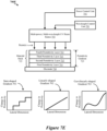
- Figure 8 shows a flow chart 800 depicting an example operation for fabricating at least some of the sensing devices disclosed herein, according to some implementations.
- the permittivity of a carbon-based sensing material can be altered to cause a particular resonance signature in the carbon-based sensing material when exposed to certain analytes.
- different portions of the carbon-based sensing material may be configured to have different permittivity values specifically selected to cause particular resonance frequencies and/or or resonance signatures.
- a first portion of the carbon-containing material with a first permittivity that is tuned to resonate with a particular resonance signature when the first portion of the carbon-containing material has imbibed a first analyte of interest
- a second portion of the carbon-containing material has a second permittivity that is tuned to resonate with a particular resonance signature when the second portion of the carbon-containing material has imbibed a second analyte of interest.
- Formation of different portions of the carbon-containing material having different permittivity values can be accomplished using a combination of masking and UV treatments.
- a carbon-containing material is deposited onto a substrate or electrode 811.
- a UV-opaque mask is deposited or printed on top the carbon-containing material.
- the carbon-containing material is activated, for example, via bombardment by UV photons. This results in a first portion 812 1 of the carbon-containing material having a first permittivity, and a second portion 812 2 of the carbon-containing material having a second permittivity different than the first permittivity.
- the mask can be washed away, ablated, or otherwise removed.
- Two or more of the resulting analyte-sensing devices can be used as a multi-element, multi-analyte sensor and/or as a high-sensitivity analyte sensor.
- the resulting analyte-sensing devices can be exposed to an additional bombardment of UV photons at block 810, for example, to further alter portions of the carbon-containing material previously beneath the UV-opaque mask.
- FIG. 9 shows another sensor array 900, according to some implementations.
- the sensor array 900 includes a plurality of layers 911-914 of individually-functionalized carbon-containing materials. As shown, the layers 911-914 are successively disposed to form a stack of layers, with the first layer 911 disposed on the substrate 910. Each layer is formed of a corresponding individually-functionalized carbon-containing matrix (such as carbon matrix 1, carbon matrix2, carbon matrix3, carbon matrix4), wherein each individually-functionalized carbon-containing matrix includes a respective additive A-D).
- the combinations of carbon-containing matrices and additive may be selected based on the particular combination's sensitivity to a particular analyte of interest.
- the different layers can be deposited using any known technique. Furthermore, each of the different layers can be configured to be of a particular thickness. Strictly as one example, and as shown, a first deposited layer can have a first thickness 924 in a first range (such as 10 nm-100 nm, whereas another deposited layer can have a thickness in a different range (such as 500 nm-1,000 nm), and so on.
- the particular thickness of a particular layer can be selected based upon any combination of:
- the open pore structure of carbon-based sensing materials disclosed herein may allow certain analytes to more easily penetrate the materials and/or to more easily interact with carbon matrices within the materials. As such, these open pores may increase the sensitivity of sensors disclosed herein to analytes than conventional analyte detection systems.
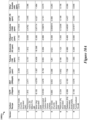
- FIG 10A shows an example sensor configuration 1000A, according to some implementations.
- the sensor configuration 1000A includes mappings between sensors of an analyte detection system and various analytes, according to some implementations.
- the 3D graphene-based sensing materials of the carbon-based sensors 120 of Figure 1 may be or include the carbon recipes shown in the sensor configuration 1000A. That is, in a configuration in which the sensor array 120 includes 8 carbon-based sensors 120, each sensor may have a corresponding carbon recipe as shown by the example sensor configuration 1000A.
- a first sensor may be cobalt oxide (Co 2 O 3 ) decorated CNO and produce a percentage change in current (% ⁇ I) over initial current (I 0 ) and/or percentage increase in measured impedance of 9.26244%, and so on.
- the carbon recipes of the sensor configuration 1000A may be used to configure the carbon-based sensors to detect and identify different analytes (such as TATP, DNT, H 2 S, and so on), even at relatively low concentration levels, based on their respective chemical fingerprints.
- the sensing devices disclosed herein may be able to detect relatively low concentrations of analytes and/or other chemical threat agents, even in the presence of common interferents.
- Figure 10B shows another example sensor configuration 1000B, according to some implementations.
- the sensor configuration 1000B may be similar to the sensor configuration 1000A of Figure 10A , for example, such that:
- Example gas mixtures used to produce Carbon #19 and/or the silver-decorated DXR carbons substantially shown in Figures 11D and 11G may include the following steps:
- Carbon # 16 corresponding to "DXR" (as characterized by Figures 5A and/or 5B) type or configuration carbons produced in a microwave reactor; iron(II) acetate, a white solid particulate substance suspended in carrier gas to create iron acetate vapor, is flowed into the microwave reactor at a ratio of approximately 65.17 wt% corresponding to 34.83 wt% carbon (referring to carbon in DXR form), resulting in the functionalization of active sites on the DXR configuration carbons with silver as substantially shown in Figure 11D (in undecorated form) and/or in Figure 11G (showing actual decoration with cobalt instead of iron).
- Example gas mixtures used to produce Carbon #16 and/or the iron-decorated DXR carbons substantially shown in Figures 11D and 11G may include the following steps:
- Carbon # 1 corresponding to "Anvel” (as characterized by Figure 7C ) type or configuration carbons produced in a microwave reactor; platinum(II) bis(acetylacetonate), a coordination compound with the formula Pt(O 2 C 5 H 7 ) 2 , abbreviated Pt 2 , is flowed as a particulate dispersed in carrier gas to create platinum(II) bis(acetylacetonate) vapor, is flowed into the microwave reactor at a ratio of approximately 76.62 wt% corresponding to 23.38 wt% carbon (referring to carbon in Anvel form), resulting in the functionalization of active sites on the Anvel configuration carbons with platinum as substantially shown in Figure 11C (in undecorated form); suitable gas mixtures used to produce Carbon #1 and/or the undecorated Anvel carbons substantially shown in Figures 11C may include the following steps:
- Example gas mixtures used to produce Carbon #6 and/or the palladium-decorated Anvel carbons substantially shown in Figure 11C may include the following steps:
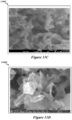
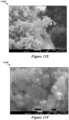
- Figures 11A-11G show illustrations of various structured carbon materials that can be used in the sensing devices disclosed herein, according to some implementations.
- Figure 11A shows a micrograph 1100A of thermogravimetric (TG) carbons, according to various implementations.
- Figure 11B shows a micrograph 1100B of undecorated CNOs, according to various implementations.
- Figure 11C shows a micrograph 1100C of Anvel carbons, according to various implementations.
- Figure 11D shows a micrograph 1100D of DXR carbons, according to various implementations.
- Figure 11E shows a micrograph 1100E of cobalt decorated CNOs at a magnification level of 15,000x, according to various implementations.
- Figure 11F shows a micrograph 1100F of cobalt decorated CNOs at a magnification level of 100,000x, according to various implementations.
- Figure 11G shows a micrograph 1100G of a cobalt decorated DXR carbons, according to various implementations.
- the 3D graphene sensing materials disclosed by the present implementations may be designed to have a convoluted 3D structure to prevent graphene restacking, avoiding several drawbacks of using 2D graphene as a sensing material. This process also increases the areal density of the materials, yielding higher analyte adsorption sites per unit area, thereby improving chemical sensitivity, as made possible by a corresponding library of carbon allotropes used to customize the sensor arrays disclosed herein to chemically fingerprint leaked analytes for multiple applications.
- the structured carbon materials shown in Figures 11A-11G may be produced using flow-through type microwave plasma reactors configured to create pristine 3D graphene particles continuously from a hydrocarbon gas at near atmospheric pressures. Operationally, as the hydrocarbon flows through a relatively hot zone of a plasma reactor, free carbon radicals may be formed that flow further down the length of the reactor into the growth zone where 3D carbon particulates (based on multiple 2D graphenes joined together) are formed and collected as fine powders.
- the density and composition of the free-radical carbon-inclusive gaseous species may be tuned by gas chemistry and microwave (MW) power levels.
- these reactors may produce carbons with a wide, yet tunable, range of morphologies, crystalline order, and sizes (and distributions).
- possible sizes and distributions may range from flakes (few 100 nm to ⁇ m wide and few nm thin) to spherical particles (10s of nm in diameter) to graphene clusters (10s of ⁇ m).
- the 3D nature of the materials prevents agglomeration effectively allowing for the materials to be disseminated as un-agglomerated particles.
- highly responsive and selective sensing materials can be produced.
- Graphene an atomically thin two dimensional (2D) material, has many advantageous properties for sensing, including outstanding chemical and mechanical strength, high carrier mobility, high electrical conductivity, high surface area, and gate-tunable carrier density.
- the 3D graphenes of the presently disclosed graphenes may be functionalized with various reactive materials in such a manner that the binding of target molecules and the carbon may be optimized.
- This functionalization step along with the ability to measure the complex impedance of the exposed sensor may be critical for efficient and selective detection of analytes.
- different metal nanoparticles or metal oxide nanoparticles may be decorated on the surface of 3D graphenes to selectively detect hydrogen peroxide (a TATP degradation product) as peroxides are known to react with different metals.
- nanoparticle decorated graphene structures may act synergistically to offer desirable and advantageous properties for sensing applications.
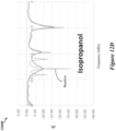
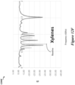
- Figures 12A-12F show example frequency responses of resonance impedance sensors to various analytes, according to some implementations.
- Figure 12A shows an example frequency response 1200A of sensors 120 to alongside a baseline or reference frequency response.
- Figure 12A shows an example frequency response 1200A of sensors 120 to acetone alongside a baseline or reference frequency response.
- Figure 12B shows an example frequency response 1200B of sensors 120 to acetonitrile alongside a baseline or reference frequency response.
- Figure 12C shows an example frequency response 1200C of sensors 120 to Ethanol alongside a baseline or reference frequency response.
- Figure 12D shows an example frequency response 1200A of sensors 120 to isopropanol alongside a baseline or reference frequency response.
- Figure 12E shows an example frequency response 1200E of sensors 120 to water alongside a baseline or reference frequency response.
- Figure 12F shows an example frequency response 1200F of sensors 120 to xylenes alongside a baseline or reference frequency response.
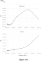
- Figure 13A is a graph 1300A depicting the real (Z') impedance component of example frequency responses of sensors 120 to Acetone, Ethanol (EtOH), water, and hydrogen peroxide (H 2 O 2 ) alongside a baseline or reference frequency response, according to some implementations.
- Figure 13B is a graph 1300B depicting the imaginary (Z") impedance component of example frequency responses of sensors 120 to Acetone, Ethanol (EtOH), water, and hydrogen peroxide (H 2 O 2 ) alongside a baseline or reference frequency response, according to some implementations.
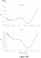
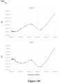
- Figure 14A shows an example frequency response of sensors 120 to hydrogen peroxide alongside a baseline or reference frequency response, according to some implementations.
- Figure 14B shows example frequency responses of sensors 120 to acetone and water, according to some implementations.
- Figure 14C shows example frequency responses to ethanol and ammonia, according to some implementations.
- a phrase referring to "at least one of” or “one or more of” a list of items refers to any combination of those items, including single members.
- "at least one of: a, b, or c” is intended to cover the possibilities of: a only, b only, c only, a combination of a and b, a combination of a and c, a combination of b and c, and a combination of a and b and c.
Landscapes
- Chemical & Material Sciences (AREA)
- Engineering & Computer Science (AREA)
- Health & Medical Sciences (AREA)
- Life Sciences & Earth Sciences (AREA)
- Physics & Mathematics (AREA)
- Organic Chemistry (AREA)
- Nanotechnology (AREA)
- Pathology (AREA)
- Biochemistry (AREA)
- General Health & Medical Sciences (AREA)
- General Physics & Mathematics (AREA)
- Immunology (AREA)
- Analytical Chemistry (AREA)
- Electrochemistry (AREA)
- Chemical Kinetics & Catalysis (AREA)
- Inorganic Chemistry (AREA)
- Materials Engineering (AREA)
- Combustion & Propulsion (AREA)
- Food Science & Technology (AREA)
- Medicinal Chemistry (AREA)
- Spectroscopy & Molecular Physics (AREA)
- Investigating Or Analyzing Materials By The Use Of Electric Means (AREA)
- Investigating Or Analyzing Materials By The Use Of Fluid Adsorption Or Reactions (AREA)
- Measurement Of The Respiration, Hearing Ability, Form, And Blood Characteristics Of Living Organisms (AREA)
Applications Claiming Priority (5)
| Application Number | Priority Date | Filing Date | Title |
|---|---|---|---|
| US202062979095P | 2020-02-20 | 2020-02-20 | |
| US16/887,293 US11137368B2 (en) | 2018-01-04 | 2020-05-29 | Resonant gas sensor |
| US202063088541P | 2020-10-07 | 2020-10-07 | |
| PCT/US2021/019110 WO2021168444A1 (en) | 2020-02-20 | 2021-02-22 | Analyte sensing device |
| EP21757136.3A EP4107518A4 (de) | 2020-02-20 | 2021-02-22 | Analyterfassungsvorrichtung |
Related Parent Applications (1)
| Application Number | Title | Priority Date | Filing Date |
|---|---|---|---|
| EP21757136.3A Division EP4107518A4 (de) | 2020-02-20 | 2021-02-22 | Analyterfassungsvorrichtung |
Publications (2)
| Publication Number | Publication Date |
|---|---|
| EP4491572A2 true EP4491572A2 (de) | 2025-01-15 |
| EP4491572A3 EP4491572A3 (de) | 2025-03-19 |
Family
ID=77391343
Family Applications (3)
| Application Number | Title | Priority Date | Filing Date |
|---|---|---|---|
| EP24215739.4A Pending EP4491573A3 (de) | 2020-02-20 | 2021-02-22 | Analyterfassungsvorrichtung |
| EP21757136.3A Pending EP4107518A4 (de) | 2020-02-20 | 2021-02-22 | Analyterfassungsvorrichtung |
| EP24215315.3A Pending EP4491572A3 (de) | 2020-02-20 | 2021-02-22 | Analyterfassungsvorrichtung |
Family Applications Before (2)
| Application Number | Title | Priority Date | Filing Date |
|---|---|---|---|
| EP24215739.4A Pending EP4491573A3 (de) | 2020-02-20 | 2021-02-22 | Analyterfassungsvorrichtung |
| EP21757136.3A Pending EP4107518A4 (de) | 2020-02-20 | 2021-02-22 | Analyterfassungsvorrichtung |
Country Status (6)
| Country | Link |
|---|---|
| EP (3) | EP4491573A3 (de) |
| JP (1) | JP7722999B2 (de) |
| KR (1) | KR20220143820A (de) |
| CN (1) | CN115836216B (de) |
| IL (1) | IL294954B1 (de) |
| WO (1) | WO2021168444A1 (de) |
Families Citing this family (1)
| Publication number | Priority date | Publication date | Assignee | Title |
|---|---|---|---|---|
| WO2023122668A1 (en) | 2021-12-22 | 2023-06-29 | Nabors Energy Transition Solutions Llc | Sulfur doped carbon-based nanomaterial and methods of forming the same |
Family Cites Families (23)
| Publication number | Priority date | Publication date | Assignee | Title |
|---|---|---|---|---|
| US6720866B1 (en) | 1999-03-30 | 2004-04-13 | Microchip Technology Incorporated | Radio frequency identification tag device with sensor input |
| US7171312B2 (en) * | 2002-07-19 | 2007-01-30 | Smiths Detection, Inc. | Chemical and biological agent sensor array detectors |
| US7040139B2 (en) | 2003-06-10 | 2006-05-09 | Smiths Detection Inc. | Sensor arrangement |
| KR100721261B1 (ko) * | 2005-11-30 | 2007-05-25 | 전자부품연구원 | 마이크로 가스 센서, 그의 제조 방법, 그의 패키지 및 그패키지의 제조 방법 |
| US20080135614A1 (en) | 2006-06-30 | 2008-06-12 | The Penn State Research Foundation | Passive detection of analytes |
| US20100134286A1 (en) | 2008-12-01 | 2010-06-03 | General Electric Company | Radio frequency based sensors employing analyte recognition element |
| US9052263B2 (en) | 2009-04-15 | 2015-06-09 | General Electric Company | Methods for analyte detection |
| US8951473B2 (en) * | 2008-03-04 | 2015-02-10 | Massachusetts Institute Of Technology | Devices and methods for determination of species including chemical warfare agents |
| WO2009144725A1 (en) * | 2008-05-29 | 2009-12-03 | Technion Research And Development Foundation Ltd. | Carbon nanotube structures in sensor apparatuses for analyzing biomarkers in breath samples |
| KR101203181B1 (ko) * | 2010-03-05 | 2012-11-20 | 전자부품연구원 | 플렉서블 가스 센서 어레이 및 그 제조 방법 |
| EP2803984B1 (de) * | 2012-01-13 | 2017-09-13 | The University of Tokyo | Gassensor |
| JP5495077B2 (ja) | 2012-05-01 | 2014-05-21 | 謙治 佐藤 | 無線タグ型センサ |
| US9494541B2 (en) * | 2012-07-05 | 2016-11-15 | General Electricity Company | Sensors for gas dosimetry |
| US9791401B2 (en) * | 2012-12-07 | 2017-10-17 | Sarissa Biomedical Limited | Device including biosensor and holder |
| WO2015112213A2 (en) | 2013-10-30 | 2015-07-30 | Massachusetts Institute Of Technology | Chemical and physical sensing with a reader and rfid tags |
| JP2018517954A (ja) | 2015-04-10 | 2018-07-05 | シン フィルム エレクトロニクス エーエスエー | 開封された、または損なわれた容器を検出するための複数の有効な状態を有するセンサベースのnfc/rf機構、ならびにそれらを製造および使用する方法 |
| CN108366868B (zh) | 2015-12-02 | 2021-08-10 | 株式会社村田制作所 | 带水分检测用rfid标签的卫生用品 |
| US10054543B2 (en) * | 2016-02-23 | 2018-08-21 | The United States Of America, As Represented By The Secretary Of The Army | Multi-dimensional cross-reactive array for chemical sensing |
| EP3260860A1 (de) * | 2016-06-23 | 2017-12-27 | Nokia Technologies Oy | Vorrichtung mit einem graphenbasierten sensor und verfahren zur verwendung dieser vorrichtung |
| CN106970124B (zh) * | 2017-02-24 | 2019-04-19 | 浙江大学 | 一种基于移动终端的用于生化检测的nfc标签传感器系统及其应用 |
| US10719755B2 (en) * | 2017-03-31 | 2020-07-21 | Massachusetts Institute Of Technology | Wireless oxygen dosimeter |
| US20190003977A1 (en) * | 2017-06-30 | 2019-01-03 | Avago Technologies General Ip (Singapore) Pte. Ltd. | Analyte sensing device |
| WO2019136181A1 (en) * | 2018-01-04 | 2019-07-11 | Lyten, Inc. | Resonant gas sensor |
-
2021
- 2021-02-22 EP EP24215739.4A patent/EP4491573A3/de active Pending
- 2021-02-22 KR KR1020227026820A patent/KR20220143820A/ko not_active Ceased
- 2021-02-22 WO PCT/US2021/019110 patent/WO2021168444A1/en not_active Ceased
- 2021-02-22 JP JP2022548776A patent/JP7722999B2/ja active Active
- 2021-02-22 EP EP21757136.3A patent/EP4107518A4/de active Pending
- 2021-02-22 CN CN202180011944.7A patent/CN115836216B/zh active Active
- 2021-02-22 EP EP24215315.3A patent/EP4491572A3/de active Pending
-
2022
- 2022-07-21 IL IL294954A patent/IL294954B1/en unknown
Also Published As
| Publication number | Publication date |
|---|---|
| EP4107518A1 (de) | 2022-12-28 |
| EP4491572A3 (de) | 2025-03-19 |
| JP7722999B2 (ja) | 2025-08-13 |
| IL294954B1 (en) | 2026-02-01 |
| KR20220143820A (ko) | 2022-10-25 |
| EP4491573A3 (de) | 2025-03-19 |
| EP4491573A2 (de) | 2025-01-15 |
| WO2021168444A1 (en) | 2021-08-26 |
| JP2023515374A (ja) | 2023-04-13 |
| CN115836216B (zh) | 2026-01-23 |
| IL294954A (en) | 2022-09-01 |
| EP4107518A4 (de) | 2024-03-06 |
| CN115836216A (zh) | 2023-03-21 |
Similar Documents
| Publication | Publication Date | Title |
|---|---|---|
| US11913901B2 (en) | Analyte sensing device | |
| US11988628B2 (en) | Container including analyte sensing device | |
| US12119462B2 (en) | Sensing device for detecting analytes in batteries | |
| US11137368B2 (en) | Resonant gas sensor | |
| US20210181146A1 (en) | Sensing device for detecting analytes in packages | |
| US10955378B2 (en) | Resonant gas sensor | |
| Reddy et al. | Recent material advances and their mechanistic approaches for room temperature chemiresistive gas sensors | |
| Chen et al. | A nanoelectronic nose: a hybrid nanowire/carbon nanotube sensor array with integrated micromachined hotplates for sensitive gas discrimination | |
| US20160231267A1 (en) | Devices and methods including a preconcentrator material for detection of analytes | |
| CN111051868B (zh) | 甲醛检测传感器和使用其的系统 | |
| EP4491572A2 (de) | Analyterfassungsvorrichtung | |
| US11688895B1 (en) | Battery safety system for detecting analytes | |
| US20250189474A1 (en) | Analyte sensing device | |
| KR20260036628A (ko) | 분석물 감지 장치 | |
| WO2025122846A1 (en) | Analyte sensing device | |
| KR20240163604A (ko) | 분석물을 검출하기 위한 배터리 안전 시스템 | |
| Laera et al. | Flexible Humidity Sensor Based on Chemically Reduced Graphene Oxide. Chemosensors 2024, 12, 245 | |
| Dhall et al. | Hydrogen Sensing of NiO and Cu2O/Multiwalled Carbon Nanotubes Nanostructures at Room Temperature | |
| Valt | 2D materials for room-temperature chemoresistive gas sensing |
Legal Events
| Date | Code | Title | Description |
|---|---|---|---|
| PUAI | Public reference made under article 153(3) epc to a published international application that has entered the european phase |
Free format text: ORIGINAL CODE: 0009012 |
|
| STAA | Information on the status of an ep patent application or granted ep patent |
Free format text: STATUS: THE APPLICATION HAS BEEN PUBLISHED |
|
| AC | Divisional application: reference to earlier application |
Ref document number: 4107518 Country of ref document: EP Kind code of ref document: P |
|
| AK | Designated contracting states |
Kind code of ref document: A2 Designated state(s): AL AT BE BG CH CY CZ DE DK EE ES FI FR GB GR HR HU IE IS IT LI LT LU LV MC MK MT NL NO PL PT RO RS SE SI SK SM TR |
|
| REG | Reference to a national code |
Ref country code: DE Ref legal event code: R079 Free format text: PREVIOUS MAIN CLASS: C01B0032194000 Ipc: G01N0027414000 |
|
| PUAL | Search report despatched |
Free format text: ORIGINAL CODE: 0009013 |
|
| AK | Designated contracting states |
Kind code of ref document: A3 Designated state(s): AL AT BE BG CH CY CZ DE DK EE ES FI FR GB GR HR HU IE IS IT LI LT LU LV MC MK MT NL NO PL PT RO RS SE SI SK SM TR |
|
| RIC1 | Information provided on ipc code assigned before grant |
Ipc: C01B 32/194 20170101ALI20250213BHEP Ipc: C01B 32/18 20170101ALI20250213BHEP Ipc: G01N 27/12 20060101ALI20250213BHEP Ipc: G01N 27/02 20060101ALI20250213BHEP Ipc: B01J 20/28 20060101ALI20250213BHEP Ipc: G01N 33/00 20060101ALI20250213BHEP Ipc: C01B 32/182 20170101ALI20250213BHEP Ipc: G01N 27/414 20060101AFI20250213BHEP |
|
| P01 | Opt-out of the competence of the unified patent court (upc) registered |
Free format text: CASE NUMBER: APP_12062/2025 Effective date: 20250312 |
|
| STAA | Information on the status of an ep patent application or granted ep patent |
Free format text: STATUS: REQUEST FOR EXAMINATION WAS MADE |
|
| 17P | Request for examination filed |
Effective date: 20250915 |
|
| STAA | Information on the status of an ep patent application or granted ep patent |
Free format text: STATUS: EXAMINATION IS IN PROGRESS |
|
| 17Q | First examination report despatched |
Effective date: 20260219 |