EP4491552B1 - Card feeder for a card processing machine - Google Patents
Card feeder for a card processing machine Download PDFInfo
- Publication number
- EP4491552B1 EP4491552B1 EP24186956.9A EP24186956A EP4491552B1 EP 4491552 B1 EP4491552 B1 EP 4491552B1 EP 24186956 A EP24186956 A EP 24186956A EP 4491552 B1 EP4491552 B1 EP 4491552B1
- Authority
- EP
- European Patent Office
- Prior art keywords
- ballast
- cards
- card
- slider
- support
- Prior art date
- Legal status (The legal status is an assumption and is not a legal conclusion. Google has not performed a legal analysis and makes no representation as to the accuracy of the status listed.)
- Active
Links
Images


Classifications
-
- B—PERFORMING OPERATIONS; TRANSPORTING
- B65—CONVEYING; PACKING; STORING; HANDLING THIN OR FILAMENTARY MATERIAL
- B65H—HANDLING THIN OR FILAMENTARY MATERIAL, e.g. SHEETS, WEBS, CABLES
- B65H1/00—Supports or magazines for piles from which articles are to be separated
- B65H1/04—Supports or magazines for piles from which articles are to be separated adapted to support articles substantially horizontally, e.g. for separation from top of pile
- B65H1/06—Supports or magazines for piles from which articles are to be separated adapted to support articles substantially horizontally, e.g. for separation from top of pile for separation from bottom of pile
-
- B—PERFORMING OPERATIONS; TRANSPORTING
- B65—CONVEYING; PACKING; STORING; HANDLING THIN OR FILAMENTARY MATERIAL
- B65H—HANDLING THIN OR FILAMENTARY MATERIAL, e.g. SHEETS, WEBS, CABLES
- B65H1/00—Supports or magazines for piles from which articles are to be separated
- B65H1/08—Supports or magazines for piles from which articles are to be separated with means for advancing the articles to present the articles to the separating device
- B65H1/10—Supports or magazines for piles from which articles are to be separated with means for advancing the articles to present the articles to the separating device comprising weights
-
- B—PERFORMING OPERATIONS; TRANSPORTING
- B65—CONVEYING; PACKING; STORING; HANDLING THIN OR FILAMENTARY MATERIAL
- B65H—HANDLING THIN OR FILAMENTARY MATERIAL, e.g. SHEETS, WEBS, CABLES
- B65H3/00—Separating articles from piles
- B65H3/02—Separating articles from piles using friction forces between articles and separator
- B65H3/06—Rollers or like rotary separators
- B65H3/063—Rollers or like rotary separators separating from the bottom of pile
-
- B—PERFORMING OPERATIONS; TRANSPORTING
- B65—CONVEYING; PACKING; STORING; HANDLING THIN OR FILAMENTARY MATERIAL
- B65H—HANDLING THIN OR FILAMENTARY MATERIAL, e.g. SHEETS, WEBS, CABLES
- B65H3/00—Separating articles from piles
- B65H3/46—Supplementary devices or measures to assist separation or prevent double feed
- B65H3/54—Pressing or holding devices
-
- B—PERFORMING OPERATIONS; TRANSPORTING
- B65—CONVEYING; PACKING; STORING; HANDLING THIN OR FILAMENTARY MATERIAL
- B65H—HANDLING THIN OR FILAMENTARY MATERIAL, e.g. SHEETS, WEBS, CABLES
- B65H2301/00—Handling processes for sheets or webs
- B65H2301/40—Type of handling process
- B65H2301/42—Piling, depiling, handling piles
- B65H2301/422—Handling piles, sets or stacks of articles
- B65H2301/4223—Pressing piles
-
- B—PERFORMING OPERATIONS; TRANSPORTING
- B65—CONVEYING; PACKING; STORING; HANDLING THIN OR FILAMENTARY MATERIAL
- B65H—HANDLING THIN OR FILAMENTARY MATERIAL, e.g. SHEETS, WEBS, CABLES
- B65H2402/00—Constructional details of the handling apparatus
- B65H2402/40—Details of frames, housings or mountings of the whole handling apparatus
- B65H2402/44—Housings
- B65H2402/441—Housings movable for facilitating access to area inside the housing, e.g. pivoting or sliding
-
- B—PERFORMING OPERATIONS; TRANSPORTING
- B65—CONVEYING; PACKING; STORING; HANDLING THIN OR FILAMENTARY MATERIAL
- B65H—HANDLING THIN OR FILAMENTARY MATERIAL, e.g. SHEETS, WEBS, CABLES
- B65H2402/00—Constructional details of the handling apparatus
- B65H2402/40—Details of frames, housings or mountings of the whole handling apparatus
- B65H2402/45—Doors
-
- B—PERFORMING OPERATIONS; TRANSPORTING
- B65—CONVEYING; PACKING; STORING; HANDLING THIN OR FILAMENTARY MATERIAL
- B65H—HANDLING THIN OR FILAMENTARY MATERIAL, e.g. SHEETS, WEBS, CABLES
- B65H2405/00—Parts for holding the handled material
- B65H2405/10—Cassettes, holders, bins, decks, trays, supports or magazines for sheets stacked substantially horizontally
- B65H2405/11—Parts and details thereof
- B65H2405/111—Bottom
- B65H2405/1115—Bottom with surface inclined, e.g. in width-wise direction
- B65H2405/11152—Bottom with surface inclined, e.g. in width-wise direction with surface inclined downwardly in transport direction
-
- B—PERFORMING OPERATIONS; TRANSPORTING
- B65—CONVEYING; PACKING; STORING; HANDLING THIN OR FILAMENTARY MATERIAL
- B65H—HANDLING THIN OR FILAMENTARY MATERIAL, e.g. SHEETS, WEBS, CABLES
- B65H2701/00—Handled material; Storage means
- B65H2701/10—Handled articles or webs
- B65H2701/19—Specific article or web
- B65H2701/1914—Cards, e.g. telephone, credit and identity cards
Definitions
- the present invention relates to a card feeder for a card processing machine, as well as a processing machine including such a card feeder.
- processing machines designed to process plastic cards, such as bank cards.
- a processing machine is, for example, a printer which prints a pattern on the card, or an encoding machine which encodes a chip on the card.
- the processing machine is equipped with a processing module which acts on the card.
- such a card feeder includes a reservoir where the cards are stacked on top of one another and a separation system which picks the cards one after another while separating them.
- Different separation systems have been implemented, but they are not always satisfactory, and it is therefore necessary to find a card feeder with a different separation system. Further relevant prior art is described in EP 2125 383 B1 disclosing the preamble of claim 1,
- An object of the present invention is to provide a card feeder for a card processing machine which has means for ensuring good support on a drive roll.
- a card feeder for a processing machine including:
- the ballast is mounted movable in rotation about a tilting axis parallel to the axis of the separation roll, the tilting axis is arranged so that the center of gravity of the ballast is vertically above the tilting axis and horizontally between the tilting axis and the reservoir, when the ballast is in the stowed position, and the return system is gravity.
- the transmission system includes:
- the invention also proposes a card processing machine including a card feeder according to one of the preceding variants, a processing module, and a transport system including means for moving the cards from the card feeder to the processing module.
- a processing machine 100 including a card feeder 150 according to the invention where the processing machine 100 is in the position of use, i.e., as shown in Fig. 1 .
- the processing machine 100 includes a card feeder 150 according to the invention, a processing module 102, and a transport system 104 which includes means for moving the cards from the card feeder 150 to the processing module 102, where the means conventionally include rolls which pinch the cards and motors which drive the rolls in rotation.
- the processing module 102 is downstream of the card feeder 150 with respect to the direction of movement D of the cards by the transport system 104.
- the processing module 102 is a printer or an encoding module, etc.
- the processing module 102 and the transport system 104 will not be described in more detail because they can take on any form known to a person skilled in the art.
- Figs. 2 to 6 show the card feeder 150 from different angles.
- the card feeder 150 includes a frame 152 which is secured to the frame of the processing machine 100.
- the frame 152 of the card feeder 150 may be a portion of the frame of the processing machine 100 or an attached and fixed element.
- the card feeder 150 includes a reservoir 156 which is herein delimited by three vertical walls 156a-c, namely a back wall 156c and two lateral walls 156a-b arranged on either side of the back wall 156c. These vertical walls 156a-c are secured to the frame 152 and thus form, when viewed from above, a U-like shape, where the lateral walls 156a-b form the branches of the U-like shape and where the back wall 156c forms the bottom of the U-like shape.
- the reservoir 156 has a tray 154 which forms the base of the reservoir 156 and above which a support 154a is provided which serves as a support for a stack 52 of cards, such as plastic cards, 50 placed thereon.
- the stack 52 of cards 50 is formed by a vertical stack of cards 50 which are placed flat on top of one another and over the support 154a.
- the stack 52 of cards 50 is arranged between the vertical walls 156a-c and over the support 154a.
- the card feeder 150 also includes a door 162 which is movably mounted on the frame 152 and which forms the fourth wall of the reservoir 156.
- the door 162 is movably mounted on the frame 152 between an open position, enabling access to the inside of the reservoir 156 and the deposition of cards 50 on the support 154a, and a closed position, preventing access to the reservoir 156 while enclosing the cards 50 in the reservoir 156, and vice versa.
- the door 162 closes the U-like shape formed by the vertical walls 156a-c.
- the door 162 is movable in rotation about a door axis 162a, herein vertical.
- the card feeder 150 also includes a separation system 158 which is arranged so as to separate the cards 50 stored in the reservoir 156 from each other, while moving them successively through the bottom wall 156c according to a drive direction F which is then extended by direction of movement D.
- a separation system 158 which is arranged so as to separate the cards 50 stored in the reservoir 156 from each other, while moving them successively through the bottom wall 156c according to a drive direction F which is then extended by direction of movement D.
- the separation system 158 includes a separation roll 158a which is arranged at the level of the tray 154 according to a direction transverse to the drive direction F.
- the separation roll 158a is mounted movable in rotation on the frame 152 about its axis 158b. Thus, the cards 50 are in contact with the top of the separation roll 158a and the top of the support 154a.
- the separation system 158 also includes a drive system, such as a motor, mounted on the frame 152, which is arranged so as to drive the separation roll 158a in rotation in the direction of the arrow R to drive the card 50 following the drive direction F.
- the processing machine 100 or the card feeder 150 includes a control unit arranged so as to control the drive system according to the needs.
- the stack 52 of cards 50 rests on the separation roll 158a and the support 154a, and the separation is thus performed from below the stack 52, i.e., the separation roll 158a drives the card 50 which is the lowest, i.e., which rests on the separation roll 158a and the support 154a, to pull it out of the stack 52 and move it following the drive direction F through the bottom wall 156c through a window 164 that the bottom wall 156c has for this purpose.
- the window 164 is sized in height to let only one card 50 pass through at a time.
- the separation roll 158a drives the card 50 up to the transport system 104 which handles it to transfer it to the processing module 102 and expel it from the machine 100 after processing.
- the support 154a is arranged so that the lowest card 50 has an orientation with a descending slope towards the separation roll 158a.
- the card feeder 150 also includes a ballast 160 which is movably mounted on the frame 152 between a support position (continuous lines in Fig. 3 ) and a stowed position (phantom lines in Fig. 3 ).
- the ballast 160 bears on the top of the stack 52, i.e., on the card 50 which is the highest, and in the stowed position, the ballast 160 is on one side of stack 52, herein at the front of the stack 52, without pressing on the stack 52.
- the support position of the ballast 160 varies according to the number of remaining cards 50.
- the ballast 160 in the support position, the ballast 160 is in the reservoir 156 and, in the stowed position, it is outside the reservoir 156. Between the support position and the stowed position, the ballast 160 passes through the bottom wall 156c via a passage 166 that the bottom wall 156c has for this purpose above the window 164.
- the ballast 160 presses the cards 50 against the separation roll 158a to assist with the separation.
- the ballast 160 In the stowed position, the ballast 160 does not bear on the cards 50 and it is the cumulative weight of the cards 50 of the stack 52 which acts to press the cards 50 against the separation roll 158a.
- the weight of the ballast 160 is equivalent to the weight of 15 ⁇ 3 cards.
- the card feeder 150 also includes a transmission system 170 which is arranged so as to move the ballast 160 from the support position into the stowed position when the door 162 passes from the closed position into the open position.
- a transmission system 170 which is arranged so as to move the ballast 160 from the support position into the stowed position when the door 162 passes from the closed position into the open position.
- ballast 160 When the deposited stack 52 of cards 50 is relatively high, i.e., above the ballast 160, said ballast 160 remains stuck in the stowed position due to the fact that it bears against the side of the stack 52 (cf. the stowed position in Fig. 3 ), herein the front of the stack 52, and this support prevents it from returning back to the support position.
- the card 50 that is the highest in the stack 52 goes down.
- said ballast 160 is then free to return back to its support position by bearing on said highest card 50 and following it as it descends.
- the transmission system 170 is not intended to bring the ballast 160 back to the support position, so as not to force the ballast 160 against the stack 52 when the door 162 passes from the open position into the closed position.
- the card feeder 150 includes a return system 172 which is arranged so as to automatically return the ballast 160 back to the support position when it is in the stowed position.
- This return system 172 is different from the transmission system 170 so as not to link the return of the ballast 160 to closure of the door 162.
- the ballast 160 assists in picking the cards 50 by the separation system 158, without hindering the placement of the cards 50 in the reservoir 156 and without forcing the ballast 160 against the stack 52.
- the ballast 160 is mounted movable in rotation about a tilting axis 160a directed according to a transverse direction, i.e. parallel to the axis 158b of the separation roll 158a.
- the ballast 160 includes a weight 160b and two arms 160c which are secured to the weight 160b and where each is mounted movable in rotation about the tilting axis 160a.
- the tilting axis 160a is arranged so that the center of gravity G of the ballast 160, i.e., herein of the weight 160b and of the arms 160c, is vertically above the tilting axis 160a and horizontally between the tilting axis 160a and the reservoir 156, and therefore the stack 52, when the ballast 160 is in the stowed position.
- the return system 172 is gravity which is exerted on the ballast 160 at its center of gravity G.
- a spring may be arranged so as to return the ballast 160 back to the support position when it is moved away.
- the transmission system 170 includes a slider 174 which is mounted movable in translation on the frame 152 parallel to a direction of translation T perpendicular to the tilting axis 160a, and herein generally horizontal.
- the translational movement is achieved by fastening the slider 174 on the frame 152 by two fastening screws 174a which are screwed into the frame 152 through oblong holes 174b that pass through the slider 174, and where the major axis of each oblong hole 174b is parallel to the direction of translation T.
- the slider 174 is linked to the ballast 160 via a sliding pivot connection 176.
- the transmission system 170 includes a shaft 176a secured to the ballast 160 and a housing 176b which is formed in the slider 174.
- the shaft 176a is herein parallel to the tilting axis 160a but offset with respect to the latter. Thus, any movement of the shaft 176a will drive the ballast 160 in rotation about the tilting axis 160a and vice versa.
- the housing 176b is sized so as to prevent any movement parallel to the direction of translation T between the slider 174 and the shaft 176a and to authorize movements perpendicular to the direction of translation T, herein vertical movements, between the slider 174 and the shaft 176a.
- the shaft 176a moves perpendicular to the direction of translation T in the housing 176b.
- the slider 174 is forced to move at the same time according to the direction of translation T and the shaft 176a moves perpendicular to the direction of translation T in the housing 176b.
- the slider 174 moves between a first position corresponding to the support position of the ballast 160 when there is no longer any card 50 in the reservoir 156 and a second position corresponding to the stowed position of the ballast 160.
- the transmission system 170 also includes a cam 162b secured to the door 162 and which therefore moves with it during movement thereof between the open and closed positions.
- the slider 174 includes a stop 174c which forms a follower element for the cam 162b when the latter moves from the closed position into the open position.
- the cam 162b and the stop 174c are arranged so that the stop 174c follows the cam 162b during movement thereof from the closed position into the open position and the slider 174 then passes from the first position (support position of the ballast 160) into the second position (stowed position of the ballast 160), but the stop 174c and therefore the slider 174 are not forced to follow the cam 162b during movement of the latter from the open position into the closed position.
- the cam 162b is herein in the form of a circle arc coaxial with the door axis 162a, and the stop 174c is in the form of a wall of the slider 174c, where the wall is positioned so as to be pushed by the cam 162b during movement thereof from the closed position into the open position and so as to thus move the slider 174 from the first position into the second position.
- the operation is then as follows from the closed position of the door 162 and from the support position of the ballast 160 and into the first position of the slider 174.
- a user manipulates the door 162 to place it in the open position.
- the cooperation between the cam 162b and the stop 174c forces the slider 174 to move into the second position, and the cooperation between the housing 176b and the shaft 176a causes movement of the ballast 160 into its stowed position.
- the user can then deposit the cards 50 in the reservoir 156.
- the user manipulates the door 162 to set it in the closed position.
- the cam 162b does not act on the stop 174c which therefore remains in the same position due to the fact that the ballast 160 is blocked by the stack 52.
- the ballast 160 will pivot about the tilting axis 160a while moving from the stowed position into the support position and while driving the shaft 176a, and, due to the cooperation of the shaft 176a with the housing 176b, the slider 174 will move towards its first position.
Landscapes
- Engineering & Computer Science (AREA)
- Mechanical Engineering (AREA)
- Sheets, Magazines, And Separation Thereof (AREA)
- Conveying Record Carriers (AREA)
Description
- The present invention relates to a card feeder for a card processing machine, as well as a processing machine including such a card feeder.
- There are processing machines designed to process plastic cards, such as bank cards. Such a processing machine is, for example, a printer which prints a pattern on the card, or an encoding machine which encodes a chip on the card. For this purpose, the processing machine is equipped with a processing module which acts on the card.
- To process such cards on a large scale, it is known to use a card feeder upstream of the processing module.
- In general, such a card feeder includes a reservoir where the cards are stacked on top of one another and a separation system which picks the cards one after another while separating them. Different separation systems have been implemented, but they are not always satisfactory, and it is therefore necessary to find a card feeder with a different separation system. Further relevant prior art is described in
EP 2125 383 B1 disclosing the preamble of claim 1, -
- An object of the present invention is to provide a card feeder for a card processing machine which has means for ensuring good support on a drive roll.
- To this end, a card feeder for a processing machine is proposed, said card feeder including:
- a frame,
- a reservoir at the base of which a tray is arranged and, above the tray, a support intended to receive a stack of cards,
- a separation system including a separation roll arranged at the level of the tray and a drive system arranged so as to move the separation roll in rotation,
- a ballast movably mounted on the frame between a support position in which the ballast bears on the top of the stack and a stowed position in which the ballast is on one side of the stack,
- a door mounted movable on the frame between an open position enabling access to the reservoir and a closed position preventing access to the reservoir,
- a transmission system arranged so as to move the ballast from the support position into the stowed position when the door passes from the closed position into the open position, and
- a return system arranged so as to return the ballast back to the support position when it is in the stowed position.
- In accordance with the invention defined in claim 1, the ballast is mounted movable in rotation about a tilting axis parallel to the axis of the separation roll, the tilting axis is arranged so that the center of gravity of the ballast is vertically above the tilting axis and horizontally between the tilting axis and the reservoir, when the ballast is in the stowed position, and the return system is gravity.
- Advantageously, the transmission system includes:
- a cam secured to the door,
- a shaft secured to the ballast parallel to the tilting axis and offset with respect to the latter, and
- a slider mounted movable in translation on the frame parallel to a direction of translation and including a stop forming a follower element for the cam where the slider moves from a first position corresponding to a support position of the ballast into a second position corresponding to the stowed position of the ballast, when the cam moves from the closed position into the open position, and having a housing in which said shaft is accommodated, and where the housing is arranged so as to prevent any movement parallel to the direction of translation between the slider and the shaft, and enable movements perpendicular to the direction of translation between the slider and the shaft.
- The invention also proposes a card processing machine including a card feeder according to one of the preceding variants, a processing module, and a transport system including means for moving the cards from the card feeder to the processing module.
- The above-mentioned features of the invention, as well as others, will appear more clearly upon reading the following description of one embodiment, said description being made with reference to the appended drawings, wherein:
-
Fig. 1 is a schematic illustration of a processing machine according to the invention; -
Fig. 2 is a perspective and front view of a card feeder according to the invention; -
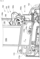
Fig. 3 is a side view according to the arrow III and in section through a vertical plane of the card feeder ofFig. 2 ; -
Fig. 4 is a side view according to the arrow IV of the card feeder ofFig. 2 ; -
Fig. 5 is a top view in section according to the plane V-V of the card feeder ofFig. 4 ; and -
Fig. 6 is a sectional view of the card feeder ofFig. 5 by the plan VI-VI. - In the following description, the terms relating to a position are considered with reference to a
processing machine 100 including acard feeder 150 according to the invention, where theprocessing machine 100 is in the position of use, i.e., as shown inFig. 1 . - The
processing machine 100 includes acard feeder 150 according to the invention, aprocessing module 102, and atransport system 104 which includes means for moving the cards from thecard feeder 150 to theprocessing module 102, where the means conventionally include rolls which pinch the cards and motors which drive the rolls in rotation. Thus, theprocessing module 102 is downstream of thecard feeder 150 with respect to the direction of movement D of the cards by thetransport system 104. For example, theprocessing module 102 is a printer or an encoding module, etc. Theprocessing module 102 and thetransport system 104 will not be described in more detail because they can take on any form known to a person skilled in the art. -
Figs. 2 to 6 show thecard feeder 150 from different angles. Thecard feeder 150 includes aframe 152 which is secured to the frame of theprocessing machine 100. Theframe 152 of thecard feeder 150 may be a portion of the frame of theprocessing machine 100 or an attached and fixed element. - The
card feeder 150 includes areservoir 156 which is herein delimited by threevertical walls 156a-c, namely aback wall 156c and twolateral walls 156a-b arranged on either side of theback wall 156c. Thesevertical walls 156a-c are secured to theframe 152 and thus form, when viewed from above, a U-like shape, where thelateral walls 156a-b form the branches of the U-like shape and where theback wall 156c forms the bottom of the U-like shape. - In the lower part, the
reservoir 156 has atray 154 which forms the base of thereservoir 156 and above which asupport 154a is provided which serves as a support for astack 52 of cards, such as plastic cards, 50 placed thereon. Thus, thestack 52 ofcards 50 is formed by a vertical stack ofcards 50 which are placed flat on top of one another and over thesupport 154a. Thus, thestack 52 ofcards 50 is arranged between thevertical walls 156a-c and over thesupport 154a. The installation of thesupport 154a with a reduced surface area relative to thetray 154 allows minimizing the frictions of thecards 50 when they move. - The
card feeder 150 also includes adoor 162 which is movably mounted on theframe 152 and which forms the fourth wall of thereservoir 156. Thus, thedoor 162 is movably mounted on theframe 152 between an open position, enabling access to the inside of thereservoir 156 and the deposition ofcards 50 on thesupport 154a, and a closed position, preventing access to thereservoir 156 while enclosing thecards 50 in thereservoir 156, and vice versa. Thus, thedoor 162 closes the U-like shape formed by thevertical walls 156a-c. - In the embodiment of the invention disclosed herein, the
door 162 is movable in rotation about adoor axis 162a, herein vertical. - In the lower portion of the
reservoir 156, thecard feeder 150 also includes aseparation system 158 which is arranged so as to separate thecards 50 stored in thereservoir 156 from each other, while moving them successively through thebottom wall 156c according to a drive direction F which is then extended by direction of movement D. - The
separation system 158 includes aseparation roll 158a which is arranged at the level of thetray 154 according to a direction transverse to the drive direction F. Theseparation roll 158a is mounted movable in rotation on theframe 152 about itsaxis 158b. Thus, thecards 50 are in contact with the top of theseparation roll 158a and the top of thesupport 154a. - The
separation system 158 also includes a drive system, such as a motor, mounted on theframe 152, which is arranged so as to drive theseparation roll 158a in rotation in the direction of the arrow R to drive thecard 50 following the drive direction F. Theprocessing machine 100 or thecard feeder 150 includes a control unit arranged so as to control the drive system according to the needs. - Thus, the
stack 52 ofcards 50 rests on theseparation roll 158a and thesupport 154a, and the separation is thus performed from below thestack 52, i.e., theseparation roll 158a drives thecard 50 which is the lowest, i.e., which rests on theseparation roll 158a and thesupport 154a, to pull it out of thestack 52 and move it following the drive direction F through thebottom wall 156c through awindow 164 that thebottom wall 156c has for this purpose. - Conventionally, the
window 164 is sized in height to let only onecard 50 pass through at a time. - The
separation roll 158a drives thecard 50 up to thetransport system 104 which handles it to transfer it to theprocessing module 102 and expel it from themachine 100 after processing. - To assist in the separation of the
cards 50 by theseparation roll 158a, thesupport 154a is arranged so that thelowest card 50 has an orientation with a descending slope towards theseparation roll 158a. - The
card feeder 150 also includes aballast 160 which is movably mounted on theframe 152 between a support position (continuous lines inFig. 3 ) and a stowed position (phantom lines inFig. 3 ). - In the support position, the
ballast 160 bears on the top of thestack 52, i.e., on thecard 50 which is the highest, and in the stowed position, theballast 160 is on one side ofstack 52, herein at the front of thestack 52, without pressing on thestack 52. The support position of theballast 160 varies according to the number ofremaining cards 50. - Thus, in the support position, the
ballast 160 is in thereservoir 156 and, in the stowed position, it is outside thereservoir 156. Between the support position and the stowed position, theballast 160 passes through thebottom wall 156c via apassage 166 that thebottom wall 156c has for this purpose above thewindow 164. - In the support position, the
ballast 160 presses thecards 50 against theseparation roll 158a to assist with the separation. - In the stowed position, the
ballast 160 does not bear on thecards 50 and it is the cumulative weight of thecards 50 of thestack 52 which acts to press thecards 50 against theseparation roll 158a. - According to a particular embodiment, the weight of the
ballast 160 is equivalent to the weight of 15 ±3 cards. - The
card feeder 150 also includes atransmission system 170 which is arranged so as to move theballast 160 from the support position into the stowed position when thedoor 162 passes from the closed position into the open position. Thus, when a user opens thedoor 162, theballast 160 passes into the stowed position to allow free access above thesupport 154a and theseparation roll 158a in order to enable removal of astack 52 ofcards 50. - When the deposited
stack 52 ofcards 50 is relatively high, i.e., above theballast 160, saidballast 160 remains stuck in the stowed position due to the fact that it bears against the side of the stack 52 (cf. the stowed position inFig. 3 ), herein the front of thestack 52, and this support prevents it from returning back to the support position. - As the
stack 52 decreases, thecard 50 that is the highest in thestack 52 goes down. When thiscard 50 passes below the level of theballast 160, saidballast 160 is then free to return back to its support position by bearing on saidhighest card 50 and following it as it descends. - Moreover, the
transmission system 170 is not intended to bring theballast 160 back to the support position, so as not to force theballast 160 against thestack 52 when thedoor 162 passes from the open position into the closed position. - To ensure the return of the
ballast 160 back to the support position, thecard feeder 150 includes areturn system 172 which is arranged so as to automatically return theballast 160 back to the support position when it is in the stowed position. Thisreturn system 172 is different from thetransmission system 170 so as not to link the return of theballast 160 to closure of thedoor 162. - With such an arrangement, the
ballast 160 assists in picking thecards 50 by theseparation system 158, without hindering the placement of thecards 50 in thereservoir 156 and without forcing theballast 160 against thestack 52. - In the embodiment of the invention shown in
Figs. 3 and6 , theballast 160 is mounted movable in rotation about a tiltingaxis 160a directed according to a transverse direction, i.e. parallel to theaxis 158b of theseparation roll 158a. - In this case, the
ballast 160 includes aweight 160b and twoarms 160c which are secured to theweight 160b and where each is mounted movable in rotation about the tiltingaxis 160a. - The tilting
axis 160a is arranged so that the center of gravity G of theballast 160, i.e., herein of theweight 160b and of thearms 160c, is vertically above the tiltingaxis 160a and horizontally between the tiltingaxis 160a and thereservoir 156, and therefore thestack 52, when theballast 160 is in the stowed position. - Thus, in this position, gravity tends to bring the
ballast 160 back into the support position when theballast 160 no longer bears against thestack 52. As the height of thestack 52 decreases, the pressure exerted by theballast 160 will increase. - Thus, in this embodiment, the
return system 172 is gravity which is exerted on theballast 160 at its center of gravity G. - In another embodiment, a spring may be arranged so as to return the
ballast 160 back to the support position when it is moved away. - In the embodiment of the invention described herein, the
transmission system 170 includes aslider 174 which is mounted movable in translation on theframe 152 parallel to a direction of translation T perpendicular to the tiltingaxis 160a, and herein generally horizontal. - In the embodiment of the invention described herein, the translational movement is achieved by fastening the
slider 174 on theframe 152 by twofastening screws 174a which are screwed into theframe 152 throughoblong holes 174b that pass through theslider 174, and where the major axis of eachoblong hole 174b is parallel to the direction of translation T. - Of course, it is possible to achieve this translational movement by other means, such as rails for example.
- Moreover, the
slider 174 is linked to theballast 160 via a slidingpivot connection 176. To this end, thetransmission system 170 includes ashaft 176a secured to theballast 160 and ahousing 176b which is formed in theslider 174. - The
shaft 176a is herein parallel to the tiltingaxis 160a but offset with respect to the latter. Thus, any movement of theshaft 176a will drive theballast 160 in rotation about the tiltingaxis 160a and vice versa. - The
housing 176b is sized so as to prevent any movement parallel to the direction of translation T between theslider 174 and theshaft 176a and to authorize movements perpendicular to the direction of translation T, herein vertical movements, between theslider 174 and theshaft 176a. - Thus, as soon as the
slider 174 moves according to the translation direction T, theshaft 176a is forced to move at the same time and, due to the rotation of theballast 160 about the tiltingaxis 160a, theshaft 176a moves perpendicular to the direction of translation T in thehousing 176b. - Conversely, as soon as the
shaft 176a moves in rotation under the effect of theballast 160, theslider 174 is forced to move at the same time according to the direction of translation T and theshaft 176a moves perpendicular to the direction of translation T in thehousing 176b. - Thus, the
slider 174 moves between a first position corresponding to the support position of theballast 160 when there is no longer anycard 50 in thereservoir 156 and a second position corresponding to the stowed position of theballast 160. - The
transmission system 170 also includes acam 162b secured to thedoor 162 and which therefore moves with it during movement thereof between the open and closed positions. - The
slider 174 includes astop 174c which forms a follower element for thecam 162b when the latter moves from the closed position into the open position. Thus, thecam 162b and thestop 174c are arranged so that thestop 174c follows thecam 162b during movement thereof from the closed position into the open position and theslider 174 then passes from the first position (support position of the ballast 160) into the second position (stowed position of the ballast 160), but thestop 174c and therefore theslider 174 are not forced to follow thecam 162b during movement of the latter from the open position into the closed position. - The
cam 162b is herein in the form of a circle arc coaxial with thedoor axis 162a, and thestop 174c is in the form of a wall of theslider 174c, where the wall is positioned so as to be pushed by thecam 162b during movement thereof from the closed position into the open position and so as to thus move theslider 174 from the first position into the second position. - The operation is then as follows from the closed position of the
door 162 and from the support position of theballast 160 and into the first position of theslider 174. - A user manipulates the
door 162 to place it in the open position. The cooperation between thecam 162b and thestop 174c forces theslider 174 to move into the second position, and the cooperation between thehousing 176b and theshaft 176a causes movement of theballast 160 into its stowed position. The user can then deposit thecards 50 in thereservoir 156. - The user manipulates the
door 162 to set it in the closed position. Thecam 162b does not act on thestop 174c which therefore remains in the same position due to the fact that theballast 160 is blocked by thestack 52. As the stack decreases, theballast 160 will pivot about the tiltingaxis 160a while moving from the stowed position into the support position and while driving theshaft 176a, and, due to the cooperation of theshaft 176a with thehousing 176b, theslider 174 will move towards its first position.
Claims (3)
- A card feeder (150) for a processing machine (100), the card feeder (150) comprising:- a frame (152);- a reservoir (156) at the base of which a tray (154) is arranged, and above the tray (154), a support (154a) intended to receive a stack (52) of cards (50);- a separation system (158) including a separation roll (158a) arranged at a level of the tray (154) and a drive system arranged so as to move the separation roll (158a) in rotation;- a ballast (160) movably mounted on the frame (152) between a support position in which the ballast (160) bears on a top of the stack (52) of cards (50) and a stowed position in which the ballast (160) is on one side of the stack (52) of cards (50);- a door (162) movably mounted on the frame (152) between an open position enabling access to the reservoir (158) and a closed position preventing access to the reservoir (158);- a transmission system (170) arranged so as to move the ballast (160) from the support position into the stowed position when the door (162) passes from the closed position into the open position; and- a return system (172) arranged so as to bring the ballast (160) back into the support position when it is in the stowed position, characterized in that the ballast (160) is mounted movable in rotation about a tilting axis (160a) parallel to an axis (158b) of the separation roll (158a), wherein the tilting axis (160a) is arranged so that a center of gravity (G) of the ballast (160) is vertically above the tilting axis (160a) and horizontally between the tilting axis (160a) and the reservoir (156) when the ballast (160) is in the stowed position, and wherein the return system (172) is gravity.
- The card feeder (150) according to claim 1, wherein the transmission system (170) comprises:- a cam (162b) secured to the door (162) and moveable therewith between the open position and the closed position;- a shaft (176) secured to the ballast (160) parallel to the tilting axis (160a) and offset with respect to the tilting axis; and- a slider (174) mounted movable in a direction of translation (T) on the frame (152) and including a stop (174c) forming a follower element for the cam (162b), wherein the slider (174) moves from a first position corresponding to the support position of the ballast (160) into a second position corresponding to the stowed position of the ballast (160) when the cam (162b) moves from the closed position into the open position, and the slider (174) having a housing (176b) in which the shaft (176a) is accommodated, wherein the housing (176b) is arranged so as to prevent any movement parallel to the direction of translation (T) between the slider (174) and the shaft (176a) and enable movement perpendicular to the direction of translation (T) between the slider (174) and the shaft (176a).
- A card processing machine (100) comprising a card feeder (150) according to one of the preceding claims, a processing module (102), and a transport system (104) including means for moving the cards (50) from the card feeder (150) to the processing module (102).
Applications Claiming Priority (2)
| Application Number | Priority Date | Filing Date | Title |
|---|---|---|---|
| FR2307375A FR3151030B1 (en) | 2023-07-10 | 2023-07-10 | CARD LOADER FOR A CARD PROCESSING MACHINE |
| US18/739,512 US20250019189A1 (en) | 2023-07-10 | 2024-06-11 | Card feeder for a card processing machine |
Publications (2)
| Publication Number | Publication Date |
|---|---|
| EP4491552A1 EP4491552A1 (en) | 2025-01-15 |
| EP4491552B1 true EP4491552B1 (en) | 2025-06-18 |
Family
ID=91737893
Family Applications (1)
| Application Number | Title | Priority Date | Filing Date |
|---|---|---|---|
| EP24186956.9A Active EP4491552B1 (en) | 2023-07-10 | 2024-07-05 | Card feeder for a card processing machine |
Country Status (1)
| Country | Link |
|---|---|
| EP (1) | EP4491552B1 (en) |
Family Cites Families (3)
| Publication number | Priority date | Publication date | Assignee | Title |
|---|---|---|---|---|
| US3948506A (en) * | 1975-02-18 | 1976-04-06 | Xerox Corporation | Tuned card weight |
| US7665920B2 (en) * | 2007-03-08 | 2010-02-23 | Fargo Electronics, Inc. | Card holder for a credential production device |
| IT201800010512A1 (en) * | 2018-11-23 | 2019-02-23 | Ixla S R L | Plastic card feeding device for card handling devices and card handling device comprising said feeding device |
-
2024
- 2024-07-05 EP EP24186956.9A patent/EP4491552B1/en active Active
Also Published As
| Publication number | Publication date |
|---|---|
| EP4491552A1 (en) | 2025-01-15 |
Similar Documents
| Publication | Publication Date | Title |
|---|---|---|
| AU575858B2 (en) | Card feeding, transfer and output apparatus for an automatic embossing system | |
| AU587805B2 (en) | In-mold label dispenser for plastic blow molding machine | |
| US4494743A (en) | Dispenser picker apparatus | |
| US4594838A (en) | Capping method and apparatus for a beverage vendor | |
| JP2770208B2 (en) | Method and apparatus for separating sheet-shaped recording media | |
| CN109625369B (en) | Square material divides lid and buckle closure machine | |
| WO1990005641A1 (en) | Sheet stacking and stapling device | |
| DE3231402C2 (en) | Machine for the automatic acceptance and dispensing of banknotes | |
| EP4491552A1 (en) | Card feeder for a card processing machine | |
| JPH0723140B2 (en) | Packaging equipment for cigarettes | |
| US20250019189A1 (en) | Card feeder for a card processing machine | |
| JPS6128567B2 (en) | ||
| GB2094397A (en) | Apparatus for dispensing sheets | |
| WO2026060866A1 (en) | Card recycling device | |
| US6536194B2 (en) | Method and apparatus for feeding DVD or CD boxes, empty and closed, to means for opening, customizing, filing and closing said boxes | |
| US6305526B1 (en) | Ampule transfer unit | |
| AU1855792A (en) | Multiple tray rotary paper feed system for an image reproduction machine | |
| US5456573A (en) | Stacker slide | |
| US4262817A (en) | Elevator mechanism for automatic teller machine | |
| CN117815646A (en) | Poker machine and poker card arrangement method thereof | |
| KR20080020467A (en) | Card feeder | |
| CN111153093B (en) | Teller all-in-one machine | |
| US4906163A (en) | Stacking machine for making a plurality of stacks of disk-like workpieces, especially can covers | |
| JPH0546136Y2 (en) | ||
| CN220105758U (en) | Self-locking drawing mechanism for ticket vending machine |
Legal Events
| Date | Code | Title | Description |
|---|---|---|---|
| PUAI | Public reference made under article 153(3) epc to a published international application that has entered the european phase |
Free format text: ORIGINAL CODE: 0009012 |
|
| STAA | Information on the status of an ep patent application or granted ep patent |
Free format text: STATUS: THE APPLICATION HAS BEEN PUBLISHED |
|
| AK | Designated contracting states |
Kind code of ref document: A1 Designated state(s): AL AT BE BG CH CY CZ DE DK EE ES FI FR GB GR HR HU IE IS IT LI LT LU LV MC ME MK MT NL NO PL PT RO RS SE SI SK SM TR |
|
| STAA | Information on the status of an ep patent application or granted ep patent |
Free format text: STATUS: REQUEST FOR EXAMINATION WAS MADE |
|
| 17P | Request for examination filed |
Effective date: 20250128 |
|
| GRAP | Despatch of communication of intention to grant a patent |
Free format text: ORIGINAL CODE: EPIDOSNIGR1 |
|
| STAA | Information on the status of an ep patent application or granted ep patent |
Free format text: STATUS: GRANT OF PATENT IS INTENDED |
|
| RIC1 | Information provided on ipc code assigned before grant |
Ipc: B65H 3/54 20060101ALI20250221BHEP Ipc: B65H 3/06 20060101ALI20250221BHEP Ipc: B65H 1/10 20060101ALI20250221BHEP Ipc: B65H 1/06 20060101AFI20250221BHEP |
|
| INTG | Intention to grant announced |
Effective date: 20250311 |
|
| GRAS | Grant fee paid |
Free format text: ORIGINAL CODE: EPIDOSNIGR3 |
|
| GRAA | (expected) grant |
Free format text: ORIGINAL CODE: 0009210 |
|
| STAA | Information on the status of an ep patent application or granted ep patent |
Free format text: STATUS: THE PATENT HAS BEEN GRANTED |
|
| AK | Designated contracting states |
Kind code of ref document: B1 Designated state(s): AL AT BE BG CH CY CZ DE DK EE ES FI FR GB GR HR HU IE IS IT LI LT LU LV MC ME MK MT NL NO PL PT RO RS SE SI SK SM TR |
|
| REG | Reference to a national code |
Ref country code: GB Ref legal event code: FG4D |
|
| REG | Reference to a national code |
Ref country code: CH Ref legal event code: EP |
|
| REG | Reference to a national code |
Ref country code: DE Ref legal event code: R096 Ref document number: 602024000213 Country of ref document: DE |
|
| REG | Reference to a national code |
Ref country code: CH Ref legal event code: EP |
|
| REG | Reference to a national code |
Ref country code: IE Ref legal event code: FG4D |
|
| RAP4 | Party data changed (patent owner data changed or rights of a patent transferred) |
Owner name: EVOLIS SAS |
|
| REG | Reference to a national code |
Ref country code: DE Ref legal event code: R081 Ref document number: 602024000213 Country of ref document: DE Owner name: EVOLIS SAS, FR Free format text: FORMER OWNER: EVOLIS SA, BEAUCOUZE, FR |
|
| PG25 | Lapsed in a contracting state [announced via postgrant information from national office to epo] |
Ref country code: FI Free format text: LAPSE BECAUSE OF FAILURE TO SUBMIT A TRANSLATION OF THE DESCRIPTION OR TO PAY THE FEE WITHIN THE PRESCRIBED TIME-LIMIT Effective date: 20250618 |
|
| REG | Reference to a national code |
Ref country code: LT Ref legal event code: MG9D |
|
| PG25 | Lapsed in a contracting state [announced via postgrant information from national office to epo] |
Ref country code: NO Free format text: LAPSE BECAUSE OF FAILURE TO SUBMIT A TRANSLATION OF THE DESCRIPTION OR TO PAY THE FEE WITHIN THE PRESCRIBED TIME-LIMIT Effective date: 20250918 Ref country code: GR Free format text: LAPSE BECAUSE OF FAILURE TO SUBMIT A TRANSLATION OF THE DESCRIPTION OR TO PAY THE FEE WITHIN THE PRESCRIBED TIME-LIMIT Effective date: 20250919 |
|
| PG25 | Lapsed in a contracting state [announced via postgrant information from national office to epo] |
Ref country code: BG Free format text: LAPSE BECAUSE OF FAILURE TO SUBMIT A TRANSLATION OF THE DESCRIPTION OR TO PAY THE FEE WITHIN THE PRESCRIBED TIME-LIMIT Effective date: 20250618 |
|
| PG25 | Lapsed in a contracting state [announced via postgrant information from national office to epo] |
Ref country code: HR Free format text: LAPSE BECAUSE OF FAILURE TO SUBMIT A TRANSLATION OF THE DESCRIPTION OR TO PAY THE FEE WITHIN THE PRESCRIBED TIME-LIMIT Effective date: 20250618 |
|
| PGFP | Annual fee paid to national office [announced via postgrant information from national office to epo] |
Ref country code: FR Payment date: 20250703 Year of fee payment: 2 |
|
| PG25 | Lapsed in a contracting state [announced via postgrant information from national office to epo] |
Ref country code: RS Free format text: LAPSE BECAUSE OF FAILURE TO SUBMIT A TRANSLATION OF THE DESCRIPTION OR TO PAY THE FEE WITHIN THE PRESCRIBED TIME-LIMIT Effective date: 20250918 |
|
| REG | Reference to a national code |
Ref country code: NL Ref legal event code: MP Effective date: 20250618 |
|
| PG25 | Lapsed in a contracting state [announced via postgrant information from national office to epo] |
Ref country code: LV Free format text: LAPSE BECAUSE OF FAILURE TO SUBMIT A TRANSLATION OF THE DESCRIPTION OR TO PAY THE FEE WITHIN THE PRESCRIBED TIME-LIMIT Effective date: 20250618 |
|
| PG25 | Lapsed in a contracting state [announced via postgrant information from national office to epo] |
Ref country code: NL Free format text: LAPSE BECAUSE OF FAILURE TO SUBMIT A TRANSLATION OF THE DESCRIPTION OR TO PAY THE FEE WITHIN THE PRESCRIBED TIME-LIMIT Effective date: 20250618 |
|
| PG25 | Lapsed in a contracting state [announced via postgrant information from national office to epo] |
Ref country code: PT Free format text: LAPSE BECAUSE OF FAILURE TO SUBMIT A TRANSLATION OF THE DESCRIPTION OR TO PAY THE FEE WITHIN THE PRESCRIBED TIME-LIMIT Effective date: 20251020 |
|
| REG | Reference to a national code |
Ref country code: AT Ref legal event code: MK05 Ref document number: 1804030 Country of ref document: AT Kind code of ref document: T Effective date: 20250618 |
|
| PG25 | Lapsed in a contracting state [announced via postgrant information from national office to epo] |
Ref country code: IS Free format text: LAPSE BECAUSE OF FAILURE TO SUBMIT A TRANSLATION OF THE DESCRIPTION OR TO PAY THE FEE WITHIN THE PRESCRIBED TIME-LIMIT Effective date: 20251018 |
|
| PG25 | Lapsed in a contracting state [announced via postgrant information from national office to epo] |
Ref country code: AT Free format text: LAPSE BECAUSE OF FAILURE TO SUBMIT A TRANSLATION OF THE DESCRIPTION OR TO PAY THE FEE WITHIN THE PRESCRIBED TIME-LIMIT Effective date: 20250618 Ref country code: SM Free format text: LAPSE BECAUSE OF FAILURE TO SUBMIT A TRANSLATION OF THE DESCRIPTION OR TO PAY THE FEE WITHIN THE PRESCRIBED TIME-LIMIT Effective date: 20250618 |
|
| PG25 | Lapsed in a contracting state [announced via postgrant information from national office to epo] |
Ref country code: CZ Free format text: LAPSE BECAUSE OF FAILURE TO SUBMIT A TRANSLATION OF THE DESCRIPTION OR TO PAY THE FEE WITHIN THE PRESCRIBED TIME-LIMIT Effective date: 20250618 |
|
| PG25 | Lapsed in a contracting state [announced via postgrant information from national office to epo] |
Ref country code: PL Free format text: LAPSE BECAUSE OF FAILURE TO SUBMIT A TRANSLATION OF THE DESCRIPTION OR TO PAY THE FEE WITHIN THE PRESCRIBED TIME-LIMIT Effective date: 20250618 |
|
| PG25 | Lapsed in a contracting state [announced via postgrant information from national office to epo] |
Ref country code: EE Free format text: LAPSE BECAUSE OF FAILURE TO SUBMIT A TRANSLATION OF THE DESCRIPTION OR TO PAY THE FEE WITHIN THE PRESCRIBED TIME-LIMIT Effective date: 20250618 |
|
| PG25 | Lapsed in a contracting state [announced via postgrant information from national office to epo] |
Ref country code: SK Free format text: LAPSE BECAUSE OF FAILURE TO SUBMIT A TRANSLATION OF THE DESCRIPTION OR TO PAY THE FEE WITHIN THE PRESCRIBED TIME-LIMIT Effective date: 20250618 |
|
| PG25 | Lapsed in a contracting state [announced via postgrant information from national office to epo] |
Ref country code: ES Free format text: LAPSE BECAUSE OF FAILURE TO SUBMIT A TRANSLATION OF THE DESCRIPTION OR TO PAY THE FEE WITHIN THE PRESCRIBED TIME-LIMIT Effective date: 20250618 |
|
| REG | Reference to a national code |
Ref country code: DE Ref legal event code: R097 Ref document number: 602024000213 Country of ref document: DE |
|
| PG25 | Lapsed in a contracting state [announced via postgrant information from national office to epo] |
Ref country code: MC Free format text: LAPSE BECAUSE OF FAILURE TO SUBMIT A TRANSLATION OF THE DESCRIPTION OR TO PAY THE FEE WITHIN THE PRESCRIBED TIME-LIMIT Effective date: 20250618 |
|
| PG25 | Lapsed in a contracting state [announced via postgrant information from national office to epo] |
Ref country code: DK Free format text: LAPSE BECAUSE OF FAILURE TO SUBMIT A TRANSLATION OF THE DESCRIPTION OR TO PAY THE FEE WITHIN THE PRESCRIBED TIME-LIMIT Effective date: 20250618 |
|
| PLBE | No opposition filed within time limit |
Free format text: ORIGINAL CODE: 0009261 |
|
| STAA | Information on the status of an ep patent application or granted ep patent |
Free format text: STATUS: NO OPPOSITION FILED WITHIN TIME LIMIT |
|
| REG | Reference to a national code |
Ref country code: CH Ref legal event code: L10 Free format text: ST27 STATUS EVENT CODE: U-0-0-L10-L00 (AS PROVIDED BY THE NATIONAL OFFICE) Effective date: 20260430 |